Design of Solar Input EZ-Source Inverter . · PDF fileDesign of Solar Input EZ-Source...
6
International Research Journal of Engineering and Technology (IRJET) e-ISSN: 2395-0056 Volume: 02 Issue: 06 | Sep-2015 www.irjet.net p-ISSN: 2395-0072 © 2015, IRJET ISO 9001:2008 Certified Journal Page 583 Abstract: Z-Source inverters are used mainly for buck- boost energy conversion with the help of passive elements. In Z-source inverter topology, LC impedance network is used to couples the source and the inverter to achieve voltage boost and inversion. Embedded EZ- Source inverter and Z-Source inverter can produce the same gain. Input to the Embedded EZ-Source inverter can be obtained from solar cell. The ripple content in the output voltage of solar cell is filtered and pure DC is given to the three-phase inverter which converts DC in to three-phase balanced AC. The output of the Embedded EZ Source inverter is used to control the harmonics present in the load. The limitations of the conventional Z-source inverter can be overcome by using Embedded Z-source inverters. It can produce smoother current and increase voltage level across the Z-source and it has low harmonic distortions (THD). Simulations are carried out using MATLAB-SIMULINK. Hardware implementation and Microcontroller programming can be done in the lab. Keywords: EZ-source inverters, voltage boost, Z- Source inverter and Pulse Width Modulation (PWM), Total Harmonic Distortion (THD). INTRODUCTION: The circuit which is used to convert the direct current (DC) input signals into alternating current (AC) output signal is called as inverter. Traditionally there exist two types of inverters namely Voltage Source Inverter, Current Source Inverter [10]. Voltage source inverter is a buck (step-down) inverter for dc-to-ac power conversion and the voltage source converter is a boost (step-up) rectifier for ac-to-dc power conversion [6] [10]. Current source inverter is a boost inverter for dc-to-ac power conversion and a buck rectifier (or buck converter) for ac-to-dc power conversion [6] [10]. Both the V-source converter and the I- source converter have the common problem that they can operate either a boost or buck converters and cannot be a buck–boost converter. The limitations of the traditional voltage source and current source converters can be eliminated by introducing Z-source inverter [6]. Z-Source inverter utilize LC impedance network which performs both buck-boost energy conversions [1] [2] [4]. It can be used in implementing dc-to-ac, ac-to-dc, ac-to-ac, and dc-to-dc power conversion. The Z-source network boosts the input voltage level for inverter and also provides filtered output. Thus this technique improves efficiency of inverter. The structure Z-source consist two inductors and two capacitors arranged in X shape for buck boost operation in single stage conversion. To avoid chopping in source current an additional LC filter is placed before diode therefore the cost of system would rise and due to addition of LC filter the system becomes more complex. In the case of EZ source inverter, source is places in series with inductors which smoothens the source current and Simulation and Design of Solar Input EZ-Source Inverter System. 1 Vinay Y. Somwanshi, 2 Syed A. Naveed 1 Student, Department of Electronics and Telecommunication, MGM’s JNEC Aurangabad, Maharashtra, India 2 Professor, Department of Electronics and Telecommunication, MGM’s JNEC Aurangabad, Maharashtra, India 1 [email protected], 2 [email protected].
Transcript of Design of Solar Input EZ-Source Inverter . · PDF fileDesign of Solar Input EZ-Source...
International Research Journal of Engineering and Technology (IRJET) e-ISSN: 2395-0056
Volume: 02 Issue: 06 | Sep-2015 www.irjet.net p-ISSN: 2395-0072
© 2015, IRJET ISO 9001:2008 Certified Journal Page 583
Abstract: Z-Source inverters are used mainly for buck-
boost energy conversion with the help of passive
elements. In Z-source inverter topology, LC impedance
network is used to couples the source and the inverter
to achieve voltage boost and inversion. Embedded EZ-
Source inverter and Z-Source inverter can produce the
same gain. Input to the Embedded EZ-Source inverter
can be obtained from solar cell. The ripple content in
the output voltage of solar cell is filtered and pure DC is
given to the three-phase inverter which converts DC in
to three-phase balanced AC. The output of the
Embedded EZ Source inverter is used to control the
harmonics present in the load.
The limitations of the conventional Z-source
inverter can be overcome by using Embedded Z-source
inverters. It can produce smoother current and increase
voltage level across the Z-source and it has low
harmonic distortions (THD). Simulations are carried
out using MATLAB-SIMULINK. Hardware
implementation and Microcontroller programming can
be done in the lab.
Keywords: EZ-source inverters, voltage boost, Z-
Source inverter and Pulse Width Modulation (PWM),
Total Harmonic Distortion (THD).
INTRODUCTION:
The circuit which is used to convert the direct
current (DC) input signals into alternating current (AC)
output signal is called as inverter.
Traditionally there exist two types of inverters
namely Voltage Source Inverter, Current Source Inverter
[10]. Voltage source inverter is a buck (step-down)
inverter for dc-to-ac power conversion and the voltage
source converter is a boost (step-up) rectifier for ac-to-dc
power conversion [6] [10]. Current source inverter is a
boost inverter for dc-to-ac power conversion and
Traditionally there exist two types of inverters namely
Voltage Source Inverter, Current Source Inverter [10].
Voltage source inverter is a buck (step-down) inverter for
dc-to-ac power conversion and the voltage source
converter is a boost (step-up) rectifier for ac-to-dc power
conversion [6] [10]. Current source inverter is a boost
inverter for dc-to-ac power conversion and
a buck rectifier (or buck converter) for ac-to-dc power
conversion [6] [10]. Both the V-source converter and the I-
source converter have the common problem that they can
operate either a boost or buck converters and cannot be a
buck–boost converter.
The limitations of the traditional voltage source
and current source converters can be eliminated by
introducing Z-source inverter [6]. Z-Source inverter utilize
LC impedance network which performs both buck-boost
energy conversions [1] [2] [4]. It can be used in
implementing dc-to-ac, ac-to-dc, ac-to-ac, and dc-to-dc
power conversion. The Z-source network boosts the input
voltage level for inverter and also provides filtered output. Thus this technique improves efficiency of inverter.
The structure Z-source consist two inductors and
two capacitors arranged in X shape for buck boost
operation in single stage conversion. To avoid chopping in
source current an additional LC filter is placed before
diode therefore the cost of system would rise and due to
addition of LC filter the system becomes more complex. In
the case of EZ source inverter, source is places in series
with inductors which smoothens the source current and
Simulation and Design of Solar Input EZ-Source Inverter System.
1Vinay Y. Somwanshi, 2Syed A. Naveed
1Student, Department of Electronics and Telecommunication, MGM’s JNEC Aurangabad, Maharashtra, India 2Professor, Department of Electronics and Telecommunication, MGM’s JNEC Aurangabad, Maharashtra, India
International Research Journal of Engineering and Technology (IRJET) e-ISSN: 2395-0056
Volume: 02 Issue: 06 | Sep-2015 www.irjet.net p-ISSN: 2395-0072
© 2015, IRJET ISO 9001:2008 Certified Journal Page 584
chopping currents get filtered without any additional LC
filter [1] [3].
For system design of EZ-Source inverter two PV
panels are required. These PV panels work as a dc source
which embedded within LC impedance network. The two
DC source generate varying DC voltages whose values are
depend on atmospheric conditions Voltage and current
filtering can be done by using LC components.
1. Z-SOURCE INVERTER
Fig.1. shows the circuit of Z-source inverter where the
input dc source and three-phase inverter bridge is
connected by X-shape network which is LC impedance
network. Any two switches from the same phase-leg of
inverter can be turned on safely to introduce a shoot-
through state which is nothing but the short-circuit state.
This condition can be brought by addition of LC impedance
network. The inductive element (L1, L2, or both) used to
limit the current paths from dc front-end. Due to insertion
of shoot-through state, the Z-source inverter can provides
voltage-boosting capability. Consider the inverter-state
equations during shoot-through and non shoot-through
states, expressed by (1) and (4) with a balanced network
assumed (L1 = L2 = L and C1 = C2 = C). These equations are
used to derive the gain of inverter.
Fig-1: Z-source inverter
Conditions of Shoot-Through state: (Sx = Sx1 = ON, x = A, B, or C; D = OFF) vL =VC; vi = 0; vd = 2VC; vD = Vdc − 2VC---- (1)
iL = − Ic; ii = iL − iC; idc = 0---- (2) Conditions of Non Shoot-Through state: (Sx ≠Sx1, x = A, B, or C; D = ON) vL =Vdc − VC ;vi = 2VC – Vdc; vd = Vdc; vD = 0 ---(3) idc =iL + iC; ii = iL – iC; idc ≠ 0--- (4) The following expressions are for VC capacitive voltage,
peak dc-link voltage ˆvi, and peak ac output voltage vx.
VC =(1 − T0/T)/(1 − 2T0/T ) *Vdc-----(5)
ˆvi = Vdc / (1 − 2T0/T)= BVdc------(6)
vx =M vi/2= B(M Vdc/2)------(7)
where T0/T denotes the shoot-through ratio (T0/T < 0.5)
per switching period, M is the modulation index used for
traditional inverter control, and B is boost factor given by
expression B = 1/(1 − 2T0/T ).
2. EMBEDDED Z-SOURCE INVERTER
Fig.2. shows the circuit of Embedded EZ-Source
inverter. It consist L1 and L2 inductive elements and C1
and C2 capacitive elements which forms LC impedance
network.
Fig-2: EZ-source inverter
Two DC sources embedded within the X-shaped LC
impedance network. In the case of voltage type EZ-source
inverter inductive elements L1 and L2 used for filtering
the currents and in case of current type EZ-source
inverters capacitive elements C1 and C2 used for voltage
filtering in current type EZ-source inverters keeping the
voltage or current gain of the inverter constant. The input

International Research Journal of Engineering and Technology (IRJET) e-ISSN: 2395-0056
Volume: 02 Issue: 06 | Sep-2015 www.irjet.net p-ISSN: 2395-0072
© 2015, IRJET ISO 9001:2008 Certified Journal Page 585
DC can be taken from the solar cell given to the Z-source.
The filtered, ripple free, pure DC given to the three phase
inverter which converts pure DC into three phase balanced
AC.
3. EXPERIMENTAL RESULTS
The simulation of proposed system is done in
MATLAB SIMULINK. The output voltage from two DC
sources fed to the Z filter of Embedded EZ-Source Inverter.
The filtered DC output from Z filter is given to the
Embedded EZ-Source Inverter which converts pure DC
into three phase balanced AC.
The simulation circuit diagram of Embedded EZ-
Source inverter is shown in fig.3. The triggering pulses for
switches of Embedded EZ-Source inverter is shown in fig.4.
The line current waveform is shown in fig.5, fig.6 and fig.7
represents line voltage waveforms.
The output from the Embedded EZ-Source Inverter is
given to the induction motor which is asynchronous
machine. Three phase induction motor is taken as a load.
Fig.8 shows the plot of rotor speed of induction motor with
respect to time. It represents the speed of induction motor
increases and settles down above 1600 RPM (Revolution
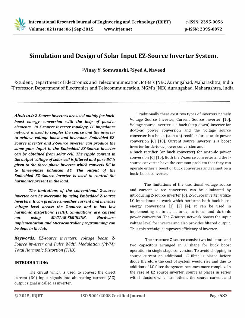
per minute). For calculation of total harmonic distortion
FFT analysis for current of the system is taken. It shows
that THD value is 3.93% shows in fig.9. Thus total
harmonic distortion is low in Embedded EZ-Source
inverter system.
Fig-3: Simulation circuit diagram
Fig-4: Triggering pulses

International Research Journal of Engineering and Technology (IRJET) e-ISSN: 2395-0056
Volume: 02 Issue: 06 | Sep-2015 www.irjet.net p-ISSN: 2395-0072
© 2015, IRJET ISO 9001:2008 Certified Journal Page 586
Fig-5: Line current waveform
Fig-6: Line voltage waveform
Fig-7: Phase to Phase voltage waveform
Fig-8: Rotor speed
International Research Journal of Engineering and Technology (IRJET) e-ISSN: 2395-0056
Volume: 02 Issue: 06 | Sep-2015 www.irjet.net p-ISSN: 2395-0072
© 2015, IRJET ISO 9001:2008 Certified Journal Page 587
Fig-9: FFT analysis and total harmonic distortion (THD)
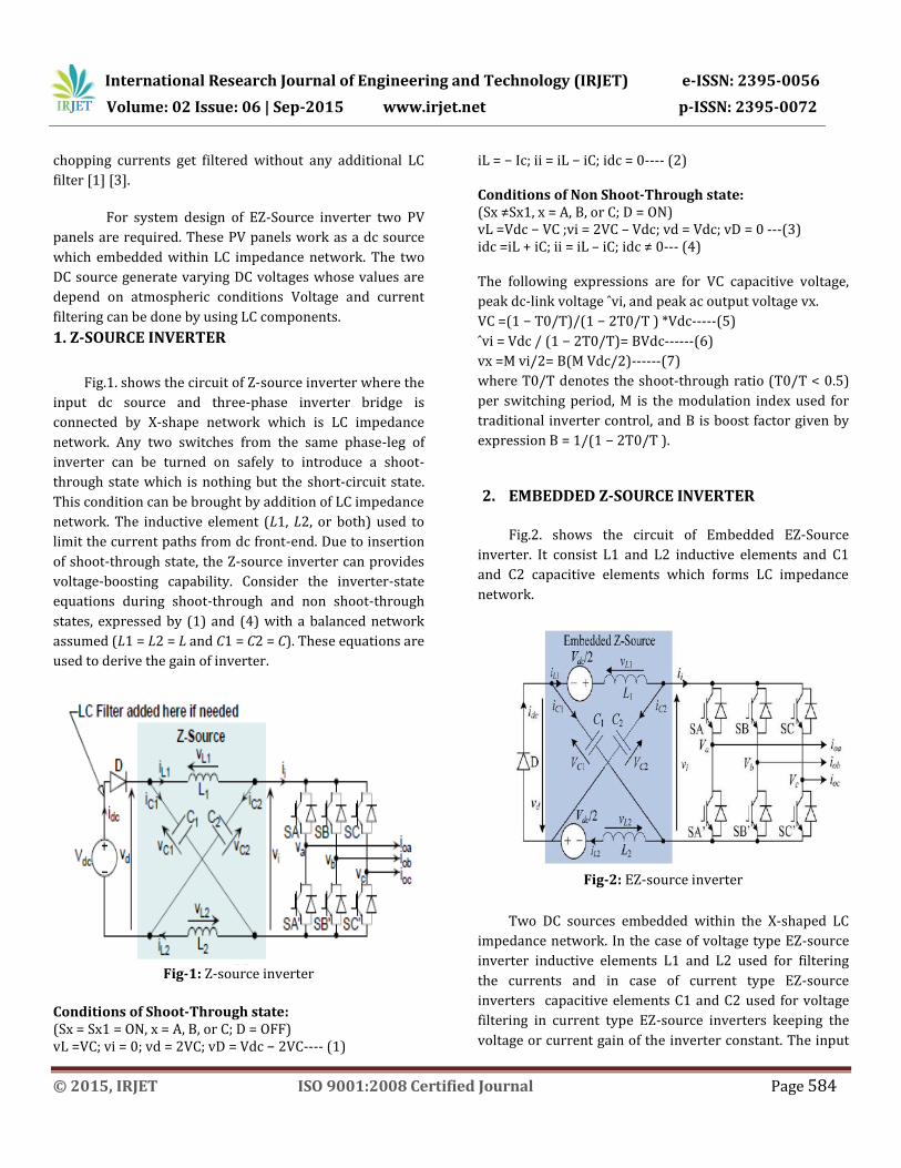
4. HARDWARE SETUP OF EZ-SOURCE INVERTER
Fig.10 shows the complete hardware setup of EZ-
source inverter. It consist power supply unit, Z-source
impedance network, induction motor as a load, driver
circuit for inverter and 6 switches three phase
inverter. Projections for solar input are provided in
the system. DC Input for the Z-source is provided by
the solar plates, filtered DC from Z-source fed to three
phase inverter. PIC microcontroller is used to provide
triggering pulses for three phase inverter through
driver circuit. Driver circuit amplifies the low level
voltage input pulses from PIC microcontroller into
high voltage level pulses. Three phase inverter
generates balanced AC signal to run induction motor.
Fig-10: Proposed system hardware
5. CONCLUSION
The simulation of EZ-Source inverter system is
carried out in MATLAB SIMULINK software. From the
experimental results are presented in this paper, we
observed that the given system provides voltage boosting
and current filtering using impedance network also it has
advantages of reduced harmonic distortions of about
3.93%. Its hardware implementation has been done and
results are obtained by using PV panels at input and motor
load at the output. Thus EZ-source inverter has great
advantages over current source and voltage source
inverters.
6. ACKNOWLEDGMENT
I wish to thank my project guide Dr. S. A. Naveed for
providing me a great technical support with his
knowledge and experience also I would like to express my
gratitude to my colleagues for their kind co-operation and
encouragement which help me in completion of this
project.

International Research Journal of Engineering and Technology (IRJET) e-ISSN: 2395-0056
Volume: 02 Issue: 06 | Sep-2015 www.irjet.net p-ISSN: 2395-0072
© 2015, IRJET ISO 9001:2008 Certified Journal Page 588
7. REFERENCES
[1] S. Kamalakkannan, S. Deve gowda, “Digital simulation
of renewable energy source controlled ez-source Inverter
system”, 2012 IEEE.
[2] P.Kannan, “Harmonic Analysis and Design of Embedded
Z-Source Inverter for Induction Motor Drives”, Volume-4
Number-1 Issue-14 March-2014.
[3] K.Spandana, G.N.Sreenivas, “Performance analysis of
partially parallel Embedded z (ez) - source inverter with
reduced switches fed im drives”, volume- 1, issue-3, jan.-
2014.
[4] Blaabjerg, Frede; Loh, Poh Chiang; Gao, F., “Embedded
EZ-Source Inverters”, (pp. 1-8). IEEE.
10.1109/08IAS.2008.300.
[5]N.Gurusakthi, R.Sivaprasad, “Performance
Enhancement of EZ-Source Inverter Using Induction
Motor”, Volume 4, Issue 4, April-2013.
[6] Fang Zheng Peng, “Z-Source Inverter”, vol. 39, no. 2,
march/april 2003.
[7] S. Rajakaruna, Member, IEEE and Y. R. L. Jayawickrama
“Designing Impedance Network of Z-Source Inverters”
[8]https://en.wikipedia.org/wiki/Z-source_inverter.
[9] “3-Phase Voltage Source Inverter with Square Wave
Output”.pdf, Version 2 EE IIT, Kharagpur
[10]Aaron VanderMeulen and John Maurin “Current
source inverter vs. Voltage source inverter topology”pdf.
8. AUTHORS BIOGRAPHIES
Vinay Y. Somwanshi
He is an Electronics and
Telecommunication Engineer. He
received his B.E. degree in
Electronics and
Telecommunication engineering
from Shreeyash college of
Engineering and Technology, BAMU, Aurangabad,
Maharashtra in 2013 and currently pursuing M.E.
(Electronics Engineering) from MGM’s JNEC College,
BAMU, Aurangabad, Maharashtra, India.
E-mail: [email protected]
Syed A. Naveed
His areas of interest are
power system, power quality,
power electronics and renewable
He is Professor in J. N.
Engineering College, Aurangabad
(M.S.), India. He has completed
B.E. (EEP), M.E. (EPS), Ph.D. (EEE) and LL.B. (Law) in 2000,
2001, 2009 and 2015 respectively. He has more than 12
years of experience in technical field at various levels in
academics. He has 34 national/ international technical
publications. He is Fellow Chartered Educator from
University Euro American Consortium, Madrid, Spain,
2013. He is Chartered Engineer with IE and Chartered
Industrial Environmentalist with SES. He has been
presented "Rajiv Gandhi Excellence Award" on 24-08-2013
and conferred with "The Best Citizens of India Award" in
2013. He is life member of various 77
national/international professional bodies related to
technical, industry, management, legal, environment,
medicine and social fields, energy sources.
E-mail: [email protected]