Design of Self-supporting Surfaces - Institute of … · The surface shown here, surprisingly, ......
11
Design of Self-supporting Surfaces Etienne Vouga Columbia Univ. / KAUST Mathias H ¨ obinger Evolute / TU Wien Johannes Wallner TU Graz / TU Wien Helmut Pottmann KAUST Figure 1: Left: Surfaces with irregularly placed holes are hard to realize as masonry, where the mortar between bricks must not be subject to tensile stresses. The surface shown here, surprisingly, has this property – it has been found as the nearest self-supporting shape from a given freeform geometry. The fictitious thrust network used in our algorithms is superimposed, with edges’ cross-section and coloring visualizing the magnitude of forces (warmer colors represent higher stresses.) Right: Curvature analysis with respect to the Airy stress surface tells us how to remesh shapes by self-supporting quad meshes with planar faces. This guides steel/glass constructions with low moments in nodes. Abstract Self-supporting masonry is one of the most ancient and elegant techniques for building curved shapes. Because of the very geomet- ric nature of their failure, analyzing and modeling such strutures is more a geometry processing problem than one of classical contin- uum mechanics. This paper uses the thrust network method of anal- ysis and presents an iterative nonlinear optimization algorithm for efficiently approximating freeform shapes by self-supporting ones. The rich geometry of thrust networks leads us to close connections between diverse topics in discrete differential geometry, such as a finite-element discretization of the Airy stress potential, perfect graph Laplacians, and computing admissible loads via curvatures of polyhedral surfaces. This geometric viewpoint allows us, in par- ticular, to remesh self-supporting shapes by self-supporting quad meshes with planar faces, and leads to another application of the theory: steel/glass constructions with low moments in nodes. CR Categories: I.3.5 [Computer Graphics]: Computational Ge- ometry and Object Modeling—Curve, surface, solid, and object representations; Keywords: Discrete differential geometry, architectural geome- try, self-supporting masonry, thrust networks, reciprocal force dia- grams, discrete Laplacians, isotropic geometry, mean curvature Links: DL PDF 1 Introduction Vaulted masonry structures are among the simplest and at the same time most elegant solutions for creating curved shapes in building construction. For this reason they have been an object of inter- est since antiquity; large, non-convex examples of such structures include gothic cathedrals. They continue to be an active topic of research today. Our paper is concerned with a combined geometry+statics analysis of self-supporting masonry and with tools for the interactive mod- eling of freeform self-supporting structures. Here “self-supporting” means that the structure, considered as an arrangement of blocks (bricks, stones), holds together by itself, with additional support present only during construction. This analysis is based on the fol- lowing assumptions, which follow the classic [Heyman 1966]: Assumption 1: Masonry has no tensile strength, but the individual building blocks do not slip against each other (because of friction or mortar). On the other hand, their compressive strength is suffi- ciently high so that failure of the structure is by a sudden change in geometry and not by material failure. Assumption 2 (The Safe Theorem): If a system of forces can be found which is in equilibrium with the load on the structure and which is contained within the masonry envelope then the structure will carry the loads, although the actual forces present may not be those postulated by that system. Our approach is twofold: We first give an overview of the con- tinuous case of a smooth surface under stress, which turns out to be governed locally by the Airy stress function. This mathemat- ical model is called a membrane in the engineering literature and has been applied to the analysis of masonry before. The surface is self-supporting if and only if stresses are entirely compressive. For computational purposes, stresses are discretized as a fictitious thrust network [Block and Ochsendorf 2007] contained in the ma- sonry structure; this network is a system of forces in equilibrium with the structure’s deadload. It can be interpreted as a finite ele- ment discretization of the continuous case, and it turns out to have very interesting geometry, with the Airy stress function becoming a
Transcript of Design of Self-supporting Surfaces - Institute of … · The surface shown here, surprisingly, ......
Design of Self-supporting Surfaces
Etienne VougaColumbia Univ. / KAUST
Mathias HobingerEvolute / TU Wien
Johannes WallnerTU Graz / TU Wien
Helmut PottmannKAUST
Figure 1: Left: Surfaces with irregularly placed holes are hard to realize as masonry, where the mortar between bricks must not be subject totensile stresses. The surface shown here, surprisingly, has this property – it has been found as the nearest self-supporting shape from a givenfreeform geometry. The fictitious thrust network used in our algorithms is superimposed, with edges’ cross-section and coloring visualizingthe magnitude of forces (warmer colors represent higher stresses.) Right: Curvature analysis with respect to the Airy stress surface tells ushow to remesh shapes by self-supporting quad meshes with planar faces. This guides steel/glass constructions with low moments in nodes.
Abstract
Self-supporting masonry is one of the most ancient and eleganttechniques for building curved shapes. Because of the very geomet-ric nature of their failure, analyzing and modeling such strutures ismore a geometry processing problem than one of classical contin-uum mechanics. This paper uses the thrust network method of anal-ysis and presents an iterative nonlinear optimization algorithm forefficiently approximating freeform shapes by self-supporting ones.The rich geometry of thrust networks leads us to close connectionsbetween diverse topics in discrete differential geometry, such asa finite-element discretization of the Airy stress potential, perfectgraph Laplacians, and computing admissible loads via curvaturesof polyhedral surfaces. This geometric viewpoint allows us, in par-ticular, to remesh self-supporting shapes by self-supporting quadmeshes with planar faces, and leads to another application of thetheory: steel/glass constructions with low moments in nodes.
CR Categories: I.3.5 [Computer Graphics]: Computational Ge-ometry and Object Modeling—Curve, surface, solid, and objectrepresentations;
Keywords: Discrete differential geometry, architectural geome-try, self-supporting masonry, thrust networks, reciprocal force dia-grams, discrete Laplacians, isotropic geometry, mean curvature
Links: DL PDF
1 Introduction
Vaulted masonry structures are among the simplest and at the sametime most elegant solutions for creating curved shapes in buildingconstruction. For this reason they have been an object of inter-est since antiquity; large, non-convex examples of such structuresinclude gothic cathedrals. They continue to be an active topic ofresearch today.
Our paper is concerned with a combined geometry+statics analysisof self-supporting masonry and with tools for the interactive mod-eling of freeform self-supporting structures. Here “self-supporting”means that the structure, considered as an arrangement of blocks(bricks, stones), holds together by itself, with additional supportpresent only during construction. This analysis is based on the fol-lowing assumptions, which follow the classic [Heyman 1966]:
Assumption 1: Masonry has no tensile strength, but the individualbuilding blocks do not slip against each other (because of frictionor mortar). On the other hand, their compressive strength is suffi-ciently high so that failure of the structure is by a sudden change ingeometry and not by material failure.
Assumption 2 (The Safe Theorem): If a system of forces can befound which is in equilibrium with the load on the structure andwhich is contained within the masonry envelope then the structurewill carry the loads, although the actual forces present may not bethose postulated by that system.
Our approach is twofold: We first give an overview of the con-tinuous case of a smooth surface under stress, which turns out tobe governed locally by the Airy stress function. This mathemat-ical model is called a membrane in the engineering literature andhas been applied to the analysis of masonry before. The surfaceis self-supporting if and only if stresses are entirely compressive.For computational purposes, stresses are discretized as a fictitiousthrust network [Block and Ochsendorf 2007] contained in the ma-sonry structure; this network is a system of forces in equilibriumwith the structure’s deadload. It can be interpreted as a finite ele-ment discretization of the continuous case, and it turns out to havevery interesting geometry, with the Airy stress function becoming a

polyhedral surface directly related to a reciprocal force diagram.
While previous work in architectural geometry was mostly con-cerned with aspects of rationalization and purely geometric side-conditions which occur in freeform architecture, the focus of thispaper is design with statics constraints. In particular, our contribu-tions are the following:
Contributions. • We present an optimization algorithm, basedon the theory of thrust networks and Airy potentials, for efficientlyfinding a self-supporting surface near a given arbitrary referencesurface (§3), and build a tool for interactive design of self-support-ing surfaces based on this algorithm (§4). Freeform masonry isbased on such surfaces.
• The discrete “stress Laplacian” derived from a thrust networkwith compressive forces is a so-called perfect one (§2.2). We use itto argue why our discretizations are faithful to the continuous case.
• We connect the physics of self-supporting surfaces with the ge-ometry of isotropic 3-space, and express the equations governingself-supporting surfaces in terms of curvatures (§2.3) and (§2.4).Likewise we establish a connection between the stress Laplacianand mean curvatures of polyhedral surfaces. This theoretical partof the paper is a contribution to Discrete Differential Geometry.
• We use the geometric knowledge we have gathered to find par-ticularly nice families of self-supporting surfaces, especially planarquadrilateral representations of thrust networks (§5). This leads tosteel/glass structures with low bending and torsion moments.
Related Work. Unsupported masonry has been an active topic ofresearch in the engineering community. The foundations for themodern approach were laid by Jacques Heyman [1966] and areavailable as the textbook [Heyman 1995]. The theory of recipro-cal force diagrams in the planar case was studied by J. Maxwell;a unifying view on polyhedral surfaces, compressive forces andcorresponding “convex” force diagrams is presented by [Ash et al.1988]. F. Fraternali [2002; 2010] established a connection betweenthe continuous theory of stresses in membranes and the discretetheory of forces in thrust networks, by interpreting the latter as anon-conforming finite element discretization of the former.
Several authors have studied the problem of finding discrete com-pressive force networks contained within the boundary of masonrystructures; previous work in this area includes [O’Dwyer 1998] and[Andreu et al. 2007]. Fraternali [2010] proposed solving for thestructure’s discrete stress surface, and examining its convex hull tostudy the structure’s stability and susceptibility to cracking. Thisapproach works well for analyzing existing structures, where theboundary tractions can be measured and the stress surface is knownto be close to convex, but is not an ideal design tool since in suchsettings the boundary tractions are unknown, and where replacing anon-convex intial stress surface by its convex hull can cause large,uncontrolled global changes to the surface being designed.
Philippe Block’s seminal thesis introduced Thrust Network Analy-sis, which pioneered the use of thrust networks and their reciprocaldiagrams for efficient and practical design of self-supporting ma-sonry structures. By first seeking a reciprocal diagram of the topview, guaranteeing equilibrium of horizontal forces, then solvingfor the heights that balance the vertical loads, Thrust Network Anal-ysis linearizes the form-finding problem. For a thorough overviewof this methodology, see e.g. [Block and Ochsendorf 2007; Block2009]. Recent work by Block and coauthors extends this methodin the case where the reciprocal diagram is not unique; for differentchoices of reciprocal diagram, the optimal heights can be found us-ing the method of least squares [Van Mele and Block 2011], and the
search for the best such reciprocal diagram can be automated usinga genetic algorithm [Block and Lachauer 2011].
Other approaches to the design of self-supporting structures includemodeling these structures as damped particle-spring systems (“dy-namic relaxation” methods) [Kilian and Ochsendorf 2005; Barnes2009], and mirroring the rich tradition in architecture of designingself-supporting surfaces using hanging chain or membrane models(for instance by Frei Otto, Antoni Gaudi, and Heinz Isler) [Hey-man 1998; Kotnik and Weinstock 2012]. Force density meth-ods [Linkwitz and Schek 1971] linearize the form-finding prob-lem by solving for static equilibrium with respect to position vari-ables, given prescribed prestresses in the form of axial force den-sities [Grundig et al. 2000]. Alternatively, masonry structures canbe represented by networks of rigid blocks [Livesley 1992], whoseconditions on the structural feasibility were incorporated into pro-cedural modeling of buildings [Whiting et al. 2009].
Algorithmic and mathematical methods relevant to this paper arework on the geometry of PQ meshes [Liu et al. 2006], discretecurvatures for such meshes [Pottmann et al. 2007; Bobenko et al.2010], in particular curvatures in isotropic geometry [Pottmann andLiu 2007]. Schiftner and Balzer [2010] discuss approximating areference surface by a quad mesh with planar faces, whose layoutis guided by statics properties of that surface.
2 Self-supporting Surfaces
This section contains the theoretical basis of the paper. We be-gin in §2.1 and §2.2 with a review of the continuous theoryof self-supporting surfaces, and their discretization as thrust net-works [Block and Ochsendorf 2007]. This discrete model and itsassociated equilibrium equations form the groundwork of our opti-mization algorithm (§4) for designing self-supporting surfaces. In§2.3, §2.4, and §2.5 we draw connections between the theory ofself-supporting surfaces, curvature measures in isotropic geome-try, and discrete Laplace-Beltrami operators. These insights lead tosome observations on existence of convergence of discrete approx-imations to smooth self-supporting surfaces, and are important forthe later discussions of planar quad remeshing and special classesof self-supporting surfaces (§5).
2.1 The Continuous Theory
We model masonry as a surface given by a height field s(x, y) de-fined in some planar domain Ω. We assume a vertical load densityF (x, y) over the top view — usually F represents the structure’sown weight. By definition this surface is self-supporting if and onlyif there exists a negative semidefinite (compressive) stress tensor σover the surface whose stresses are in equilibrium with the actingforces. Rewriting the equilibrium equations in plane coordinates(x, y), we have that such a stress tensor exists if and only if thereexists a field M(x, y) = −σg−1 det g of 2× 2 symmetric positivesemidefinite matrices satisfying
div(M∇s) = F, divM = 0, (1)
where g is the induced metric`1+s2x sxsysxsy 1+s2y
´and the divergence
operator div`u(x,y)v(x,y
´= ux+vy is understood to act on the columns
of a matrix (see e.g. [Fraternali 2010], [Giaquinta and Giusti 1985]).
The condition divM = 0 says that M is locally the Hessian of areal-valued function φ (the Airy stress potential) [Green and Zerna2002]: With the notation
M =`m11 m12m12 m22
´⇐⇒ cM =
`m22 −m12−m12 m11
´

S vi
AiFiAiFiAiFiAiFiAiFiAiFiAiFiAiFiAiFiAiFiAiFiAiFiAiFiAiFiAiFiAiFiAiFi
S ′∗
S ′
wije′ij
e∗ij
Figure 2: A thrust network S with dangling edges indicating ex-ternal forces (left). This network together with compressive forceswhich balance vertical loads AiFi projects onto a planar mesh S ′with equilibrium compressive forces wije′ij in its edges. Rotatingforces by 90 leads to the reciprocal force diagram S ′∗ (right).
it is clear that divM = 0 is an integrability condition for cM , solocally there is a potential φ with
cM = ∇2φ, i.e., M = d∇2φ.
If the domain Ω is simply connected, this relation holds globally.Positive semidefiniteness of M (or equivalently of cM ) character-izes convexity of the Airy potential φ. The Airy function enterscomputations only by way of its derivatives, so global existence isnot an issue.
Remark: Stresses at boundary points depend on the way the sur-face is anchored: A fixed anchor means no condition, but a freeboundary with outer normal vector n means 〈M∇s,n〉 = 0.
Stress Laplacian. Note that divM = 0 yields div(M∇s) =tr(M∇2s), which we like to call ∆φs. The operator ∆φ is sym-metric. It is elliptic (as a Laplace operator should be) if and only ifM is positive definite, i.e., φ is strictly convex. The balance condi-tion (1) may be written as ∆φs = F.
2.2 Discrete Theory: Thrust Networks
We discretize a self-supporting surface by a mesh S = (V,E, F )(see Figure 2). Loads are again vertical, and following Block [2007]we discretize them as force densities Fi associated with vertices vi.The load acting on this vertex is then given by FiAi, whereAi is anarea of influence (using a prime to indicate projection onto the xyplane, Ai is the area of the Voronoi cell of v′i w.r.t. V ′). We assumethat stresses are carried by the edges of the mesh: the force exertedon the vertex vi by the edge connecting vi,vj is given by
wij(vj − vi), where wij = wji ≥ 0.
The weights wij in these equations can be interpreted as axialforce densities along the edges. The nonnegativity of the individ-ual weights wij expresses the compressive nature of forces. Thebalance conditions at vertices then read as follows: With vi =(xi, yi, si) we haveX
j∼iwij(xj − xi) =
Xj∼i
wij(yj − yi) = 0, (2)Xj∼i
wij(sj − si) = AiFi. (3)
A mesh equipped with edge weights in this way is a discrete thrustnetwork [Block 2009]. Invoking the safe theorem, we can state thata masonry structure is self-supporting, if we can find a thrust net-work with compressive forces which is entirely contained within thestructure. In other words, for a given surface the vi are known and
w∗k
v∗′kS ′∗ = Φ∗′
Φ∗Φ
Φ′ = S ′
fk
Figure 3: Airy stress potential Φ and its polar dual Φ∗. Φ projectsonto the same planar mesh as S does, while Φ∗ projects ontothe reciprocal force diagram. A primal face fk lies in the planez = αx + βy + γ ⇐⇒ the corresponding dual vertex isw∗k = (α, β,−γ).
the wij are unknown; the surface is self-supporting whenever a so-lution wij to the above equations exist. Finding a self-supportingsurface near one that is not amounts to solving for a simultaneoussolution in vi andwij ; we describe one efficient approach for doingso in §3.
Reciprocal Diagram. Equations (2) have a geometric interpreta-tion: with edge vectors
e′ij = v′j − v′i = (xj , yj)− (xi, yi),
Equation (2) asserts that vectors wije′ij form a closed cycle. Rotat-ing them by 90 degrees, we see that likewise
e′∗ij = wijJe′ij , with J =`
0 −11 0
´,
form a closed cycle (see Figure 2). If the mesh S is simply con-nected, there exists an entire reciprocal diagram S ′∗ which is acombinatorial dual of S, and which has edge vectors e′∗ij [Blockand Ochsendorf 2007]. Its vertices are denoted by v′∗i .
Remark: If S ′ is a Delaunay triangulation, then the correspondingVoronoi diagram is an example of a reciprocal diagram.
Polyhedral Stress Potential. We can go further and construct aconvex polyhedral “Airy stress potential” surface Φ with verticeswi = (xi, yi, φi) combinatorially equivalent to S by requiring thata primal face of Φ lies in the plane z = αx+ βy + γ if and only if(α, β) is the corresponding dual vertex of S ′∗ (see Figure 3). Ob-viously this condition determines Φ up to vertical translation. Forexistence see [Ash et al. 1988]. The inverse procedure constructsa reciprocal diagram from Φ. This procedure works also if forcesare not compressive: we can construct an Airy mesh Φ which hasplanar faces, but it will no longer be a convex polyhedron.
The vertices of Φ can be interpolated by a piecewise-linear functionφ(x, y). It is easy to see that the derivative of φ(x, y) jumps by theamount ‖e′∗ij‖ = wij‖e′ij‖ when crossing over the edge e′ij at rightangle, with unit speed. This identifies Φ as the Airy polyhedron in-troduced by [Fraternali et al. 2002] as a finite element discretizationof the continuous Airy function (see also [Fraternali 2010]).
If the mesh is not simply connected, the reciprocal diagram andthe Airy polyhedron exist only locally. Our computations do notrequire global existence.
Polarity. Polarity with respect to the Maxwell paraboloid z =12(x2+y2) maps the plane z = αx+βy+γ to the point (α, β,−γ).
Thus, applying polarity to Φ and projecting the result Φ∗ into the xyplane reconstructs the reciprocal diagram Φ∗′ = S ′∗ (see Fig. 3).

Discrete Stress Laplacian. The weights wij may be used to de-fine a graph Laplacian ∆φ which on vertex-based functions acts as
∆φs(vi) =X
j∼iwij(sj − si).
This operator is a perfect discrete Laplacian in the sense of [War-detzky et al. 2007], since it is symmetric by construction, Equa-tion (2) implies linear precision for the planar “top view mesh” S ′(i.e., ∆φf = 0 if f is a linear function), and wij ≥ 0 ensuressemidefiniteness and a maximum principle for ∆φ-harmonic func-tions. Equation (3) can be written as ∆φs = AF .
Note that ∆φ is well defined even when the underlying meshes arenot simply connected.
2.3 Surfaces in Isotropic Geometry
It is worthwhile to reconsider the basics of self-supporting surfacesin the language of dual-isotropic geometry, which takes place in R3
with the z axis as a distinguished vertical direction. The basic ele-ments of this geometry are planes, having equation z = f(x, y) =αx + βy + γ. The gradient vector ∇f = (α, β) determines theplane up to translation. A plane tangent to the graph of the functions(x, y) has gradient vector∇s.
There is the notion of parallel points: (x, y, z) ‖ (x′, y′, z′) ⇐⇒x = x′, y = y′.
Remark: The Maxwell paraboloid is considered the unit sphere ofisotropic geometry, and the geometric quantities considered aboveare assigned specific meanings: The forces ‖e∗ij‖ = wij‖eij‖ aredihedral angles of the Airy polyhedron Φ, and also “lengths” ofedges of Φ∗. We do not use this terminology in the sequel.
Curvatures. Generally speaking, in the differential geometry ofsurfaces one considers the Gauss map σ from a surface S to a con-vex unit sphere Φ by requiring that corresponding points have par-allel tangent planes. Subsequently mean curvature Hrel and Gaus-sian curvature Krel relative to Φ are computed from the derivativedσ. Classically Φ is the ordinary unit sphere x2 + y2 + z2 = 1, sothat σ maps each point to its unit normal vector.
In our setting, parallelity is a property of points rather than planes,and the Gauss map σ goes the other way, mapping the tangentplanes of the unit sphere z = φ(x, y) to the corresponding tan-gent plane of the surface z = s(x, y). If we know which pointa plane is attached to, then the Gauss map is determined by theplane’s gradient. So we simply write
∇φ σ7−→ ∇s.
By moving along a curve u(t) = (x(t), y(t)) in the parameterdomain we get the first variation of tangent planes: d
dt∇φ|u(t) =
(∇2φ)u. This yields the derivative (∇2φ)udσ7−→ (∇2s)u, for all
u, and the matrix of dσ is found as (∇2φ)−1(∇2s). By definition,curvatures of the surface s relative to φ are found as
Krels = det(dσ) = det∇2s
det∇2φ,
Hrels = 1
2tr(dσ) = 1
2tr“
M
det∇2φ∇2s
”=
∆φs
2 det∇2φ.
The Maxwell paraboloid φ0(x, y) = 12(x2 + y2) is the canonical
unit sphere of isotropic geometry, with Hessian E2. Curvatures rel-ative to φ0 are not called “relative” and are denoted by the symbolsH,K instead of Hrel,Krel. The observation
∆φφ = tr(M∇2φ) = tr(d∇2φ∇2φ) = 2 det∇2φ
together with the formulas above implies
Ks = det∇2s, Kφ = det∇2φ =⇒ Hrels =
∆φs
2Kφ=
∆φs
∆φφ.
Relation to Self-supporting Surfaces. Summarizing the for-mulas above, we rewrite the balance condition (1) as
2KφHrels = ∆φs = F. (4)
Let us draw some conclusions:
• Since Hrelφ = 1 we see that the load Fφ = 2Kφ is admissible
for the stress surface φ(x, y), which is hereby shown as self-supporting. The quotient of loads yields Hrel
s = F/Fφ.• If the stress surface coincides with the Maxwell paraboloid,
then constant loads characterize constant mean curvaturesurfaces, because we get Kφ = 1 and Hs = F/2.
• If s1, s2 have the same stress potential φ, then Hrels1−s2 =
Hrels1 −H
rels2 = 0, so s1 − s2 is a (relative) minimal surface.
2.4 Meshes in Isotropic Geometry
A general theory of curvatures of polyhedral surfaces with respectto a polyhedral unit sphere was proposed by [Pottmann et al. 2007;Bobenko et al. 2010], and its dual complement in isotropic geome-try was elaborated on in [Pottmann and Liu 2007]. As illustrated byFigure 4, the mean curvature of a self-supporting surface S relativeto its discrete Airy stress potential is associated with the vertices ofS. It is computed from areas and mixed areas of faces in the polarpolyhedra S∗ and Φ∗:
Hrel(vi) =Ai(S,Φ)
Ai(Φ,Φ), where
Ai(S,Φ) =1
4
Xk:fk∈1-ring(vi)
det(v′∗k ,w′∗k+1) + det(w′∗k ,v
′∗k+1).
The prime denotes the projection into the xy plane, and summationis over those dual vertices which are adjacent to vi. Replacing v∗kby w∗k yields Ai(Φ,Φ) = 1
2
Pdet(w′∗k ,w
′∗k+1).
viS
Φ
w∗0v∗0
w∗1
v∗1
w∗2
v∗2
w∗3v∗3
fΦ0
fS0
fΦ1
fS1
fΦ2
fS2
fΦ3
fS3
S∗
Φ∗
Figure 4: Mean curvature of a vertex vi of S: Correspondingedges of the polar duals S∗, Φ∗ are parallel, and mean curvatureaccording to [Pottmann et al. 2007] is computed from the verticespolar to faces adjacent to vi. For valence 4 vertices the case ofzero mean curvature shown here is characterized by parallelity ofnon-corresponding diagonals of corresponding quads in S∗,Φ∗.
Proposition. If Φ is the Airy surface of a thrust network S, thenthe mean curvature of S relative to Φ is computable as
Hrel(vi) =
Pj∼i wij(sj − si)Pj∼i wij(φj − φi)
=∆φs
∆φφ
˛vi
. (5)

↓↓↓↓↓↓↓↓↓↓↓↓↓↓↓↓↓||||||||||||||||||||||||||||||||||↓||
impossible feature
(a) (b)
S
(c)
Φ
S ′∗ = Φ′∗ (d) (view from below)
Figure 5: The top of the Lilium Tower (a) cannot stand as a masonry structure, because its central part is concave. Our algorithm findsa nearby self-supporting mesh (b) without this impossible feature. (c) shows the corresponding Airy mesh Φ and reciprocal force diagramS ′∗. (d) The user can edit the original surface, such as by specifying that the center of the surface is supported by a vertical pillar, and theself-supporting network adjusts accordingly.
Proof. It is sufficient to show 2Ai(S,Φ) =Pj∼i wij(sj − si).
For that, consider edges e′1, . . . , e′n emanating from v′i. The dual
cycles in Φ∗′ and S∗′ without loss of generality are given by ver-tices (v∗′1 , . . . ,v
∗′n ) and (w∗′1 , . . . ,w
∗′n ), respectively. The latter
has edges w′∗j+1 −w′∗j = wijJe′j (indices modulo n).
Without loss of generality vi = 0, so the vertex v′∗j by constructionequals the gradient of the linear function x 7→ 〈v′∗j ,x〉 defined bythe properties e′j−1 7→ sj−1 − si, e′j 7→ sj − si. Correspondingedge vectors v′∗j+1 − v′∗j and w′∗j+1 − w′∗j are parallel, because〈v′j+1−v′j , e
′j〉 = (sj − si)− (sj − si) = 0. Expand 2Ai(S,Φ):
12
Pdet(w′∗j ,v
′j+1) + det(v′j ,w
′∗j+1)
= 12
Pdet(w′∗j −w′∗j+1,v
′j+1) + det(v′j ,w
′∗j+1 −w′∗j )
= 12
Pdet(−wijJe′j ,v
′j+1) + det(v′j , wijJe′j)
=P
det(v′j , wijJe′j) =Pwij〈v′j , e′j〉 =
Pwij(sj − si).
Here we have used det(a, Jb) = 〈a,b〉.
In order to discretize (4), we also need a discrete Gaussian curva-ture, usually defined as a quotient of areas which correspond underthe Gauss mapping. We define
KΦ(vi) =Ai(Φ,Φ)
Ai,
where Ai is the Voronoi area of vertex v′i in the projected mesh S ′used in (3).
Remark: If the faces of the thrust network S are not planar, the sim-ple trick of introducing additional edges with zero forces in themmakes them planar, and the theory is applicable. In the interest ofspace, we refrain from elaborating further.
Discrete Balance Equation. The discrete version of the balanceequation (4) reads as follows:
Theorem. A simply-connected mesh S with vertices vi =(xi, yi, si) can be put into static equilibrium with vertical nodalforces AiFi if and only if there exists a combinatorially equivalentmesh Φ with planar faces and vertices (xi, yi, φi), such that cur-vatures of S relative to Φ obey
2KΦ(vi)Hrel(vi) = Fi (6)
at every interior vertex and every free boundary vertex vi. S canbe put into compressive static equilibrium if and only if there existsa convex such Φ.
Proof. The relation between equilibrium forces wijeij in S andthe polyhedral stress potential Φ has been discussed above, andso has the equivalence “wij ≥ 0 ⇐⇒ Φ convex” (see e.g.[Ash et al. 1988] for a survey of this and related results). It re-mains to show that Equations (2) and (6) are equivalent. This isthe case because the proposition above implies 2K(vi)H
rel(vi) =
2Ai(Φ,Φ)Ai
Ai(Φ,S)Ai(Φ,Φ)
= 1Ai
(Pj∼i wij(sj − si)) = 1
AiAiFi.
2.5 Convergence.
When considering discrete thrust networks as discretizations ofcontinuous self-supporting surfaces, the following question is im-portant: For a given smooth surface s(x, y) with stress potential φ,does there exist a polyhedral surface S in equilibrium approximat-ing s(x, y), whose top view is a given planar mesh S ′? We restrictour attention to triangle meshes, where planarity of the faces of thediscrete stress surface Φ is not an issue. Equivalently, we ask:
• Does S ′ have a reciprocal diagram whose corresponding Airypolyhedron Φ approximates the continuous Airy potential φ?(if the surfaces involved are not simply connected, these ob-jects are defined locally).
• Does S ′ possess a “perfect” discrete Laplace-Beltrami opera-tor ∆φ in the sense of Wardetzky et al. [2007] whose weightsare the edge length scalars of such a reciprocal diagram?
From [Wardetzky et al. 2007] we know that perfect Laplacians ex-ist only on regular triangulations which are projections of convexpolyhedra. On the other hand, previous sections show how to ap-propriately re-triangulate: Let Φ be a triangle mesh convex hull ofthe vertices (xi, yi, φ(xi, yi)), where (xi, yi) are vertices of S ′.Then its polar dual Φ∗ projects onto a reciprocal diagram with pos-itive edge weights, so ∆φ has positive weights, and the vertices(xi, yi, si) of S can be found by solving the discrete Poisson prob-lem (∆φs)i = AiFi.
We expect, but we don’t prove, that the discrete ∆φ approximatesits continuous counterpart for reasonable sampling (after all it isdirectly derived from φ(x, y)). This implies that solving the dis-crete Poisson equation leads to a mesh approximating its continu-ous counterpart s(x, y), and we have convergence as the samplingdensity increases. A rigorous analysis is a topic for future research.
3 Thrust Networks from Reference Meshes
Consider now the problem of taking a given reference mesh, sayR, and finding a combinatorially equivalent mesh S in static equi-librium approximating R. The loads on S include user-prescribedloads as well as the dead load caused by the mesh’s own weight.Conceptually, finding S amounts to minimizing some formulation

Figure 6: A freeform surface (left) needs adjustments around theentrance arch and between the two pillars in order to be self-supporting; our algorithm finds the nearby surface in equilibrium(right) that incorporates these changes.
of distance between R and S, subject to constraints (2), (3), andwij ≥ 0. For any choice of distance this minimization will be anonlinear, non-convex, inequality-constrained variational problem.Our experience with black-box solvers [Wachter and Biegler 2006]is that they perform well for surfaces without complex geometry orfor polishing reference meshes close to self-supporting, but fail toconverge in reasonable time for more complicated shapes such asthe one of Fig. 1, left. We therefore propose the following special-ized, staggered linearization for solving the optimization problem:
0. Start with an initial guess S = R.1. Estimate the self-load on the vertices of S, using their current
positions.2. Fixing S, locally fit an associated stress surface Φ.3. Alter positions vi to improve the fit.4. Repeat from Step 1 until convergence.
Remark: This staggered approach shares several advantages ofsolving the full nonlinear problem: a nearby self-supporting sur-face is found given only a suggested reference shape, without need-ing to single one of the many possible top view reciprocal diagramsor needing to specify boundary tractions – these are found automat-ically during optimization. Although providing an initial top viewgraph with good combinatorics remains important, by not fixing thetop view our approach allows the thrust network to slide both ver-tically and tangentially to the ground, essential to finding faithfulthrust networks for surfaces with free boundary conditions.
Step 1: Estimating Self-Load. The dead load due to the sur-face’s own weight depends not only on the top view of S, but alsoon the surface area of its faces. To avoid adding nonlinearity tothe algorithm, we estimate the load coefficients Fi at the beginningof each iteration, and assume they remain constant until the nextiteration. We estimate the load AiFi associated with each vertexby calculating its Voronoi surface area on each of its incident faces(note that this surface area is distinct from Ai, the vertex’s Voronoiarea on the top view), and then multiplying by a user-specified sur-face density ρ.
Step 2: Fit a Stress Surface. In this step, we fix S and try tofit a stress surface Φ subordinate to the top view S ′ of the primalmesh. We do so by searching for dihedral angles between the facesof Φ which minimize, in the least-squares sense, the error in forceequilibrium (6) and local integrability of Φ. Doing so is equivalentto minimizing the squared residuals of Equations (3) and (2), withthe positions held fixed. We define the equilibrium energy
E =X
i
‚‚‚“ 00
AiFi
”−X
j∼iwij(vj − vi)
‚‚‚2
, (7)
where i runs through interior and free boundary vertices, and solve
minwij E, s.t. 0 ≤ wij ≤ wmax. (8)
Fig. Vertices Edges Time (s) Iterations Max. Rel. Error5b 1201 3504 21.6 9 4.2× 10⁻⁵
5d 1200 3500 26.5 10 8.5× 10⁻⁵
6 1535 2976 17.0 21 2.7× 10⁻⁵
8 752 2165 8.0 9 5.8× 10⁻⁵
11 2358 4302 19.5 9 3.0× 10⁻⁴
16 527 998 5.7 25 2.4× 10⁻⁵
Table 1: Numerical details about our examples. We show the clocktime needed by an Intel Xeon 2.3GHz desktop PC with 4 GB of RAMto find a self-supporting thrust network and associated stress sur-face from the example’s reference mesh; we also give the number ofouter iterations of the four steps in (§3). The maximum relative er-ror is the dimensionless quantity maxi ‖AiFi(
001)−
Pj∼i wij(vj−
vi)‖/AiFi (the maximum is taken over interior vertices vi).
Here wmax is an optional maximum weight we are willing to as-sign (to limit the amount of stress in the surface). This convex,sparse, box-constrained least-squares problem [Friedlander 2007]always has a solution. If the objective is 0 at this solution, S is self-supporting – we are done. Otherwise, S is not self-supporting andits vertices must be moved.
Step 3: Alter Positions. In the previous step we fit as best aspossible a stress surface Φ to S. There are two possible kinds oferror with this fit: the faces around a vertex (equivalently, the recip-rocal diagram) might not close up; and the resulting stress forcesmight not be exactly in equilibrium with the loads. These errorscan be decreased by modifying the top view and heights of S, re-spectively. It is possible to simply solve for new vertex positionsthat put S in static equilibrium, since Equations (2) and (3) withwij fixed form a square linear system that is typically nonsingular.
While this approach would yield a self-supporting S, this mesh isoften far from the reference mesh R, since any local errors in thestress surface from Step 2 amplify into global errors in S. We pro-pose instead to look for new positions that decrease the imbalancein the stresses and loads, while also penalizing drift away from thereference mesh:
minv E + αX
i
˙ni,vi − v0
i
¸2 + β‚‚v − v0
P
‚‚2,
where v0i is the position of the i-th vertex at the start of this step
of the optimization, ni is the starting vertex normal (computed asthe average of the incident face normals), v0
P is the projection of v0
onto the reference mesh, and α > β are penalty coefficients that aredecreased proportionally to the decrease in E at every iteration ofSteps 1–3. α = 1 and β = 0.1 worked well as initial values of theseparameters for the examples shown in this paper. The second termallows S to slide over itself (if doing so improves equilibrium) butpenalizes drift in the normal direction. The third term, weaker thanthe second, regularizes the optimization by preventing large driftaway from the reference surface or excessive tangential sliding.
Implementation Details. Solving the weighted least-squaresproblem of Step 3 amounts to solving a sparse, symmetric linearsystem. While the MINRES algorithm [Paige and Saunders 1975]is likely the most robust algorithm for solving this system, in prac-tice we have observed that the method of conjugate gradients workswell despite the potential ill-conditioning of the objective matrix.
Limitations. This algorithm is not guaranteed to always con-verge; this fact is not surprising from the physics of the problem
(a) (b) (c)
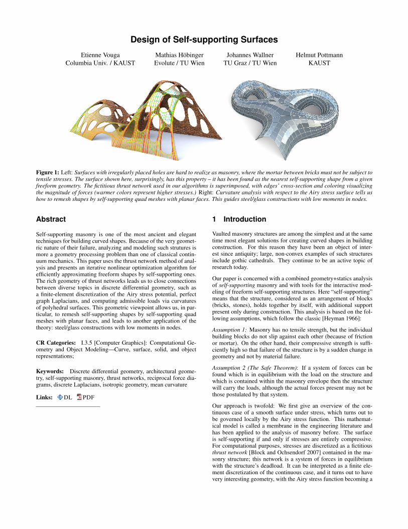
Figure 7: Interactive Edits. (a) shows aself-supporting thrust network – in fact itis a Koebe mesh as mentioned in §5. In(b) boundary conditions are defined andpillars have been added. Cutting alongthe highlighted edge and optimizing forthe self-supporting property results in themesh shown in (c).
(a) (b) (c) (d)
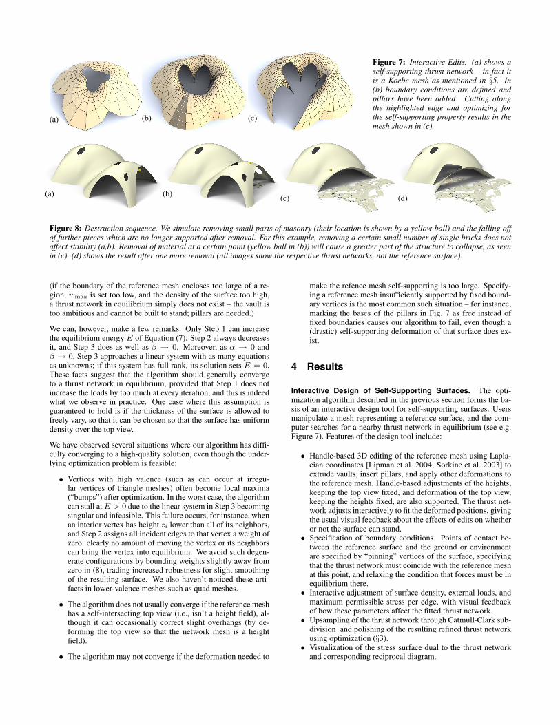
Figure 8: Destruction sequence. We simulate removing small parts of masonry (their location is shown by a yellow ball) and the falling offof further pieces which are no longer supported after removal. For this example, removing a certain small number of single bricks does notaffect stability (a,b). Removal of material at a certain point (yellow ball in (b)) will cause a greater part of the structure to collapse, as seenin (c). (d) shows the result after one more removal (all images show the respective thrust networks, not the reference surface).
(if the boundary of the reference mesh encloses too large of a re-gion, wmax is set too low, and the density of the surface too high,a thrust network in equilibrium simply does not exist – the vault istoo ambitious and cannot be built to stand; pillars are needed.)
We can, however, make a few remarks. Only Step 1 can increasethe equilibrium energy E of Equation (7). Step 2 always decreasesit, and Step 3 does as well as β → 0. Moreover, as α → 0 andβ → 0, Step 3 approaches a linear system with as many equationsas unknowns; if this system has full rank, its solution sets E = 0.These facts suggest that the algorithm should generally convergeto a thrust network in equilibrium, provided that Step 1 does notincrease the loads by too much at every iteration, and this is indeedwhat we observe in practice. One case where this assumption isguaranteed to hold is if the thickness of the surface is allowed tofreely vary, so that it can be chosen so that the surface has uniformdensity over the top view.
We have observed several situations where our algorithm has diffi-culty converging to a high-quality solution, even though the under-lying optimization problem is feasible:
• Vertices with high valence (such as can occur at irregu-lar vertices of triangle meshes) often become local maxima(“bumps”) after optimization. In the worst case, the algorithmcan stall atE > 0 due to the linear system in Step 3 becomingsingular and infeasible. This failure occurs, for instance, whenan interior vertex has height zi lower than all of its neighbors,and Step 2 assigns all incident edges to that vertex a weight ofzero: clearly no amount of moving the vertex or its neighborscan bring the vertex into equilibrium. We avoid such degen-erate configurations by bounding weights slightly away fromzero in (8), trading increased robustness for slight smoothingof the resulting surface. We also haven’t noticed these arti-facts in lower-valence meshes such as quad meshes.
• The algorithm does not usually converge if the reference meshhas a self-intersecting top view (i.e., isn’t a height field), al-though it can occasionally correct slight overhangs (by de-forming the top view so that the network mesh is a heightfield).
• The algorithm may not converge if the deformation needed to
make the refence mesh self-supporting is too large. Specify-ing a reference mesh insufficiently supported by fixed bound-ary vertices is the most common such situation – for instance,marking the bases of the pillars in Fig. 7 as free instead offixed boundaries causes our algorithm to fail, even though a(drastic) self-supporting deformation of that surface does ex-ist.
4 Results
Interactive Design of Self-Supporting Surfaces. The opti-mization algorithm described in the previous section forms the ba-sis of an interactive design tool for self-supporting surfaces. Usersmanipulate a mesh representing a reference surface, and the com-puter searches for a nearby thrust network in equilibrium (see e.g.Figure 7). Features of the design tool include:
• Handle-based 3D editing of the reference mesh using Lapla-cian coordinates [Lipman et al. 2004; Sorkine et al. 2003] toextrude vaults, insert pillars, and apply other deformations tothe reference mesh. Handle-based adjustments of the heights,keeping the top view fixed, and deformation of the top view,keeping the heights fixed, are also supported. The thrust net-work adjusts interactively to fit the deformed positions, givingthe usual visual feedback about the effects of edits on whetheror not the surface can stand.
• Specification of boundary conditions. Points of contact be-tween the reference surface and the ground or environmentare specified by “pinning” vertices of the surface, specifyingthat the thrust network must coincide with the reference meshat this point, and relaxing the condition that forces must be inequilibrium there.
• Interactive adjustment of surface density, external loads, andmaximum permissible stress per edge, with visual feedbackof how these parameters affect the fitted thrust network.
• Upsampling of the thrust network through Catmull-Clark sub-division and polishing of the resulting refined thrust networkusing optimization (§3).
• Visualization of the stress surface dual to the thrust networkand corresponding reciprocal diagram.

Figure 9: Stability Test. Left: Coloring and cross-section of edgesvisualize the magnitude of forces in a thrust network which is inequlibrium with this dome’s dead load. Right: When an additionalload is applied, there exists a corresponding compressive thrust net-work which is still contained in the masonry hull of the originaldome. This implies stability of the dome under that load. 14 m←−−−−−−−−−−−−−−−−−−−−−−−−−−−−−−→
shell thickness 0.1 m, ρ = 2, 500 kg/m3
11,000 kg
Figure 10: Stability test similar to Figure 9, but with a shell thickness of 1 m, in order to better visualize the way the thrust network starts toleave the masonry hull as the load increases. Additional loads are 0 kg, 5,000 kg, 10,000 kg, and 20,000 kg, resp., from left to right.
Examples. Top of the Lilium Tower: Consider the top portion ofthe steel-glass exterior surface of the Lilium Tower (being built inWarszaw, see Fig. 5). What is if we had wanted to build this sur-face out of masonry instead? This surface contains a concave partwith local minimum in its interior and so cannot possibly be self-supporting without modification. Given this surface as a referencemesh, our algorithm constructs a nearby thrust network in equilib-rium without the impossible feature. The user can then explore howediting the reference mesh – adding a pillar, for example – affectsthe thrust network and its deviation from the reference surface.
Example: Freeform Structure with Two Pillars. Suppose an archi-tect’s experience and intuition has permitted the design of a nearlyself-supporting freeform surface (Figure 6). Our algorithm revealsthose edits needed to make the structure sound – principally aroundthe entrance arch, and the area between the two pillars.
(a) (b)
Figure 11: A mesh with holes (a) requires large deformations toboth the top view and heights to render it self-supporting (b)
Example: Interactive Editing. Figure 7 shows an example of the de-sign and optimization workflow. Starting with a mesh, we first addpillars in the center and clean up the outer boundary (by fixing it tothe floor). A subsequent cut needs a further round of optimization.This surface is neither convex nor simply connected, and exhibits amix of boundary conditions, none of which cause our algorithm anydifficulty; it always finds a self-supporting thrust network near thedesigned reference mesh. The user is free to make edits to the refer-ence mesh, and the thrust network adapts to these edits, providingthe user feedback on whether these designs are physically realiz-able [we refer to the accompanying video for interactive buildingand editing of freeform self-supporting shapes].
Example: Destruction Sequence. In Figure 8 we simulate removingparts of masonry and the falling off of further pieces which are nolonger supported after removal. This is done by deleting the 1-neighborhood of a vertex and solving for a new thrust network in
compressive equilibrium close to the original reference surface. Wedelete those parts of the network which deviate too much and areno longer contained in the masonry hull, and iterate.
Example: Swiss Cheese. Cutting holes in a self-supporting surfaceinterrupts force flow lines and causes dramatic global changes tothe surface stresses, often to the point that the surface is no longerin equilibrium. Whether a given surface with many such holes canstand is far from obvious. Figure 11a shows such an implausibleand unstable surface; our optimization finds a nearby, equally im-plausible but stable surface without difficulty (Figs. 1, left and 11b).
Example: Stability Test: See Figures 9, 10 for a series of imageswhich visualize the effect of additional loads on a thrust network.
Example: Structural Glass. See Figure 16 for details on a self-supporting surface which is realized not as masonry, but as a steel/glass construction with glass as a structural element.
5 Special Self-Supporting Surfaces
PQ Meshes. Meshes with planar faces are of particular interestin architecture, so in this section we discuss how to remesh a giventhrust network in equilibrium such that it becomes a quad meshwith planar faces (again in equilibrium). If this mesh is realizedas a steel-glass construction, it is self-supporting in its beams alone,with no forces exerted on the glass (this is the usual manner of usingglass). The beams constitute a self-supporting structure which is inperfect force equilibrium (without moments in the nodes) if onlythe deadload is applied. (In such constructions, the restriction thatthe internal forces are compressive does not apply.)
((a) ((b) ((c)
Figure 12: Directly enforcing planarity of the faces of even avery simple self-supporting quad-mesh vault (a) results in a sur-face far removed from the original design (b). Starting instead froma remeshing of the surface with edges following relative principalcurvature directions yields a self-supporting, PQ mesh far morefaithful to the original (c).
Taking an arbitrary non-planar quad mesh and attempting naive, si-

Figure 13: Planar quad remeshing ofthe surface of Fig. 5. (a) Relative prin-cipal directions, found from eigenvec-tors of (∇2φ)−1∇2s. (b) Quad meshguided by principal directions is al-most planar and almost self-support-ing. (c) Small changes achieve bothproperties.
(a) (b) (c)
Figure 14: Planar quad remeshing ofthe surface of Figure 6. Left: Relativeprincipal directions. Right: The re-sult of optimization is a self-support-ing PQ mesh, which guides a moment-free steel/glass construction (interiorview, see also Fig. 1).
multaneous enforcement of planarity and static equilibrium – eitherby staggering a planarity optimization step every outer iteration, oradding a planarity penalty term to the position update – does notyield good results, as shown in Figure 12. Indeed, as we will seelater in this section, such a planar perturbation of a thrust networkis not expected to generally exist.
Consider a planar quad mesh S with vertices vij = (xij , yij , sij)which approximates a given continuous surface s(x, y). It is knownthat S must approximately follow a network of conjugate curves inthe surface (see e.g. [Liu et al. 2006]). We can derive this conditionin an elementary way as follows: Using a Taylor expansion, wecompute the volume of the convex hull of the quadrilateral vij ,vi+1,j , vi+1,j+1, vi,j+1, assuming the vertices lie exactly on thesurface s(x, y). This results in
vol = 16
det(a1,a2) ·`(a1)T ∇2sa2
´+ · · · ,
where a1 =`xi+1,j−xijyi+1,j−yij
´, a2 =
`xi,j+1−xijyi,j+1−yij
´,
and the dots indicate higher order terms. We see that planarity re-quires (a1)T ∇2sa2 = 0. In addition to the mesh S approximatingthe surface s(x, y), the corresponding polyhedral Airy surface Φmust approximate φ(x, y); thus we get the conditions
(a1)T ∇2s a2 = (a1)T ∇2φ a2 = 0.
a1,a2 are therefore eigenvectors of (∇2φ)−1∇2s. In view of §2.3,a1,a2 indicate the principal directions of the surface s(x, y) rela-tive to φ(x, y).
In the discrete case, where s, φ are not given as continuous surfaces,but are represented by a mesh in equilibrium and its Airy mesh, weuse the techniques of Schiftner [2007] and Cohen-Steiner and Mor-van [2003] to approximate the Hessians ∇2s, ∇2φ, compute prin-cipal directions as eigenvectors of (∇2φ)−1∇2s, and subsequentlyfind meshes S,Φ approximating s, φwhich follow those directions.Global optimization can now polish S,Φ to a valid thrust networkwith discrete stress potential, where before it failed: we do so bytaking the planarity energy
Pf (2π − θf )2, where the sum runs
over faces and θf is the sum of the interior angles of face f , lin-earizing it at every iteration, and adding it to the objective functionof the position update (Step 3). Convexity of Φ ensures that S isself-supporting.
Note that for each Φ, the relative principal curvature directions givethe unique curve network along which a planar quad discretization
of a self-supporting surface is possible. Other networks won’t work(see Figure 12). Figures 13 and 14 further illustrate the result ofapplying this procedure to self-supporting surfaces.
Remark: When remeshing a given shape by planar quad meshes, weknow that the circular and conical properties require that the meshfollows the ordinary, Euclidean principal curvature directions [Liuet al. 2006]. It is remarkable that the self-supporting property in asimilar manner requires us to follow certain relative principal direc-tions. Practictioners’ observations regarding the beneficial staticsproperties of principal directions can be explained by this analogy,because the relative principal directions are close to the Euclideanones, if the stress distribution is uniform and ‖∇s‖ is small.
Koenigs Meshes. Given a self-supporting thrust network S withstress surface Φ, we ask the question: Which vertical perturbationS+R is self-supporting, with the same loads as S? As to notation,all involved meshes S,R,Φ have the same top view, and arithmeticoperations refer to the respective z coordinates si, ri, φi of vertices.
The condition of equal loads then is expressed as ∆φ(s+r) = ∆φsin terms of Laplacians or as Hrel
S = HrelS+R in terms of mean cur-
vature, and is equivalent to ∆φr = 0, i.e., HrelR = 0. So R is a
minimal surface relative to Φ. While in the triangle mesh case thereare enough degrees of freedom for nontrivial solutions, the case ofplanar quad meshes is more intricate: Polar polyhedraR∗,Φ∗ haveto be Christoffel duals of each other [Pottmann and Liu 2007], as il-lustrated by Figure 4. Unfortunately not all quad meshes have sucha dual; the condition is that the mesh is Koenigs, i.e., the derivedmesh formed by the intersection points of diagonals of faces againhas planar faces [Bobenko and Suris 2008].
Koebe meshes. An interesting special case occurs if Φ is aKoebe mesh of isotropic geometry, i.e., a PQ mesh whose edgestouch the Maxwell paraboloid. Since Φ approximates the Maxwellparaboloid, we get 2K(vi)H
rel(vi) ≈ 1 and Φ consequently isself-supporting for unit load. Applying the Christoffel dual con-struction described above yields a minimal mesh R, and meshesΦ + αR which are self-supporting for unit load (see Figure 15).
6 Conclusion and Future Work
Conclusion. This paper builds on relations between statics andgeometry, some of which have been known for a long time, and

Φ + αR
Φ
R
Figure 15: Left: A “Koebe” mesh Φ is self-supporting for unit deadload. An family of self-supporting meshes with the same top view isdefined by Sα = Φ + αR, where R is chosen as Φ’s Christoffel-dual. The right hand image shows a different example of the sameconnectivity.
connects them with newer methods of discrete differential geome-try, such as discrete Laplace operators and curvatures of polyhedralsurfaces. We were able to find efficient ways of modeling self-supporting freeform shapes, and provide architects and engineerswith an interactive tool for evaluating the statics of freeform ge-ometries. The self-supporting property of a shape is directly rele-vant for freeform masonry. The actual thrust networks we use forcomputation are relevant e.g. for steel constructions, where equilib-rium of deadload forces implies absence of moments. This theoryand accompanying algorithms thus constitute a new contribution toarchitectural geometry, connecting statics and geometric design.
Acknowledgments. This work was very much inspired byPhilippe Block’s plenary lecture at the 2011 Symposium on Geom-etry Processing in Lausanne. Several illustrations (the destructionsequence of Fig. 8 and the maximum load example of Fig. 9) havereal-world analogues on his web page at ETH Zurich, see [Block2011] and [Davis et al. 2011].
We would also like to thank Florin Isvoranu and Alexander Schift-ner for their help and input during preparation of this paper; the de-velopers of the OpenMesh, Ipopt, Eigen, and BCLS software pack-ages used in our implementation; and Miklos Bergou, Eitan Grin-spun, Danny Kaufman, and Niloy Mitra for their advice and sugges-tions on early drafts of the paper. This work was funded in part bythe NSF (CMMI-11-29917, IIS-11-17257, IIS-10-48948, IIS-09-16129, CCF-06-43268) and generous gifts from Adobe, ATI, Au-todesk, mental images, NVIDIA, Side Effects Software, the WaltDisney Company, and Weta Digital. The work of Helmut Pottmannand Mathias Hobinger was supported by the Austrian Science Fund(FWF) through grants No. P9206-N12 and P23735-N13 and the Eu-ropean Communitys 7th Framework Programme under grant agree-ment 230520 (ARC).
Future Work. There are several directions of future research. Oneis to incorporate non-manifold meshes, which occur naturally whene.g. supporting walls are introduced. It is also obvious that non-ver-tical loads, e.g. wind load, play a role. The surfaces produced byour algorithm are the solutions of discrete elliptic boundary valueproblems and so tend to be smooth; another avenue for future workis modification of the discretization to allow for self-supporting sur-faces with sharp features. There are also some directions to pur-sue in improving the algorithms, for instance adaptive remeshing inproblem areas. Probably the interesting connections between stat-
ics and geometry are not yet exhausted: on the one hand we ex-pect that interesting new geometry arises from questions of statics,on the other hand we would like to propose the geometrization ofproblems as a general solution paradigm.
References
ANDREU, A., GIL, L., AND ROCA, P. 2007. Computational anal-ysis of masonry structures with a funicular model. J. Engrg.Mechanics 133, 473-480.
ASH, P., BOLKER, E., CRAPO, H., AND WHITELEY, W. 1988.Convex polyhedra, Dirichlet tessellations, and spider webs. InShaping space (Northampton 1984). Birkhauser, 231–250.
BARNES, M. R. 2009. Form finding and analysis of tension struc-tures by dynamic relaxation. Int. J. Space Struct. 14, 2, 89–104.
BLOCK, P., AND LACHAUER, L. 2011. Closest-fit, compression-only solutions for free form shells. In IABSE — IASS 2011 Lon-don Symposium, Int. Ass. Shell Spatial Structures. [electronic].
BLOCK, P., AND OCHSENDORF, J. 2007. Thrust network analysis:A new methodology for three-dimensional equilibrium. J. Int.Assoc. Shell and Spatial Structures 48, 3, 167–173.
BLOCK, P. 2009. Thrust Network Analysis: Exploring Three-dimensional Equilibrium. PhD thesis, Massachusetts Instituteof Technology.
BLOCK, P., 2011. Project webpage at http://block.arch.ethz.ch/projects/freeform-catalan-thin-tile-vaulting.
BOBENKO, A., AND SURIS, YU. 2008. Discrete differential geom-etry: Integrable Structure. No. 98 in Graduate Studies in Math.American Math. Soc.
BOBENKO, A., POTTMANN, H., AND WALLNER, J. 2010. Acurvature theory for discrete surfaces based on mesh parallelity.Math. Annalen 348, 1–24.
COHEN-STEINER, D., AND MORVAN, J.-M. 2003. RestrictedDelaunay triangulations and normal cycle. In Proc. 19th Symp.Computational Geometry, ACM, 312–321.
DAVIS, L., RIPPMANN, M., PAWLOFSKY, T., AND BLOCK, P.2011. Efficient and expressive thin-tile vaulting using cardboardformwork. In IABSE — IASS 2011 London Symposium, Int. Ass.Shell Spatial Structures. [electronic].
FRATERNALI, F., ANGELILLO, M., AND FORTUNATO, A. 2002.A lumped stress method for plane elastic problems and the dis-crete-continuum approximation. Int. J. Solids Struct. 39, 6211–6240.
FRATERNALI, F. 2010. A thrust network approach to the equi-librium problem of unreinforced masonry vaults via polyhedralstress functions. Mechanics Res. Comm. 37, 2, 198 – 204.
FRIEDLANDER, M. P., 2007. BCLS: Bound constrained leastsquares. http://www.cs.ubc.ca/∼mpf/bcls.
GIAQUINTA, M., AND GIUSTI, E. 1985. Researches on the equi-librium of masonry structures. Archive for Rational Mechanicsand Analysis 88, 4, 359–392.
GREEN, A., AND ZERNA, W. 2002. Theoretical Elasticity. Dover.Reprint of the 1968 edition.
GRUNDIG, L., MONCRIEFF, E., SINGER, P., AND STROBEL, D.2000. A history of the principal developments and applications

Figure 16: Glass as a structural element can support stresses up to, say, 30 MPa.We propose steel/glass constructions which utilize the structural properties of glassby first solving for a self-supporting thrust network such that forces do not exceedthe maximum values, and subsequent remeshing of this surface by a planar quadmesh (not necessarily self-supporting itself). Since this surface is very close to aself-supporting shape, joints will experience low bending and torsion moments.
of the force density method in Germany 1970–1999. In 4th Int.Coll. Computation of Shell & Spatial Structures.
HEYMAN, J. 1966. The stone skeleton. Int. J. Solids Structures 2,249–279.
HEYMAN, J. 1995. The Stone Skeleton: Structural Engineering ofMasonry Architecture. Cambridge University Press.
HEYMAN, J. 1998. Structural Analysis: A Historical Approach.Cambridge University Press.
KILIAN, A., AND OCHSENDORF, J. 2005. Particle-spring sys-tems for structural form finding. J. Int. Assoc. Shell and SpatialStructures 46, 77–84.
KOTNIK, T., AND WEINSTOCK, M. 2012. Material, form andforce. Architectural Design 82, 104–111.
LINKWITZ, K., AND SCHEK, H.-J. 1971. Einige Bemerkungenzur Berechnung von vorgespannten Seilnetzkonstruktionen. In-genieur-Archiv 40, 145–158.
LIPMAN, Y., SORKINE, O., COHEN-OR, D., LEVIN, D., ROSSI,C., AND SEIDEL, H. 2004. Differential coordinates for in-teractive mesh editing. In Shape Modeling Applications, 2004.Proceedings. IEEE, 181–190.
LIU, Y., POTTMANN, H., WALLNER, J., YANG, Y.-L., ANDWANG, W. 2006. Geometric modeling with conical meshesand developable surfaces. ACM Trans. Graphics 25, 3, 681–689.Proc. SIGGRAPH.
LIVESLEY, R. K. 1992. A computational model for the limit anal-ysis of three-dimensional masonry structures. Meccanica 27,161–172.
O’DWYER, D. 1998. Funicular analysis of masonry vaults. Com-puters and Structures 73, 187–197.
PAIGE, C. C., AND SAUNDERS, M. A. 1975. Solution of sparseindefinite systems of linear equations. SIAM J. Num. Analysis12, 617–629.
POTTMANN, H., AND LIU, Y. 2007. Discrete surfaces in isotropicgeometry. In Mathematics of Surfaces XII, M. Sabin and J. Win-kler, Eds. Springer, 341–363.
POTTMANN, H., LIU, Y., WALLNER, J., BOBENKO, A., ANDWANG, W. 2007. Geometry of multi-layer freeform structuresfor architecture. ACM Trans. Graphics 26, 3, #65,1–11. Proc.SIGGRAPH.
SCHIFTNER, A., AND BALZER, J. 2010. Statics-sensitive layoutof planar quadrilateral meshes. In Advances in Architectural Ge-ometry 2010, C. Ceccato et al., Eds. Springer, Vienna, 221–236.
SCHIFTNER, A. 2007. Planar quad meshes from relative principalcurvature lines. Master’s thesis, TU Wien. http://dmg.tuwien.ac.at/aschiftner/doc/diplomarbeit.pdf.
SORKINE, O., COHEN-OR, D., AND TOLEDO, S. 2003. High-pass quantization for mesh encoding. In Symposium Geometryprocessing, L. Kobbelt, P. Schroder, and H. Hoppe, Eds. Euro-graphics Assoc., 42–51.
VAN MELE, T., AND BLOCK, P. 2011. A novel form findingmethod for fabric formwork for concrete shells. J. Int. Assoc.Shell and Spatial Structures 52, 217–224.
WACHTER, A., AND BIEGLER, L. T. 2006. On the implementa-tion of a primal-dual interior point filter line search algorithm forlarge-scale nonlinear programming. Math. Progr. 106, 25–57.
WARDETZKY, M., MATHUR, S., KALBERER, F., AND GRIN-SPUN, E. 2007. Discrete Laplace operators: No free lunch.In Symposium on Geometry Processing, A. Belyaev and M. Gar-land, Eds. Eurographics Assoc., 33–37.
WHITING, E., OCHSENDORF, J., AND DURAND, F. 2009. Proce-dural modeling of structurally-sound masonry buildings. ACMTrans. Graphics 28, 5, #112,1–9. Proc. SIGGRAPH Asia.