Design of Remedial Support in Belt Drift, Moranbah...
43
Design of Remedial Support in Belt Drift, Moranbah North Mine Ismet Canbulat
Transcript of Design of Remedial Support in Belt Drift, Moranbah...

Design of Remedial Support in Belt Drift,
Moranbah North Mine
Ismet Canbulat

Outline
Summary of rib fall at Moranbah North MineGeology in and around the driftsLessons learntRemedial work carried out
Immediate Long-term
Design of long term remedial support designSystems implemented following the rib fallAcknowledgementsMegabolt specs

Rib Fall
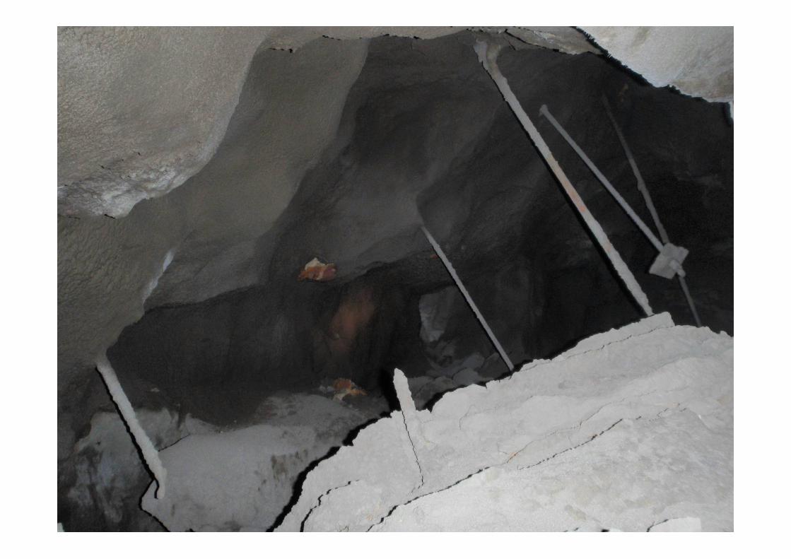
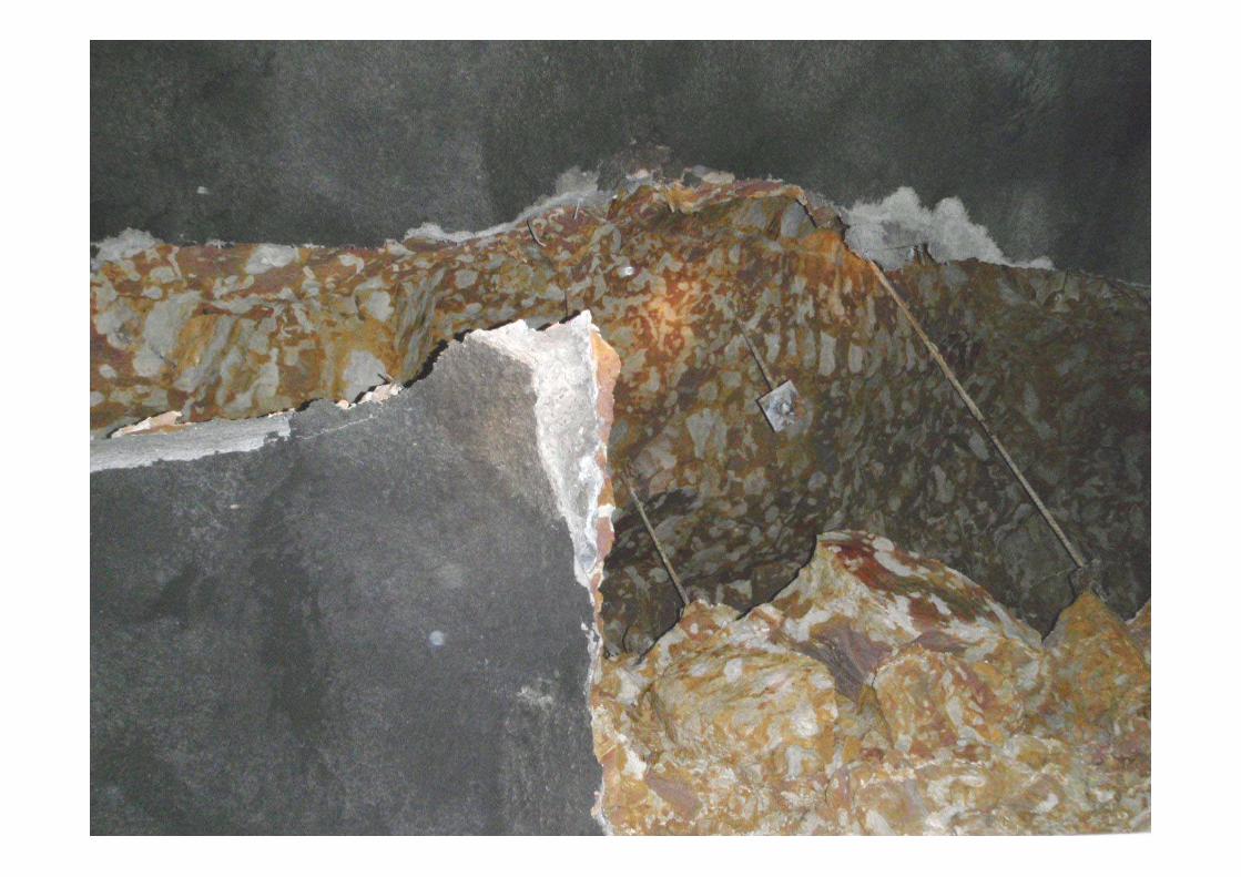
On Sunday 18/01/09, a section of the rib, located within a tuff/claystone unit, in the conveyor drift failed at Moranbah North Mine.
Material that had been previously contained by the strata support (roof bolts and shotcrete) slumped and came to rest against the drift conveyor after approximately 13 years of development.
Stop the production and development for 7 days

Rib Fall
Rib Fall

Rib Fall
Rib Fall

Rib Fall

Rib Fall

Dimensions of the Fall
FLOOR
ROOF BeltStructure
Total Weight = 334.6 tonnesSupport Design SF = 2.4

Original Support Design

Geology
Steel arches installed

Geology

Geology

Geology

Lessons Learnt
When the rock mass is weak, use grout not resin to fully encapsulate
Monitor encapsulation length
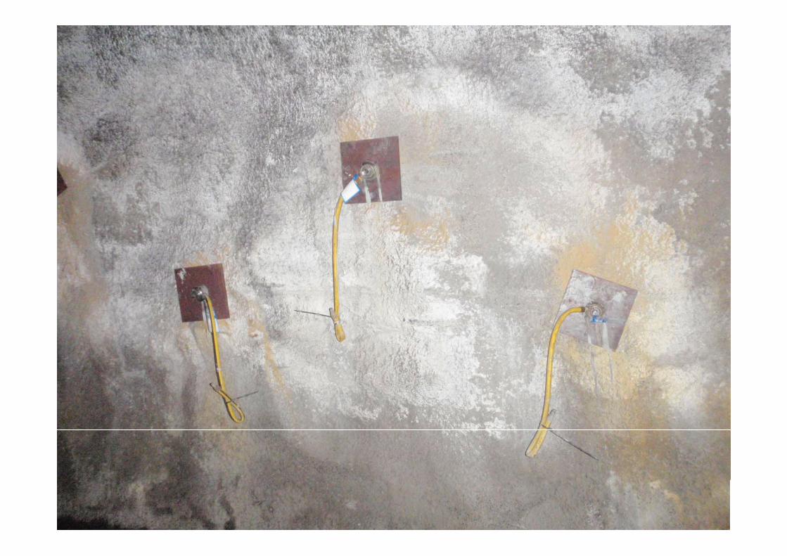
Use corrosion protective cables/bolts in prone area
Do not rely only on shotcrete visual monitoring only
Respond the warnings in a timely manner
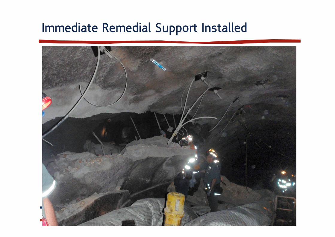
Immediate Remedial Support Installed

Risk Assessment and Investigation Concluded
The adequacy of the support in the drifts should be evaluated
The monitoring systems we use should be evaluated
The corrosion impact on the integrity on the previously installed areas should evaluated
Our response to defect reports should be improved
All critical areas should routinely be reviewed by the geotechnical engineers
Develop TARPs for the drifts

Remedial Support Design
Overburden(claystone/tuff/soil)
Floor(weathered basalt)
Drift
Roof bolts(not installed at this stage)
Floor concrete
22m
18m
46.7m
Overburden(claystone/tuff/soil)
Floor(weathered basalt)
Drift
Roof bolts(not installed at this stage)
Floor concrete
22m
18m
46.7m

Remedial Support Design
6.700 m
2.900 m
0.300 m
5.050 m
2.150 m

Remedial Support Design
Step 1:• No mining – virgin
conditions
Step 2:• Tunnel is excavated
Step 3:• 50 mm thick shotcrete
is applied
Step 4:• Bolts are installed and • Another 50 mm thick
layer of shotcrete is applied
Step 5:• Floor is concreted• Remedial support is
installed

Remedial Support Design
TotalDisplacementm
0.0000
0.0020
0.0040
0.0060
0.0080
0.0100
0.0120
0.0140
0.0160
0.0180
0.0200
0.0220
0.0240
-20
24
68
-8 -6 -4 -2 0 2 4 6 8 10 12 14
Total displacement
Shotcrete failure

Remedial Support Design
MaximumShear Strain
0.00e+000
1.00e-003
2.00e-003
3.00e-003
4.00e-003
5.00e-003
6.00e-003
7.00e-003
8.00e-003
9.00e-003
1.00e-002
1.10e-002
1.20e-002
-20
24
68
-8 -6 -4 -2 0 2 4 6 8 10 12 14
Maximum shear strain
Possible failure planes following the failure of shotcrete

Remedial Support Design
Bolt numbers
1
2
3
4
5
6 7
8
9
10
11
12
13

Remedial Support Design
Axial load on selected bolts
0
0.02
0.04
0.06
0.08
0.1
0.12
0 0.5 1 1.5 2 2.5 3 3.5
Distance [m]
Axi
al F
orce
[MN
]
Bolt 1 Stage 5 Bolt 4 Stage 5 Bolt 13 Stage 5

Numerical Modelling Strategy
Back analysis of the fall
2 cable pattern
4 cable pattern
5 cable pattern
6 cable pattern
7 cable pattern
Increased thickness of shotcrete
Various other combinations of shotcrete

Remedial Support Design1.
4m
2.1m
1.0m
Floor
Roof
1.0m

Remedial Support Design
Remedial Support Design

Remedial Support Design
Defect Reporting System
An established (quantitative) easy to use reporting system.
Eliminate human factor from making critical decisions with regard to response time.
Simple, accurate decision making process with regard to prioritising the defect maintenance.
Accurate data recording system.
Simple, monthly defect reporting system.

Defect Reporting System
Input
Exposure
Risk &Response
Number of People in this section (both shifts)
Time of stay of people (minute)
Number of shifts Width Length
Risk to Development
(1), LW (2), Both (3)
Condition of defect (Low,
Moderate, High)
1 5 3 1 1 1 Low20 5 3 1 1 1 Low100 5 3 1 1 1 Low
Total hours per year
ExposureArea occupied by
miners in day shift
Constant Prob. of Failure
Prob of annual occurrence of a FOG accident
Total Stopage (Days)
Hourly LW/Dev stopage cost
Total Stopage
Cost
8760 75 1 0.1 2.6E-06 0.13101254 52083.33333 163765.678760 75 20 0.1 5.1E-05 0.13101254 52083.33333 163765.678760 75 100 0.1 2.6E-04 0.13101254 52083.33333 163765.67
H&S Risk Category
Finacial Risk
CategoryPriority (3 Levels)
Response time - Ismet
- 7/5/2009Low Low Low 90 days
Moderate Low Moderate 35 DaysHigh Low High 21 Days

Evaluation of Monitoring System
Visual monitoring (including routine deputy and geotechnical inspections)
Tell-tales
GEL extensometers
Sonic probe extensometers
Borescope – Borehole camera
Borehole cameras (has been introduced only recently)
Seismic monitoring

GoafWarn
Warning lights and siren
Seismic geophone Start switch Standard nut for installation on roof bolts
Warning lights and siren
Seismic geophone Start switch Standard nut for installation on roof bolts

Support Standards (Corrosion Protection)

Further Systems Implemented
Routine geotechnical reviews of the critical areas
TARPs for drifts have been developed and implemented
Quality control procedures for the remedial support has been developed and will be implemented shortly

Acknowledgement
Anglo Coal Australia and Moranbah North Mines are
acknowledged to allow me to present this presentation

MegaboltMegabolt
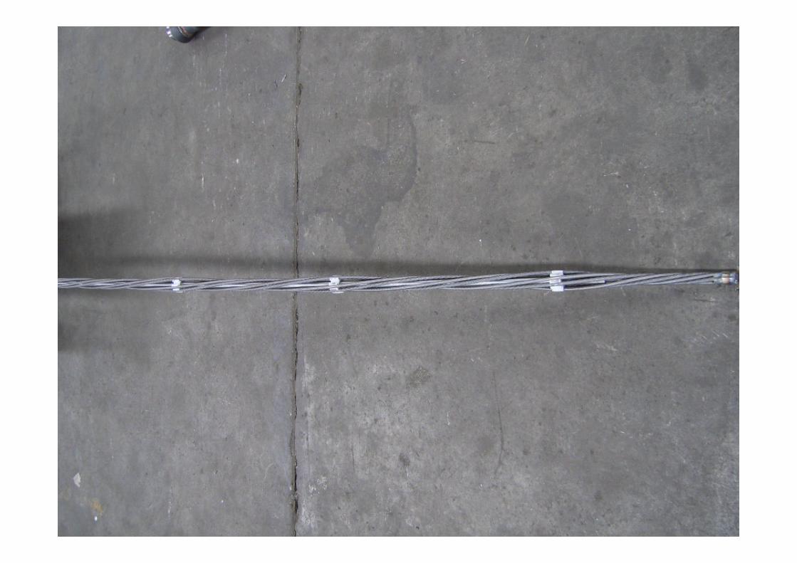
Megabolt

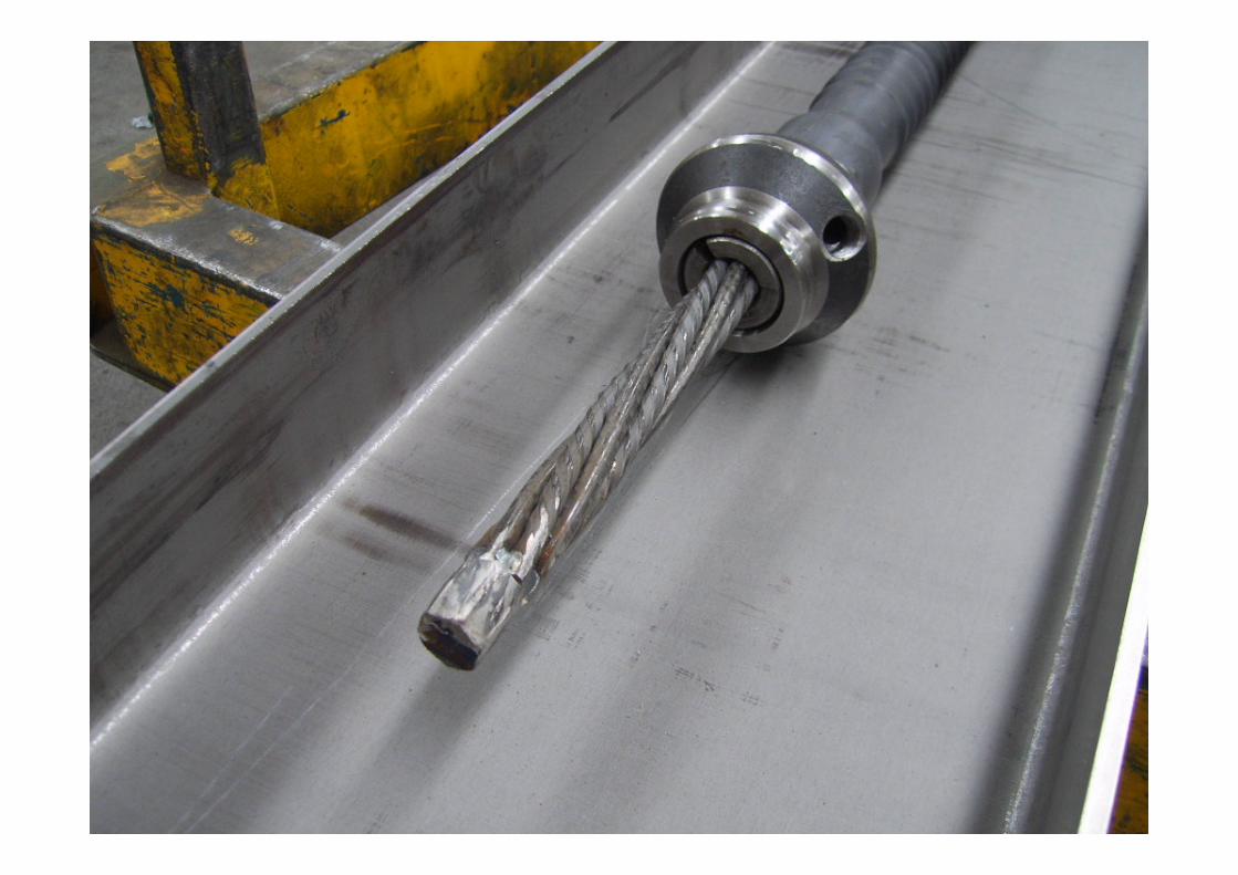
Megabolt

Megabolt

Megabolt