
Optical fiber communications__principles_and_practice__3rd_edition_
Sensors & Transducers, Vol. 156, Issue 9, September 2013, pp. 40-47
40
SSSeeennnsssooorrrsss &&& TTTrrraaannnsssddduuuccceeerrrsss
© 2013 by IFSAhttp://www.sensorsportal.com
Design of Reflective Optical Fiber Current Sensor Based on Improved Phase Modulation
Yajun WANG, Xuemei GUO
Xinxiang University, Henan Xinxiang, 453003, China
Tel.: 13663900097 E-mail: [email protected]
Received: 2 July 2013 /Accepted: 25 August 2013 /Published: 30 September 2013 Abstract: Full optical fiber current sensor phase modulation is the use of magnetic field made the refraction different of left-handed and right-handed circularly polarized light, and the linearly polarized light can be decomposed into a left-handed and right-handed circularly polarized light. The paper proposes research and design of reflective optical fiber current sensor based on improved phase modulation. This paper analyzes the current sensor reflective polarization of light changes, and using the Jones matrix analysis method to establish a reflective fiber optic current sensor model. Design of reflection type optical fiber current sensor model can improve the sensitivity of optical fiber current sensor. Copyright © 2013 IFSA. Keywords: Optical fiber current sensor, Phase modulation, Reflective optical sensors. 1. Introduction
Optical fiber current sensor since, has been attention. The existing optical fiber current sensor in the sensor head which is different can be divided into optical fiber current sensor, bulk glass optical fiber current sensor and a hybrid fiber current sensor. The basic principle of bulk glass optical fiber current sensor is: using total reflection, the linear polarized light through a glass material internal multiple reflections, formed around the closed optical path through an electrical conductor.
Optical fiber sensor has the advantages of small volume, light weight, can do the non-contact, non-destructive in harsh environment and remote measurement. Also have the advantages of high sensitivity, good reliability, raw material silicon resources Wei Fu, anti-electromagnetic interference, corrosion resistance, high pressure resistance, good electrical insulation properties, bendable, explosion-proof, wide frequency band, and low loss. At the
same time, it also makes it easy to connect with the computer, the realization of intelligent and remote monitoring. To improve the effect on the traditional sensors, able to complete the difficult to accomplish even cannot finish task in many cases.
This paper describes the current measurement applications in high-strength fiber-optic current sensor has the following advantages: fiber-optic current sensor is not magnetic saturation, unlike the usual electromagnetic transformer dynamic range limited by the magnetic saturation effect; fiber-optic current sensors resistant to electromagnetic interference, low demands on the environment; fiber optic current sensors over a wide frequency band, resulting in high linearity response; fiber optic current sensor size is relatively small, relatively easy installation [1]. In short, the fiber-optic current sensor has many advantages, especially its insulation performance, small size, low cost, and frequency bandwidth, short response time, which can be used to measure DC, AC and pulse current, so under high
Article number P_1324
Sensors & Transducers, Vol. 156, Issue 9, September 2013, pp. 40-47
41
pressure is expected to become ideal sensor for the measurement of large currents.
The main disadvantage of phase modulation type optical fiber current sensor is: polarization optical fiber birefringence induced changes tend to drown Faraday rotation angle, so the measurement accuracy is reduced. In view of this situation, mainly to solve two: one is to improve the intrinsic birefringence of optical fiber, but managed to increase the Faraday rotation angle. To improve the inherent birefringence fiber rate methods have been proposed in the previous section, in this chapter, mainly to improve the Faraday rotation angle. When light by the Faraday rotator is placed in a magnetic field when facing the external observation, magnetic induction intensity, polarization direction of light always along with the magnetic field (H) constitute a right-handed helix direction to the direction of rotation, which has nothing to do with the direction of propagation of light.
When light waves along the forward and reverse direction two times through the Faraday rotator, whose polarization direction rotating angle is the superposition and not offset, this is the Faraday effect of rotation to irreversibility, called the nonreciprocal optical rotation. Using the nonreciprocal Faraday Effect, improvements are made on the structure, namely the reflection type optical fiber current sensor model. The paper put forward research and design of reflective optical fiber current sensor based on improved phase modulation. 2. Study on Phase Modulation Type
Optical Fiber Current Sensor
Full optical fiber current sensor phase modulation is the use of magnetic field made the refraction of left-handed and right-handed circularly polarized light is different, and the linearly polarized light can be decomposed into a left-handed and right-handed circularly polarized light, and transmit a distance, showed linear polarized light vibration surface rotates, the rotation angle depends on the propagation along the magnetic field direction of circularly polarized light and left-handed right-handed circularly polarized light refractive index difference. Phase generated so by measuring the polarization and right-handed circularly polarized light propagating a distance difference measurement, can also make the current.
Phase modulation sensor and its basic principle is to use the object to be measured to the sensitive element, make the sensitive components of the refractive index and propagation constant changes, resulting in optical phase changes, the interference fringes produced by two beams of monochromatic light changes, to determine the phase change in the amount of light by detecting the interference fringe variation, thus get the information of the measured object. Usually the photo elastic effect, the sound
pressure or vibration sensor using current, magnetic field sensor; magnetostrictive effect; using electrostrictive electric field, and the use of optical fiber voltage sensor Saigenake rotating angular velocity sensor effect (FOG). This kind of sensor is with high sensitivity. But because must use special fiber and high precision detection system, so the cost is high.
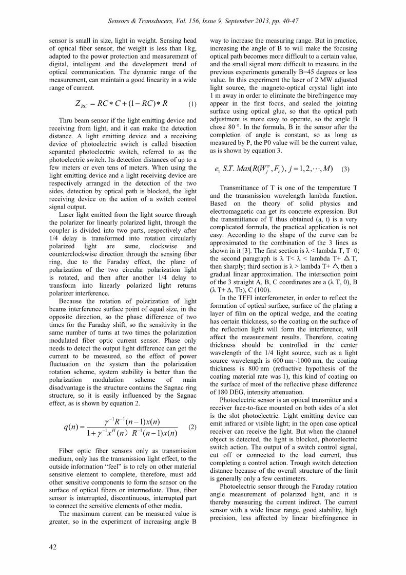
Optical fiber current sensor based on the Faraday Effect of magneto-optical materials, in a transparent medium optically isotropic, external magnetic field H can make the plane of polarization of polarized light propagating along the direction of the magnetic field in the medium surface is rotated, and the deflection angle can be determined by the analyzer. Its principle as shown in Fig. 1, B is two polarizer angle, theta into planar light through the angle of magneto-optic crystal after the occurrence.
Fig. 1. Design of phase modulation type optical fiber current sensor.
Optical fiber current sensor has the following advantages: (1) the insulation performance is very good, from materials: the use of optical fiber current sensor materials are mainly quartz fiber, an insulator itself is very good; (2) the core contains no fiber current sensor structure, because of the absence of magnetic saturation, ferromagnetic resonance and other issues, the measurement accuracy is improved. (3) the strong electromagnetic interference resistance, signal optical fiber current sensor to transmit by the light, with resistance to electromagnetic interference, measurement accuracy so that it can increase it.
The dimming control circuit for photoelectric coupler MOC3041 as the SCR drives; isolation and can realize the strong, weak [2]. MOC3041 has zero crossing detection circuit, when P0.O is low, the voltage output end 6 pin, 4 pin between the slightly zero, MOC304.1 internal bidirectional thyristor, trigger external thyristor T1 conduction. When PO.0 is high, and it is MOC304l internal bidirectional turn-off, and it is external thyristor T1 shutdown.
The low-pressure side not fiber current sensor has caused high risk for open circuit, thus eliminating the flammable and explosive traditional electromagnetic current transformer problem. Optical fiber current
Sensors & Transducers, Vol. 156, Issue 9, September 2013, pp. 40-47
42
sensor is small in size, light in weight. Sensing head of optical fiber sensor, the weight is less than l kg, adapted to the power protection and measurement of digital, intelligent and the development trend of optical communication. The dynamic range of the measurement, can maintain a good linearity in a wide range of current.
RRCCRCZ RC )1(
(1)
Thru-beam sensor if the light emitting device and receiving from light, and it can make the detection distance. A light emitting device and a receiving device of photoelectric switch is called bisection separated photoelectric switch, referred to as the photoelectric switch. Its detection distances of up to a few meters or even tens of meters. When using the light emitting device and a light receiving device are respectively arranged in the detection of the two sides, detection by optical path is blocked, the light receiving device on the action of a switch control signal output.
Laser light emitted from the light source through the polarizer for linearly polarized light, through the coupler is divided into two parts, respectively after 1/4 delay is transformed into rotation circularly polarized light are same, clockwise and counterclockwise direction through the sensing fiber ring, due to the Faraday effect, the plane of polarization of the two circular polarization light is rotated, and then after another 1/4 delay to transform into linearly polarized light returns polarizer interference.
Because the rotation of polarization of light beams interference surface point of equal size, in the opposite direction, so the phase difference of two times for the Faraday shift, so the sensitivity in the same number of turns at two times the polarization modulated fiber optic current sensor. Phase only needs to detect the output light difference can get the current to be measured, so the effect of power fluctuation on the system than the polarization rotation scheme, system stability is better than the polarization modulation scheme of main disadvantage is the structure contains the Sagnac ring structure, so it is easily influenced by the Sagnac effect, as is shown by equation 2.
)()1((1
)()1()(
11
11
nxnRnx
nxnRnq
H
)
(2)
Fiber optic fiber sensors only as transmission
medium, only has the transmission light effect, to the outside information “feel” is to rely on other material sensitive element to complete, therefore, must add other sensitive components to form the sensor on the surface of optical fibers or intermediate. Thus, fiber sensor is interrupted, discontinuous, interrupted part to connect the sensitive elements of other media.
The maximum current can be measured value is greater, so in the experiment of increasing angle B
way to increase the measuring range. But in practice, increasing the angle of B to will make the focusing optical path becomes more difficult to a certain value, and the small signal more difficult to measure, in the previous experiments generally B=45 degrees or less value. In this experiment the laser of 2 MW adjusted light source, the magneto-optical crystal light into 1 m away in order to eliminate the birefringence may appear in the first focus, and sealed the jointing surface using optical glue, so that the optical path adjustment is more easy to operate, so the angle B chose 80 °. In the formula, B in the sensor after the completion of angle is constant, so as long as measured by P, the P0 value will be the current value, as is shown by equation 3.
),,2,1,),((..1 MjFWRMaxTSe ej
(3)
Transmittance of T is one of the temperature T
and the transmission wavelength lambda function. Based on the theory of solid physics and electromagnetic can get its concrete expression. But the transmittance of T thus obtained (a, t) is a very complicated formula, the practical application is not easy. According to the shape of the curve can be approximated to the combination of the 3 lines as shown in it [3]. The first section is λ < lambda T, T=0;
△the second paragraph is λ T< λ < lambda T+ T, △then sharply; third section is λ > lambda T+ , then a
gradual linear approximation. The intersection point of the 3 straight A, B, C coordinates are a (λ T, 0), B (λ T+ Δ, Tb), C (100).
In the TFFI interferometer, in order to reflect the formation of optical surface, surface of the plating a layer of film on the optical wedge, and the coating has certain thickness, so the coating on the surface of the reflection light will form the interference, will affect the measurement results. Therefore, coating thickness should be controlled in the center wavelength of the 1/4 light source, such as a light source wavelength is 600 nm~1000 nm, the coating thickness is 800 nm (refractive hypothesis of the coating material rate was 1), this kind of coating on the surface of most of the reflective phase difference of 180 DEG, intensity attenuation.
Photoelectric sensor is an optical transmitter and a receiver face-to-face mounted on both sides of a slot is the slot photoelectric. Light emitting device can emit infrared or visible light; in the open case optical receiver can receive the light. But when the channel object is detected, the light is blocked, photoelectric switch action. The output of a switch control signal, cut off or connected to the load current, thus completing a control action. Trough switch detection distance because of the overall structure of the limit is generally only a few centimeters.
Photoelectric sensor through the Faraday rotation angle measurement of polarized light, and it is thereby measuring the current indirect. The current sensor with a wide linear range, good stability, high precision, less affected by linear birefringence in
Sensors & Transducers, Vol. 156, Issue 9, September 2013, pp. 40-47
43
optical fiber advantages; but there are large processing difficulty, the sensor head is fragile, high cost, and the inevitable reflection of light in the process of introducing reflective phase shift, so that the two orthogonal linear polarized into elliptical polarized light, thus affecting the performance of the system.
)1()1(
)1(
)!(!
!
kkkkk
(4)
In the optical path design and it is using the new
structure. The dark grey arrow line transmission path of the light in the sensor: the light emitted by the light source with optical fiber sensor by entering the self lens, reflected by the evaporation of reflecting film right-angle prism change for linearly polarized light into the magneto-optical crystal, polarization by a magnetic field modulation polarized light passes through a rectangular prism analyzer and the corresponding the other area through the selfoc lens fiber into the photoelectric detector.
Photoelectric detector choice to make the spectral responsively of R (λ) corresponding to the light peak wavelength, the best makes the peak response wavelength corresponding to the peak wavelength and light source, to achieve the maximum output. Therefore, selection of silicon PIN photodiode as photo detector, stable performance, its price is cheap, easy to use, especially in the 800 ~ 900 nm band photoelectric conversion efficiency is the highest, consistent with the working wavelength selected light source LED.
In this paper, dimming control according to the luminance calculated value; the P87LPC768 PWM output duty ratio is based on counting image CNSW register value and comparative mapping register CPSWn value determination, the PWM output remains high during the period of MCU clock pulse number (CNSW - CPSWn+1). Thus, the greater is the high level of CPSWn, the time is short, the dimming control circuit of T1 turn-on time is longer, the brightness of lighting equipment is higher; the brightness and lighting equipment is low, as is shown by equation 5.
TTTT Mmwmwmwmw ),(,),2,(),1,(:)(
(5)
The actual use of the sensor and the reader
(Demodulator) connection, emit white light diode light source reader of light from one end of the optical fiber connecting readouts incident, transmission connection to the Fabry-Perot sensor, and then ejected from the multimode fiber, irradiation in TFFI interferometer (wedge) surface. When the level of TFFI mobile and it is light point position will be different. Wedge two upper and lower surfaces are coated with a reflective film, which consists of the Fabry-Perot cavity [4]. When the reader launch white light was part of the first half of mirrors, the rest of
the white light passes through a Fabry-Perot cavity, and once again by second and a half mirror reflected back, two reflected light interference, the spectra of the original incident light is modulated.
Structural element photoelectric is switch and transmitter and optical fiber. Triangular reflector is launching device firm structure. It consists of a triangular pyramidal reflective material is very small, can make the beam accurately returned from the reflecting plate, has the practical significance. It can be in the optical axis of the 0 to 25 range change the emission angle, so that the beam is almost rays from a root, after reflection, or from the reflected ray returns.
Sagnac effect and Faraday effect are generating nonreciprocal phase shift, could not detected, resulting in the measurement error, reducing the stability of the system; the intrinsic birefringence of the sensing fiber is difficult to handle, because the fiber preparation process is not perfect, medium of impurities, defects, destruction of the axial symmetry of the fiber, and bending reasons to use when the inevitable, so that the inherent birefringence in the sensing fiber [5]. While the ordinary silica fiber Verdet constant is small, light polarization fiber birefringence induced changes tend to drown Faraday rotation angle, in order to improve the sensitivity, it is necessary to increase the number of sensing fiber ring, it will increase the intrinsic birefringence and bending caused by linear birefringence, so that the sensor sensitivity is much lower than the theoretical prediction value.
i
ii
yxdw
yxIyxdwyxF
)),((
),()),((),(
(6)
Light is an electromagnetic wave of high
frequency, the electric vector and magnetic vector and its direction are perpendicular to the direction of propagation of Yu Bo. Light disturbance is actually changed the intensity of electric field and magnetic field intensity of light. When light interacts with matter, theoretical and experimental results show that, the optical detector was an electrical vector instead of magnetic vector, so only need to consider the effect of electric field, so the electric vector to represent the light vector. Light waves are transverse wave, so the wave with polarization. Polarization of light can generally be divided into polarized light, natural light and polarized light. The size and direction of light vector rule changes called polarized light.
N
nimim nZnXZX
1
* )()(, )(
(7)
A linear polarizer coordinate system will be the
combination of these two components in the X, Y axis projection again, get the outgoing light of the two components A2 and B2, i.e. to make and B1cos
Sensors & Transducers, Vol. 156, Issue 9, September 2013, pp. 40-47
44
to make (1) Jones matrix line polarizer polarizer transmission shaft and the X shaft arranged forming angle. As shown in Fig. 2 builds XY coordinate system, the incident light of two components in the X, Y axis were A1 and B1, their online polarizer transmission direction projection. The incident light through a linear polarizer and it is components A1 and B1 along the light axis direction.
Optical fiber current sensor is based on the Faraday Effect to detect the current size of the optical sensor. The Faraday Effect refers to the linear polarized along the magnetic field direction through the medium of the polarization plane rotation phenomenon. The Jones matrix is an effective method of polarization and polarization of light.
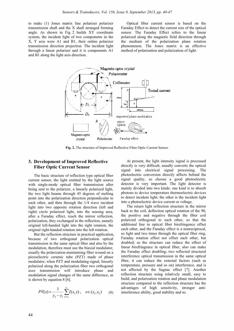
Fig. 2. The structure of Improved Reflective Fiber Optic Current Sensor. 3. Development of Improved Reflective
Fiber Optic Current Sensor
The basic structure of reflection type optical fiber current sensor, the light emitted by the light source with single-mode optical fiber transmission after being sent to the polarizer, a linearly polarized light, the two light beams through 45 degrees of melting point into the polarization direction perpendicular to each other, and then through the 1/4 wave incident light into two opposite rotation direction (left and right) circle polarized light, into the sensing area, after a Faraday effect, reach the mirror reflection, polarization, they exchanged in the reflection, namely original left-handed light into the right rotation, the original right-handed rotation into the left rotation.
But the reflection structure in practical application, because of two orthogonal polarization optical transmission in the same optical fiber and also by the modulation, therefore must use the biaxial modulator, usually the polarization-maintaining fiber wound on a piezoelectric ceramic tube (PZT) made of phase modulator, when PZT and modulating signal, linearly polarized along the polarization fiber two orthogonal axes transmission will introduce phase and modulation signal changes of the same difference, as is shown by equation 8 [6].
),(,),(
1)( 21
12
2
1
xxxyxIyy
xPVy
yy
(8)
At present, the light intensity signal is processed directly is very difficult, usually converts the optical signal into electrical signal processing. The photoelectric conversion directly affects behind the signal quality, so choose a good photoelectric detector is very important. The light detector is mainly divided into two kinds: one kind is to absorb photons to device temperature thermoelectric devices to detect incident light; the other is the incident light into a photoelectric device current or voltage.
The return light reflection structure in the mirror back to the coil, deflection optical rotation of the 90, the positive and negative through the fiber coil polarized orthogonal to each other, so that the additional line in optical fiber birefringence offset each other, and the Faraday effect is a nonreciprocal, so light and two times through the optical fiber ring, Faraday rotation effect not offset each other, but doubled, so the structure can reduce the effect of linear birefringence in optical fiber, also can make the Faraday effect doubling; two reflected structural interference optical transmission in the same optical fiber, it can reduce the external factors (such as temperature, pressure and so on) interference, and is not affected by the Sagnac effect [7]. Another reflection structure using relatively small, easy to build, and polarization rotation and phase modulation structure compared to the reflection structure has the advantages of high sensitivity, stronger anti-interference ability, good stability and so.
Sensors & Transducers, Vol. 156, Issue 9, September 2013, pp. 40-47
45
When linearly polarized along the magnetic field direction through the magnetic optical medium is arranged in the magnetic field, the polarization plane rotation, this phenomenon is called the Faraday effect, often called the Faraday effect. The essence of Faraday Effect for magnetic circular birefringence, namely the circularly polarized light through the Faraday Effect phase change. Because the linear polarized light can be expressed as the superposition of orthogonal circularly polarized beams of left and right of the, is cubic and isotropic materials Faraday effect, the rotation angle depends on the propagation along the magnetic field direction of the left-handed circularly polarized light and right-hand circularly polarized refractive index difference.
A white light source with the reader, from multimode fiber return light passes through the cylindrical lens into parallel light, be reflected in the TFFI interferometer on an inclined plane, and the lower surface of the TFFI to a CCD sensor is sensitive to light intensity. Hypothesis of monochromatic light irradiation on the surface of the wedge, is in the X direction of each point, wedge reflection light the surface and form the interference, and the lower surface of the transmission light is detected by the CCD.
The light emitting device and the light receiving device into the same device internal reflection type photoelectric switch, a reflecting plate in front of it, using the reflection principle complete the photoelectric control function is called reflection plate type (or mirror reflection type photoelectric switch). Under normal circumstances, a light emitting light is reflected back by the light reflecting plate is received; once the light path detecting object block, light receiving device does not receive the light, a photoelectric switch on the action, the output of a switch control signal.
After a circularly polarized light reflected by the original way back, again by the Faraday effect, and then by 1/4 wave conversion loop through polarized light, reflected light carrying phase difference information through the coupling device is transmitted to the photoelectric detector [8]. In the whole process, the two beams have undergone a polarization-maintaining optical fiber sensing fiber two axis and the left-handed and right-handed modes, so the light path is fully reciprocal. Phase difference depends on the size of magnetic field sensing region. Because the two beams of light have experienced two times of Faraday Effect, so the phase difference is 4 times the Faraday phase shift. Optical fiber current sensor, this structure, in other conditions are the same, the sensitivity is 4 times the deflection type optical fiber current sensor described earlier, 2 times the phase modulation type optical fiber current sensor.
1
0mod)1(2,,
j
j
L
lNlkljkj XhW
(9)
In order to further analysis the principle of reflection type optical fiber current sensor, analysis of y to change through the polarization state of the light signal (t). Output 1, 2 optical phase difference is: X (T) and for optical transmission time. Upon reflection, 1, 3 and 2, 4 exchange of fast and slow axis, so by the modulation of the phase modulation respectively, which makes y and X1 light source light polarizer P into a linearly polarized light, after 45 degree melting point after decomposing into two beams of light polarized vertically, the two beams of light by Faraday effect and produce a certain phase difference, return again when it is 45 degrees of melting point light, get up to the polarizer P four beam of light.
This paper designs the reflection type optical fiber current sensor model, improves the sensitivity of optical fiber current sensor, and from the angle of polarization of detailed analysis of each physical process, then the Jones matrix, theoretical calculation and Analysis on the conducted for reflection type optical fiber current sensor, the mathematical model of reflection type current sensor. 4. Design of Reflective Optical Fiber
Current Sensor based on Improved Phase Modulation
The theoretical foundation of optical fiber current
sensor technology, and from the angle of polarization of detailed analysis of each physical process, analyzes the changes of light polarization; then the Jones matrix, theoretical calculation and Analysis on the conducted for reflection type optical fiber current sensor [9]. Considering the characteristics and application of reflection type optical fiber current sensor of the environment and other factors, according to the source, the reflection type optical fiber current sensor system of photoelectric detector, phase shifter, phase modulator in various parts of the detailed design, device of reflection type optical fiber current sensor has been selected.
The diffuse reflection type photoelectric switch, detection and it is also provided with a light emitting device and a light receiving device, but there’s no reflector. Under normal circumstances, the light emitted by the light emitting device receiving device is not found. When the detection by blocking the light, and the back reflected light, light receiving device receives the light signal, the output of a switch signal.
Linearly polarized light is in the process of communication, the same light vector direction, the size of phase changes with light, then in the plane perpendicular to the propagation direction of the light vector, the endpoint trajectory is a straight line. Circularly polarized light is in the process of communication, the light vector of constant size, direction of rule changes, the endpoint of the path is a circle. All rules in the process of spreading light
Sensors & Transducers, Vol. 156, Issue 9, September 2013, pp. 40-47
46
vector magnitude and direction of elliptically polarized light, the light vector endpoints along the elliptical orbit rotates.
)()()(
1
1,,
*,,
*,1
q
rDriirViiVi mXGmXHmX
(10)
Jones matrix provides a method to express the
most succinct for polarization and polarization device. Using matrix arithmetic is to calculate the polarization components of the complex system of radio waves of state changes. But not to pursue specific physical meaning of each process, matrix representation method is to use a known as columns of a matrix to represent the Jones vector polarized light, through the matrix operation simple, convenient the plurality of polarized light after the superposition of new polarization, such as left and right circularly polarized light wave superposition, the results show that the synthesized light vector along the X axis of the linearly polarized light, the amplitude is 2 times of group polarization amplitude.
Polarization of polarized light can keep the influence of external conditions are not affected by the magnetic field outside, maintain the linear polarization and not into elliptical polarized light, polarized light the way for closed loop [10]. Only these two conditions are met, this paper firstly based on the theory of optical fiber current sensor, introduces the theory of Faraday effect; introduced Jones matrix method for the analysis of polarization system; Jones matrix is derived. Several main
polarization devices and it are as the foundation for establishing the system model.
Wavelengths of light emitted by the light source should be suitable for the requirements, in order to reduce the energy loss in optical fiber. The light source is to have enough brightness. In the optical fiber sensor is much also coherence on the light source is required. In addition, require light stability is good, can be at room temperature for the long-term and stable work, also asked the source of noise, convenient use etc. At the same time for the full optical fiber current sensor, the signal is usually through the communication is transmitted to the control room remote sensing or monitoring of optical fiber transmission, so the signal to be modulated in low loss window wavelength optical communications.
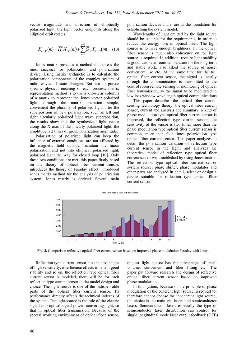
This paper describes the optical fiber current sensing technology theory, the optical fiber current sensor, current and analysis and summary; a kind of phase modulation type optical fiber current sensor is improved, the reflection type current sensor, the sensitivity of the sensor is two times more than the phase modulation type optical fiber current sensor is common, more than four times polarization type optical fiber current sensor. This paper analyzes in detail the polarization variation of reflection type current sensor in the light, and analyzes the theoretical model of reflection type optical fiber current sensor was established by using Jones matrix. The reflection type optical fiber current sensor system source, phase shifter, phase modulator and other parts are analyzed in detail, select or design a device suitable for reflection type optical fiber current sensor.
Fig. 3. Comparison reflective optical fiber current sensor based on improved phase modulation Faraday with Jones.
Reflection type current sensor has the advantages of high sensitivity, interference effects of small, good stability and so on, the reflection type optical fiber current sensor is modeled, there will be for each reflection type current sensor in the model design and choice. The light source is one of the indispensable parts of the optical fiber current sensor. Its performance directly affects the technical indexes of the system. The light source is the role of the electric signal into optical signal power, converting light, so that in optical fiber transmission. Because of the special working environment of optical fiber sensor,
request light source has the advantages of small volume, convenient and fiber fitting etc. The paper put forward research and design of reflective optical fiber current sensor based on improved phase modulation.
In this system, because of the principle of phase modulation of the coherent light source, a request to, therefore cannot choose the incoherent light source; the choice is the main gas lasers and semiconductor lasers. Semiconductor laser, especially the type of semiconductor laser distribution can control for single longitudinal mode laser output feedback (DFB)
Sensors & Transducers, Vol. 156, Issue 9, September 2013, pp. 40-47
47
performance is good, has the certain coherence and high stability, is an ideal light source for optical fiber current sensor system. 5. Conclusions
In the optical system, the phase delay can be used to realize optical fiber polarization controller. The polarization controller refers to the arbitrary input polarization state into any desired output polarization state. Fiber polarization controller usually used is photo elastic effect to change in the birefringence fiber, the fiber optical polarization control.
In the design of reflective fiber optic current sensor in the delay of the scheme is: in polarization-maintaining optical fiber exit end, will be a certain length of polarization-maintaining fiber torsion angle, realize the linearly polarized light conversion to a circularly polarized light. The advantages of this method are: between optical fiber and optical fiber sensor can be used welding method to directly link, make the whole system structure is simple, easy to debug. References [1]. Peng He, Zhen Zhou, Yong Qin, Fiber optic sensor
technology for measuring soybean milk concentration in tofu making, Journal of Convergence Information Technology, Vol. 8, No. 2, 2013, pp. 580-586.
[2]. Yu A-Long, Study on non-linearity mode building method based on Lagurre orthogonal polynomial basis functions neural network for Eddy current sensor, International Journal of Advancements in
Computing Technology, Vol. 4, No. 21, 2012, pp. 574-581.
[3]. Xiaoyan Kuai, Haixin Sun, Weijie Shen, En Cheng, Qi Jie, Peak-to-average power ratio reduction in underwater acoustic CE-OFDM system by phase modulation, Journal of Convergence Information Technology, Vol. 7, No. 9, 2012, pp. 380-386.
[4]. Dai Zhiyong, Lin Hui, Sun Xinxin, Modified vector control of five-phase PMSM drives for aircraft all-electric braking system, International Journal of Digital Content Technology & its Application, Vol. 7, No. 4, 2013, pp. 717-725.
[5]. Qinghui Zhang, Zenggang Xiong, Gang Liu, Noise elimination of vibration signal of distributed optical fiber-sensing system based on wavelet analysis, International Journal of Digital Content Technology & its Application, Vol. 5, No. 10, 2011, pp. 315-321.
[6]. Xiaoan Bao, Lingling Zhao, Jiangang Jin, Intelligent transport control system based on PIC single chip, International Journal of Advancements in Computing Technology, Vol. 4, No. 10, 2012, pp. 99-108.
[7]. Peng Gao, The application of distributed optical fiber sensing in seepage flow monitoring system, International Journal of Digital Content Technology & its Application, Vol. 6, No. 12, 2012, pp. 175-181.
[8]. WANG-Yong Jiao, LIANG-Lei, Realizing optical refractive index sensor by using the nano-fiber, International Journal of Digital Content Technology & its Application, Vol. 7, No. 6, 2013, pp. 300-308.
[9]. Jingwen Tian, Meijuan Gao, Guangshuang Ge, In-line measurement system of bore well mud viscosity based on multisensor data fusion with wavelet neural network, International Journal of Advancements in Computing Technology, Vol. 5, No. 5, 2013, pp. 1011-1018.
[10]. De En, Changsheng Zhou, Xiaolong Shi, Research of optic-fiber pressure sensor based on MOEMS, International Journal of Digital Content Technology & its Application, Vol. 7, No. 7, 2013, pp. 627-634.
___________________
2013 Copyright ©, International Frequency Sensor Association (IFSA). All rights reserved. (http://www.sensorsportal.com)


