Design of highly efficient coal-based integrated ...
13
UC Irvine UC Irvine Previously Published Works Title Design of highly efficient coal-based integrated gasification fuel cell power plants Permalink https://escholarship.org/uc/item/3r14b88j Journal Journal of Power Sources, 195(17) ISSN 0378-7753 Authors LI, M Rao, AD Brouwer, J et al. Publication Date 2010-09-01 DOI 10.1016/j.jpowsour.2010.03.045 Copyright Information This work is made available under the terms of a Creative Commons Attribution License, availalbe at https://creativecommons.org/licenses/by/4.0/ Peer reviewed eScholarship.org Powered by the California Digital Library University of California
Transcript of Design of highly efficient coal-based integrated ...

UC IrvineUC Irvine Previously Published Works
TitleDesign of highly efficient coal-based integrated gasification fuel cell power plants
Permalinkhttps://escholarship.org/uc/item/3r14b88j
JournalJournal of Power Sources, 195(17)
ISSN0378-7753
AuthorsLI, MRao, ADBrouwer, Jet al.
Publication Date2010-09-01
DOI10.1016/j.jpowsour.2010.03.045
Copyright InformationThis work is made available under the terms of a Creative Commons Attribution License, availalbe at https://creativecommons.org/licenses/by/4.0/ Peer reviewed
eScholarship.org Powered by the California Digital LibraryUniversity of California

Dp
MA
a
ARRAA
KSICC
1
cDptcbmwsfitfadfsp
CT
0d
Journal of Power Sources 195 (2010) 5707–5718
Contents lists available at ScienceDirect
Journal of Power Sources
journa l homepage: www.e lsev ier .com/ locate / jpowsour
esign of highly efficient coal-based integrated gasification fuel cellower plants
u LI, Ashok D. Rao ∗, Jacob Brouwer, G. Scott Samuelsendvanced Power and Energy Program, University of California, Irvine, CA 92697-3550, USA
r t i c l e i n f o
rticle history:eceived 26 January 2010eceived in revised form 11 March 2010ccepted 12 March 2010vailable online 19 March 2010
eywords:OFC
a b s t r a c t
Integrated gasification fuel cell (IGFC) technology combining coal gasification and solid oxide fuel cell(SOFC) is believed to be the only viable solution to achieving U.S. Department of Energy (DOE)’s per-formance goal for next generation coal-based power plants, producing electricity at 60% efficiency (coalHHV–AC) while capturing more than 90% of the evolved CO2. Achieving this goal is challenging evenwith high performance SOFCs; design concepts published to date have not demonstrated this perfor-mance goal. In this work an IGFC system concept consisting of catalytic hydro-gasification, provenlow-temperature gas cleaning and hybrid fuel cell-gas turbine power block (with SOFC operating at
GFCatalytic hydro-gasificationO2 capture
about 10 bar) is introduced. The system is demonstrating an electricity efficiency greater than 60% (coalHHV basis), with more than 90% of the carbon present in the syngas separated as CO2 amenable to seques-tration. A unique characteristic of the system is recycling de-carbonized, humidified anode exhaust backto the catalytic hydro-gasifier for improved energy integration. Alternative designs where: (1) anodeexhaust is recycled directly back to SOFC stacks, (2) SOFC stack operating pressure is reduced to near
hanasyst
atmospheric and (3) metbeen investigated and the
. Introduction
With increasing energy demand and growing concern of globallimate change caused by greenhouse gas emissions, the U.S.epartment of Energy (DOE) is promoting R&D on coal-basedower plants with ultra-high thermal efficiencies and carbon cap-ure capability. Integrated gasification fuel cell (IGFC) technologyombining coal gasification and solid oxide fuel cell (SOFC) iselieved to be the only viable solution to achieving DOE’s perfor-ance goal of producing electricity at 60% efficiency (coal HHV–AC)hile separating at least 90% of the evolved CO2 amenable to
equestration [1]. This efficiency goal as set by the DOE is to accountor any penalty associated with CO2 separation but not that due tots compression to the sequestration pressure. Previous concep-ual analyses of such IGFC plants have clearly shown the potentialor improved efficiency and emissions relative to other systempproaches [2–17], yet none of the research work published to
ate have demonstrated this performance goal, mostly due to theact that even with highly efficient SOFC as the power block, CO2eparation and the gasification process posed significant efficiencyenalties on the system. Besides, integration of an SOFC power∗ Corresponding author at: Advanced Power and Energy Program, University ofalifornia, Room 221, 323 Engineering Lab, Irvine, CA 92697-3550, USA.el.: +1 949 824 4319; fax: +1 949 824 7423.
E-mail address: [email protected] (A.D. Rao).
378-7753/$ – see front matter © 2010 Elsevier B.V. All rights reserved.oi:10.1016/j.jpowsour.2010.03.045
tion reactor in the reactor/expander topping cycle is removed, have alsoem design and performance differences are discussed.
© 2010 Elsevier B.V. All rights reserved.
block with a gasification system is very different from the integra-tion of gas turbine and steam turbine power blocks that are typicalof an integrated gasification combined cycle (IGCC) plant due to theunique operating and control features of SOFC stacks. As a result,novel IGFC system design concepts that capture the unique syn-ergies between SOFC and gasification subsystems are required toachieve the aggressive performance goal.
In this work an IGFC system concept consisting of catalytichydro-gasification, low-temperature gas cleaning and hybrid fuelcell-gas turbine power block (with SOFC operating at about 10 bar)is introduced. A unique characteristic of the system is recyclingde-carbonized, humidified anode exhaust gas back to the hydro-gasifier for improved energy integration.
Alternative designs where: (1) anode exhaust is recycleddirectly back to SOFC stacks, (2) SOFC operation pressure is reducedto near atmospheric and (3) methanation reactor in the reac-tor/expander topping cycle is removed are also discussed.
2. IGFC development: a literature review
Integrating gasifiers with high-temperature fuel cell systems
(MCFC or SOFC) to create power generation systems of ultra-highefficiencies and low emissions have been attracting significantresearch attention around the world since early 1990s.Early conceptual designs mostly focused on MCFC-based sys-tems due to the relative maturity of the MCFC technologies at that
5 r Sour
togoatubtJconhogb
usla5
tstcfld
atoStca
ohhppctglnut
ifaitr
(
(
708 M. LI et al. / Journal of Powe
ime. Jansen et al. [2] proposed an IGFC system featuring Shellxygen blown dry feed entrained-flow gasifier, high-temperatureas cleaning with an operating temperature in the neighborhoodf 350 ◦C and MCFC, and concluded that such a system couldchieve electricity efficiency of 53.1% (LHV basis); he further inves-igated the feasibility of CO2 capture downstream of the MCFCsing shift reaction followed by ceramic CO2 separation mem-rane and pointed out the system electricity efficiency would dropo 47.5% (LHV basis) due to the carbon capture. In a later paperansen et al. [3] compared the effects of different gas cleaning pro-esses on the performance of an IGFC system employing Texacoxygen blown slurry feed entrained-flow gasifier and MCFC (witho carbon capture), and demonstrated that the IGFC system withigh-temperature gas cleaning could achieve electricity efficiencyf 53.2% (LHV basis) while employing the proven low-temperatureas cleaning would decrease the electricity efficiency to 49.2% (LHVasis).
In Japan, as part of the Coal Energy Application for Gas, Liq-id and Electricity project (the so-called “EAGLE” project), an IGFCystem featuring oxygen blown dry feed entrained-flow gasifier,ow-temperature gas cleaning and MCFC has also been designednd the system is expected to produce electricity at an efficiency of3.3% (HHV basis) [4].
With the development of SOFC technologies, hybrid SOFC-GTechnologies that combine SOFC with gas turbines began to demon-trate superior power generation efficiencies, which are importanto IGFC systems. The capability of SOFC to internally reform hydro-arbon fuels (mostly CH4) provides SOFC-based systems moreexibility in fuel input [5–8]. Thus, recently much research andevelopment attention has been paid to SOFC-based IGFC systems.
In 1992, the Electric Power Research Institute (EPRI) performedn evaluation study on the Westinghouse SOFC technology for elec-ricity utility applications in Japan [3]. In this system, two Shellxygen blown gasifiers were proposed for coal conversion and theOFC system was composed of 96 modules generating 60% of theotal electricity. The system also included a high-temperature gasleaning subsystem. The study showed net electrical efficienciespproaching 47% (HHV basis).
Lobachyov and Richter [9] proposed an IGFC system composedf Conoco CO2 acceptor gasification process and SOFC-gas turbineybrid system. The system efficiency was estimated to be quiteigh, 63% (HHV basis) but with no carbon capture. However, thisroposed system relies heavily on the CO2 acceptor gasificationrocess for not only syngas production but also sulfur and otherontaminants removal. This cleanup scheme does increase the sys-em efficiency significantly because the syngas coming out of theasifier is used directly in the SOFC with minimal thermal energyoss. However, the feasibility of producing a syngas with contami-ants removed to meet the stringent specifications of an SOFC whiletilizing such a gas cleanup process is not considered practical athe present time.
In the early 2000s, several European research institutes initial-zed a “BARAK” project to investigate the technical and economiceasibility of IGFC systems for combined heat and power (CHP)pplications [10]. Both MCFC-based and SOFC-based systems werenvestigated and compared. The research work showed that SOFCechnologies are more suitable for IGFC application due to severaleasons.
1) A system based on SOFC might be less complex than a systembased on MCFC where CO2 needs to be transferred from the
anode outlet to the cathode inlet.2) The allowable temperature increase for the SOFC is much largerthan the allowable temperature increase of the MCFC, indi-cating that the cooling need and thus the needed flow of airthrough the cathode is lower for the SOFC. Since the air pass-
ces 195 (2010) 5707–5718
ing through the cathode has to be compressed to the pressurelevel of the fuel cell, a lower airflow results in lower energyconsumption for compressing the air.
(3) The electrolyte in the SOFC is a solid and thus allows forgreater deviating pressure levels between anode and cathode;the MCFC, on the other hand, has a carbonate melt as the elec-trolyte, and could cause a fateful gas crossover if operating witha high pressure differential across the anode and cathode.
The research work finally defined an IGFC CHP system featuringoxygen blown entrained-flow dry feed gasifier, low-temperaturegas cleaning and SOFC capable of producing electricity at an effi-ciency of 46.7% (LHV basis) and an overall CHP efficiency that couldbe as high as 84.8% (LHV basis).
Kuchonthara et al. [11] proposed an IGFC system called “thermo-chemical recuperative coal gasification cycle”; the basic idea was touse the thermal energy in the gas turbine exhaust for the endother-mic methane reformation reaction so that the thermal energy canbe recovered both thermally and chemically. The system electricityefficiency was estimated to be 46.3% (HHV basis).
Ghosh and De [12] presented a conceptualized CHP IGFC systembased on coal gasification and high temperature, pressurized SOFCin the topping cycle and a bottoming steam cogeneration cycle anddemonstrated substantial efficiency gain due to CHP cogeneration.In a follow-up work Ghosh and De [13] also conducted exergy anal-ysis of the proposed system and concluded that major part of totalexergy loss occurs in the gasifier and the SOFC owing to combustionand electrochemical reactions; plus, sensitivity analysis showedthat increasing the operation pressure of the SOFC would decreaseexergy losses in most of the equipment thus yielding better cogen-eration performance.
The U.S. DOE had been actively promoting R&D work on IGFCsystems through research programs such as “Vision 21” and “SolidState Energy Conversion Alliance (SECA)”. The efficiency targetswere first set to be 60% (HHV basis) for coal-fueled plants producingelectricity only without CO2 capture [14]. Under the sponsorshipof the U.S. DOE/National Energy Technology Laboratory (NETL), theAdvanced Power and Energy Program (APEP) of the University ofCalifornia, Irvine investigated a series of IGFC system configurationsfeaturing different production and emission control characteristics[15]:
(1) IGFC power only case: an IGFC system consisting of air blownfluidized-bed gasifier, high-temperature gas cleaning withoperating temperature in the neighborhood of 400 ◦C andpressurized tubular SOFC (operated at 18–19 bar) was con-ceptualized and analyzed to have an electricity efficiency of60.1% (HHV basis) when no carbon capture capability wasincluded.
(2) IGFC near “Zero Emission” case: when carbon capture capa-bility is required, the air blown gasifier needs to be replacedwith oxygen blown gasifier, and a water gas shift conversionfollowed by a high-temperature H2 separation membrane isincluded for CO2 separation. The inclusion of carbon capturecapability causes a significant system efficiency penalty andresults in an electricity efficiency of 49.6% (HHV basis, 95% CO2captured).
(3) IGFC “Advanced FutureGen” case: the characteristics of SOFCmake it possible to cogenerate electricity and H2 (which can beused as clean transportation fuel for automobiles powered byfuel cells) at the same time in an IGFC system. This cogeneration
capability can be achieved by adding a water gas shift con-version with high-temperature H2 separation membrane unitupstream of the SOFC in the system mentioned above. Depend-ing on the extent of H2 exported, the system overall thermalefficiency can be 61.10–54.83% (HHV basis, 95% CO2 captured).
M. LI et al. / Journal of Power Sources 195 (2010) 5707–5718 5709
Table 1Brief summary of IGFC analysis work performed to date.
Researcher Gasifier type Syngas cleanupa Fuel cell Carbon capture Efficiency
Jansen et al. [2] Shell gasifier (oxygenblown, entrained-flow, dryfeed)
HTGC MCFC Downstream of the fuelcell, water gas shiftreaction followed byceramic membrane for CO2
separation
53.1% (LHV basis) withoutcarbon capture; 47.5% (LHVbasis) with carbon capture
Jansen et al. [3] Texaco gasifier (oxygenblown, entrained-flow,slurry feed)
HTGC or LTGC MCFC No carbon capturecapability
53.2% (LHV basis) withHTGC; 49.2% (LHV basis)with LTGC
EAGLE [4] Oxygen blown,entrained-flow, dry feed
LTGC MCFC No carbon capturecapability
53.3% (HHV basis)
EPRI [3] Shell gasifier (oxygenblown, entrained-flow, dryfeed)
HTGC SOFC No carbon capturecapability
49% (LHV basis)
Lobachyov and Richter [9] Conoco CO2 acceptorgasification
No syngas cleaningprocess
SOFC No carbon capturecapability
63.1% (HHV basis)
Kivisaari et al. [10] Prenflo gasifier (oxygenblown, entrained-flow, dryfeed)
LTGC SOFC No carbon capturecapability
46.7% (LHV basis)electricity efficiency; 84.8%(LHV basis) overallefficiency for CHP
Kuchonthara, et al. [11] Oxygen blown,fluidized-bed gasifier
Not specified SOFC Upstream of the fuel cell,water gas shift reactionfollowed by membrane forCO2 separation
46.3% (HHV basis)
Rao et al. [15] Air blown, fluidized-bedgasifier
HTGC (warm gascleaning)
SOFC No carbon capturecapability
60.1% (HHV basis)
Rao et al. [15] Oxygen blown,fluidized-bed gasifier
HTGC (warm gascleaning)
SOFC Downstream of the fuelcell, water gas shiftfollowed by H2 separationmembrane
49.6% (HHV basis)
Verma et al. [16] Oxygen blown,fluidized-bed gasifier
HTGC (warm gascleaning)
SOFC Downstream of the fuelcell, water gas shiftfollowed by H2 separationmembrane
50.3% (HHV basis)
Ghosh and De [12,13] Oxygen blown,entrained-flow gasifier
HTGC SOFC No carbon capturecapability
30% fuel energy savings(reference is electricityefficiency of 40% and boilerefficiency of 90%)
Gerdes et al. [17] Catalytic hydro-gasifier HTGC (humid gascleaning)
SOFC Downstream of the fuelcell, oxygen combustionfollowed by watercondensation
56.2% (HHV basis) withcarbon capture; 61.8%(HHV basis) withoutcarbon capture
a Due to lack of standardization of designations used in defining the operating temperature range of the various elevated temperature gas cleanup technologies, the cleanupt h-teml ignati
dsfssgrtdfcrirh
gebIsf
echnologies in the above summary have been divided into two categories: the higow-temperature gas cleaning (LTGC) operating near ambient temperature. The des
Verma et al. [16] later used the “IGFC ‘Near Zero Emission’ case”escribed above as a baseline case and conducted sensitivity analy-es to investigate the impacts of SOFC pressure, SOFC voltage, SOFCuel utilization and the gasifier carbon conversion on the overallystem performances. Sensitivity analyses revealed that SOFC pres-ure is the most significant factor, followed by SOFC fuel utilization,asification conversion and SOFC voltage. Based on the analysisesults, an improved system was proposed which featured an elec-ricity efficiency of 50.3% (HHV basis). The efficiency improvementoes not appear very significant compared with a 49.6% (HHV basis)or the baseline case but the impact of pressure on system effi-iency is reduced with the new design; the higher efficiency beingealized under relatively moderate SOFC operation pressure (thiss desirable given the challenges associated with developing theequired seals as well as the materials for fuel cells operating atigh pressures).
With increasing awareness of the risk of climate change due toreenhouse gas emissions, U.S. DOE has modified the electricity
fficiency targets of next generation coal-fueled power plants toe 60% (HHV basis) with more than 90% carbon capture [1]; andGFC systems are believed to be the only viable path to this aggres-ive goal. In a recent report published by DOE [17], an IGFC systemeaturing catalytic hydro-gasifier, high-temperature gas cleaning
perature gas cleaning (HTGC) with operating temperature in excess of 250 ◦C; andons used by the original authors are listed in parentheses.
with operating temperatures in some of its subsections in excessof 400 ◦C and pressurized SOFC has been analyzed. The system isestimated to be capable of producing electricity at efficiency of56.2% (HHV basis) with 90% CO2 being captured and compressedfor sequestration; if the IGFC system is operated without CO2capture capability, the plant efficiency can be pushed up to 61.8%(HHV basis). The use of a catalytic gasifier is an important contribut-ing factor to the high efficiency: the catalytic gasification processoperates at relatively low-temperature and produces high methanecontent syngas, which benefits both the gasifier efficiency and theSOFC performance.
Table 1 summarizes and compares the major IGFC systems pro-posed and analyzed to date. It can be seen that:
(1) IGFC systems are capable of producing electricity at very highefficiency. This is due to the high electrochemical conversionefficiency of the fuel cell and the fact that elevated operationtemperature of SOFC and MCFC enables combined cycles to pro-
duce even more electricity. SOFC generally has characteristicsmore suitable for IGFC application than MCFC.(2) Efficient as IGFC is, the inclusion of carbon capture and the inef-ficiency in gasifiers will inevitably pose significant efficiencypenalties on IGFC systems. So far, an IGFC system incorporat-

5 r Sources 195 (2010) 5707–5718
(
(
fitwbc
3
3
ehiaaad
b2pr
3
pfgsctbstriFfstcct
t
C
Table 2Summary of plant design basis.
Parameters Setting value
Plant general settingsLocation MidwestSite conditions ISOCoal Pittsburgh No. 8Coal heating value (as received
HHV)28,959 kJ kg−1
Plant heat rejection Mechanical draft cooling towersAir separation unit CryogenicNOx emission <0.5 ppmvd (15% O2 basis)SOx capture >99% of sulfur present in coalHg capture ≥90% of Hg present in raw syngasLiquid wastes Class 1 waste water injection well
Gasifier design basisGasifier type Catalytic hydro-gasifierGasifier exit temperature 691 ◦C (1275 F)Gasifier exit pressure 70 bar (1015 psi)
CO2 separation design basisCO2 separation 90% of carbon present in coal and flux
less carbon in slagCO2 pressure at plant battery limits ∼1 bara (14.7 psi)CO2 composition Meet requirements for adjacent
geologic sequestration
SOFC design basisMaximum single pass fuel
utilization75%
Working cell voltage 0.8 VMaximum �T at anode side 200 ◦CMaximum �T at cathode side 200 ◦CMaximum operating temperature 850 ◦CAnode exhaust temperature 850 ◦CCathode exhaust temperature 850 ◦CMaximum operating pressure ∼10 bar�P at anode side 48.3 kPa for pressurized SOFC, 20.7 kPa
for near atmospheric SOFC�P at cathode side 62.1 kPa for pressurized SOFC, 27.6 kPa
for near atmospheric SOFCMinimum O2 mole fraction in
cathode exhaust10 mol%
Inverter efficiency 97.0%
Turbomachinery design basisCompressor polytropic efficiency 91.4%Turbine isentropic efficiency 90% per stage
710 M. LI et al. / Journal of Powe
ing the catalytic hydro-gasifier [17] comes closest to realizingDOE’s IGFC efficiency goal, but the target of 60% efficiency (HHVbasis) with more than 90% CO2 separated has not been achievedyet.
3) Higher operation pressure for the SOFC is generally beneficial tothe IGFC system performance [13,16], but this has always beena challenge for the SOFC designers.
4) The syngas cleaning processes also affect IGFC system efficiencysignificantly. High-temperature gas cleaning generally resultsin higher IGFC efficiency, but the technologies are highly devel-opmental and are not mature and proven technologies as islow-temperature (near ambient temperature) gas cleaning toproduce a syngas that can meet the purity specifications of anSOFC system.
To sum up, although many exciting efforts have been made in theeld of IGFC system development, it is still challenging to achievehe goal of producing electricity at >60% (HHV basis) efficiencyhile separating >90% of the evolved CO2. Innovative designs to
etter integrate coal gasification and fuel cell stacks for highly effi-ient electricity generation are still in urgent need.
. Design basis and methodology
.1. General plant design basis
The design ambient conditions consist of utilizing ISO ambi-nt conditions of 15 ◦C (59 F) dry bulb temperature, 60% relativeumidity and sea level barometric pressure. Mechanical draft cool-
ng towers are utilized for plant heat rejection with a 3.9 ◦C (7 F)pproach to the wet bulb temperature. An 11.1 ◦C (20 F) temper-ture rise is assumed for the cooling water while a 5.6 ◦C (10 F)pproach temperature is utilized in the steam turbine surface con-enser when included in the plant.
The coal utilized in this study is a high rank bituminous Pitts-urgh No. 8 coal containing 6% moisture and with a HHV of8,959 kJ kg−1 (as-received basis). The design basis for the overalllant and the gas turbines when included in the plant are summa-ized in Table 2.
.2. Coal gasifier
The oxygen blown entrained-flow gasifiers are by far the mostroven and matured gasification technologies and have been mostrequently chosen to pair with SOFC stacks. Due to the higher oxy-en content in the gasifier and higher operation temperature, theyngas produced by such gasifiers generally features high CO and H2ontent, with only small amount of CH4. However, in IGFC applica-ions an anode inlet gas rich in CH4 is favored [17–19]. This is mainlyecause CH4 can undergo the steam methane reformation in SOFCtack channels; thermodynamically the endothermic reaction hashe potential to act as a chemical heat sink for the SOFC and caneduce the air flow rate to the fuel cell stacks for the purpose of cool-ng, thus saving parasitic energy consumption for air compression.urthermore, higher CH4 content in the syngas generally resultsrom gasifiers operating at relatively lower temperatures, and withuch gasifiers less fuel-bound energy is degraded to heat to main-ain the gasifier operation temperature, resulting in cold gas effi-iencies higher than those operated at higher temperatures. Con-erns, however, are that the reaction rates are relatively slow and
he carbon conversion is low due to a lower operating temperature.Methane can be produced by directly reacting coal with H2hrough the methanation reaction:
+ 2H2 ↔ CH4 −75 MJ kmol−1 (1)
Combustor �P 4% of inlet air pressure
a Specified by U.S. DOE/NETL while calculating the overall plant thermal effi-ciency.
Alternatively, methane can also be produced by reacting coalwith steam through the combination of the following reactions:
C + H2O ↔ CO + H2 +131 MJ kmol−1 (2)
CO + H2O ↔ CO2 + H2 −40.9 MJ kmol−1 (3)
CO + 3H2 ↔ CH4 + H2O −206 MJ kmol−1 (4)
The overall reaction of the above three can be combined to be:
2C + 2H2O ↔ CH4 + CO2 +15.1 MJ kmol−1 (5)
Reaction (1) is exothermic and prefers higher pressure andlower temperature from an equilibrium standpoint. The net effectof coal reacting with steam (reaction (5)) is generally endothermic.It is thus preferred to use both H2 and steam for the coal gasifica-tion: the mix of hydrogen and steam allows for temperature controland heat balance in the gasifier.
Research work on developing gasifiers capable of producinga high CH4 content syngas which can be further cleaned andmethanated to produce substitute natural gas (SNG) attractedsignificant research interest in 1970s when there was a severe esca-lation of natural gas price. The R&D projects were later placed on

M. LI et al. / Journal of Power Sour
tg
daowtstatTtptpl
daGcEtpbacIc
eSgTpei
3
bgfgooZt
rtaa
Exxon research work [20].
Fig. 1. Exxon catalytic coal gasification process.
he shelf mostly because the prices for fossil fuels, especially naturalas, did not increase as expected by forecasts.
The catalytic hydro-gasification process development work con-ucted by Exxon in 1970s [20,21] was among the most extensivend systematic. In Exxon’s process, gasification agent consistingf steam, H2 and CO was fed to a fluidized-bed gasifier to reactith crushed coal. In the gasifier, coal is gasified and converted
o CH4 through a combination of steam gasification, water gashift reaction and methanation reaction. Due to equilibrium limits,he product gas also contains some H2 and CO; these componentsre separated and recycled back to the gasifier to help main-ain thermodynamic equilibrium and heat balance in the gasifier.he gasification process is schematically shown in Fig. 1. Becausehe gasification process takes place at relatively low temperature,otassium catalyst (KOH and K2CO3) is employed to promote reac-ion rates and carbon conversion. The Exxon catalytic gasificationrocess is used as a reference for gasifier performances in the fol-
owing design work.In more recent years, gasification processes capable of pro-
ucing CH4 rich syngas are attracting much R&D interests agains an important building block of future clean coal technologies.reatPoint Energy is developing a “hydromethanation” technologyalled “bluegasTM”; the reaction process is similar to that of thexxon’s, but using a proprietary catalyst. The company is planningo produce 1 billion cubic feet per day of equity gas from multi-le large-scale bluegasTM facilities operating or under constructiony 2022. Arizona Public Service (APS) [22] has been developingnon-catalytic hydro-gasification based SNG and electric power
o-production process capable of capturing CO2 for sequestration.nstead of recycling H2 from downstream separation unit, the APSoncept proposes to produce H2 from renewable sources.
The characteristics of SOFC can actually enable even bigger syn-rgy when combining such hydro-gasifiers with SOFC. For example,OFC can internally reform hydrocarbon fuel, yet not all the hydro-en formed inside SOFC is consumed due to Nernst potential limits.hus the SOFC can work as a gas separation unit for the gasifier androvide H2 that can be recycled back to the gasifier; this can be morefficient than conventional gas separation processes, thus furthermproving the system performance.
.3. Gas cleanup and CO2 separation strategy
It has been shown that high-temperature gas cleaning is moreeneficial to the system’s efficiency [3,15,17] but these technolo-ies as pointed out previously are considered highly developmentalor SOFC applications. In this work, conventional low-temperatureas cleaning technologies consisting of water scrubbing for removalf alkalis, halides and ammonia, activated carbon bed for removalf Hg and other volatile metals and SelexolTM process followed bynO guard bed for removal of sulfur compounds are employed dueo their proven status.
Unlike some of the previous designs where the entire CO sepa-
2ation occurs upstream of the SOFC (“pre-anode CO2 separation”),he CO2 separation is accomplished downstream of the SOFC (“post-node CO2 separation”) from the depleted anode gas by keeping thenode and cathode streams exiting the SOFC separate. Post-anodeces 195 (2010) 5707–5718 5711
CO2 separation has the advantage of higher system efficiency. Typ-ically, pre-anode CO2 separation requires a water gas shift reactorupstream of the CO2 separation unit to convert the CO in the syn-gas into CO2 in order to meet the carbon capture requirements.The exothermic water gas shift reaction degrades chemical energycontained in the syngas into thermal energy and this portion ofthe energy bypasses the SOFC when the syngas is cooled for desul-furization and decarbonization at lower temperatures. Since it isalways preferable to put more energy into the topping unit of acascading power system for higher overall system efficiency, it isadvantageous to locate the CO2 separation unit downstream of theSOFC so that more chemical energy contained within the syngas canbe conserved for conversion in the SOFC stacks. Furthermore, whenthe syngas contains a high concentration of CH4, for pre-anode CO2separation it becomes necessary to reform the CH4 first to formCO and ultimately to form CO2 in order meet the carbon capturerequirement. With such a scheme, the advantages of having a highCH4 content syngas providing a heat sink in the SOFC stack are lost.
The methyl diethanol amine (MDEA), a chemical absorption pro-cess, is selected for the CO2 separation since the anode exhaust gascoming out of the SOFC stacks contains CO2 at relatively low par-tial pressure (compared to syngas upstream of the SOFC stacks),making chemical absorption process more energy efficient than aphysical absorption processes such as SelexolTM which is driven bypartial pressure of the species being separated.
3.4. SOFC technology
The U.S. DOE have been supporting the development of SOFCstacks for large-scale stationary application through the SECAprogram and encouraging progress have been reported recently.Single planar SOFC cell performance under atmospheric pressurehas reached the level of 500 mW cm−2 with 0.8 V working volt-age [23]. Kerr of Delphi [24] has reported stack power density of500 mW cm−2 with mean cell voltage of 0.87 V; Borglm of VersaPower [25] has also reported SOFC stack performance on a simi-lar level. Based on this information and the expectation that SOFCstack performance will continue to improve in the following years,it is reasonable to use an operation voltage of 0.8 V for SOFC stacksin this design work. The maximum O2 utilization is set to ∼52%,resulting in a minimum O2 mole fraction in the cathode exhauststream of 0.1. The maximum air temperature rise is restricted to200 ◦C (less than the full operating range of the SOFC) to constrainthermo-mechanical stresses on the SOFC. The design parametersfor the SOFC stacks are also summarized in Table 2.
4. Modeling approach
The IGFC systems were modeled in Aspen Plus® 2006 processengineering flow sheet software package [26].
Conventional high-temperature oxygen blown gasifiers are gen-erally simulated based on the minimization of Gibbs free energy,due to their high reaction rates resulting from the high gasifieroperation temperature. In this work, the operating temperatureof the catalytic hydro-gasifier is relatively low and the assump-tion that the gaseous products have reached chemical equilibriumis not guaranteed. To account for this non-equilibrium effect, theapproach temperatures of individual reactions in the “Gibbs reac-tor” in Aspen Plus® were varied so that the compositions of thesyngas produced closely matched the experimental results of the
Separator blocks were used to depict the gas cleanup processeswithin the Aspen Plus® flow sheet. The separator model parameterswere derived from unit performance data supplied by the variousvendors.

5712 M. LI et al. / Journal of Power Sources 195 (2010) 5707–5718
h pres
ac
W
wstitrcao
TM
Fig. 2. Block flow sketch—IGFC power only plant wit
The SOFC model used in this study is a 0-D (also referred tos a thermodynamic or one-point) model, using Faraday’s law toalculate the power generation by the fuel cell [10,27]:
ele,FC = uf (∑
niyi)NanodeFVFC (6)
here Wele,FC is the electrical power produced by the fuel celltacks, uf the overall fuel utilization, ni the number of electronsransferred during the electrochemical oxidization of fuel species(the number is 2 for H2 and CO, 8 for CH4), yi is the mole frac-
ion of fuel species i in the anode gas, Nanode the total reactant flowate to the anode, F the Faraday’s constant, and VFC the averageell working voltage. Such parameters as overall fuel utilization,verage cell working voltage, temperature rise at anode and cath-de sides, were set based on available reference information, andable 3ajor streams for pressurized SOFC IGFC plant.
Raw syngas Clean syngas Methanated syngas
Composition (mol%)N2 4.2 7.1 5.2Ar 0.8 1.3 1.0H2 16.4 27.7 5.8CO 3.8 6.3 0.3CO2 12.7 14.4 10.2H2O 35.2 0 41.3CH4 25.6 43.0 36.2H2S + COS 0.7 0 0SO2 0 0 0NH3 0.7 0 0.1
Flow rate (kmol h−1) 6748 3976 5424Temperature (◦C) 690.6 21.1 355.7Pressure (bar) 69.98 60.74 16.69
surized SOFC and anode exhaust recycled to gasifier.
requirements/constraints of the overall system integration. Simi-lar 0-D fuel cell models have been employed in most IGFC analysiswork performed to date as a balanced tradeoff between rigorousSOFC calculation and overall model complexity and computationexpenses.
However, it should also be pointed out that the 0-D modelshave many limitations in estimating the performances of SOFC. Forexample, the 0-D models are not capable of revealing many intrin-sic constraints to SOFC operation (such as internal temperature andcurrent density profiles) and may lead to over optimistic estima-
tions of SOFC performance [28]. To address this issue, a dimensionalplanar SOFC model has been recently developed for incorporationinto Aspen Plus® by the APEP [28] and will be utilized in the futureto further verify and refine the promising designs produced by thiswork.Anode feed Anode outlet Recycle humidified H2 Separated CO2
4.7 3.0 3.6 0.10.9 0.6 0.7 0.1
21.4 16.9 28.5 04.0 7.0 0.3 0
10.5 20.1 0.5 92.830.9 52.4 65.6 5.327.6 0 0 0
0 0 0 00 0 0 1.50 0 0.8 0
6025 9358 5644 2815650.0 850.0 535.0 40.910.14 9.65 75.22 1.02

r Sources 195 (2010) 5707–5718 5713
5e
seapcticp
5
phscfiKphivcS
pcitsttSccs
ltTwCaowhcglir
C
C
asl0
M. LI et al. / Journal of Powe
. Baseline case: IGFC with pressurized SOFC and anodexhaust recycled to gasifier
Based on literature review, previous work and brainstormingessions, several IGFC design concepts were proposed and thenvaluated. The most promising concept is the plant consisting ofhigh pressure catalytic hydro-gasifier system integrated with aressurized SOFC (about 10 bar pressure)–gas turbine combinedycle with de-carbonized, humidified anode exhaust recycled backo the hydro-gasifier. The system will be used as a baseline casen this work and will be covered in this section. The overall pro-ess scheme is depicted in Fig. 2 while the major stream data areresented in Table 3.
.1. Description of the baseline plant
The gasification agent containing steam, H2 and CO is providedrimarily from the SOFC anode exhaust after decarbonization andumidification. The “as received” coal is impregnated with potas-ium catalyst in the form of KOH and K2CO3 (mostly recycledatalyst along with some fresh makeup catalyst) and fed to the gasi-er. The catalyst requirement is 15 wt.% of the dry coal input on a2CO3 basis [20]. The unconverted carbon along with the accom-anying ash (“fine ash”) after catalyst recovery is supplied to aigh-temperature slagging entrained-bed oxygen blown gasifier to
ncrease the overall carbon conversion of the IGFC plant while con-erting the ash into a vitrified non-leachable solid form (carbononversion in the catalytic hydro-gasifier is typically about 90%).ome lime is used to regenerate the catalyst.
The raw catalytic hydro-gasifier effluent at a temperature andressure of 690 ◦C and 70 bar enters the heat recovery and gasleanup system after dry particulate removal. The raw syngas isnitially cooled against a humidified H2 recycle stream utilized inhe gasifier. The raw syngas after providing additional heat for theteam system is then supplied to the syngas cleanup/low tempera-ure gas cooling/heat recovery system, which includes water-washo remove particulates, alkalis, chlorides and NH3 followed by aelexolTM solvent wash unit to remove the sulfur compounds. Aarbonyl sulfide (COS) hydrolysis reactor and a sulfided activatedarbon bed for capture of mercury (Hg) and other volatile metalsuch as arsenic (As) are provided upstream of the SelexolTM unit.
Next, water vapor is introduced into the clean CH4-rich syngaseaving the SelexolTM unit. The added moisture prevents deposi-ion of carbon in the downstream reactors and the SOFC anode.he water vapor is introduced by directly contacting the syngasith liquid water flowing down through a counter-current column.ounter-current humidification allows for recovery of low temper-ture heat generated within the plant while minimizing the usef high pressure steam. Clean process condensate collected fromithin the plant is used as the makeup water for this humidifier. Theumidified syngas is then supplied to the reactor/expander toppingycle [18]. In this topping cycle additional CH4 is formed and theases are heated up by the exothermic methanation reaction fol-owed by expansion through a turbine to recover power, as depictedn Fig. 3. The major thermodynamic reactions occurring within theeactor are:
O + 3H2 ↔ CH4 + H2O −206 MJ kmol−1
O + H2O ↔ CO2 + H2 −40.9 MJ kmol−1
A guard bed is included upstream of the methanation reactors a final cleanup step to remove trace amounts of chlorides andulfur compounds to the level required by the methanation cata-yst (and the reforming catalyst within the SOFC system), which is.1 ppmV for each of these impurities. The guard bed consists of
Fig. 3. Reactor/expander topping cycle.
alternating layers of COS hydrolysis catalyst such as a Co, Mo, or aNi–Mo catalyst and ZnO for capture of the H2S and the chlorides.
The CH4-rich gas (36 mol.% CH4 on a wet basis) is then suppliedto the SOFC system, which includes a pre-reformer to chemicallyrecuperate the sensible heat contained in the anode exhaust gas.The remaining CH4 (28 mol.% CH4 on a wet basis) present in thesyngas is reformed within the SOFC channels utilizing heat gen-erated within the stack. The large heat sink associated with thesteam methane reformation reaction makes it possible to reducethe excess air required by the SOFC to the minimum set by thedesign basis (corresponding to 10 mol.% O2 in cathode exhaust) andthus decrease the parasitic load of air compression. The ratio of pre-reformation to internal reformation is established so as to achievethe maximum allowable air temperature rise (200 ◦C) across theSOFC at the minimum excess air flow.
The H2 demand of the catalytic hydro-gasification is met par-tially by supply of syngas from the oxygen blown gasifier andpartially by the recycle of the anode exhaust gas after heat recovery,CO shifting, CO2 separation and compression. Humidification of thisstream after compression in a counter-current column is conductedin order to minimize the high pressure steam demand of the gasi-fier. Process condensate collected from the low-temperature gascooling subsystem is used as the makeup water for this humidifier.This humidifier then also serves as a sour water stripper.
The per pass fuel utilization in the SOFC is limited to about 73%in order to recycle the balance of H2 required by the catalytic hydro-gasifier. The overall fuel utilization is much higher, however, atabout 98% due to the recycle. A small fraction (about 6%) of theanode exhaust gas is purged from the recycle loop and combustedwith the cathode exhaust gas, in order to limit the concentrationbuildup of N2 and Ar within the system.
After providing heat for preheating and partially pre-reformingthe methanated syngas, the anode exhaust gas is further cooledwhile generating steam and then supplied to a catalytic reactor forthe water gas shift reaction.
The effluent from the shift reactor, after further heat recov-ery/cooling, is fed to a MDEA unit for CO2 separation. The CO2stripped from the solvent is combined with the oxidized acid gasleaving the SelexolTM unit. This combined stream may be dehy-drated and compressed for sequestration.
The purge gas combustor exhaust is partially expanded in a tur-bine, fed to a recuperator to preheat the cathode inlet air suppliedby a compressor, and then further expanded to near atmosphericpressure in the turbine to generate additional power before enter-ing the heat recovery steam generator. These two turbines whichare mounted on the same shaft as the cathode air compressor pro-vide bulk of the power required by the compressor, the balance of
the power being met by an electric motor. Excess steam generatedwithin the plant is expanded in a condensing steam turbine.All the required general facilities for a stand-alone plant suchas water treatment, instrument air supply, flares, cooling tow-
5714 M. LI et al. / Journal of Power Sources 195 (2010) 5707–5718
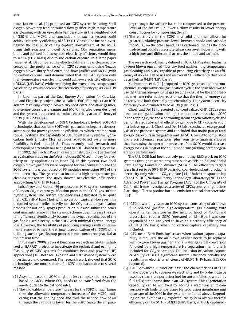
Table 4IGFC plant thermal performance summaries.
Pressurized SOFC, withanode exhaust recycled togasifier (baseline)
Pressurized SOFC, withanode exhaust recycled toSOFC
Near atmospheric SOFC,with anode exhaustrecycled to gasifier
Pressurized SOFC, withoutmethanation reactor beforesyngas expander
Coal energy input (GJ h−1) (HHV) 1397 1397 1397 1397SOFC operation pressure (bar) 10.1 10.1 1.1 10.1
Gross power output (major)SOFC electrical power (MW) 247.77 227.96 229.91 247.75Cathode exhaust expander (MW) 63.38 65.65 – 63.78Steam turbinea (MW) 2.57 3.09 1.43 2.80Syngas reactor/expander topping cycle (MW) 9.34 7.95 15.97 7.58Total gross power generated (MW) 323.30 304.99 247.55 322.13
Auxiliary power consumption (major)Coal milling and coal handling (MW) 0.60 0.60 0.60 0.60Coal pump, MW 1.60 1.60 1.60 1.60Coal drying air blower (MW) – – 4.91 –ASU air compressor (MW) 1.55 3.15 1.55 1.55ASU O2 compressor (MW) 0.55 1.62 0.55 0.55ASU auxiliary consumption (MW) 0.08 0.17 0.08 0.08SOFC air compressor/blower (MW) 66.91 65.99 11.07 66.92Recycled H2 compressor (MW) 8.24 5.03 18.87 8.22SelexolTM unit (MW) 0.98 1.40 1.02 0.98MDEA unit (MW) 0.62 0.59 0.60 0.62Gas cooling humidifier pump (MW) 0.09 0.09 0.09 0.09Recycled H2 humidifier pump (MW) 0.27 – 0.28 0.27Cooling tower fan (MW) 0.36 0.42 0.50 0.37Cooling tower pump (MW) 0.68 0.78 0.93 0.69Condensate recycle pump (MW) 0.29 0.30 0.37 0.29BFW feed pump (MW) 0.16 0.55 0.24 0.17Transformer losses (MW) 0.70 0.66 0.54 0.70Miscellaneous BOP and lighting (MW) 1.00 1.00 1.00 1.00Total internal power consumption and losses (MW) 84.68 83.95 44.87 84.70
Net electric power (MW) 238.62 221.04 202.69 237.435
rge cot
ee
5
w
coius
(
(
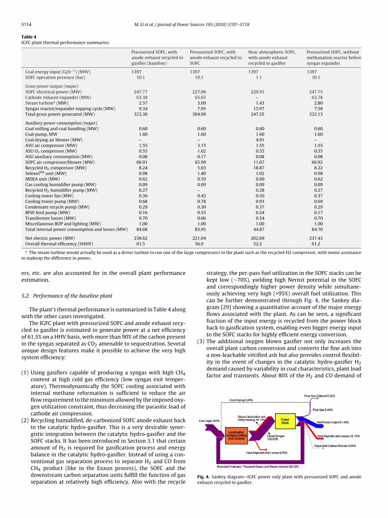
a non-leachable vitrified ash but also provides control flexibil-ity in the event of changes in the catalytic hydro-gasifier H2demand caused by variability in coal characteristics, plant loadfactor and transients. About 80% of the H2 and CO demand of
Overall thermal efficiency (%HHV) 61.5
a The steam turbine would actually be used as a driver turbine to run one of the lao makeup the difference in power.
rs, etc. are also accounted for in the overall plant performancestimation.
.2. Performance of the baseline plant
The plant’s thermal performance is summarized in Table 4 alongith the other cases investigated.
The IGFC plant with pressurized SOFC and anode exhaust recy-led to gasifier is estimated to generate power at a net efficiencyf 61.5% on a HHV basis, with more than 90% of the carbon presentn the syngas separated as CO2 amenable to sequestration. Severalnique design features make it possible to achieve the very highystem efficiency:
1) Using gasifiers capable of producing a syngas with high CH4content at high cold gas efficiency (low syngas exit temper-ature). Thermodynamically the SOFC cooling associated withinternal methane reformation is sufficient to reduce the airflow requirement to the minimum allowed by the imposed oxy-gen utilization constraint, thus decreasing the parasitic load ofcathode air compression.
2) Recycling humidified, de-carbonized SOFC anode exhaust backto the catalytic hydro-gasifier. This is a very desirable syner-gistic integration between the catalytic hydro-gasifier and theSOFC stacks. It has been introduced in Section 3.1 that certainamount of H2 is required for gasification process and energy
balance in the catalytic hydro-gasifier. Instead of using a con-ventional gas separation process to separate H2 and CO fromCH4 product (like in the Exxon process), the SOFC and thedownstream carbon separation units fulfill the function of gasseparation at relatively high efficiency. Also with the recycle6.9 52.2 61.2
mpressors in the plant such as the recycled H2 compressor, with motor assistance
strategy, the per-pass fuel utilization in the SOFC stacks can bekept low (∼70%), yielding high Nernst potential in the SOFCand correspondingly higher power density while simultane-ously achieving very high (>95%) overall fuel utilization. Thiscan be further demonstrated through Fig. 4, the Sankey dia-gram [29] showing a quantitative account of the major energyflows associated with the plant. As can be seen, a significantfraction of the input energy is recycled from the power blockback to gasification system, enabling even bigger energy inputto the SOFC stacks for highly efficient energy conversion.
(3) The additional oxygen blown gasifier not only increases theoverall plant carbon conversion and converts the fine ash into
Fig. 4. Sankey diagram—IGFC power only plant with pressurized SOFC and anodeexhaust recycled to gasifier.

r Sour
rldpsaTw
6
pctf
6S
aiS
M. LI et al. / Journal of Powe
the catalytic hydro-gasifier is met by the anode exhaust recyclestream while the remainder is supplied by the oxygen blowngasifier. Under scenarios where additional H2 is required by thecatalytic hydro-gasifier, feedstock input to this oxygen blowngasifier may be increased to increase its syngas production. Inaddition to its char feed (which is discharged from the catalytichydro-gasifier), coal may also be fed into the oxygen blown gasi-fier and its flow rate controlled to meet any variation in the H2(and CO) demand.
It should be noted that the overall system thermal efficiencieseported are based on the definition of system efficiency as estab-ished by the DOE for this study which does not include the penaltyue to CO2 compression and sequestration. For the baseline design,ressurizing the separated CO2 to the typical sequestration pres-ure of 151.7 bar (2200 psi) will consume about 11.6 MW of powernd cause the overall system efficiency to drop from 61.5% to 58.4%.he overall system efficiency of the other cases presented in thisork will also be affected in a similar manner.
. Alternative designs
In this section, some alternative designs and their thermalerformances are demonstrated and discussed. The IGFC systemonfigured with pressurized SOFC and anode exhaust gas recycledo gasifier will serve as a “baseline” case for comparison in theollowing discussions.
.1. IGFC with pressurized SOFC and anode exhaust recycled toOFC
The process scheme of this design is shown in Fig. 5. The char-cteristic of this design is that the de-carbonized anode exhausts not recycled back to the gasifier, but directly recycled to theOFC stacks and then mixed with the fresh clean syngas, resulting
Fig. 5. Block flow sketch—IGFC power only plant with pre
ces 195 (2010) 5707–5718 5715
in possibly a relatively simpler system configuration. Correspond-ingly the following modifications have to be made to accommodatethe change:
(1) Almost all the H2 (and CO) required by the catalytic hydro-gasifier is now supplied by the oxygen blown gasifier, resultingin higher O2 and coal input to the oxygen blown gasifier com-pared to the baseline case.
(2) The humidifier in the baseline design is not used anymore; thesteam requirement of the catalytic hydro-gasifier now has tobe met entirely by high pressure stream generator.
(3) Because the operating pressure of the SOFC stacks is lower thanthat of the gasifier, the de-carbonized anode exhaust recycledback to the SOFC stacks does not need to be compressed to ashigh pressure as in the baseline design. The anode exhaust iscooled while recovering its heat, trim cooled to ambient tem-perature against cooling water, pressurized to about 18 bar in acompressor and then fed to the MDEA unit. The de-carbonizedstream from the MDEA unit which is at pressure high enoughfor direct recycle is combined with fresh syngas and fed tothe SOFC stacks. This design eliminates the use of a relativelyinefficient ejector or a highly developmental high-temperaturecompressor.
(4) Small amount of de-carbonized anode exhaust is still com-pressed and fed back to the gasifier, but for the purpose ofinjecting the solid feedstock to the gasifier.
The system ended up with a thermal efficiency of 56.9%, whichis about 5 points lower than the baseline case. The per-pass fuel
utilization in the SOFC is set the same as used in the baseline case forconsistent comparison (which is also a good estimation to maintainreasonable cell Nernst potential). With the strategy of anode gasrecycling back to SOFC, the overall fuel utilization can be kept high(>95%).ssurizes SOFC and anode exhaust recycled to SOFC.

5 r Sour
stfri1
gcmfiiTats
6g
nnipfi
(
(
716 M. LI et al. / Journal of Powe
The overall auxiliary power consumptions of the two cases areimilar: in this design, the load of the air separation unit is morehan twice of the baseline design because much more O2 is requiredor the oxygen blown gasifier; but the work for compressing theecycled anode exhaust is also significantly smaller since the major-ty of the anode exhaust is only required to be compressed to about7 bar for use in SOFC rather than 75 bar for use in gasifier.
However, because more coal is now split to the oxygen blownasifier (for a given total coal input to the IGFC system), morehemical energy has to be utilized in the gasifier subsystem toaintain the higher operation temperature in oxygen blown gasi-
er. As a result, the overall efficiency of the gasification subsystemn this design is significantly lower than that of the baseline design.his results in smaller total energy input to the SOFC stacks, andlthough the two cases have similar overall fuel utilization aroundhe SOFC stacks, the power produced by fuel cells in this case isignificantly smaller than in the baseline case.
.2. IGFC with atmospheric SOFC and anode exhaust recycled toasifier
To demonstrate the effect of SOFC operation pressure, an alter-ative design where SOFC stack operation pressure was reduced toear atmospheric pressure was investigated. The process scheme
s shown in Fig. 6. The plant process scheme is similar to thereviously described baseline case. Major differences in the con-guration are identified as follows:
1) The expansion ratio of the turbine in the reactor/expander top-
ping cycle upstream of the SOFC system is significantly highersince the required anode inlet pressure is much lower for thiscase.2) Additional equipment is added between the anode exhaust gasleaving the SOFC stacks and the shift reactor in order to raise the
Fig. 6. Block flow sketch—IGFC power only plant with near at
ces 195 (2010) 5707–5718
gas pressure such that the shift reactor is operated at a pressurehigh enough to limit its size from becoming excessive. The gas iscooled to near ambient temperature after heat recovery whilecondensing out the water, compressed to a pressure of about20 bar, and humidified to re-introduce water vapor required bythe shift reaction prior to preheating and feeding it to the shiftreactor.
(3) The cathode air is supplied by a motor driven blower, whilethe combustor exhaust is fed directly to the heat recovery unitwhere the cathode inlet air is preheated and steam is generated.Because the combustor exhaust is at relatively low pressure, anadditional blower is needed to pressurize the portion of hotexhaust leaving the heat recovery unit for the coal drying oper-ation.
(4) A small fraction of the de-carbonized gas leaving the MDEACO2 separation unit is provided as fuel gas to the combustorto satisfy the heat requirement of the system.
The per pass fuel utilization in the SOFC is limited to about 68%in order to recycle the balance of H2 required by the catalytic hydro-gasifier. The overall fuel utilization is again much higher, at about93% due to the recycle.
This case with the near atmospheric SOFC has a net thermalefficiency that is about 9 percentage points lower than the baselinecase with the pressurized SOFC, which corresponds to an increaseof about 18% in heat rate. Both the gross power generation and theinternal power consumption of the pressurized system are higherthan those of the atmospheric system. The cathode air compressorin the pressurized case consumes a significant amount of power
while the turbine downstream of the SOFC stack produces a signif-icant amount of power and supplies majority of the power requiredby the compressor. The higher output of the reactor/expander top-ping cycle for the atmospheric system nearly compensates for thepower generated by the steam turbines in the pressurized system.mospheric SOFC and anode exhaust recycled to gasifier.

r Sour
Tda
osvatmpneSbie
6e
nttTstoaps
tistvt
7
aobicTssoatstnd
shmott
M. LI et al. / Journal of Powe
he lower net power output of the atmospheric system is mainlyue to the large compression load required for pressurizing thenode exhaust gas upstream of the shift reactor.
It should be pointed out that in this design the positive effectf high pressure on SOFC performance has not been fully demon-trated because a 0-D SOFC model is used and SOFC operatingoltages have been maintained constant at 0.8 V for both the neartmospheric pressure case and the pressurized case. In this workhe performance differences between the two cases are thus pri-
arily due to the differences in the arrangement of the balance oflant (BOP) equipment as required by the SOFCs with the two sig-ificantly different operating pressures. It has been demonstratedxperimentally that elevated pressure operation leads to enhancedOFC stack performance which is more than can be accounted fory Nernst effects alone [30,31] and future research work employ-
ng a dimensional SOFC model will further investigate the pressureffects.
.3. IGFC system without methanation reactor before syngasxpander
Finally the baseline system was modified to remove the metha-ation reactor and leave in a shift reactor in the reactor/expanderopping cycle to investigate the effect of this design. It was foundhat the system’s thermal efficiency was reduced slightly to 61.2%.his is because the shift reactor by itself also provides benefit (thehift reaction also being an exothermic reaction) by raising the inletemperature of the downstream expander to increase its powerutput [18] although not as much as the methanation reactor. Thedvantage of the reactor/expander topping cycle becomes moreronounced as the operating pressure of the SOFC is decreasedince the pressure ratio of the expander is increased.
However, the inclusion of a methanation reactor in the reac-or/expander topping cycle may still be preferred because it helpsn controlling the amount of CH4 in the syngas so that a relativelytable CH4 content in the syngas fed to SOFC stacks can be main-ained when the CH4 content in the gasifier effluent varies due toariability in coal characteristics as well as plant load factor andransients.
. Conclusions and recommendations
Coal-based power plants combining catalytic hydro-gasificationnd SOFC can be configured to achieve high efficiency approachingr exceeding 60% (HHV basis) while separating 90% of the car-on as CO2. The most promising configuration identified thus far
s the system with SOFC operated at elevated pressure and recy-ling de-carbonized, humidified anode exhaust back to the gasifier.he investigations into the various alternative designs have demon-trated that operating SOFC at elevated pressure provides the mostignificant efficiency benefit at a system level. The novel designf recycling de-carbonized anode exhaust gas back to the cat-lytic hydro-gasifier takes full advantage of the synergy betweenhe hydro-gasifier and the SOFC and is also essential to achievinguch high system efficiency. The methanation reactor in the reac-or/expander topping cycle in the elevated pressure IGFC case doesot provide a significant efficiency benefit but it may be a preferredesign for better control of the syngas quality.
Each of the IGFC plant configurations introduced above exhibitsignificantly higher efficiency than an IGCC plant [32]. In addition to
igh thermal efficiencies, IGFC plants have other advantages overore conventional coal-based power plants. The raw water usagef an IGFC plant is about half that of an IGCC when wet coolingowers are employed for plant heat rejection, the baseline sys-em presented in this work consuming only 0.7 m3 MW h−1 of raw
ces 195 (2010) 5707–5718 5717
water. Further, like most SOFC systems, the IGFC plants developedhere produce essentially no nitrogen oxide (NOx) emissions, sinceno high-temperature combustion of fuel with air takes place.
The catalytic hydro-gasifier and SOFC stacks are the two criticalbuilding blocks of such highly efficient IGFC plants. The remainderof the power plants may be configured with subsystems that havebeen commercially proven in similar services.
The desirable characteristics required of the catalytic hydro-gasifier, one of the two critical technologies required for such highefficiency IGFC plants are: (1) the ability to produce a syngas withhigh CH4 content (in excess of 35 mol% on a dry basis), (2) high coldgas efficiency (low syngas exit temperature), (3) the ability to pro-duce a tar- and oil-free syngas, (4) carbon conversion approaching90%. As introduced in Section 3.2, such catalytic hydro-gasificationtechnology was under development at Exxon in the 1970s and hasbeen attracting significant R&D interest more recently.
The required characteristics for the SOFC stack, the other criticaltechnology required for such high efficiency IGFC plants with CO2separation are: (1) operating pressure of approaching 10 bar, (2)separate anode and cathode exhausts, (3) SOFC internal reformingto minimize the excess air used for stack heat management (alsowithout excessive SOFC temperature gradients). Meeting theserequirements is not without challenges. The cathode and anodestreams must be maintained at similar pressures, as the planarSOFC itself is very thin and cannot support large pressure differ-entials. Transient pressure spikes on one side of the cell have thepotential to damage the SOFC. In the pressurized system presentedhere, the anode and cathode exhaust streams are kept separate(with the exception that the purge portion of the anode exhaust iscombusted with the cathode exhaust), likely presenting a systemcontrol challenge. SOFC operating pressure as high as 6 bar has beendemonstrated [30,31] but operating pressure around 10 bar has notbeen reported yet. Meanwhile, the thermal balance within the SOFCis complex and must be evaluated with a spatially resolved SOFCmodel in order to establish the true minimum air flow requiredsuch that maximum temperatures and temperature gradients arenot exceeded. Such an analysis is underway and the system will bemodified as necessary.
In the baseline case, the SOFC air compressor consumes morepower than that generated by the exhaust gas expander and if thetwo are hooked up on a common shaft, then a motor is requiredrather than a generator as the case for a typical natural gas-basedSOFC-GT hybrid. From a practical perspective, an easier designstrategy might be to have the two on separate shafts, with the com-pressor hooked up to a motor and the expander (turbine) hookedup to a generator. The separation will greatly support and enablebetter control and dynamic operation of the system. The abilityto independently manipulate and control these two componentsmay even be essential to off-design operating conditions such asstart-up and shut-down.
Attention should also be paid to the integration between SOFCand gasification subsystems through the recycle of anode exhaust.While this study has demonstrated the efficiency advantage of thisdesign, future research work is recommended to investigate thesystem dynamic behavior given the large flow rates of the recycleflow.
Acknowledgements
The authors wish to acknowledge the U.S. Department of Energy
and the National Energy Technology Laboratory under whosesponsorship the Advanced Power and Energy Program of the Uni-versity of California, Irvine conducted these studies (Contract No.RDS41817.3130105-036) with Research and Development Solu-tions, LLC as the Lead Contractor. This paper was prepared as an
5 r Sour
aetoatncmiSoo
R
[
[[[
[
[
[
[
[
[
[
[
[
[[[[
[
[Engineering and Technology Conference, Newport Beach, CA, 2009.
718 M. LI et al. / Journal of Powe
ccount of work sponsored by an agency of the United States Gov-rnment. Neither the United States Government nor any agencyhereof, nor any of their employees, makes any warranty, expressr implied, or assumes any legal liability or responsibility for theccuracy, completeness, or usefulness of any information, appara-us, product, or process disclosed, or represents that its use wouldot infringe privately owned rights. Reference herein to any specificommercial product, process, or service by trade name, trade-ark, manufacturer, or otherwise does not necessarily constitute or
mply its endorsement, recommendation, or favoring by the Unitedtates Government or any agency thereof. The views and opinionsf authors expressed herein do not necessarily state or reflect thosef the United States Government or any agency thereof.
eferences
[1] S.M. Klara, 10th Annual SECA Workshop, Pittsburgh, PA, 2009.[2] D. Jansen, A.B.J. Oudhuis, H.M. van Veen, Energy Conversion and Management
33 (1992) 365–372.[3] D. Jansen, P.C. van der Laag, A.B.J. Oudhuis, J.S. Ribberink, Journal of Power
Sources 49 (1994) 151–165.[4] M. Maruyama, S. Takahashi, J. Iritani, H. Miki, 2000 Gasification Technologies
Conference, San Francisco, CA, 2000.[5] A.F. Massardo, F. Lubelli, Journal of Engineering for Gas Turbines and Power 122
(2000) 27–35.[6] A.F. Massardo, L. Magistri, Journal of Engineering for Gas Turbines and Power
125 (2003) 67–74.[7] Y. Yi, A.D. Rao, J. Brouwer, G.S. Samuelsen, Journal of Power Sources 132 (2004)
77–85.
[8] R.A. Roberts, J. Brouwer, Journal of Fuel Cell Science and Technology 3 (2006)18–25.[9] K.V. Lobachyov, H.J. Richter, Energy Conversion and Management 38 (1997)
1693–1699.10] T. Kivisaari, P. Björnbom, C. Sylwan, B. Jacquinot, D. Jansen, A. de Groot, Chemical
Engineering Journal 100 (2004) 167–180.
[[[[
ces 195 (2010) 5707–5718
11] P. Kuchonthara, S. Bhattacharya, A. Tsutsumi, Fuel 84 (2005) 1019–1021.12] S. Ghosh, S. De, Energy 31 (2006) 345–363.13] S. Ghosh, S. De, International Journal of Energy Research 30 (2006) 647–
658.14] L.A. Ruth, Vision 21: Ultra-Clean Energy Plants for the 21st Century 2000 Gasi-
fication Technologies Conference, San Francisco, CA, 2000.15] A.D. Rao, A. Verma, G.S. Samuelsen, ASME Turbo Expo 2005: Power for Land
Sea and Air, Reno-Tahoe, NV, 2005.16] A. Verma, A.D. Rao, G.S. Samuelsen, Journal of Power Sources 158 (2006)
417–427.17] K. Gerdes, E. Grol, D. Kearins, R. Newby, Integrated Gasification Fuel Cell Perfor-
mance and Cost Assessment, DOE/NETL-2009/1361, U.S. Department of Energy,Morgantown, WV, 2009.
18] A.D. Rao, Reactor expander topping cycle, U.S. Patent No. 4,999,993 (1991March).
19] K.P. Recknagle, B.J. Koeppel, X. Sun, M.A. Khaleel, S.T. Yokuda, P. Singh, ECSTransactions 5 (2007) 473–478.
20] T. Kalina, N.C. Nahas, Exxon catalytic coal gasification process predevelopmentprogram final project report, Exxon Research and Engineering Company, Bay-ton, TX, 1978.
21] N.C. Nahas, J.E. Gallagher, 13th Intersociety Energy Conversion EngineeringConference, San Diego, CA, 1978.
22] R. Hobbs, Development of a Hydrogasification Process for Co-production ofSubstitute Natural Gas (SNG) and Electric Power from Western Coals-Phase ITopical Report, Arizona Public Service, Phoenix, AZ, 2007.
23] W.A. Surdoval, 10th Annual SECA Workshop, Pittsburgh, PA, 2009.24] R. Kerr, 10th Annual SECA Workshop, Pittsburgh, PA, 2009.25] B. Borglm, 10th Annual SECA Workshop, Pittsburgh, PA, 2009.26] Aspen Plus, Aspen Plus User Guide, Aspen Technology Inc., Cambridge, MA,
2003.27] T. Kivisaari, P. Björnbom, C. Sylwan, Journal of Power Sources 104 (2002)
115–124.28] M. Li, J. Brouwer, J.D. Powers, G.S. Samuelsen, 7th International Fuel Cell Science,
29] M. Schmidt, Journal of Industrial Ecology 12 (2008) 82–94.30] N. Minh, 7th Annual SECA Workshop, Philadelphia, PA, 2006.31] T. Ohrn, 10th Annual SECA Workshop, Pittsburgh, PA, 2009.32] M.C. Woods, et al. (Eds.), Cost and Performance Baseline for Fossil Energy Plants,
DOE/NETL-2007/1281, U.S. Department of Energy, Morgantown, WV, 2007.