Design of Fuzzy Logic Tuned PID Controller for Electric ...
9
J Electr Eng Technol.2018; 13(1): 451-459 http://doi.org/10.5370/JEET.2018.13.1.451 451 Copyright ⓒ The Korean Institute of Electrical Engineers This is an Open-Access article distributed under the terms of the Creative Commons Attribution Non-Commercial License (http://creativecommons.org/ licenses/by-nc/3.0/) which permits unrestricted non-commercial use, distribution, and reproduction in any medium, provided the original work is properly cited. Design of Fuzzy Logic Tuned PID Controller for Electric Vehicle based on IPMSM Using Flux-weakening Ali Rohan † , Furqan Asghar* and Sung Ho Kim* Abstract – This work presents an approach for modeling of electric vehicle considering the vehicle dynamics, drive train, rotational wheel and load dynamics. The system is composed of IPMSM (Interior Permanent Magnet Synchronous Motor) coupled with the wheels through a drive train. Generally, IPMSM is controlled by ordinary PID controllers. Performance of the ordinary PID controller is not satisfactory owing to the difficulties of optimal gain selections. To overcome this problem, a new type of fuzzy logic gain tuner for PID controllers of IPMSM is required. Therefore, in this paper fuzzy logic based gain tuning method for PID controller is proposed and compared with some previous control techniques for the better performance of electric vehicle with an optimal balance of acceleration, speed, travelling range, improved controller quality and response. The model was developed in MATLAB/Simulink, simulations were carried out and results were observed. The simulation results have proved that the proposed control system works well to remove the transient oscillations and assure better system response in all conditions. Keywords: Electric vehicle, Fuzzy logic, IPMSM, PID, Flux-weakening, Vector control 1. Introduction Electric vehicle system basically comprises of an electric motor, power converters, controller, power source and drive train. Power can be supplied to the system by any stored electrical energy device such as battery, fuel cell, ultra- capacitors. Generally, electric vehicle use a battery system as its main energy source [1, 2]. As the electric vehicles are driven by a stored electrical energy source, the drive range is always limited depending upon the efficiency of the system and capacity of the energy source. One way to improve the efficiency of the system is by improving the control system of the electric vehicle. Therefore, an effective control system is required for the robust and energy efficient operation of the electric vehicle. For this, an adaptive fuzzy technique is proposed in this work to control the system operation efficiently. Using fuzzy logic allows to deal with the uncertainties or unknown variations in plant parameters in better way to increase the system robustness [3, 4]. This control method is more stable and allows various design objectives. Fuzzy controllers unlike PI controllers do not require the accurate mathematical model of the process, rather it needs the experience and knowledge about the controlled process to construct the rule base [5, 6]. Previously used control techniques involve controllers like PID, Fuzzy logic, neuro Fuzzy. In recent years, various research methods based on advanced control strategies in electric vehicles has been introduced. In [7, 8], authors used intelligent fuzzy control to increase the efficiency of the system while dealing with the complex operation modes. In [9, 10] different control strategies based on PI methods are used to control the electric vehicle system by performing mathematical modeling of electric motor and electric vehicle dynamics. These controllers are simple and do not perform well for control systems with changing parameters and require frequent on-line tuning. Tuning is done by manual or hit and trial methods to choose proper gains. The initial gain selection is an important factor in the performance of any controller, careful choice of these gains can lead towards better system response. Previously this initial gain selection is made upon the knowledge about the control system behavior but in case of a control system with changing parameters these gains should be tuned according to the changing system parameters. Nowadays fuzzy logic is used to control such control systems by determining the controller gains on-line, based on the error signal and their time derivative. These fuzzy logic controllers may be considered as nonlinear PID controllers. The fuzzy logic works well under the changing system parameters but in order to make the controller much precise the static initial gain must be selected properly to avoid the sub-optimal response. For this, another fuzzy logic is used to carefully tune the static initial gains working in parallel with the fuzzy tuned PID controller. This additional fuzzy logic controller provides the compensation in the gain tuning with ability to respond under changing system parameters and making the system † Corresponding Author: School of Electronics and Information Engineering, Kunsan National University, Korea. ([email protected]) * Dept. of Electrical and Electronic Engineering, Kunsan National University, Korea. ({furqan, shkim}@kunsan.ac.kr) Received: April 6, 2017; Accepted: August 14, 2017 ISSN(Print) 1975-0102 ISSN(Online) 2093-7423
Transcript of Design of Fuzzy Logic Tuned PID Controller for Electric ...
J Electr Eng Technol.2018; 13(1): 451-459http://doi.org/10.5370/JEET.2018.13.1.451
451Copyright ⓒ The Korean Institute of Electrical Engineers
This is an Open-Access article distributed under the terms of the Creative Commons Attribution Non-Commercial License (http://creativecommons.org/licenses/by-nc/3.0/) which permits unrestricted non-commercial use, distribution, and reproduction in any medium, provided the original work is properly cited.
Design of Fuzzy Logic Tuned PID Controller for Electric Vehicle based on IPMSM Using Flux-weakening
Ali Rohan†, Furqan Asghar* and Sung Ho Kim*
Abstract – This work presents an approach for modeling of electric vehicle considering the vehicle dynamics, drive train, rotational wheel and load dynamics. The system is composed of IPMSM (Interior Permanent Magnet Synchronous Motor) coupled with the wheels through a drive train. Generally, IPMSM is controlled by ordinary PID controllers. Performance of the ordinary PID controller is not satisfactory owing to the difficulties of optimal gain selections. To overcome this problem, a new type of fuzzy logic gain tuner for PID controllers of IPMSM is required. Therefore, in this paper fuzzy logic based gain tuning method for PID controller is proposed and compared with some previous control techniques for the better performance of electric vehicle with an optimal balance of acceleration, speed, travelling range, improved controller quality and response. The model was developed in MATLAB/Simulink, simulations were carried out and results were observed. The simulation results have proved that the proposed control system works well to remove the transient oscillations and assure better system response in all conditions.
Keywords: Electric vehicle, Fuzzy logic, IPMSM, PID, Flux-weakening, Vector control
1. Introduction
Electric vehicle system basically comprises of an electric motor, power converters, controller, power source and drive train.
Power can be supplied to the system by any stored electrical energy device such as battery, fuel cell, ultra-capacitors. Generally, electric vehicle use a battery system as its main energy source [1, 2]. As the electric vehicles are driven by a stored electrical energy source, the drive range is always limited depending upon the efficiency of the system and capacity of the energy source. One way to improve the efficiency of the system is by improving the control system of the electric vehicle. Therefore, an effective control system is required for the robust and energy efficient operation of the electric vehicle. For this, an adaptive fuzzy technique is proposed in this work to control the system operation efficiently. Using fuzzy logic allows to deal with the uncertainties or unknown variations in plant parameters in better way to increase the system robustness [3, 4]. This control method is more stable and allows various design objectives. Fuzzy controllers unlike PI controllers do not require the accurate mathematical model of the process, rather it needs the experience and knowledge about the controlled process to construct the rule base [5, 6].
Previously used control techniques involve controllers
like PID, Fuzzy logic, neuro Fuzzy. In recent years, various research methods based on advanced control strategies in electric vehicles has been introduced. In [7, 8], authors used intelligent fuzzy control to increase the efficiency of the system while dealing with the complex operation modes. In [9, 10] different control strategies based on PI methods are used to control the electric vehicle system by performing mathematical modeling of electric motor and electric vehicle dynamics. These controllers are simple and do not perform well for control systems with changing parameters and require frequent on-line tuning. Tuning is done by manual or hit and trial methods to choose proper gains. The initial gain selection is an important factor in the performance of any controller, careful choice of these gains can lead towards better system response. Previously this initial gain selection is made upon the knowledge about the control system behavior but in case of a control system with changing parameters these gains should be tuned according to the changing system parameters. Nowadays fuzzy logic is used to control such control systems by determining the controller gains on-line, based on the error signal and their time derivative. These fuzzy logic controllers may be considered as nonlinear PID controllers. The fuzzy logic works well under the changing system parameters but in order to make the controller much precise the static initial gain must be selected properly to avoid the sub-optimal response. For this, another fuzzy logic is used to carefully tune the static initial gains working in parallel with the fuzzy tuned PID controller. This additional fuzzy logic controller provides the compensation in the gain tuning with ability to respond under changing system parameters and making the system
† Corresponding Author: School of Electronics and Information Engineering, Kunsan National University, Korea.([email protected])
* Dept. of Electrical and Electronic Engineering, Kunsan National University, Korea. ({furqan, shkim}@kunsan.ac.kr)
Received: April 6, 2017; Accepted: August 14, 2017
ISSN(Print) 1975-0102ISSN(Online) 2093-7423

Design of Fuzzy Logic Tuned PID Controller for Electric Vehicle based on IPMSM Using Flux-weakening
452 │ J Electr Eng Technol.2018; 13(1): 451-459
much reliable in the close loop operation. A rule based scheme for gain scheduling is proposed. Proposed system is tested under different scenarios using MATLAB/Simulink. This paper is divided into following sections: Section 2 describes the modelling of electric vehicle comprising of vehicle dynamics, transmission unit and electric motor. Section 3 consists of the design and implementation of control techniques. Section 4 contains the simulation studies and section 5 outlines the conclusion.
2. Modeling of Electric Vehicle
Fig. 1. shows the Components of an electric vehicle system. Different types of electric motors can be used such as DC motor, BLDC (Brush Less DC motor), IM (Inductionmotor), PMSM (Permanent Magnet Synchronous Machine) and IPMSM (Interior Permanent Magnet Synchronous Machine). In this paper, IPMSM is used as electric motor. Main objective behind selection of IPMSM is due to the simple and efficient control designs with high speed operation and reliable structure. Buck-boost power converteris used for operational control and power conversion as required by IPMSM. Flux-weakening and MTPA (MaximumTorque Per Ampere) control technique is used to control the operation of the IPMSM. Two loops of operation are proposed: the outer loop is the speed control loop which generates the nominal torque and flux references and the inner loop is the current control loop comprising of flux weakening and MTPA operation of the controller.
In order to model an electric vehicle system, EV dynamics, power source, control and drive of IPMSM, transmission unit and rotational wheels are considered. EV dynamics are composed on all the forces acting on the vehicle. Transmission unit is modeled by high speed and low speed shaft with a gear reducer. Rotational wheels are attached as load with the transmission unit. Battery is used as power source whereas IGBT inverter is used to drive and control the operation of the IPMSM.
2.1 Electric vehicle dynamics
Generally the modelling of an electric vehicle dynamics depends on the balance among the forces acting on a running vehicle.
Fig. 1 Block diagram of an electric vehicle
These forces are: 1) Force due to gravity, gravitational force. 2) Force required to cover inclined surface hindrance, hill climbing force. 3) Force between the tires and the road, rolling resistance force. 4) Force due to aerodynamic, aerodynamic drag force. Considering all these factors, a vehicle dynamic model that governs the kinetic of thewheels and vehicle can be written as [11].
�� = ���
��+ �� + �� + ��(1)
Where �� is the total traction force, �� is the gravitational force, �� is the aerodynamic drag force, �� is the rolling resistance force, � is the mass of the vehicle and � is the linear velocity.
�� = �� sin� (2)
�� =1
2�����(3)
�� = ���� cos�(4)
Where � is the mass of the vehicle, � is the gravitational acceleration, � is the air density, � is the front area of the vehicle, � is the drag coefficient, � is the linear velocity, �� is the rolling resistance coefficient and �is the inclination angle. Therefore, simplified version of Eq. (1)-(4) can be written as:
�� = ���
��+ �� sin� +
1
2����� + �� cos � (5)
Eq. (5) summarizes the dynamics for an electric vehicle system.
2.2 Transmission unit
Transmission system is modelled using a gear reducer with a high speed shaft and low speed [12]. The relationship between force (��), radius(�), reduction ratio (�) and torque produced by driving motor �� is given as:
�� =�.���(6)
IPMSM is coupled to the high speed shaft and rotational wheels with the low speed shaft. Whole system is modelled
Fig. 2 Transmission system

Ali Rohan, Furqan Asghar and Sung Ho Kim
http://www.jeet.or.kr │ 453
using the MATLAB/ Simulink. Fig. 2. shows the basic schematic of the transmission unit.
The reduction device dynamics are given as:
������
��= �� −
����� ∗ �
(7)
Where, ��� is the inertia of the reduction device, ���
��is
the acceleration of the high speed side, �� is the torque transmitted by the high speed shaft to the input of the reduction device, �� is the torque transmitted by the low speed shaft from the output of the reduction device, ��� is the efficiency of the reduction device and �is the reduction ratio.
The output speed ���� (speed of the low side) and ����(speed of the high side) is:
���� =�����(8)
The rotational load wheels coupled on the low speed shaft are given as:
����
��= �� −��(9)
2.3 IPMSM control
For IPMSM, generally two types of control techniques are used. 1) Direct torque control (DTC) 2) Vector control. In DTC, the switching speed is low and motor has low inductance. Therefore, significant current and torque ripples are generated at low speed causing the limitation in the speed regulation of the system, whereas in vector control, these sort of problems can be handled [13]. Therefore, the vector control is used in this work to control the operation of IPMSM.
Two loops of operation are used: 1) inner current control loop 2) outer speed control loop. Fig. 3. shows the basic block diagram of the control system. ���� , �� are the speed reference and speed of the low speed shaft respectively. Three types of speed controller are discussed and compared.
Fig. 3 Control system block diagram
3. Various Control Strategies
3.1 Type 1: PI controller
Simple PI controller is used to control the system responseas shown in Fig. 4. Speed controller takes the speed reference and the actual speed of the vehicle as an input and generate the torque and flux references as an output which is further given as an input to the inner current control loop. The inner current control loop regulates the current of the motor using the MTPA and flux-weakening operation.
Eq. (10) gives the relation between the torque and dq-axis current. Using torque reference, �� ∗ , �� ∗ are generated to regulate the current and PWM pulses to operate the inverter.
�� =3
2���λ��� + ��� − ��������(10)
3.2 Type 2: Fuzzy tuned PI controller
In this type of controller, Fuzzy logic is used to generate
Fig. 4. Block diagram of PI controller
Fig. 5. Block diagram of fuzzy PI controller

Design of Fuzzy Logic Tuned PID Controller for Electric Vehicle based on IPMSM Using Flux-weakening
454 │ J Electr Eng Technol.2018; 13(1): 451-459
(a)
(b)
Fig. 6. Membership functions: (a) Input membership functions, error �(�) and change of error �(�); (b) Output membership functions ��, ��.
�� and �� gains, providing compensation for the parallel PI controller gains. Fig. 5. shows the type 2 speed controller.
As fuzzy system accepts the linguistic variables, so these variables need to be changed by fuzzification followed by the max-min method to set the rules of the controller. Control system cannot directly respond to the fuzzy control output generated by the fuzzy algorithm. Therefore defuzzification is used to change back the generated output.
Fuzzy logic consists of two input variables: �(�) and �(�) and two output variables: �� and �� . The membership functions are shown in Fig. 6.
Rule base used for �� and �� is given in Table 1 and 2 respectively.
Table 1. Rule base for�� (Proportional gain).
∆�(�)�(�)� NB NM NS ZE PS PM PB
NB PB PB PM PM PS ZE ZE
NM PB PB PM PS PS ZE NS
NS PM PM PM PS ZE NS NS
ZE PM PM PS ZE NS NM NM
PS PS PS ZE NS NS NM NM
PM PS ZE NS NM NM NM NB
PB ZE ZE NM NM NM NB NB
Table 2. Rule Base for�� (Integral gain).
∆�(�)�(�)� NB NM NS ZE PS PM PB
NB NB NB NM NM NS ZE ZE
NM NB NB NM NS NS ZE ZE
NS NB NM NS NS ZE PS PS
ZE NM NM NS ZE PS PM PB
PS NM NS ZE PS PS PM PB
PM ZE ZE PS PS PM PB PB
PB ZE ZE PS PM PM PB PB
Fig. 7. Type 3 speed controller: adaptive Fuzzy PID controller
3.3 Type 3: Proposed fuzzy logic based static gain tuning for fuzzy tuned PID controller
In this type of controller, adaptive fuzzy logic technique is used to control the system. Fuzzy logic works as gain tuner for PID controller by calculating the �� , �� , ��gains. Comparing with the previous types, the proposed controller works on the base of parameter estimation under changing system conditions and do not require any on-line tuning methods. Fig. 7. shows the proposed control scheme.
The Transfer function of PID controller is given as:
�(�) = �� +��
�� + ���(11)
The discrete-time equivalent expression for PID control is given as:
�(�) = ���(�) + ������(�)
�
���
+����Δe(k)(12)
Where �� , �� and �� are proportional, integral and
derivative gains. Also, /i p iT K K= and /d d pT K K= .
�� and �� are the integral and derivative time constants, respectively. �� is the sampling time of the controller.�� and �� are normalized as:
��� =
�� − ��.�����.��� −��.���
(13)
��� =
�� − ��.�����.��� − ��.���
(14)
Therefore, integral time constant w.r.t derivative time constant is:

Ali Rohan, Furqan Asghar and Sung Ho Kim
http://www.jeet.or.kr │ 455
�� = ��� (15)
Whereas, Integral gain can be calculated as:
�����
(���)=
���
(���)(16)
Form Eqs. (13), (14) and (15):
�� = ���.��� −��.������� + ��.���(17)
�� = (��.��� − ��.���)��� +��.��� (18)
(a)
(b)
(c)
Fig. 8. Membership functions: (a) Input membership functions error �(�) and change of error �(�); (b) Output membership functions �� and ��; (c) Output membership functions for�
Table 3. Rule base used for�� (Proportional gain)
∆�(�)�(�)� NB NM NS ZE PS PM PB
NB B B B B B B B
NM S B B B B B S
NS S S B B B S S
ZE S S S B S S S
PS S S B B B S S
PM S B B B B B S
PB B B B B B B B
Table 4. Rule base used for �� (Derivative gain).
∆�(�)�(�)� NB NM NS ZE PS PM PB
NB S S S S S S S
NM B B S S S B B
NS B B B S B B B
ZE B B B B B B B
PS B B B S B B B
PM B B S S S B B
PB S S S S S S S
Table 5. Rule base used for �.
∆�(�)�(�)� NB NM NS ZE PS PM PB
NB 2 2 2 2 2 2 2
NM 3 3 2 2 2 3 3
NS 4 3 3 2 3 3 4
ZE 5 4 3 3 3 4 5
PS 4 3 3 2 3 3 4
PM 3 3 2 2 2 3 3
PB 2 2 2 2 2 2 2
Two input variables �(�) and �(�) , three output variables �� , �� and � are used. � is used as a fuzzy number which has a singleton membership function. The membership functions are shown in the Fig. 8.
In Fig. 7. Fuzzy logic controller 1 uses the same rule base as in type 2 fuzzy PI controller, whereas the Fuzzy logic controller 2 uses the rule base shown in Table.3, 4, 5.
4. Simulation Studies
Proposed system is designed in MATLAB/Simulink and simulation studies are carried out to verify the system feasibility. Designed system is tested under different road and command speed scenarios. Simulink model of the system is shown in Fig. 9.
4.1 Implementation of controllers and transmission unit
Simulink representation of the type 1, type 2, type 3 speed controller and current or vector controller is shown in the Fig. 10.
Transmission system used in the system with high speed and low speed shafts modelled in Simulink and shown in Fig. 11.
4.2 Simulation results
To test the control systems; type1, type 2 and type 3, simulation studies are carried out with some specific speed profiles. Fig. 12. shows the obtained results. It can be observed from the speed and torque profile and the output mechanical power that the proposed controller have a better response and works well under changing load

Design of Fuzzy Logic Tuned PID Controller for Electric Vehicle based on IPMSM Using Flux-weakening
456 │ J Electr Eng Technol.2018; 13(1): 451-459
parameters. The proposed controller causes the system to work efficiently and less amount of output mechanical power is consumed.
Fig. 13. shows the �� , �� current and �� , �� voltages response under proposed control system. At time t= 1.6 sec, t=4.5 sec, t=10 sec flux weakening is performed to limit the back electromotive force of the motor and �� current component is increased negatively. Three phase current of the motor is shown in Fig. 14.
Fig. 15. shows the output of the type 3 proposed
controller. It can be observed that ��, �� , �� gains and alpha value changes as per the system changing parameters.
The performance of the proposed control system is analyzed using some parameters like Sum of Square Error given as:
���� = ���(�)��
���
(19)
Fig. 9. Simulink model of proposed system
(a)
(b)
(c)
(d)
Fig. 10. Simulink representation of controllers: (a) Type 1; (b) Type 2; (c) Type 3; (d) Vector control or current controller

Ali Rohan, Furqan Asghar and Sung Ho Kim
http://www.jeet.or.kr │ 457
Fig. 11. Simulink representation of the transmission system
Performance index is calculated for all the three types of control system, values obtained are 3.1977�13 for type 1 controller, 3.1974�13 for type 2 controller and 3.1965�13 for type 3: proposed controller. The values shows that the proposed system performance is much better than the other types of controller
To systematically test the performance of the type 3 controller, New European Driving Cycle (NEDC) is used. The NEDC is a driving cycle consists of four repeated ECE-15 driving cycle and an Extra-Urban driving cycle. The test result is shown in the Fig. 16. The maximum speed is scaled as 114 km/h or 31.6 m/s. These results
Fig. 12. Output response of type 1, type 2, type 3 controller
Fig. 13. ��, �� and �� , �� response for proposed controller
Fig. 14. Three phase current of IPMSM

Design of Fuzzy Logic Tuned PID Controller for Electric Vehicle based on IPMSM Using Flux-weakening
458 │ J Electr Eng Technol.2018; 13(1): 451-459
Table 6. Parameters
Parameters Value
Electric Vehicle (EV)
�: EV mass 800��
�: Frontal Area 1.8��
�: Air density 1.25��/��
�:Aaerodynamic coefficient 0.3
��: Rolling resistance coefficient 0.015
�: Tire radius 0.25�
�: Gravitational acceleration 9.8�/��
�: Gear ratio 10
�: Inertia 50����
�: Friction coefficient 0.01
�: Inclination angle 0�
���: Efficiency 95%
Motor
��: Rated Power 2.5��
��: Rated Torque 50��
�: Rated angular speed 3600���
��:Number of poles 2
��, ��: dq-axis inductance 8.5����
��: Flux Linkage 0.175
�: Current 25�
Battery
Battery capacity 15�ℎ
���: Dc voltage 400�
show that the proposed type 3 controller tracks the speed profile efficiently and better than the type 1 and type 2 controllers.
The parameters used are shown in Table 6.
5. Conclusion
To improve the performance, a new approach is used to design and model the electric vehicle system considering all the aspects such as drive train, wheels and torque load characteristics. Fuzzy logic based efficient control system is proposed for IPMSM with flux-weakening and maximumtorque per ampere operation. Different simulations are carried out to test the system feasibility using MATLAB/Simulink. The results show that the proposed technique works better in all conditions and give fast and accurate torque response.
Conflict of Interest
The author’s declare that there is no conflict of interest regarding the publication of this paper.
Fig. 15. Controller output for��, ��, �� gains and alpha
Fig. 16. Output response for NEDC
Ali Rohan, Furqan Asghar and Sung Ho Kim
http://www.jeet.or.kr │ 459
References
[1] Bambang Sri Kaloko, Soebagio, Mauridhi Hery Purnomo, Design and Development of Small Electric Vehicle using MATLAB/Simulink, international Journal of Computer Applications (0975 – 8887) Volume 24– No.6, June 2011.
[2] Dhameja, S., Electric Vehicle Battery Systems, Newnes, US. 2002.
[3] Cao, S.-G., Rees, N. & Feng, G. [1999]. Analysis and design of fuzzy control systems using dynamic fuzzy-state space models, Fuzzy Systems, IEEE Trans-actions on 7(2): 192-200.
[4] Chen, C.-L. & Chang, M.-H. [1998]. optimal design of fuzzy sliding-mode control: A comparative study,Fuzzy Sets and Systems 93(1): 37-48.
[5] Kovacic, Z. & Bogdan, S. [2006]. Fuzzy Controller Design: Theory and Applications, CRC Press.
[6] Yamakawa, T. [1993]. A fuzzy inference engine in nonlinear analog mode and its application to a fuzzy logic control, Neural Networks, IEEE Transactions on 4(3): 496-522.
[7] Husain, I., 2003, Electric and Hybrid Vehicles Design Fundamentals, Pertama, CRC Press, Farhan A. Salem, Mechatronics design of small electric Vehicles; Research and education, International Journal of Mechanical & Mechatronics Engineering IJMME-IJENS Vol:13, No:01,2013.
[8] Poorani, S., Kumar, K.U., Renganarayanan S. (2003). Intelligent controller design for electric vehicle. Proc. 57th IEEE Semiannual Vehicular Technology Conf., pp. 2447-2450, Jeju, Korea, Apr. 2003.
[9] Khatun, P., Bingham, C.M., Schofield, N., Mellor, P.H. (2003). Application of fuzzy control algorithms for electric vehicle antilock braking/traction control systems. IEEE Trans. Vehicular Tech., Vol. 52 (5), 2003, pp. 1356-1364.
[10] Farhan A. Salem, Ahmad A. Mahfouz, Modeling and controller design for electric motor, using different control strategies and verification using MATLAB/Simulink I.J. Intelligent Systems and Applications, submitted and accepted to I.J. Intelligent Systems and Applications, 2013.
[11] wry, J.(2003). Electric Vehicle Technology Explained. pp. 183 – 195, John Wiley & Sons, Ltd., ISBN 0-470-85163-5, UK
[12] Profumo, F., Madlena, M., Griva. G. (1996). State variables controller design for vibrations suppression in electric vehicles. Proc. 27th Annual IEEE Power Electronics Specialists Conference, pp. 1940-1947, 1996.
[13] Liu, Q., Zhong, Y., Zhou Z. (2004). Research of drive control system in electric vehicle based on DSP. Proc. 7th Int. Conf. Signal Processing, pp. 539-542, Beijing, China, Aug. 2004.
[14] Koutsogiannis, Z., Adamidis, G. & Fyntanakis, A.
[2007]. Direct torque control using space vector modulation and dynamic performance of the drive, via a fuzzy logic controller for speed regulation, Power Electronics and Applications, 2007 EuropeanConference on pp. 1-10.
[15] Krause, P. C., Wasynczuk, O. & Sudhoff, S. D. [2002]. Analysis of Electric Machinery and Drive Systems, IEEE Press.
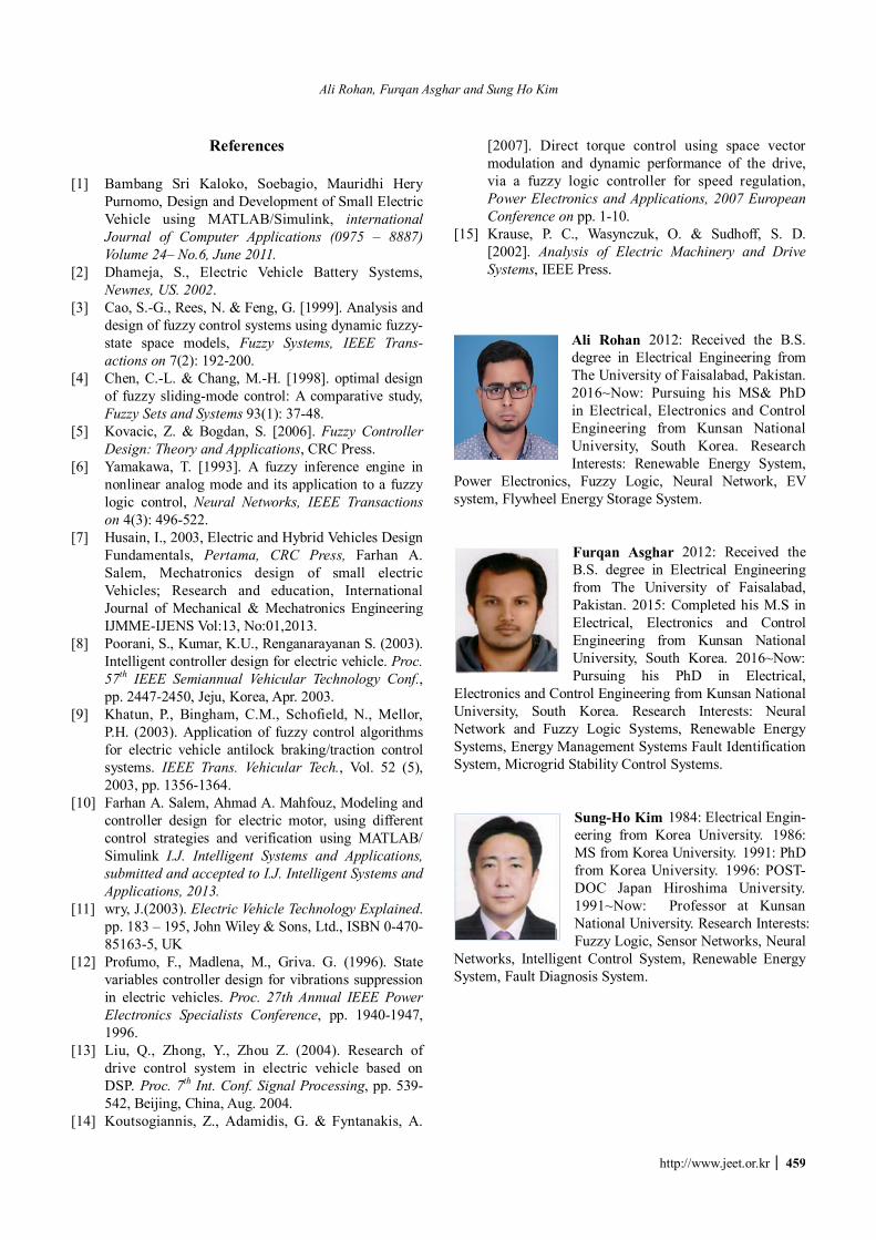
Ali Rohan 2012: Received the B.S. degree in Electrical Engineering from The University of Faisalabad, Pakistan.2016~Now: Pursuing his MS& PhD in Electrical, Electronics and Control Engineering from Kunsan National University, South Korea. Research Interests: Renewable Energy System,
Power Electronics, Fuzzy Logic, Neural Network, EV system, Flywheel Energy Storage System.
Furqan Asghar 2012: Received the B.S. degree in Electrical Engineering from The University of Faisalabad, Pakistan. 2015: Completed his M.S in Electrical, Electronics and Control Engineering from Kunsan National University, South Korea. 2016~Now: Pursuing his PhD in Electrical,
Electronics and Control Engineering from Kunsan National University, South Korea. Research Interests: Neural Network and Fuzzy Logic Systems, Renewable Energy Systems, Energy Management Systems Fault Identification System, Microgrid Stability Control Systems.
Sung-Ho Kim 1984: Electrical Engin-eering from Korea University. 1986: MS from Korea University. 1991: PhD from Korea University. 1996: POST-DOC Japan Hiroshima University.1991~Now: Professor at Kunsan National University. Research Interests: Fuzzy Logic, Sensor Networks, Neural
Networks, Intelligent Control System, Renewable Energy System, Fault Diagnosis System.