
DESIGN OF FRP STRUCTURES IN SEISMIC ZONE · Design of FRP structures in seismic zone Manual by Top...
35
DESIGN OF FRP STRUCTURES IN SEISMIC ZONE Giosue' Boscato, Carlo Casalegno, Salvatore Russo
Transcript of DESIGN OF FRP STRUCTURES IN SEISMIC ZONE · Design of FRP structures in seismic zone Manual by Top...
DESIGN OF FRP STRUCTURES IN SEISMIC ZONE
Giosue' Boscato, Carlo Casalegno, Salvatore Russo
Design of FRP structures in seismic zone
Manual by Top Glass S.p.A. and IUAV University of Venice 1
DESIGN OF FRP STRUCTURES IN SEISMIC ZONE
Giosuè Boscato(**)
Carlo Casalegno(*)
Salvatore Russo(*)
(*) IUAV University of Venice, Department of Design and Planning in Complex Environments,
Dorsoduro 2206, 30123, Venice, Italy, phone +39 041 2571290 fax +39 041 5312988;
(**) IUAV University of Venice, Laboratory of Strength of Materials (LabSCo), Via Torino 153/A -
30173 Mestre, Venice, Italy, phone +39 041 2571481 fax +39 041 5312988; [email protected]
Design of FRP structures in seismic zone
Manual by Top Glass S.p.A. and IUAV University of Venice 2
Preface
The use of FRP (Fibre Reinforced Polymer) material in the structural engineering field is by now
current practice and supported by theoretical studies as well as many applications and constructions.
FRP material is widely accepted in the strengthening of existing structures (made by reinforced
concrete, steel, wood and masonry) but not yet commonly used for new buildings even if some
recent all-FRP constructions, in particular built with FRP members made by pultrusion process, are
very promising.
The study of the structural behaviour of pultruded FRP members, especially in the case of static
loads, has been widely developed. Instead, for what concerns the dynamic response, very few
experimental and analytical research projects have been proposed. The issue is particularly
interesting because of the mechanical characteristics of pultruded FRP material. The elastic-brittle
constitutive law with anisotropic mechanical behaviour imposes some specific precautions, while
the high durability, the low density of 1700-1900 kg/m3 and the relatively high values of strength
suggest its potential and promising application also in seismic zones.
The dynamic properties of pultruded FRP material are characterized by high periods of vibration,
low frequency and a spontaneous dissipative capacity of the dynamic actions due to its low density.
Currently there are no available guidances for the seismic design for structures with pultruded FRP
members.
The aim of this manual is to address the issues related to the design of pultruded FRP structures
subjected to static and dynamic loading.
After a thorough introduction the manual gives a practical guidance on how to address the structural
design of pultruded FRP structures. The final part – chapter 5 - is dedicated to a new software,
named FRP-Design Software (FRP-DS), with which is possible set up to structural verifications in
supporting the common commercial numerical code.
For the use of this present manual it is considered fundamental that the reader is in possession of the
information already available in the following documents:
CNR-DT205/2007. Guide for the design and constructions of structures made of FRP pultruded
elements, National Research Council of Italy, Advisory Board on Technical Recommendations.
http://www.cnr.it/sitocnr/IlCNR/Attivita/NormazioneeCertificazione/DT205_2007.html.
CEN TC250 WG4L, Ascione, J-F. Caron, P. Godonou, K. van IJselmuijden, J. Knippers, T.
Mottram, M. Oppe, M. Gantriis Sorensen, J. Taby, L. Tromp. Editors: L.Ascione, E. Gutierrez, S.
Dimova, A. Pinto, S. Denton. ‘Prospect for New Guidance in the Design of FRP,’ Support to the

Design of FRP structures in seismic zone
Manual by Top Glass S.p.A. and IUAV University of Venice 3
implementation and further development of the Eurocodes, JRC Science and Policy Report
JRC99714, EUR 27666 EN, European Union, Luxembourg, (2016), p 171. ISBN 978-92-79-
54225-1 doi:10.2788/22306
NTC08. Norme Tecniche per le Costruzioni (last update of the Italian Building Code), Decree of
the Ministry of Infrastructures of 14th January 2008. (in Italian).
Eurocode 8 Design of structures for earthquake resistance. Part 1: General rules, seismic actions and
rules for buildings. EN1998-1:2004 (E): Formal Vote Version (Stage 49), 2004.
The development of the manual is the following:
Chapter 1 (pp. 6 - 20), INTRODUCTION, provides a general background on FRP pultruded
profiles, for what concerns the material, the structural behavior, the availability of standards,
guidance documents and manuals; a part is dedicated to notable applications.
In Chapter 2 (pp. 21 - 35), BASIC PRINCIPLES FOR THE SEISMIC ANALYSIS, the synthesis
of the key-aspects related to the seismic design, such as the definition of period of vibration,
damping coefficient, behaviour factor and the dissipation capacity are discussed.
Chapter 3 (pp. 36 - 87), EXAMPLE OF CALCULATION, provides a calculation example of a FRP
spatial truss structure taking into account the different load combinations in static and seismic fields
and the analysis at ultimate and serviceability limit state.
In Chapter 4 (pp. 88 - 94), FINAL EVALUATION FOR DEISGN OF FRP STRUCTURES IN
SEISMIC ZONE, some final considerations for the design of FRP structures in seismic zone are
presented.
Chapter 5 (pp. 95 - 116), FRP DESIGN SOFTWARE (FRP-DS), illustrates the features of the FRP-
Design Software.
Acknowledgements
The authors thank Top Glass SpA (www.topglass.it) for the understanding of the potential capacity
of the pultruded FRP material in civil engineering, architecture and construction fields. This work
was possible thanks to the fundamental support of the Top Glass SpA and OCV Italia Srl - OWENS
CORNING (www.ocvitalia.it) and Polynt (www.polynt.it) as official suppliers of raw materials used
for the manufacturing of profiles used in experimental tests.
The authors thank also Eng. Mauro Calderan, from IUAV University of Venice, Italy, who
collaborated to the build the FRP-DS software.

Design of FRP structures in seismic zone
Manual by Top Glass S.p.A. and IUAV University of Venice 4
Index
INTRODUCTION
1.1. Overview
1.2. Materials and manufacturing
1.3. Normative, design guidelines and technical references
1.4. Constructions and applications with pultruded FRP profiles
SYNTHESIS OF BASIC PRINCIPLES FOR THE SEISMIC ANALYSIS
EXAMPLE OF CALCULATION
3.1. Statement of the structural design
3.2. Materials
3.3. Basic assumptions
3.4. Load analysis
3.4.1. Permanent loads
3.4.2. Variable loads
3.4.3. Seismic analysis
3.4.3.1. Modal analysis
3.4.3.2. Spectral analysis
3.4.3.2.1. Elastic response spectrum
3.4.3.2.2. Design spectra for ULS design
3.4.3.2.3. Displacement response spectra
3.4.3.3. Pushover analysis
3.5. ULS analysis
3.5.1. Forces and moments diagrams
3.5.1.1. Axial force
3.5.1.2. Bending moment
3.5.1.3. Shear force
3.5.1.4. Torsional moment
3.5.2. Example of verification of a compressed member
3.6. SLS analysis
3.6.1. Forces and moments diagrams
3.6.1.1. Axial force
3.6.1.2. Bending moment
3.6.1.3. Shear force
3.6.1.4. Torsional moment
3.6.2. Verification of elements
3.6.2.1. Stresses
3.6.2.2. Deformations
3.7. Joint's verification
3.7.1. Net-tension failure of the plate
3.7.2. Shear-out failure of the plate
3.7.3. Bearing failure of the plate
3.7.4. Shear failure of the steel bolt
3.8. References
FINAL EVALUATION FOR DESIGN OF FRP STRUCTURES IN SEISMIC
ZONE
4.1. References
4.2. Symbols
4.3. Verification’s functions
4.4. References
p. 6
p. 20
p. 35
p. 86

Design of FRP structures in seismic zone
Manual by Top Glass S.p.A. and IUAV University of Venice 5
1. INTRODUCTION
1.1. Overview
Starting from the 90's there has been a significant increase throughout the world in the use of
pultruded FRP members in primary load-bearing systems for general constructions, as well as for
strengthening and rehabilitation of existing structures. The interest in this material lies in the several
advantages that it offers compared with traditional construction materials, such as the corrosion
resistance, the durability, the high strength to weight ratio, the versatility and the ease of
transportation and erection.
FRP structural profiles are commonly produced through the pultrusion process. General profiles
present the same cross-sectional shapes (I, H, leg-angle, channel, box, etc.) as found in structural
steelwork. They consist of fibre reinforcement with layers of unidirectional roving along Z-direction
covered by continuous mats, in X- and Y-directions, in a resin-based matrix, see Figure 1.1.
Figure 1.1 "I" FRP pultruded open shape
Different fibres, characterized by different mechanical properties, can be adopted. Their percentage
in volume can also be varied, as well as their dimensions, geometry and orientation, defining
different mechanical properties of the final products. Also the resin matrix can have different
characteristics, but the performance of the final product mostly depends on the type and percentage
of reinforcement. Anyway, the matrix plays a significant role in the transverse mechanical behavior,
and in specific performance characteristics as the impact strength and the cyclic behavior. This
production versatility allows the design of the FRP material to be oriented time by time with respect
to specific structural applications.
The mass density of the pultruded FRP material is between 1700-1900 kg/m3, that is about 1/4 of
steel density, while the tensile strength in the longitudinal direction is more than 240 MPa.
Nevertheless, the use of FRP structural profiles in civil engineering presents also some sensitive
aspects, such as the high deformability, the anisotropic and brittle-elastic behavior. The longitudinal
modulus of elasticity lies in the range of 20-30 GPa and both the elastic modulus and the strength
values are significantly lower in the transversal direction, where the influence of the matrix is

Design of FRP structures in seismic zone
Manual by Top Glass S.p.A. and IUAV University of Venice 6
dominant due to the pultrusion process. Moreover, the pultruded FRP material presents different
characteristics in tension and compression. In general, the risk of buckling tends to govern the
design.
Due to the brittle-elastic behavior of the material, it is not possible to take advantage of the plastic
deformation and of the related dissipation capacity; this aspect partially influences the seismic
design approach. Nevertheless, some ductile phenomena are observed focusing on structural
systems, particularly on the moment–rotation curves of all-FRP beam-column connections.
Similarly to steel structures, the design of joints represents one of the most important aspects. The
preferred method of connecting the FRP profiles is by means of bolted joints that mimic steel
connections, sometimes used in conjunction with adhesives; the bolts are usually made of steel.
Nevertheless, due to the anisotropy the mechanical behavior of joints is more complex than that
realized with isotropic materials.
1.2. Materials and manufacturing
FRP materials are realized by the combination of fibres and matrix. The fibres generally used for
the realization of structural FRP composite members are carbon, aramid, PVA and glass; the glass
fibre is the most commonly employed, due to the relatively low cost and the good mechanical
properties. In general, pultruded FRP elements are realized with a volume percentage of continuous
filaments of fibres around 40%. The mechanical properties of the fibres are orders of magnitude
greater than those of the polymer resin that they reinforce. The function of the matrix is first of all
to protect the fibres. Moreover, it creates the continuity, through the cohesion, between the
filaments of fibres; it guarantees the transferring of the stresses between the fibres through its shear
stiffness and creates, through also the polymerization process, the desired shape. The matrices most
commonly employed for the realization of the fibre reinforced composites are polyester and
vinylester but they can be also thermoplastic, thermosetting and epoxy type. The mechanical
characteristics of some commonly used fibres and matrices are reported in Tables 1.1 and 1.2. The
tensile behavior of the FRP material is linear elastic up to failure, which is characterized by a brittle
mechanism. The behavior of the FRP material is anisotropic, due to fibres orientation, and - as
already specified - the mechanical performances in the transversal directions is significantly lower
than the one in the longitudinal direction.
The main manufacturing methods used to produce FRP material are the pultrusion process, the hand
lay-up, the filament winding and the molding process. Pultrusion is a continuous process used to
create FRP mono-dimensional elements with constant cross-section. A pultruded member can have
Design of FRP structures in seismic zone
Manual by Top Glass S.p.A. and IUAV University of Venice 7
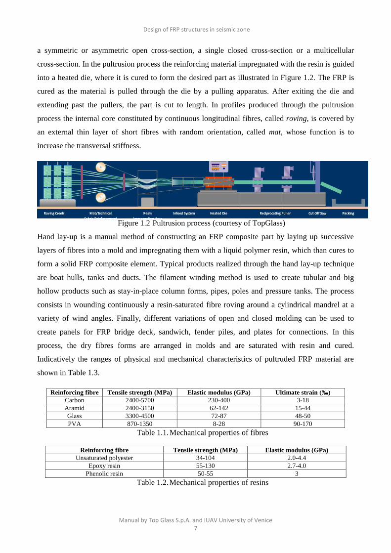
a symmetric or asymmetric open cross-section, a single closed cross-section or a multicellular
cross-section. In the pultrusion process the reinforcing material impregnated with the resin is guided
into a heated die, where it is cured to form the desired part as illustrated in Figure 1.2. The FRP is
cured as the material is pulled through the die by a pulling apparatus. After exiting the die and
extending past the pullers, the part is cut to length. In profiles produced through the pultrusion
process the internal core constituted by continuous longitudinal fibres, called roving, is covered by
an external thin layer of short fibres with random orientation, called mat, whose function is to
increase the transversal stiffness.
Figure 1.2 Pultrusion process (courtesy of TopGlass)
Hand lay-up is a manual method of constructing an FRP composite part by laying up successive
layers of fibres into a mold and impregnating them with a liquid polymer resin, which than cures to
form a solid FRP composite element. Typical products realized through the hand lay-up technique
are boat hulls, tanks and ducts. The filament winding method is used to create tubular and big
hollow products such as stay-in-place column forms, pipes, poles and pressure tanks. The process
consists in wounding continuously a resin-saturated fibre roving around a cylindrical mandrel at a
variety of wind angles. Finally, different variations of open and closed molding can be used to
create panels for FRP bridge deck, sandwich, fender piles, and plates for connections. In this
process, the dry fibres forms are arranged in molds and are saturated with resin and cured.
Indicatively the ranges of physical and mechanical characteristics of pultruded FRP material are
shown in Table 1.3.
Reinforcing fibre Tensile strength (MPa) Elastic modulus (GPa) Ultimate strain (‰)
Carbon 2400-5700 230-400 3-18 Aramid 2400-3150 62-142 15-44 Glass 3300-4500 72-87 48-50 PVA 870-1350 8-28 90-170
Table 1.1. Mechanical properties of fibres
Reinforcing fibre Tensile strength (MPa) Elastic modulus (GPa)
Unsaturated polyester 34-104 2.0-4.4 Epoxy resin 55-130 2.7-4.0
Phenolic resin 50-55 3
Table 1.2. Mechanical properties of resins

Design of FRP structures in seismic zone
Manual by Top Glass S.p.A. and IUAV University of Venice 8
Mechanical properties Notations Range values
Tensile strength (L) σZ 200-500 MPa
Tensile strength (T) σX = σY 50-70 MPa
Elastic modulus (L) EZ= EL 20-30 GPa
Elastic modulus (T) EX = EY=ET 8-8.5 GPa
Shear modulus (L) GXY=GL 3.4 GPa
In-plane shear modulus of elasticity (T) GZX=GZY=GT 3 GPa
Poisson’s ratio (L) νZX = νZY= νL 0.23-0.28
Poisson’s ratio (T) νXY= νYX= νT 0.09-0.12
Density γ 1600-2100 kg/m3
Fibres percentage in volume Vf 40%-45%
L=longitudinal, T=transversal
Table 1.3. Range of values of pultruded FRP material
In a conventional manner the FRP pultruded standard profile refers to the coordinate system defined
by the XY plane of cross-section and Z axis orthogonal to it, see again Figure 1.1. Fibres run along
the global Z axis of each element defining the anisotropic behaviour in the Z direction and isotropic
in the X and Y directions. The condition of transversal isotropy is defined by the relationships
EX=EY=ET, νXY= νYX= νT, and GXY=GT. The local co-ordinate system for the wall segments forming
the cross-section and webs and flanges is also defined, with the z-direction in the longitudinal
direction of pultrusion, x in the transverse direction and y for the through-thickness direction.
In detail, for the characterization of pultruded FRP material it must be distinguished between two
different products in function of the layering ways. A greater amount of mat increases the
transversal stiffness classifying the FRP with grade 23 (EN 13706), see Table 1.4; while a minor
percentage of mat (i.e. TopGlass standard profiles) favors the increment of longitudinal stiffness
(Table 1.5).
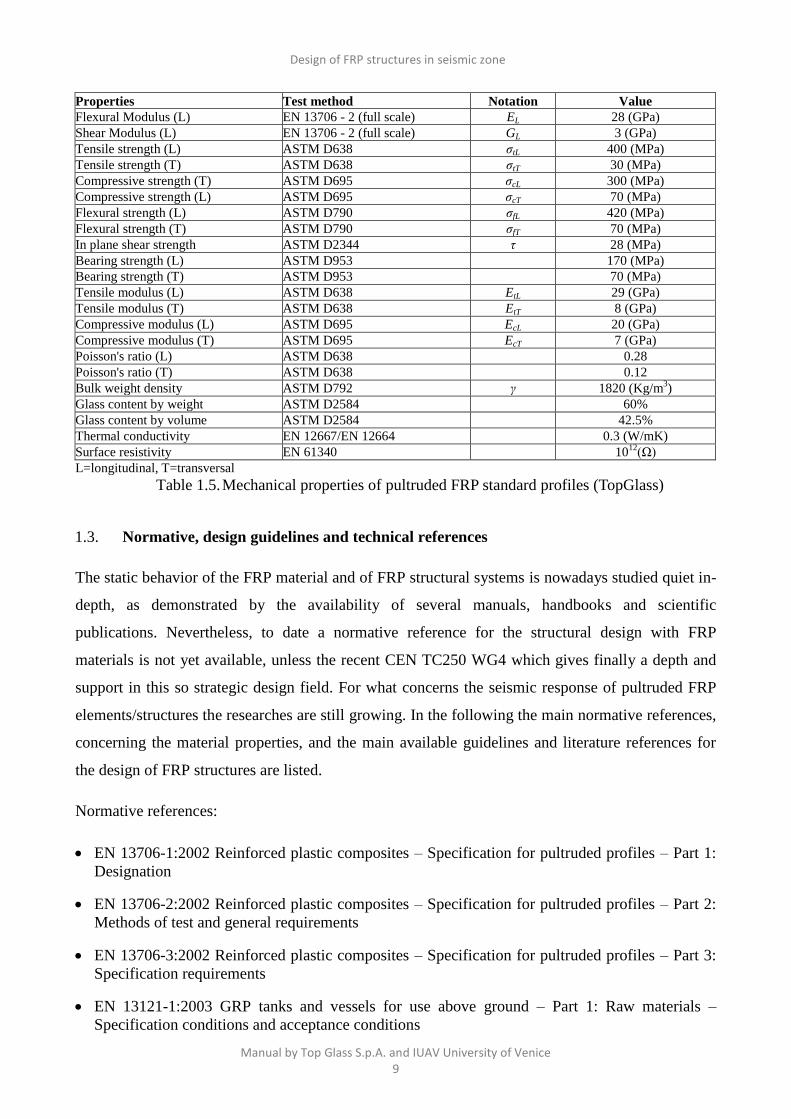
Properties Notation Value
Longitudinal tensile modulus of elasticity Ez = EL 28.5 (GPa)
Transverse tensile modulus of elasticity Ey = Ex = ET 8.5 (GPa)
Transverse shear modulus of elasticity Gyx= GL 3.5 (GPa)
In-plane shear modulus of elasticity Gxz = Gyz = GT 2.5 (MPa)
Longitudinal Poisson’s ratio νzx = νzy= νL 0.25
Transversal Poisson’s ratio νxy= νyx= νT 0.12
Bulk weight density γ 1850 (kg/m3)
Longitudinal tensile strength σzt = σLt 350 (MPa)
Transverse tensile strength σxt = σyt = σTt 70 (MPa)
Longitudinal compressive strength σzc = σLc 413 (MPa)
Transverse compressive strength σxc = σyc= σTc 80 (MPa)
Shear strength τxy= τxz = τyz 40 (MPa)
L=longitudinal, T=transversal
Table 1.4. Mechanical properties of pultruded FRP profiles (Grade E23)
Design of FRP structures in seismic zone
Manual by Top Glass S.p.A. and IUAV University of Venice 9
Properties Test method Notation Value
Flexural Modulus (L) EN 13706 - 2 (full scale) EL 28 (GPa)
Shear Modulus (L) EN 13706 - 2 (full scale) GL 3 (GPa)
Tensile strength (L) ASTM D638 σtL 400 (MPa)
Tensile strength (T) ASTM D638 σtT 30 (MPa)
Compressive strength (T) ASTM D695 σcL 300 (MPa)
Compressive strength (L) ASTM D695 σcT 70 (MPa)
Flexural strength (L) ASTM D790 σfL 420 (MPa)
Flexural strength (T) ASTM D790 σfT 70 (MPa)
In plane shear strength ASTM D2344 τ 28 (MPa)
Bearing strength (L) ASTM D953 170 (MPa)
Bearing strength (T) ASTM D953 70 (MPa)
Tensile modulus (L) ASTM D638 EtL 29 (GPa)
Tensile modulus (T) ASTM D638 EtT 8 (GPa)
Compressive modulus (L) ASTM D695 EcL 20 (GPa)
Compressive modulus (T) ASTM D695 EcT 7 (GPa)
Poisson's ratio (L) ASTM D638 0.28
Poisson's ratio (T) ASTM D638 0.12
Bulk weight density ASTM D792 γ 1820 (Kg/m3)
Glass content by weight ASTM D2584 60%
Glass content by volume ASTM D2584 42.5%
Thermal conductivity EN 12667/EN 12664 0.3 (W/mK)
Surface resistivity EN 61340 1012
(Ω)
L=longitudinal, T=transversal
Table 1.5. Mechanical properties of pultruded FRP standard profiles (TopGlass)
1.3. Normative, design guidelines and technical references
The static behavior of the FRP material and of FRP structural systems is nowadays studied quiet in-
depth, as demonstrated by the availability of several manuals, handbooks and scientific
publications. Nevertheless, to date a normative reference for the structural design with FRP
materials is not yet available, unless the recent CEN TC250 WG4 which gives finally a depth and
support in this so strategic design field. For what concerns the seismic response of pultruded FRP
elements/structures the researches are still growing. In the following the main normative references,
concerning the material properties, and the main available guidelines and literature references for
the design of FRP structures are listed.
Normative references:
EN 13706-1:2002 Reinforced plastic composites – Specification for pultruded profiles – Part 1:
Designation
EN 13706-2:2002 Reinforced plastic composites – Specification for pultruded profiles – Part 2:
Methods of test and general requirements
EN 13706-3:2002 Reinforced plastic composites – Specification for pultruded profiles – Part 3:
Specification requirements
EN 13121-1:2003 GRP tanks and vessels for use above ground – Part 1: Raw materials –
Specification conditions and acceptance conditions

Design of FRP structures in seismic zone
Manual by Top Glass S.p.A. and IUAV University of Venice 10
EN 13121-2:2003 GRP tanks and vessels for use above ground – Part 2: Composite materials –
Chemical resistance
EN 13121-3:2008 GRP tanks and vessels for use above ground – Part 3: Design and
workmanship
EN 13121-4:2005 GRP tanks and vessels for use above ground – Part 4: Delivery, installation
and maintenance
EN-ISO 14125:1998 Fibre-reinforced plastic composites. Determination of flexural properties
EN-ISO 14126:1999 Fibre-reinforced plastic composites. Determination of compressive
properties in the in-plane direction
EN-ISO 14129:1997 Fibre-reinforced plastic composites. Determination of the in-plane shear
stress/shear strain response, including the in-plane shear modulus and strength, by the ±45°
tension test method
EN-ISO 14130:1997 Fibre-reinforced plastic composites. Determination of apparent interlaminar
shear strength by short-beam method
EN 16245:2013 Fibre-reinforced plastic composites – Part 1-5: Declaration of raw material
characteristics
ASTM D 790:2010 Standard test method for flexural properties of unreinforced and reinforced
plastics and electrical insulating materials
ASTM D 2344:2006 Standard test method for short beam strength of polymer matrix composite
materials and laminates
ASTM D 3039:2008 Standard test method for tensile properties of polymer matrix composite
materials
ASTM D 3410:2008 Standard test method for compressive properties of polymer matrix
composite materials with unsupported gage section by shear loading
ASTM D 3518:2007 Standard test method for in-plane shear response of polymer matrix
composite materials by tensile test of a ±45° laminate
ASTM D 4255:2007 Standard test method for in-plane shear properties of polymer matrix
composite materials by the rail shear method
Guidelines:
CEN TC250 WG4L, Ascione, J-F. Caron, P. Godonou, K. van IJselmuijden, J. Knippers, T.
Mottram, M. Oppe, M. Gantriis Sorensen, J. Taby, L. Tromp. Editors: L.Ascione, E. Gutierrez,
S. Dimova, A. Pinto, S. Denton. ‘Prospect for New Guidance in the Design of FRP,’ Support to
the implementation and further development of the Eurocodes, JRC Science and Policy Report
JRC99714, EUR 27666 EN, European Union, Luxembourg, (2016), p 171. ISBN 978-92-79-
54225-1 doi:10.2788/22306
CUR 96 Fibre reinforced polymers in civil load bearing structures (Dutch recommendation,
1996)

Design of FRP structures in seismic zone
Manual by Top Glass S.p.A. and IUAV University of Venice 11
EUROCOMP Structural design of polymer composites (Design code and background document,
1996)
BD90/05 Design of FRP bridges and highway structures (The Highways Agency, Scottish
Executive, Welsh Assembly Government, The Department for Regional Development Northern
Ireland, 2005)
CNR-DT 205/2007 Guide for the design and construction of structures made of pultruded FRP
elements (Italian National Research Council, 2008)
ACMA Pre-standard for load and resistance factor design of pultruded fiber polymer structures
(American Composites Manufacturer Association, 2010)
DIN 13121 Structural polymer components for building and construction (2010)
ASCE, 1984, Structural Plastics Design Manual, 1984, ASCE Manual No. 63, ASCE, VA.
Books:
P. K. Mallick, Fiber-reinforced composites, Marcel Dekker Ltd., New York, 1993
D. Gay et al., Composite materials: design and applications, CRC Press, Boca Raton, 2002
L. C. Bank, Composites for construction – Structural design with FRP materials, John Wiley &
Sons Inc., New Jersey, 2006
B. D. Agarwal et al., Analysis and performance of fiber composites, John Wiley & Sons Inc.,
New Jersey, 2006
Russo, S. Strutture in composito. Sperimentazione, teoria e applicazioni, Hoepli, Milano, 2007.
Boscato G. (2011). Dynamic behaviour of GFRP pultruded elements. Published by University of
Nova Gorica Press, P.O. Box 301, Vipavska 13, SI-5001 Nova Gorica, Slovenia.
Pecce, M. and Cosenza, E., ‘FRP structural profiles and shapes, in Wiley. Encyclopedia of
Composites, 2012 - Wiley Online Library.
Dedicated conference series:
CICE (Composites in Civil Engineering)
ACIC (Advanced Polymer Composites for Structural Applications in Construction)
ICCS (International Conference on Composite Structures)
Main dedicated journals:
Advances in Structural Engineering
Applied Composite Materials
Composite Structures
Composites Part B: Engineering
Composites Science and Technology
International Journal of Adhesion and Adhesives
Journal of Composites for Construction, ASCE
Journal of Reinforced Plastics and Composites
Design of FRP structures in seismic zone
Manual by Top Glass S.p.A. and IUAV University of Venice 12
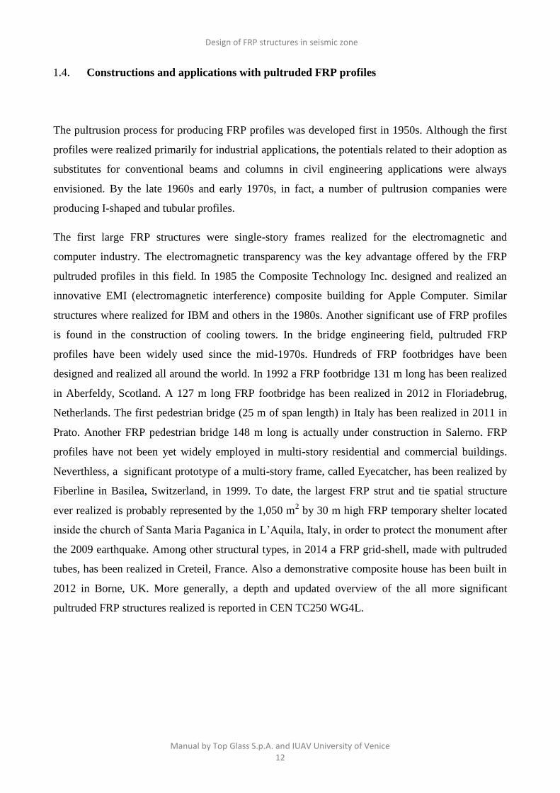
1.4. Constructions and applications with pultruded FRP profiles
The pultrusion process for producing FRP profiles was developed first in 1950s. Although the first
profiles were realized primarily for industrial applications, the potentials related to their adoption as
substitutes for conventional beams and columns in civil engineering applications were always
envisioned. By the late 1960s and early 1970s, in fact, a number of pultrusion companies were
producing I-shaped and tubular profiles.
The first large FRP structures were single-story frames realized for the electromagnetic and
computer industry. The electromagnetic transparency was the key advantage offered by the FRP
pultruded profiles in this field. In 1985 the Composite Technology Inc. designed and realized an
innovative EMI (electromagnetic interference) composite building for Apple Computer. Similar
structures where realized for IBM and others in the 1980s. Another significant use of FRP profiles
is found in the construction of cooling towers. In the bridge engineering field, pultruded FRP
profiles have been widely used since the mid-1970s. Hundreds of FRP footbridges have been
designed and realized all around the world. In 1992 a FRP footbridge 131 m long has been realized
in Aberfeldy, Scotland. A 127 m long FRP footbridge has been realized in 2012 in Floriadebrug,
Netherlands. The first pedestrian bridge (25 m of span length) in Italy has been realized in 2011 in
Prato. Another FRP pedestrian bridge 148 m long is actually under construction in Salerno. FRP
profiles have not been yet widely employed in multi-story residential and commercial buildings.
Neverthless, a significant prototype of a multi-story frame, called Eyecatcher, has been realized by
Fiberline in Basilea, Switzerland, in 1999. To date, the largest FRP strut and tie spatial structure
ever realized is probably represented by the 1,050 m2 by 30 m high FRP temporary shelter located
inside the church of Santa Maria Paganica in L’Aquila, Italy, in order to protect the monument after
the 2009 earthquake. Among other structural types, in 2014 a FRP grid-shell, made with pultruded
tubes, has been realized in Creteil, France. Also a demonstrative composite house has been built in
2012 in Borne, UK. More generally, a depth and updated overview of the all more significant
pultruded FRP structures realized is reported in CEN TC250 WG4L.
Design of FRP structures in seismic zone
Manual by Top Glass S.p.A. and IUAV University of Venice 13
Besides, it is important to outline that the characteristics of pultruded FRP profiles, such as the
reduced density, the durability and the ease of erection make them particularly suitable for the use
in the field of the reinforcing of RC (reinforced concrete) structures or traditional masonry
structures, with particular regards for historical constructions. The structural reinforcement of these
buildings through the use of pultruded FRP profiles represents an efficient solution that allows
realizing non-invasive, reversible and durable interventions for the improving of the structural
performance with a very limited added structural mass.
Examples are the reinforcement of the timber deck of the Collicola Palace in Spoleto, Italy, through
H-shaped pultruded FRP profiles; the reinforcement of roof of the San Domenico Church in Siena,
Italy; the reinforcement of the Paludo bridge in Venice, Italy, which was necessary due to the
serious deterioration of the iron structure induced by the aggressive environment conditions.
Another example of interaction between FRP structural systems and historical construction is the
realization of an auxiliary floor in the Cogollo house in Vicenza (Figure 1.3), Italy, realized in order
to optimize the available space.
Design of FRP structures in seismic zone
Manual by Top Glass S.p.A. and IUAV University of Venice 14
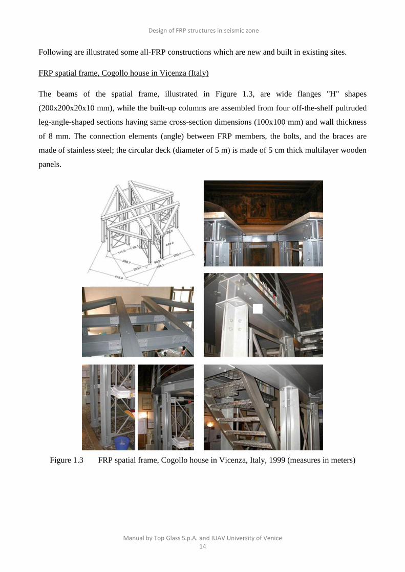
Following are illustrated some all-FRP constructions which are new and built in existing sites.
FRP spatial frame, Cogollo house in Vicenza (Italy)
The beams of the spatial frame, illustrated in Figure 1.3, are wide flanges "H" shapes
(200x200x20x10 mm), while the built-up columns are assembled from four off-the-shelf pultruded
leg-angle-shaped sections having same cross-section dimensions (100x100 mm) and wall thickness
of 8 mm. The connection elements (angle) between FRP members, the bolts, and the braces are
made of stainless steel; the circular deck (diameter of 5 m) is made of 5 cm thick multilayer wooden
panels.
Figure 1.3 FRP spatial frame, Cogollo house in Vicenza, Italy, 1999 (measures in meters)

Design of FRP structures in seismic zone
Manual by Top Glass S.p.A. and IUAV University of Venice 15
FRP auxiliary floor in Verona (Italy)
The auxiliary floor, shown in Figure 1.4, made of pultruded FRP profile, has been built in Verona
(Italy) and is constituted by:
- a double frame that with four and two vertical “I” (200x100x10 mm) FRP profiles supports,
through the steel cables, the auxiliary deck;
- the deck that is realized by coupled “I” FRP profiles that together with individual “I” profiles form
a structural grid; for all joints steel bolts and flanges have been used and the deck is realized by self
bearing panels with a capacity equal to 250 kg/ m2;
- the backstays that are steel cables of 6 mm of diameter.
Figure 1.4 Auxiliary floor, Verona, Italy, 2006 (measures in metres)

Design of FRP structures in seismic zone
Manual by Top Glass S.p.A. and IUAV University of Venice 16
Structural rehabilitation of an historic pedestrian bridge
The pedestrian “Paludo” bridge is a typical venetian bridge built at the end of XIX century, with
arch static scheme – 12.7 meters for the length and 3.25 meters for the width - built entirely with
iron and wood materials.
The flexural stiffness has been increased substituting the existing longitudinal wood beams with
double "I" shape pultruded FRP profiles (120x60x8 mm) assembled by bolted FRP plates (Figure
1.5). The details of Figure 1.5 show the workers operating facility to execute the cut (a), the holes
(b) and the final assemblage (c), the mechanical connection with the bridge abutments through the
galvanic steel gussets (d), the two “I” FRP profiles and the beam-beam joint realized through the
FRP pultruded plates and stainless bolts (e) and the final positioning in the thickness of the deck (f).
Figure 1.5 Rehabilitation of historic pedestrian bridge, Paludo bridge, Venice, Italy (2007).

Design of FRP structures in seismic zone
Manual by Top Glass S.p.A. and IUAV University of Venice 17
FRP pedestrian bridge in Prato (Italy)
The pedestrian bridge is fully made with pultruded FRP profiles, except steel bolts. The total length
of the footbridge is equal to 25 meters, with reinforced concrete piers and FRP ramps, see detail of
Figure 1.6; at the edges the access ramps have been designed with a staircase made in FRP and an
elevator. With a load bearing capacity of 5 kN/m² the bridge weighs only 8 tons. With the spatial
truss configuration the top chord is able to resist compression, while the lower chord has to resist
only to tension. The two frame trusses are strongly braced by a lateral system in the plane of its
chord in order to diminish the buckling effective length.
Figure 1.6 Plan, views and details of the spatial strut and tie all-FRP pedestrian bridge, Prato,
Italy (2013)
Design of FRP structures in seismic zone
Manual by Top Glass S.p.A. and IUAV University of Venice 18
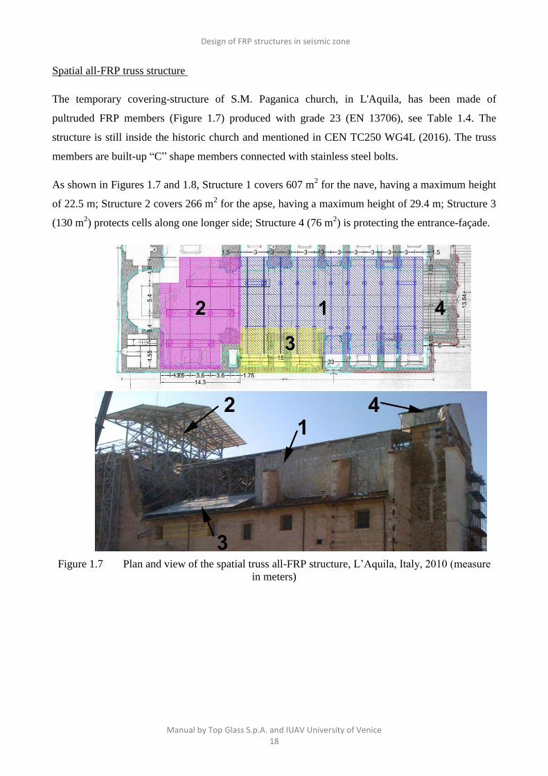
Spatial all-FRP truss structure
The temporary covering-structure of S.M. Paganica church, in L'Aquila, has been made of
pultruded FRP members (Figure 1.7) produced with grade 23 (EN 13706), see Table 1.4. The
structure is still inside the historic church and mentioned in CEN TC250 WG4L (2016). The truss
members are built-up “C” shape members connected with stainless steel bolts.
As shown in Figures 1.7 and 1.8, Structure 1 covers 607 m2 for the nave, having a maximum height
of 22.5 m; Structure 2 covers 266 m2 for the apse, having a maximum height of 29.4 m; Structure 3
(130 m2) protects cells along one longer side; Structure 4 (76 m
2) is protecting the entrance-façade.
Figure 1.7 Plan and view of the spatial truss all-FRP structure, L’Aquila, Italy, 2010 (measure
in meters)

Design of FRP structures in seismic zone
Manual by Top Glass S.p.A. and IUAV University of Venice 19
Figure 1.8 All-FRP sub-structures; L’Aquila (2010)
The frame joints use conventional steel bolts and gusset plates of FRP material made by the bag
molding process, see Figure 1.9. Detail (a) shows the built-up member’s cross-section comprising
four channel (C) profiles having same cross-section dimensions 152x46x9.5mm; while detail (b)
shows the connection between the built-up member’s cross-section of four channel (C) profiles
having same cross-section dimensions 300x100x15mm and bracings.
Figure 1.9 Details of joints of structure 1 (a) and structure 2 (b); L’Aquila (2010)

Design of FRP structures in seismic zone
Manual by Top Glass S.p.A. and IUAV University of Venice 20
2. SYNTHESIS OF BASIC PRINCIPLES FOR THE SEISMIC ANALYSIS
To facilitate the reading of this manual, in the following a short introduction in the form of sheets to
some aspects and based concepts of seismic design is presented.
1. Single Degree of Freedom (SDoF)
2. Multiple Degrees of Freedom (MDoF)
3. Natural period of vibration
4. Damping coefficient
5. Response spectra
6. Spectral analysis
7. Pushover analysis
8. Dissipative capacity
It is noted that the insights discussed in these short presentations are specific of the analyzes and
studies carried out in this manual. For more clarification, the specific texts present in the literature
and cited in every sheet are the following:
Chopra AK. Dynamics of structures, 3rd Ed., Pearson Prentice Hall, 2007.
Eurocode 8 Design of structures for earthquake resistance. Part 1: General rules, seismic actions
and rules for buildings. EN1998-1:2004 (E),: Formal Vote Version (Stage 49), 2004.
NTC08. Norme Tecniche per le Costruzioni (last update of the Italian Building Code), Decree of the
Ministry of Infrastructures of 14th January 2008. (in Italian).

Design of FRP structures in seismic zone
Manual by Top Glass S.p.A. and IUAV University of Venice 21
1- Single Degree of Freedom (SDoF)
SDoF (Single Degree of Freedom) system is characterized
by mass m and a spring with stiffness k (N/m).
The stiffness k is the external force that keeps the system
in equilibrium when a unit displacements u=1 is applied.
Dynamic equilibrium
0)()()( tumtkutp
)(tum frictions inertia force (product of mass time its
acceleration )(tk elastic stiffness force
)(tu acceleration imposed on mass
)(tp external force
Free vibration
Undamped system
The structure depends by its static equilibrium. The
system vibrates without any applied forces through the
following equation of motion:
0 kuum
Viscously damped system
The linear viscous damper (c) gives a friction in the
structure. The linear viscous damper develops a force
proportional to the velocity (fD)
)(tucfD
The equation of motion is: 0 kuucum
Assuming:
damping coefficient m
c
n
2
damped pulsation 21 nD
Equation of motion of damped system is:
02 2 uuu nn
Coulomb-damped system
The Coulomb-damped free vibration is controlled by
sliding of two dry surfaces through friction.
The friction force is F=Nμ where:
μ=equal coefficients of static and kinetic friction
N=normal force between the sliding surfaces
F=independent to velocity of the motion with direction
opposed to the motion.
The equations of motion from left to right or viceversa
are;
Fkuum
k
FtBtAtu nn )sin()cos()( 2,12,1
The constant A1, B1, A2, B2 depend on the initial
conditions.
SDoF subjected to seismic action
The equation of dynamic equilibrium is:
msv FFF
Where
vF viscoelastic force proportional to relative velocity
sF elastic force proportional to relative displacement
mF inertial force proportional to the absolute
acceleration ug
then:
))()(()()( tutumtkutuc g
and finally
))()()(2)( 2 tutututu g

Design of FRP structures in seismic zone
Manual by Top Glass S.p.A. and IUAV University of Venice 22
2a - Multiple Degrees of Freedom (MDoF)
MDoF (Multi Degrees of Freedom) is characterized by
following equation )(tpukucum
with
[m] mass matrix; [c] damping matrix; [k] stiffness matrix
Mass and stiffness matrices depend on the structure's
discretisation and on the choice of the degrees of freedom
that are involved. The damping cannot be calculated by
discretisation.
For the analysis of multiple-degrees-of-freedom (MDoF)
elastic systems, the development of the code-based
equivalent lateral force (ELF) procedure (scheme a) and
modal superposition analysis must be carried out.
In the analysis of MDoF the basic assumptions are: the
vertical and rotational masses are not required; horizontal
mass be lumped into the floors; floors are axially rigid; for
each joint (12, scheme b) three d.o.f. (degree of freedom)
must be computed (see joint 12, scheme b); motion is
predominantly lateral (see joint 4, scheme b).
The 36 static degrees of freedom may be reduced to only 3
lateral degrees of freedom for the dynamic analysis. The
three dynamic d.o.f. are u1, u2 and u3 (see scheme c).
The relative displacements not include the ground
displacements.
The flexibility matrix is simply a column-wise collection of
displaced shapes. The lateral deflection under any loading
may be represented as a linear combination of the columns
in the flexibility matrix (see schemes d, e and f).
K may be determined by imposing a unit
displacement at each DOF while restraining
the remaining DOF. The forces required to
hold the structure in the deformed position
are the columns of the stiffness matrix.
The mass matrix is obtained by imposing a
unit acceleration at each DOF while
restraining the other DOF. The columns of
the mass matrix are the (inertial) forces
required to impose the unit acceleration.
There are no inertial forces at the restrained
DOF because they do not move. Load F(t)
and displacement U(t) vary with time.
Design of FRP structures in seismic zone
Manual by Top Glass S.p.A. and IUAV University of Venice 23
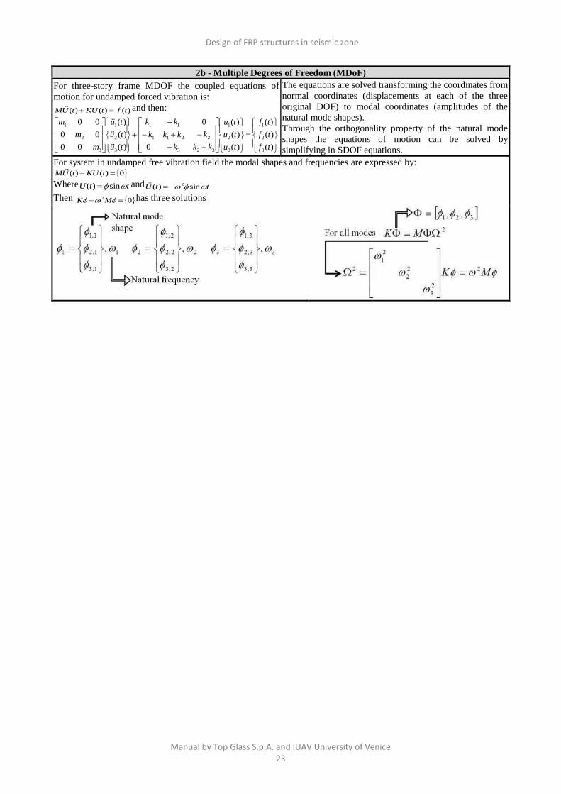
2b - Multiple Degrees of Freedom (MDoF)
For three-story frame MDOF the coupled equations of
motion for undamped forced vibration is:
)()()( tftKUtUM and then:
)(
)(
)(
)(
)(
)(
0
0
)(
)(
)(
00
00
00
3
2
1
3
2
1
323
2211
11
3
2
1
3
2
1
tf
tf
tf
tu
tu
tu
kkk
kkkk
kk
tu
tu
tu
m
m
m
The equations are solved transforming the coordinates from
normal coordinates (displacements at each of the three
original DOF) to modal coordinates (amplitudes of the
natural mode shapes).
Through the orthogonality property of the natural mode
shapes the equations of motion can be solved by
simplifying in SDOF equations.
For system in undamped free vibration field the modal shapes and frequencies are expressed by: 0)()( tKUtUM
Where ttU sin)( and ttU sin)( 2
Then 02 MK has three solutions

Design of FRP structures in seismic zone
Manual by Top Glass S.p.A. and IUAV University of Venice 24
2c - Multiple Degree of Freedom (MDoF)
Idealized mode shapes for a 3-story building
The modal shapes depend by boundary conditions;
noteworthy is the relationship between modal
shapes and nodes. The displaced shapes are obtained
by the following linear combination: YU
3
2
1
3,32,31,3
3,22,21,2
3,12,11,1
y
y
y
U
3
3,3
3,2
3,1
2
2,3
2,2
2,1
1
1,3
1,2
1,1
yyyU
Where ji, modal shape; while 1y modal
coordinate, amplitude of modal shape
The orthogonality condition 321 allows the
full uncoupling of the equations of motion: MDoF equation )(tFKUUCUM
With YU
Then )(tFYKYCYM
And )(tFYKYCYM TTTT
Obtaining the following uncoupled equations of motions
)(
)(
)(
*
3
*
2
*
1
3
2
1
*
3
*
2
*
1
3
2
1
*
3
*
2
*
1
3
2
1
*
3
*
2
*
1
tf
tf
tf
y
y
y
k
k
k
y
y
y
c
c
c
y
y
y
m
m
m
Generalized mass
*
3
*
2
*
1
m
m
m
MT
Generalized stiffness
*
3
*
2
*
1
k
k
k
KT
Generalized damping
*
3
*
2
*
1
c
c
c
CT
Generalized force
)(
)(
)(
*
3
*
2
*
1
tf
tf
tf
FT
Expliciting, with y=amplitude and *=generalized quantities
we have:
mode 1 )(*
11
*
11
*
11
*
1 tfykycym
mode 2 )(*
22
*
22
*
22
*
2 tfykycym
mode 3 )(*
33
*
33
*
33
*
3 tfykycym
Dividing by mass m* and defining
ii
ii
m
c
*
*
2
mode 1*
1
*
11
2
11111
)(2
m
tfyyy
mode 2*
2
*
22
2
22222
)(2
m
tfyyy
mode 3*
3
*
33
2
33333
)(2
m
tfyyy
MDoF system subjected to earthquake force
The inertial force = sum of two vectors through the
influence coefficient vector R; R=1 for each mass that
produces an inertial force triggered by horizontal
acceleration.
For each floor the inertial force iF is equal to mass times
M the total acceleration (ground acceleration (gu scalar)
and relative acceleration (iru ,
vector)).
)()(
)()(
)()(
)(
3,
2,
1,
tutu
tutu
tutu
MtF
rg
rg
rg
i

Design of FRP structures in seismic zone
Manual by Top Glass S.p.A. and IUAV University of Venice 25
2d - Multiple Degree of Freedom (MDoF)
Definition of modal participation factor
For earthquakes
)()(*
2 tuMRtf g
T
i
Than the typical modal equation is
)()(
2**
*2 tu
m
MR
m
tfyyy g
i
T
i
i
iiiiiii
With
i
T
i
T
i
i
T
ii
M
MR
m
MRp
*
Modal partecipation factor p with 3 first mode shape normalized, x=1
Effective modal mass for each mode i is
iii mpm 2
Where: -the sum of effective modal mass
is equal to the structural mass; -the value
of effective mass not depend by mode
shape scaling; - are needed a number of
modes to reach the activation of modal
mass at least of the 90% of the total
structural mass (as defined by standard
codes).
The effective modal mass not depend on
modal scaling as, instead, the modal
participation factor.
The modal shape is normalized, x=1

Design of FRP structures in seismic zone
Manual by Top Glass S.p.A. and IUAV University of Venice 26
3 - Natural period of vibration
The natural period of a structure T is the time needed by the structure to perform a whole oscillation, triggered by an
initial perturbation. The natural period of vibration depends by mass (m) and stiffness (k) of structure.
0
0
2
2
0
0
2
1
2
1
u
u
kk
kk
u
u
m
m
A pendulum (SDoF) with a short period of vibration (i.e. stiffer or less mass) tends to move with the support (i.e. soil)
and then not records any earthquake, a pendulum with a greater period of vibration tends to remain stationary while the
support varies.
The natural period of vibration depends by mass (m) and
stiffness (k) of structure.
The natural period of vibration T affects the response of
structure to seismic action both for the acceleration and
displacement. Buildings with different T subjected to same
seismic action record different acceleration values.
Resonance phenomenon:
the soil is also characterized by a natural period of vibration. When the natural period of vibration of the ground is very
close to that of the building, the stress of building increases.
m
k (rad/sec)
Natural circular frequency
2
1
Tf (Hz)
Natural frequency
For every structure the natural modes of vibration correspond to the number of degree of freedom and represent the free
periodic oscillations of undamped elastic system.
When the system oscillates according to one of the natural modes, all the masses oscillate with the same pulse
(corresponding to the mode) and the same phase, by keeping unchanged the relationships between the amplitudes.
For each oscillation the masses reach the point of maximum displacement in the same instant.
Adapted from Chopra (2007)

Design of FRP structures in seismic zone
Manual by Top Glass S.p.A. and IUAV University of Venice 27
Damping coefficient
The equivalent viscous damping coefficient ζ is the most used approach to analyze the dissipative capacity of structures
in dynamic field. ζ depends by effects induced by hysteretic behavior, internal friction of the material, geometrical
characteristics and typology of ground taking into account the structural response in the variation of time.
Free vibration with 10% damping coefficient ζ
Free vibration with 3% damping coefficient ζ
Logarithmic decrement method
The logarithmic decrement is an experimental approach
that takes into account a linear viscoelastic damping ζ.
To evaluate the reduction in the amplitude values that the
sinusoidal oscillatory behaviour exhibits in the time
domain, the method used is that of the logarithmic
decrement obtained from the ratio between two consecutive
maximum amplitudes in the time range of a damped period
of one or more cycles, as in:
nx
x
cn
0ln1
where δ=logarithmic decrement; cn=cycles number;
x0=initial amplitude; xn=final amplitude.
The damping coefficient (ζ) is determined through: 5.0
2
241
Equation can be simplified for small values of ζ i.e., when
(1- ζ2)
0.5 is close to 1, becoming
2
Band-width method
The Half Power Bandwidth (HPB) method in the frequency
range is employed to analyze experimentally the capacity
of the specimens to dissipate the accumulated energy from
the dynamic excitation. The bandwidth (BW) is the
frequency within a range of 3 dB, corresponding to the
measured dominant (first natural) frequency, f1, from the
action of the piling machine. This quantifies, indirectly, the
velocity from the accelerometer response from initial
frequency fi to final frequency fi+1; where fi and fi+1 are the
two frequency limits for calculating BW. Damping
coefficient ζ is given in terms of f1 and BW = (fi+1 - fi,) by
2222221 1122111221 NNfBW
where N = U/U* and U = U* - 3 dB, and U* is the peak
amplitude at f1. The relationship in Equation between ζ and
BW/f1 holds only for ζ 0.353, and by letting N=21/2
the
expression for the damping coefficient is simplified to
12 f
BW
The representation of the seismic action components is the elastic response spectrum for a conventional damping
coefficient ζ of 5%. It provides the maximum acceleration response of the generic dynamic system with natural period
of T≤4s and is expressed as the product between the spectral shape and the maximum acceleration of the ground.
On the right the deformation response factor and phase angle for a damped system.
For NTC08 and Eurocode8 the equivalent viscous damping
coefficient ζ is taken into account through the damping
correction factor η=√(10/(5+ζ))≥0.55;
This equation vales for ULS (Ultimate Limit State); then
assuming ζ=5% (reinforced concrete RC structure) we have
η=1 (unchanged spectrum); with ζ=2-3% (steel structure)
η=1.2-1.12 (amplified spectrum); while with ζ=0% η=1.41
(amplified spectrum).
In brief passing from RC to steel structure increase the
horizontal components of the design response spectrum which
tend to maximize for ζ=0, that is for a elastic structure and,
therefore, extremely rigid with respect to a dissipative structure.

Design of FRP structures in seismic zone
Manual by Top Glass S.p.A. and IUAV University of Venice 28
5a - Response spectra
SDoF Systems
SDoF system is subjected to ground motion ug(t); u(t)is
the calculated displacement response.
EQUIVALENT STATIC FORCE
fs(t)is the static force which must be applied to create the
displacement u(t)
RESPONSE SPECTRA
A response spectrum is a plot of a
maximum response, in
displacement or velocity or
acceleration form, of a SDoF
system with respect to a given
ground acceleration against
systems parameters (Tn (natural
period of vibration) and ζ
(damping coefficient)).
A response spectrum is calculated
numerically (through Duhamel
integral or time integration
methods) for (Tn and ζ). Adapted from Chopra (2007)
DETERMINATION OF RESPONSE SPECTRA
Starting from the seismic action for specific soil
characterized by )(tug :
-I apply )(tug to SDoF system with Tn and fixed
damping coefficient ζ;
-I solve the problem calculating u(t) and plotting the
graph ω2u(t)in time domain;
-I calculate the maximum value of
spectral displacements SDe={u(t)}max
spectral pseudo-velocity SVe=ω{u(t)}max
spectral pseudo-acceleration SVe=ω2{u(t)}
max
Following the relationship:
AeDe StuS2
max 1
For a given seismic action the D-V-A
(Displacement, pseudo-Velocity, pseudo-
Acceleration) elastic response spectra summarizes
the behavior in term of maximum D-V-A of all
elastic SDoF system with 0<Tn< and fixed
damping coefficient.
In detail pseudo-velocity is related to energy while
pseudo-acceleration is proportional to static load.
Combined D-V-A response spectrum for El-Centro ground motion
with ζ=0, 2, 5, 10 and 20%, (Chopra 2007).

Design of FRP structures in seismic zone
Manual by Top Glass S.p.A. and IUAV University of Venice 29
5b - Response spectra
The elastic response spectrum is obtained by many seismic events, and it isn't refered to the real earthquake.
The spectrum which characterizes the site is obtained as the envelope of the most response spectra.
The development of response spectra for a specific site requires a study of geological and seismological characteristics
of the site. It is known that the characteristics of seismic action are affected by the source that triggers the earthquake,
from the wave's directions up to the site and by local conditions.
For the equivalent static force Fsmax
The seismic analysis becomes the equivalent static
analysis.
Response spectrum (ζ =0, 2, 5 and 10%) and peak values
of ground acceleration (A), ground velocity (V) and
ground displacements (D) for i.e. El Centro ground
motion, (Chopra 2007).
For a SDOF:
The elastic design spectrum is defined through the
accelerograms recorded during past earthquakes with
similar seismic characteristics.
Construction of elastic design spectrum (Chopra 2007)
Response to El Centro earthquake (i.e.) of different
buildings changing T0 and ζ fixed:
-with higher T0 (→∞) the maximum pseudo-acceleration
→0;
-with lower T0 (→0) the maximum pseudo-acceleration
→maximum ground acceleration.
Response to El Centro earthquake (i.e.) of different
buildings changing T0 and ζ:
-the maximum displacements tend to grow with increasing
the natural period (T0)
-the maximum displacements decrease with increasing
damping coefficient (ζ)
Design of FRP structures in seismic zone
Manual by Top Glass S.p.A. and IUAV University of Venice 30
6a- Spectral analysis
The seismic loading for structural design is described by response spectra (Eurocode 8, 2004; NTC08, 2008). Design
that is in accordance with the requirements of Eurocode 8 has only ULS spectra. Working to the Italian Building Code
(NTC08 2008] requires there to be both SLS and ULS spectra.
Structures in seismic regions shall be designed and constructed taking into account the reference seismic action
associate with a reference probability of exceedance or a reference return period.
For NTC08 the seismic action depends by VR=CUxVN (where VN=service life while CU=structural class).
The period return TR= VR/(ln(1-PVr) where PVr=probability of exceedance that changes in function of the different
damage levels (SLO=operational; SLD=immediate occupancy; SLV=life safety; SLC=collapse prevention).
For EC08 the recommended values for the no-collapse requirement are PNCR=10% (probability of excedeence) and
TNCR=475 years (return period) while for the damage limitation requirement are PDLR=10% (probability of excedeence)
and TDLR=95 years (return period).
Eurocode 8, 2004 and NTC08, 2008 shall be take into account for basic informations about ground conditions, seismic
actions and general parameters.
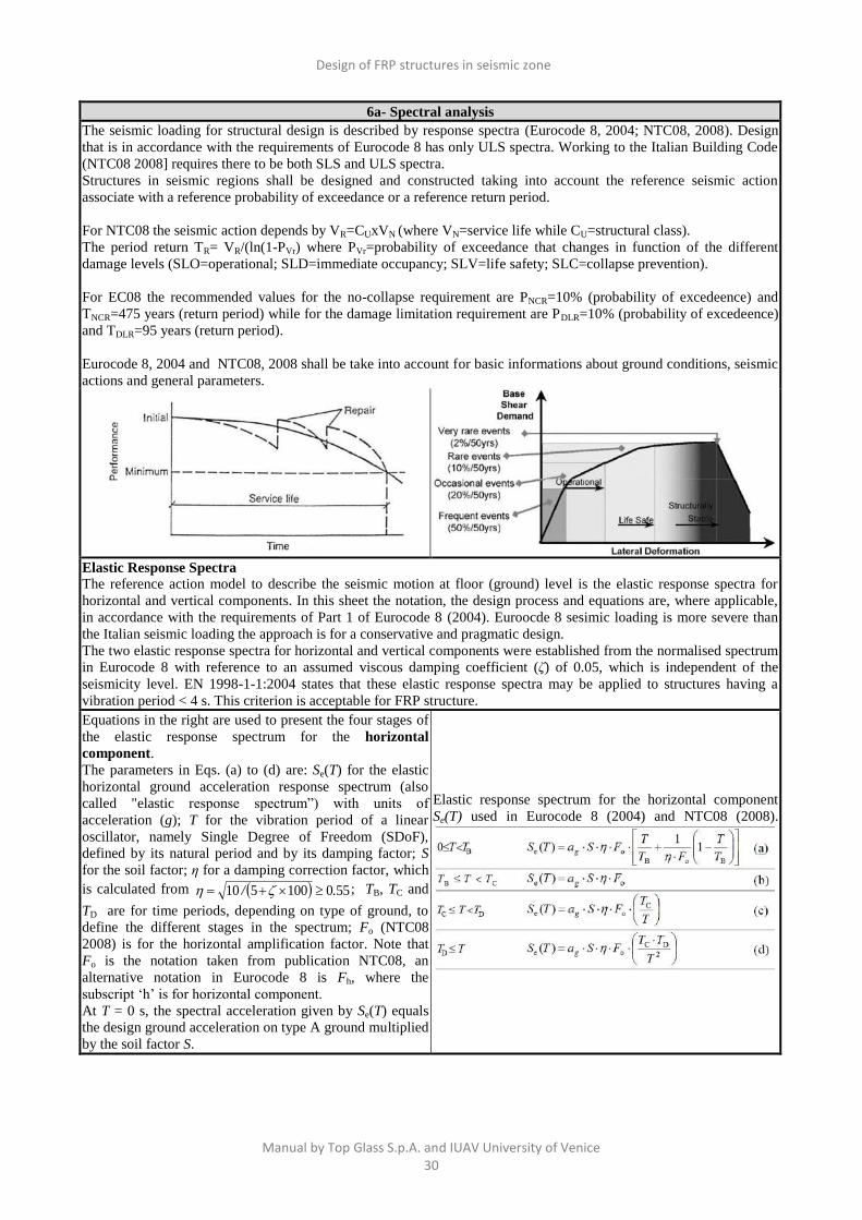
Elastic Response Spectra
The reference action model to describe the seismic motion at floor (ground) level is the elastic response spectra for
horizontal and vertical components. In this sheet the notation, the design process and equations are, where applicable,
in accordance with the requirements of Part 1 of Eurocode 8 (2004). Euroocde 8 sesimic loading is more severe than
the Italian seismic loading the approach is for a conservative and pragmatic design.
The two elastic response spectra for horizontal and vertical components were established from the normalised spectrum
in Eurocode 8 with reference to an assumed viscous damping coefficient (ζ) of 0.05, which is independent of the
seismicity level. EN 1998-1-1:2004 states that these elastic response spectra may be applied to structures having a
vibration period < 4 s. This criterion is acceptable for FRP structure.
Equations in the right are used to present the four stages of
the elastic response spectrum for the horizontal
component.
The parameters in Eqs. (a) to (d) are: Se(T) for the elastic
horizontal ground acceleration response spectrum (also
called "elastic response spectrum”) with units of
acceleration (g); T for the vibration period of a linear
oscillator, namely Single Degree of Freedom (SDoF),
defined by its natural period and by its damping factor; S
for the soil factor; η for a damping correction factor, which
is calculated from 550100510 ./ ; TB, TC and
TD are for time periods, depending on type of ground, to
define the different stages in the spectrum; Fo (NTC08
2008) is for the horizontal amplification factor. Note that
Fo is the notation taken from publication NTC08, an
alternative notation in Eurocode 8 is Fh, where the
subscript ‘h’ is for horizontal component.
At T = 0 s, the spectral acceleration given by Se(T) equals
the design ground acceleration on type A ground multiplied
by the soil factor S.
Elastic response spectrum for the horizontal component
Se(T) used in Eurocode 8 (2004) and NTC08 (2008).

Design of FRP structures in seismic zone
Manual by Top Glass S.p.A. and IUAV University of Venice 31
6b- Spectral analysis
The elastic response spectrum for the vertical ground
acceleration (Sve(T)) is defined by the four expressions in
the right Table. In Equs. (a) to (d) the new parameters
respect to horizontal component are: avg for the design
ground acceleration in the vertical direction that is given by
0.9 ag and Fv for the vertical amplification factor that is
given by 1.35Fh(avg/g)0.5
.
Elastic response spectrum for the vertical component Sve(T)
used in Eurocode 8 (2004) and NTC08 (2008).
The horizontal component of acceleration is always higher than in the vertical direction. It can be seen that the elastic
response spectra from Eurocode 8 are significantly higher, and have different time differentials, than those obtained on
using NCT08.
Design spectra for ULS design
For the purpose of seismic design the dissipation capacity of any structure can be taken into consideration by
introducing a reduction factor to the elastic spectral accelerations. This is accomplished in Eurocode 8 (2004) and in
Italian Building Code (NCT08, 2008) by introducing q.
To ensure the structural design for the structure could be conservative, and when the material plasticity is minimal, the
factor q was set to be 1.0. In other words there was no reduction in the spectrum’s accelerations for the structural
analysis to establish the seismic performance.
Displacement response spectra
To gain an insight into how much horizontal displacement the structure is to experience due to ground movement the
displacement response spectrum, SDe(T), is obtained from the acceleration response spectrum (Se(T)), by using the
relationship:2
eDe2
)()(
TTSTS

Design of FRP structures in seismic zone
Manual by Top Glass S.p.A. and IUAV University of Venice 32
7 - Pushover analysis
In performance-based engineering it is necessary to obtain realistic estimates of inelastic deformations in structures so
that these deformations may be checked against deformation limits as established in the appropriate performance
criteria. Two basic methods are available for determining these inelastic deformations: Nonlinear static “pushover”
analysis and Nonlinear Dynamic Response History analysis.
In the non linear static analysis method a structure is subjected to gravity loading and a displacement-controlled
lateral load pattern which continuously increases through elastic and inelastic behavior until an ultimate condition is
reached. Lateral load may represent the range of base shear induced by earthquake loading.
Different types of non linear behaviour exist: mechanical (connected to the non linearity of the material), geometrical
(connected to the fact that the application point of the loads changes increasing the actions) and of beam-column
joints (connected to the interaction of structural elements).
The pushover analysis is based on: 1-Definition of capacity curve of MDoF system; 2-Definition of equivalent SDoF
system; 3-Calculation of capacity displacement (umax); 4-Calculation of displacement demand (dmax); 5-Comparison
between umax and dmax; 6-Validation when umax >dmax (see figure below).
The capacity curve= relationship between the horizontal displacement and horizontal force.
The demand curve is basically an elastic response spectrum that has been modified for expected performance and
equivalent viscous damping. The demand curve is used in concert with the capacity curve to predict the target
displacement.
The expected displacement is determined locating on the capacity curve the displacement compatible with the seismic
action of the site. The identification of this displacement is pursued by operating in Acceleration Displacement
Response Spectrum (ADRS), and then describing the capacity curve and the response spectrum in terms of spectral
acceleration and spectral displacement. In the space ADRS the response spectrum and capacity curve should
respectively take the name of the Demand spectrum and Capacity spectrum capacity. The different forms of horizontal actions are:
a)Uniform load proportional to the mass distribution
b)Triangular load proportional to the mass distribution
c)Horizontal load proportional to the lateral force distribution of the mode with the highest mass participation
‘‘Modal’’.
The P-Δ effect must be taken into account. The P-Δ effect is a destabilizing moment equal to the force of gravity
multiplied by the horizontal displacement a structure undergoes when loaded laterally.

Design of FRP structures in seismic zone
Manual by Top Glass S.p.A. and IUAV University of Venice 33
8a – Dissipative capacity
For the seismic design the dissipation capacity of any structure can be taken into consideration by introducing a
reduction factor to the elastic spectral accelerations. This is accomplished in standard codes by the behaviour factor q.
The design seismic action Sd(T) is given by the elastic response spectra with the elastic accelerations (forces) adjusted
downward by dividing by q. The determination of the q depends on the: materials; structural form; hyperstaticity degree
of structure; structural response (e.g. its ductility); soil-structure interaction. To ensure the structural design for the
structure could be conservative the factor q =1.0. In other words there was no reduction in the spectrum’s accelerations
in the elastic response spectrum for the structural analysis to establish the seismic performance.
The q factor is determined through kinematic or energetic equivalence conditions.
Kinematic equivalence for structure with higher period of
vibration
qu
u
F
Fq
yy
e max
Energetic equivalence for structure with short period of
vibration
221 max yy
e
y
e
u
u
u
u
F
F
12212 qq
Hence, considering the previous criteria
sifTq
sTsifq
sifTq
1.01
5.01.012
5.0
Generalizing the SDoF, the q of MDoF could be evaluated through the relationship between the different peek ground
acceleration (PGA) of collapse and yielding state:
y
u
PGA
PGAq
or through the pushover analysis considering the static forces equivalent to seismic actions:
y
uq
Elastic response spectra in SLS for horizontal and vertical
components based on Eurocode 8 (2004) and NTC08 (2008).
Design response spectrum for ULS structural analysis
based on using Eurocode 8 (2004) and NTC08 (2008).
Design of FRP structures in seismic zone
Manual by Top Glass S.p.A. and IUAV University of Venice 34
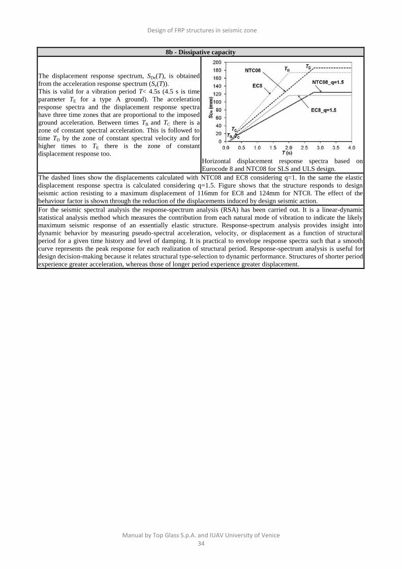
8b - Dissipative capacity
The displacement response spectrum, SDe(T), is obtained
from the acceleration response spectrum (Se(T)).
This is valid for a vibration period T< 4.5s (4.5 s is time
parameter TE for a type A ground). The acceleration
response spectra and the displacement response spectra
have three time zones that are proportional to the imposed
ground acceleration. Between times TB and TC there is a
zone of constant spectral acceleration. This is followed to
time TD by the zone of constant spectral velocity and for
higher times to TE there is the zone of constant
displacement response too. Horizontal displacement response spectra based on
Eurocode 8 and NTC08 for SLS and ULS design.
The dashed lines show the displacements calculated with NTC08 and EC8 considering q=1. In the same the elastic
displacement response spectra is calculated considering q=1.5. Figure shows that the structure responds to design
seismic action resisting to a maximum displacement of 116mm for EC8 and 124mm for NTC8. The effect of the
behaviour factor is shown through the reduction of the displacements induced by design seismic action.
For the seismic spectral analysis the response-spectrum analysis (RSA) has been carried out. It is a linear-dynamic
statistical analysis method which measures the contribution from each natural mode of vibration to indicate the likely
maximum seismic response of an essentially elastic structure. Response-spectrum analysis provides insight into
dynamic behavior by measuring pseudo-spectral acceleration, velocity, or displacement as a function of structural
period for a given time history and level of damping. It is practical to envelope response spectra such that a smooth
curve represents the peak response for each realization of structural period. Response-spectrum analysis is useful for
design decision-making because it relates structural type-selection to dynamic performance. Structures of shorter period
experience greater acceleration, whereas those of longer period experience greater displacement.


![Seismic Zone Map of Myanmar[2]](https://static.fdocuments.net/doc/165x107/563db8f8550346aa9a98be04/seismic-zone-map-of-myanmar2.jpg)


