![Influence of processing parameters and sintering ...ijens.org/Vol_12_I_01/120301-8484-IJMME-IJENS.pdf · biocompatibility, and insufficient affinity for cells and tissues [5, 6].](https://static.fdocuments.net/doc/165x107/5e5d8b01c516560c80780ba8/influence-of-processing-parameters-and-sintering-ijensorgvol12i01120301-8484-ijmme-ijenspdf.jpg)
Design of EMG Acquisition Circuit to Control an...
11
International Journal of Mechanical & Mechatronics Engineering IJMME-IJENS Vol:17 No:05 37 I J E N S IJENS © October 2017 IJENS - IJMME - 3 9 93 - 172505 Design of EMG Acquisition Circuit to Control an Antagonistic Mechanism Actuated by Pneumatic Artificial Muscles PAMs 3 Alkhayat M. Mouath * and 2 Nibras Abo Alzahab * , 1 Hassan AlImam * 1. Teaching Assistant, Mechanical Design Engineering Department, Faculty of Mechanical and Electrical Engineering, Damascus University,[email protected] 2. Undergraduate Student, Biomedical Engineering Department, Faculty of Mechanical and Electrical Engineering, Damascus University,[email protected] 3. Assistant professor, Mechanical Design Engineering Department, Faculty of Mechanical and Electrical Engineering, Damascus University,[email protected] *. The experimental work was divided equally, and the names’ order does not matter. Abstract--A pneumatically actuated antagonistic pair of muscles with joint mechanism (APMM) is supported and developed to be essential for bionic and biomimetic applications to emulate the biological muscles by realizing various kinds of locomotion based on normal electrical activity of biological muscles. This Paper aims to compare the response of antagonistic pairs of muscles mechanism (APMM) based on the pneumatic artificial muscles (PAMs) to an EMG signal that was acquired throw a designed circuit and an EMG Laboratory acquisition kit. The response is represented as a joint rotary displacement generated by the contraction and extension of the pneumatic artificial muscles. A statistical study was done to prove the efficiency of the designed circuit the response of antagonistic pairs of muscles mechanism. The statistical result showed that there is no significant difference of voltage data in both EMG acquired signal between reference kit and designed circuit. An excellent correlation behavior between the EMG control signal and the response of APMM as an angular displacement has been discussed and statistically analyzed. Index Term-- Pneumatic Artificial Muscles, Biomechatronics, Electromyogram EMG, Pneumatic Proportional Directional Control Valve, Signal Processing, Bionic. I. INTRODUCTION The innovation in bio robotic systems is involving various numbers of Mechatronics and bionic applications which require actuators to drive the motion of this system. Pneumatic artificial muscles (PAMs) actuators are commonly used in various Mechatronics applications such as artificial lower and upper limb rehabilitation devices, biomechanical systems and industrial applications [1] [2] [3] [4]. The importance of using pneumatic artificial muscles (PAMs) is to reach a smoother and more natural movement pattern according to its favorable properties similar to the biological muscles. To achieve this goal, applying Electromyography (EMG) signal to control pneumatic artificial muscles (PAMs) plays a key role. Electromyography (EMG) has been widely used to control upper limb assistive rehabilitation devices, such as orthosis devices, which can supply external power to the limb or used for limb rehabilitation [5] [6]. These devices are called exoskeletons which refer to any electromechanical system that is able to be worn as an armor covering or wrapping around the said limb to enhance its capacity beyond its natural powers or to restore the function of weak limbs. Exoskeleton robots are developed because of the importance of enhancing human capacity which is limited to certain weights that a human can carry [6][7][8][9]. Michał A. Mikulski in [10] proposed control algorithms for EMG-based powered exoskeleton used for physiotherapy and rehabilitation. The upper limp single Degree-Of-Freedom (DOF) exoskeleton was built using linear electric actuators. M.N.Shah et. al. in [11] introduced an automated device to perform the repetitive tasks on patients that physiotherapy treatment requires. H.He and K.Kiguchi in [12] proposed EMG-based control for the robotic exoskeleton to assist lower-limp motion for the physically weak patient. The changing EMG levels which accommodate the different user’s psychological and physical conditions were taken into account. Pieter Beyl et. al. in [13] considered pneumatic muscles a reasonable choice to be utilized as a part of powered exoskeletons because of its intrinsic compliance and high force-to-weight proportions. Dongjun Shin et. al. used in their research the antagonistic actuation system based on PAMs to discuss and analyze the effect of Varity in radius of circular pulley joint in improving
Transcript of Design of EMG Acquisition Circuit to Control an...

International Journal of Mechanical & Mechatronics Engineering IJMME-IJENS Vol:17 No:05 37
I J E N S IJENS © October 2017 IJENS -IJMME-3993-172505
Design of EMG Acquisition Circuit to Control an
Antagonistic Mechanism Actuated by Pneumatic
Artificial Muscles PAMs
3Alkhayat M. Mouath*and2Nibras Abo Alzahab*,1Hassan AlImam*
1. Teaching Assistant, Mechanical Design Engineering Department, Faculty of Mechanical and Electrical Engineering,
Damascus University,[email protected]
2. Undergraduate Student, Biomedical Engineering Department, Faculty of Mechanical and Electrical Engineering, Damascus
University,[email protected]
3. Assistant professor, Mechanical Design Engineering Department, Faculty of Mechanical and Electrical Engineering, Damascus
University,[email protected]
*. The experimental work was divided equally, and the names’ order does not matter.
Abstract--A pneumatically actuated antagonistic pair of muscles
with joint mechanism (APMM) is supported and developed to be
essential for bionic and biomimetic applications to emulate the
biological muscles by realizing various kinds of locomotion based
on normal electrical activity of biological muscles. This Paper
aims to compare the response of antagonistic pairs of muscles
mechanism (APMM) based on the pneumatic artificial muscles
(PAMs) to an EMG signal that was acquired throw a designed
circuit and an EMG Laboratory acquisition kit. The response is
represented as a joint rotary displacement generated by the
contraction and extension of the pneumatic artificial muscles. A
statistical study was done to prove the efficiency of the designed
circuit the response of antagonistic pairs of muscles mechanism.
The statistical result showed that there is no significant
difference of voltage data in both EMG acquired signal between
reference kit and designed circuit. An excellent correlation
behavior between the EMG control signal and the response of
APMM as an angular displacement has been discussed and
statistically analyzed.
Index Term-- Pneumatic Artificial Muscles, Biomechatronics,
Electromyogram EMG, Pneumatic Proportional Directional
Control Valve, Signal Processing, Bionic.
I. INTRODUCTION
The innovation in bio robotic systems is involving various
numbers of Mechatronics and bionic applications which
require actuators to drive the motion of this system. Pneumatic
artificial muscles (PAMs) actuators are commonly used in
various Mechatronics applications such as artificial lower and
upper limb rehabilitation devices, biomechanical systems and
industrial applications [1] [2] [3] [4].
The importance of using pneumatic artificial muscles (PAMs)
is to reach a smoother and more natural movement pattern
according to its favorable properties similar to the biological
muscles. To achieve this goal, applying Electromyography
(EMG) signal to control pneumatic artificial muscles (PAMs)
plays a key role. Electromyography (EMG) has been widely
used to control upper limb assistive rehabilitation devices,
such as orthosis devices, which can supply external power to
the limb or used for limb rehabilitation [5] [6]. These devices
are called exoskeletons which refer to any electromechanical
system that is able to be worn as an armor covering or
wrapping around the said limb to enhance its capacity beyond
its natural powers or to restore the function of weak limbs.
Exoskeleton robots are developed because of the importance
of enhancing human capacity which is limited to certain
weights that a human can carry [6][7][8][9].
Michał A. Mikulski in [10] proposed control algorithms for
EMG-based powered exoskeleton used for physiotherapy and
rehabilitation. The upper limp single Degree-Of-Freedom
(DOF) exoskeleton was built using linear electric actuators.
M.N.Shah et. al. in [11] introduced an automated device to
perform the repetitive tasks on patients that physiotherapy
treatment requires.
H.He and K.Kiguchi in [12] proposed EMG-based control for
the robotic exoskeleton to assist lower-limp motion for the
physically weak patient. The changing EMG levels which
accommodate the different user’s psychological and physical
conditions were taken into account.
Pieter Beyl et. al. in [13] considered pneumatic muscles a
reasonable choice to be utilized as a part of powered
exoskeletons because of its intrinsic compliance and high
force-to-weight proportions.
Dongjun Shin et. al. used in their research the antagonistic
actuation system based on PAMs to discuss and analyze the
effect of Varity in radius of circular pulley joint in improving
International Journal of Mechanical & Mechatronics Engineering IJMME-IJENS Vol:17 No:05 38
I J E N S IJENS © October 2017 IJENS -IJMME-3993-172505
torque capacity while maintaining a work space range based
on the static mechanical properties of this mechanism [14].
Yusuke Hashimoto et. al. in [15] developed a gait-assistive
device constructed with pneumatic artificial muscles (PAMs)
and uses EMG as an input signal.
Based on signals acquired by human muscle activities and
PAMs actuators, a new rehabilitation system was developed
by Jun-ichiro Furukawa et.al. to compare the performance of
this support system by means of normal activity acquired by
leg muscles in for experimental condition [16].
Yong Zhu in [17] developed a prototype Ankle Foot Orthosis
(AFO) applying the sensors’ measurements of smart phones,
such as gyroscopes and accelerometers. The developed AFO
prototype is actuated with a pneumatic artificial muscle
(PAM).
The most important bio mechanical mechanism, which are
still frequently used to simulate and modeling the one link
bionic arm “biceps-triceps –elbow joint system”, is
Antagonistic pairs of muscles which have been actuated by
Pneumatic artificial muscles (PAM). In previous studies,
many researchers from different university have been studying
the behavior, mechanical and mathematical modeling and
control method of Antagonistic mechanism to innovate an
orthosis, prosthesis and bio Mechatronic systems actuated by
this pneumatic flexible actuator [18] [19]. As cited in many
scientific papers, PAMs were used as an adaptive actuator in
rehabilitation and bionic systems according to their similarity
to biological muscles [20][21][22][23].
Pneumatic artificial muscles (PAMs) are defined as a single
acting actuator like a tube including a flexible and contractile
membrane contracts axially and expands radially when the air
pressure inside the muscle is increased. Moreover, the
contraction of this actuator can be controlled by decreasing
and increasing the gas pressure inside it
[24][25][26][27][28][29].
Pneumatic artificial muscles have been considered as
substitute actuator to hydraulic and electric actuators after
being used as an unprecedented actuator according to their
sophisticated technical properties [30],and special mechanical
properties similar to biological muscle such as light simplicity,
inexpensive power source , low cost , cleanliness ,inherent
safety, elasticity, flexibility, lightweight, spring
characteristics, high strength, high power-to-weight ratio and a
high power/volume ratio[31]. According to this properties
PAMs has been widely used in bionics and biomechanical
applications and in the field of rehabilitation and prostheses
devices [32][33][34][35][36].
Typically, Antagonistic pairs of pneumatic muscles
mechanisms (APMM) were controlled by electro pneumatic
proportional valve using the closed loop control methods
based on the feedback from force and position sensors
[37][38]. Furthermore, scarcely any researches were
conducted using open loop control system depending on an
acquired EMG signal. In this paper, we compare the response
of pneumatic artificial muscle, used in antagonistic
mechanism and driven by proportional directional valve, to
the EMG signal which was acquired by a reference EMG
device and the one acquired by a designed circuit by the
research team.
II. METHODOLOGY A. Experimental setup and Characteristic of Antagonistic
Pairs of Muscles Mechanism (APMM)
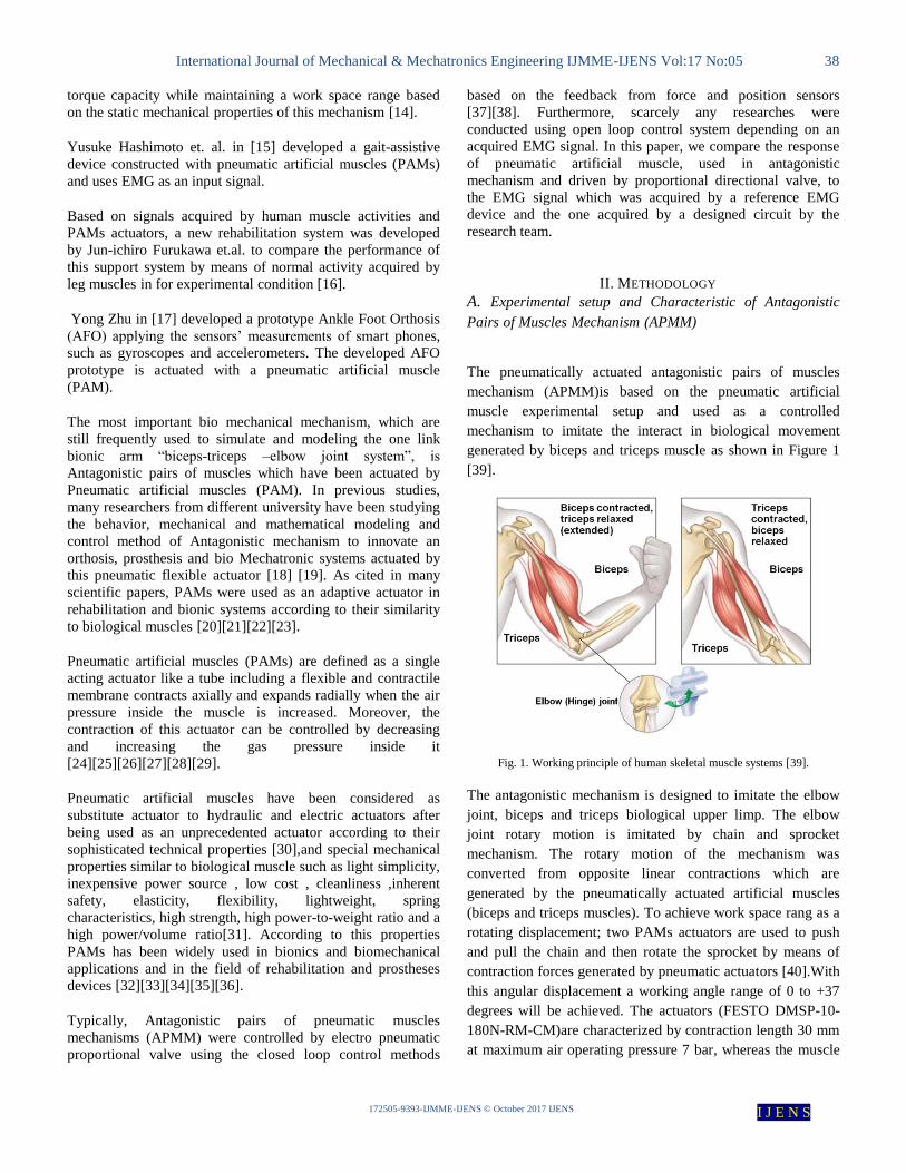
The pneumatically actuated antagonistic pairs of muscles
mechanism (APMM)is based on the pneumatic artificial
muscle experimental setup and used as a controlled
mechanism to imitate the interact in biological movement
generated by biceps and triceps muscle as shown in Figure 1
[39].
Fig. 1. Working principle of human skeletal muscle systems [39].
The antagonistic mechanism is designed to imitate the elbow
joint, biceps and triceps biological upper limp. The elbow
joint rotary motion is imitated by chain and sprocket
mechanism. The rotary motion of the mechanism was
converted from opposite linear contractions which are
generated by the pneumatically actuated artificial muscles
(biceps and triceps muscles). To achieve work space rang as a
rotating displacement; two PAMs actuators are used to push
and pull the chain and then rotate the sprocket by means of
contraction forces generated by pneumatic actuators [40].With
this angular displacement a working angle range of 0 to +37
degrees will be achieved. The actuators (FESTO DMSP-10-
180N-RM-CM)are characterized by contraction length 30 mm
at maximum air operating pressure 7 bar, whereas the muscle

International Journal of Mechanical & Mechatronics Engineering IJMME-IJENS Vol:17 No:05 39
I J E N S IJENS © October 2017 IJENS -IJMME-3993-172505
internal diameter is 10 mm. Only one data acquisition
component is employed to collect the feedback from angular
position generated by this APMM, therefore a rotary encoder
sensor (OPKON PRID 50 ARS LTP 1000 Z V2) is assembled
with sprocket spindle. Opposite contractions of the actuators
are controlled by a5-ports – 3-ways proportional servo valve
(FESTO MPYE-5-1/8LF-010-B) which is connected to both
artificial muscles. In order to measure air pressure in the two
PAM, two pressure sensors were connected to the working
ports between the servo valve and the pneumatics artificial
muscles. Air pressure is injected to the servo valve from
pressure supply compressor through pressure regulator from
service unite under absolute pressure value 7 bar. Pneumatic
diagram design of the Antagonistic mechanism based on
FESTO FluidSIM Pneumatics software version 4.2 with two
artificial muscles is shown in figure 2.
Fig. 2. Pneumatic diagram of Experimental system
B. Experimental platform of Antagonistic Pairs of Muscles
Mechanism
Two electronic circuits and an open source micro controller
circuit were established for experimental platform of
antagonistic mechanism, the following circuits include: EMG
Laboratory acquisition kit, EMG acquisition circuit designed
by research team, Arduino Mega2560 microcontroller for
open loop control and position sensor feedback acquisition
and PWM signal converter to analogue signal and low pass
filter circuit. A photograph of the experiment system is shown
in Figure 3.
Fig. 3. Photo of antagonistic pairs of muscles mechanism experimental system
A. Experimental platform:1. Arduino Mega2560 board, 2.
10V power supply, 3. Conditioning circuit, 4. Designed EMG
acquisition circuit. B. Experimental setup: 5. Pneumatic
service unit, 6. Manifold, 7. Proportional directional control
valve, 8. Rotary encoder, 9. Chain & Sprocket, 10. Pneumatic
artificial muscles, 11. Pressure sensors, 12. Air Compressor.
C. Experimental system: 13. Oscilloscope, 14. 24 V Power
supply. 15. Personal computer.
C. Acquired reference signal
The Reference EMG signal was acquired using KL-72001
BIOSIGNALS MESURMENT SYSTEM and KL-75002
ELECTROMYOGRAM EMG MODULE, the EMG
Laboratory acquisition kit, which consist of signal acquisition
part and enveloping part. The signal acquisition part has a
pre-amplifier, isolator, band reject filter, low pass filter, gain
amplifier and high pass filter. Enveloping part has a full-wave
rectifier and integration and buffer block. Figure 4
demonstrates a real photo of the kit.

International Journal of Mechanical & Mechatronics Engineering IJMME-IJENS Vol:17 No:05 40
I J E N S IJENS © October 2017 IJENS -IJMME-3993-172505
Fig. 4. Photo of EMG Laboratory acquisition kit
D. EMG Signal Acquisition
EMG signal acquisition is an increasing aspect in the field of
bionics research. The concept of EMG signal acquisition is the
use of electrodes attached to the desired muscle to collect the
signal which is a small signal that contains noise. The noise in
the collected signal could be removed by using instrumental
amplifier and filtering. The acquired signal could be used as a
control signal after being rectified and enveloped. Rectifying
EMG signal plays a significant role to obtain the shape or
“envelop” of the signal. The EMG signal in our project was
acquired throw INA118 instrumental amplifier, digital
rectifier and digital filtering [41][42].
E. Electrodes
Electrodes area key issue that directly affects the quality of the
acquired signal. Two types of electrodes are mainly used to
obtain EMG signal, invasive inserted electrodes and non-
invasive surface electrodes. The advantage of using needle
invasive electrodes is to obtain a clear signal with high signal-
to-noise ratio which makes it very accurate in diagnosing
muscle illness. Surface electrodes are easy to use with
acceptable signal-to-noise ratio which makes it suitable for the
application of bionics. Surface electrodes were used in this
research as they are non-invasive, therefore easy to be used
[41][43]. Electrodes placement with EMG signal acquisition
designed circuit is illustrated in figure 5.
F. Pre-amplifier
Pre-amplifier stage is used for two main purposes. Firstly, to
reject the common mode that causes added noise to the signal.
Secondly, amplifying the single in order to transfer it from the
range of mV to the range of volt, so it could be sampled via
Arduino. The pre-amplifier has an instrumental amplifier
INA118 and two operational amplifiers LM741. By using
INA118 instrumental amplifier, an excellent amplifying
properties will be achieved which include: low power and
high common-mode rejection (110dB at G = 1000) with
excellent accuracy [44].The gain G could be determined by
connecting external resistors that set any gain from 1 to
10,000 according to the equation (1) [45]:
G = 1 +50 kΩ
RG (1)
Where RG is the external resistor that sets the gain value.
The designed pre-amplifier circuit schematic diagram is
shown in figure 6. The circuit was designed and simulated by
Proteus 8 professional software by Lab center Electronics Ltd.
R1, R2, R3 and R4 comprise RG. From the mid-point of R1,
R2, R3 and R4, a signal is fed into LM741 to generate a
reference potential. Each R1, R2, R3 and R4 is 10Ω, therefore
the gain value G is equal to 1251 according to the equation
(1).
Fig. 5. Electrodes placement with pre-amplifier circuit
Fig. 6. The designed pre-amplifier circuit schematic diagram

International Journal of Mechanical & Mechatronics Engineering IJMME-IJENS Vol:17 No:05 41
I J E N S IJENS © October 2017 IJENS -IJMME-3993-172505
G. Signal Sampling
Sampling analog signal into Arduino Mega2560 board is
achieved by the embedded analog-to-digital converter (ADC)
using 10 bits resolution. Sampling rate should commit to
Nyquist frequency “a sinusoid can only be correctly recreated
if it is sampled at no less than twice its frequency” i.e.
sampling rate frequency should be at least twice the highest
frequency component in the signal[46], whereas the highest
frequency component in biceps muscle EMG signal is 450 Hz
[43][47]. To sample EMG signal, 9615.38 Hz sampling rate
frequency is used. This could be calculated by dividing 16Mz,
which is the ADC clock, by a prescale factor that is set to a
default value equals to 128 (16MHz/128 = 125 KHz). The
conversion takes 13 ADC clocks; hence the sample rate is
about 125KHz/13 or 9615.38 Hz [48]. The signal was sampled
into Arduino Mega2560 board and transferred to MATLAB
Software version r2016 where it was saved as .txt file to be
filtered later [49].
H. Signal Processing
In order to obtain a useful signal which could be used as a
control signal, it should be denoised, rectified and filtered
[50]. The first step in EMG signal processing is to delete the
DC component which is caused by the environment and the
circuit noise. Deleting DC component was done by MATLAB
function “detrend”. The second step is to take the absolute
value of the signal which is called full wave rectification in
order to obtain the shape or “envelop” of the signal. Signal
rectification was done by MATLAB function “abs”. If the
EMG signal is filtered and smoothed without being rectified a
zero value is the result, which shows the importance of
rectification. Thirdly, filtering and smoothing the signal was
achieved by the usage of 5th order Butterworth digital low pass
filter with 450Hz cut-off frequency. The filter was built by
MATLAB function “butter(5,450/9600,'low')” and
applied by MATLAB function “filtfilt”. In order to
make the signal easy to be used, it was digitally amplified [47]
[49] [51].
I. Conditioning Circuit
The aim of this step is to transform the output signal from
Arduino Mega2560 board, 5V PWM signal with frequency of
490Hz, to adapt the proportional directional control valve’s
analog set point voltage, which is in the range of 0 to 10V. To
achieve the required input characteristics of the proportional
valve, a conditioning circuit was designed and used. The
circuit is consisted of three main sections. Firstly, PC817
isolator was used to protect the Arduino Mega2560 board.
Secondly, C2328 transistor-based amplifier is used in
saturation mode with 10V supplement. Thirdly, a low pass
filter with 450Hz cut-off frequency smooths the PWM signal
which results an analog-like signal with 10V maximum value.
Figure 7 represents the schematic diagram of designed
conditioning circuit.
Fig. 7. Schematic diagram of designed conditioning circuit with conditioning
steps
J. Data analysis
Statistical analysis was used to study the EMG acquired signal
data and antagonistic pairs of muscles mechanism response to
the control signal [52] [53]. Data were analyzed using
software Statistical Package version 17.0. Paired Samples T
Test was employed to examine if there is any significance
difference between means for two EMG voltage data
(Acquired by designed circuit & Reference kit). The
significant level was set at statistical significance level 0.05.
To describe and analyze the relationship between EMG
control signal (Acquired by designed circuit & Reference kit)
data and angular position values and to determine the degree
of correlation between studied variables, Bivariate Correlate
test was employed in Statistical analysis with correlation
coefficient (Pearson’s Correlation r) at statistical significance
level 0.01 [54]. EMG signal data and statistical results were
compared and further discussed.
III. RESULT AND DISCUSSION
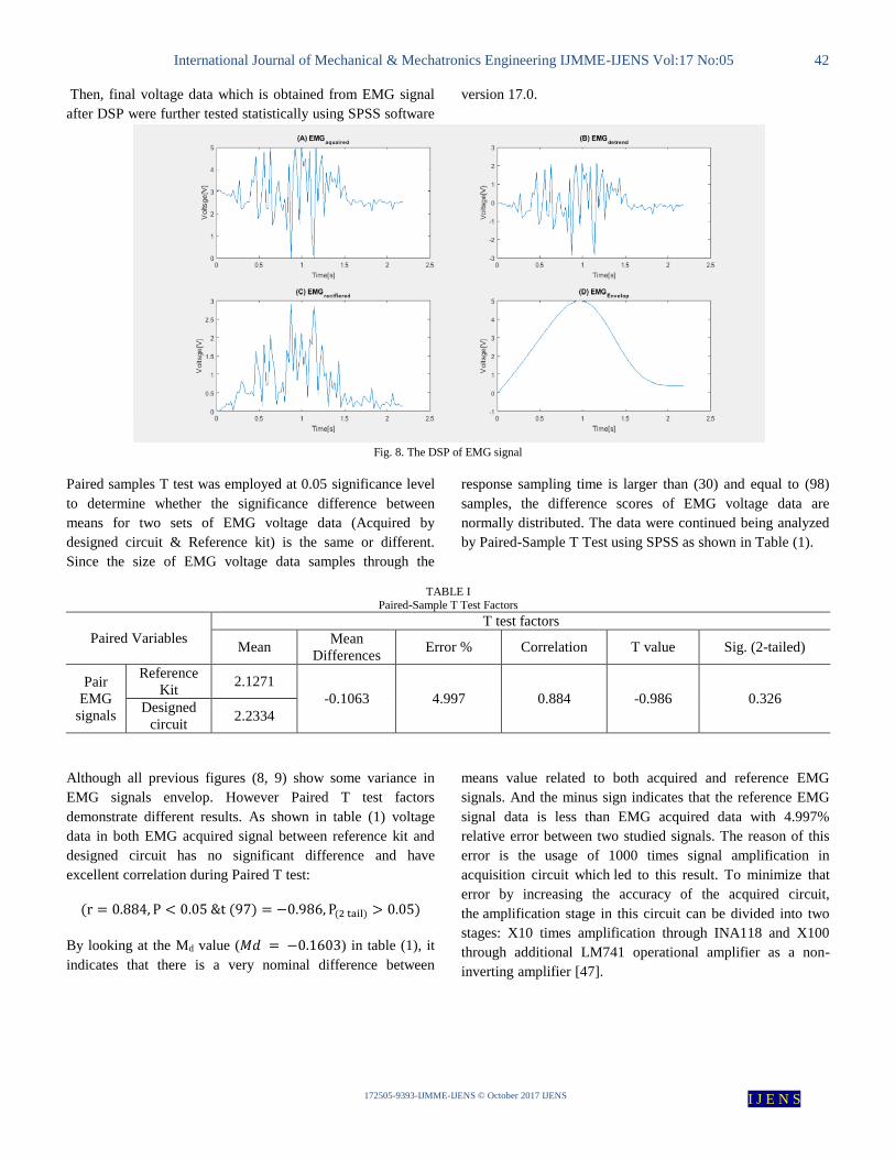
Digital signal processing (DSP) was carried out using
MATLAB Software version r2016. For acquired EMG signal
the DSP procedure is consisted of three steps: Removing DC
offset, EMG signal rectifier and filtering with amplifying final
signal to maximum 5 V amplitude voltage (signal envelop). In
the otherwise, EMG reference signal was only rectified and
amplified. The response of EMG signals with time through
DSP steps are shown in figure 8 and figure 9.
International Journal of Mechanical & Mechatronics Engineering IJMME-IJENS Vol:17 No:05 42
I J E N S IJENS © October 2017 IJENS -IJMME-3993-172505
Then, final voltage data which is obtained from EMG signal
after DSP were further tested statistically using SPSS software
version 17.0.
Fig. 8. The DSP of EMG signal
Paired samples T test was employed at 0.05 significance level
to determine whether the significance difference between
means for two sets of EMG voltage data (Acquired by
designed circuit & Reference kit) is the same or different.
Since the size of EMG voltage data samples through the
response sampling time is larger than (30) and equal to (98)
samples, the difference scores of EMG voltage data are
normally distributed. The data were continued being analyzed
by Paired-Sample T Test using SPSS as shown in Table (1).
TABLE I
Paired-Sample T Test Factors
Paired Variables T test factors
Mean Mean
Differences Error % Correlation T value Sig. (2-tailed)
Pair
EMG
signals
Reference
Kit 2.1271
-0.1063 4.997 0.884 -0.986 0.326 Designed
circuit 2.2334
Although all previous figures (8, 9) show some variance in
EMG signals envelop. However Paired T test factors
demonstrate different results. As shown in table (1) voltage
data in both EMG acquired signal between reference kit and
designed circuit has no significant difference and have
excellent correlation during Paired T test:
(r = 0.884, P < 0.05 &t (97) = −0.986, P(2 tail) > 0.05)
By looking at the Md value (𝑀𝑑 = −0.1603) in table (1), it
indicates that there is a very nominal difference between
means value related to both acquired and reference EMG
signals. And the minus sign indicates that the reference EMG
signal data is less than EMG acquired data with 4.997%
relative error between two studied signals. The reason of this
error is the usage of 1000 times signal amplification in
acquisition circuit which led to this result. To minimize that
error by increasing the accuracy of the acquired circuit,
the amplification stage in this circuit can be divided into two
stages: X10 times amplification through INA118 and X100
through additional LM741 operational amplifier as a non-
inverting amplifier [47].

International Journal of Mechanical & Mechatronics Engineering IJMME-IJENS Vol:17 No:05 43
I J E N S IJENS © October 2017 IJENS -IJMME-3993-172505
Fig. 9. The DSP of EMG reference signal
After proving that there is no significant difference between
two EMG acquired signals, the signals were used as a control
signal to control opposite linear contractions related to PAM
by means of Proportional control valve. Whereas the EMG
signal is conditioned to achieve the required input
characteristics of the proportional valve with voltage range (0-
10 V). EMG control signals are depicted in figure 10. The
response of Antagonistic Pairs of Muscles Mechanism to
control EMG control signals which are represented in sprocket
rotary displacement is shown in figure (11, 12). Figure (11)
illustrates that the rotary displacement reaches a maximum
angular position (37°) with maximum EMG control signals
amplitude and it is decreased by reveres linear contraction of
PAM which is generated by decreasing the EMG signal value.
To examine and analyze the strength of the relationship
between EMG control signal and angular position, Bivariate
correlation test was employed at 0.01 significance level. Data
illustrated in table 1 confirms that there is a significant
positive relationship exist between EMG control signal
(Acquired by designed circuit & Reference kit) and angular
position, test scours were strongly correlate
(rEMG Reference (98) = +0.812, P <
0.01) &(rEMG circuit (98) = +0.819, P < 0.01).
Thus higher angular position values are related to higher EMG
voltage data.

International Journal of Mechanical & Mechatronics Engineering IJMME-IJENS Vol:17 No:05 44
I J E N S IJENS © October 2017 IJENS -IJMME-3993-172505
TABLE II Bivariate Correlation Test Factors
Correlation variables Correlation test factors
Mean Pearson Correlation coefficient
EMG (Reference) control signal
&
angular position
4.25428 +0.812
19.03631
EMG (Designed circuit) control signal &
angular position
4.46674 +0.819
19.05214
Fig. 10. EMG control signals (A. Acquired by Designed Circuit, B. Acquired by Reference kit)
Fig. 11. Response of APMM to EMG control signals (acquired by designed circuit)

International Journal of Mechanical & Mechatronics Engineering IJMME-IJENS Vol:17 No:05 45
I J E N S IJENS © October 2017 IJENS -IJMME-3993-172505
Fig. 12. Response of APMM to EMG control signals (acquired by Reference kit)
IV. CONCLUSIONS
The paper discusses the concerns related to EMG signal
aquatinting and filtering and the response of antagonistic pairs
of PAMs mechanism as the rotation of the sprocket. The
experimental system show high reliability in performance,
which was divided into two main parts: Experimental platform
and Experimental setup. Two statistical tests were carried out
to the extracted features. Based on the results have been
obtained from this study, the comparison between reference
kit and designed circuit shows that there are no significant
difference between EMG acquired signals voltage data. A
strong relationship between the EMG control signal and the
response of APMM as an angular displacement can be
concluded. Depending on the results of the statistical study of
the experiment results, the designed circuit is as effective as
the EMG Laboratory acquisition kit and it is able to
successfully acquire EMG signal and convert it into a control
signal. This reliability in performance is commensurate with
the low value of the cost of manufacturing this circuit
compared to the laboratory kit and other commercial circuits.
The total cost of manufacturing this circuit is 9 USD, which is
only in the range of (4% to 10%) of the price of the laboratory
kit according to its originality and manufacturing sources.
Unfortunately, the angle of rotation is only 37° which is not
effective to be applied in an exoskeleton device.
V. FUTURE STUDIES
In order to make this system able to be worn as an exoskeleton
device, many features could be added. Increasing the range of
rotation requires increasing of the contraction length. In order
to achieve absolute angle of rotation, a closed loop control
system must be applied e.g. Proportional, Integral, Differential
(PID) control system. The most important enhancement of the
system is that it could be used in Brain-Computer Interface
(BCI) based exoskeletons as a stimulation signal trigger
response.
ACKNOWLEDGMENT
This study was not funded by any grant. The authors would
like to thank the staff of Automatic Control and Industrial
Automation ACIA Laboratory, and Biomedical Engineering
Department in the Faculty of Mechanical and Electrical
Engineering; Thanks go also to Prof. Mahmoud Bani Al-
Marjeh Head of Mechatronics Department in Damascus
University for his valuable comments and discussions on this
research.
REFERENCES [1] T. F. Tang, S. H. Chong, M. H. Tan, C. Y. Chan, K. Sato.
“Characterization of pneumatic artificial muscle system in an
opposing pair configuration.” Journal of Telecommunication,
Electronic and Computer Engineering Vol. 8 No. 2 (2016): 73-77.
[2] T. Karnjanaparichat and R. Pongvuthithum. “Adaptive control for
a one-link robot arm actuated by pneumatic muscles.” Chiang Mai
J. Sci. 35(3) (2008): 437-446.
[3] G. Belforte, G. Eula, Al. Ivanov and Si. Sirolli. “Soft pneumatic
actuators for rehabilitation.” Actuators 3 (2014): 84-106. [4] K. Hosoda, T. Takuma, and M. Ishikawa, “Design and Control of a
3D Biped Robot Actuated by Antagonistic Pairs of Pneumatic
Muscles,” in Proc. of Int. Symposium. on Adaptive Motion in
Animals and Machines, Darmstadt (2005).
[5] Furukawa, Jun-ichiro, et al. "Fault tolerant approach for biosignal-
based robot control." Advanced Robotics 29.7 (2015): 505-514.
[6] Gopura, R. A. R. C., et al. "Developments in hardware systems of
active upper-limb exoskeleton robots: A review." Robotics and
Autonomous Systems 75 (2016): 203-220.
[7] Pons, José L. Wearable robots: biomechatronic exoskeletons. John Wiley & Sons, 2008.
[8] Mohammed, Samer, YacineAmirat, and HalaRifai. "Lower-limb
movement assistance through wearable robots: State of the art and challenges." Advanced Robotics 26.1-2 (2012): 1-22.
[9] Rukina, N. N., et al. "Surface electromyography: its role and
potential in the development of exoskeleton." Современныетехнологии в медицине 8.2 (eng)
(2016).
[10] Mikulski, Michal A. "Electromyogram control algorithms for the upper limb single-dof powered exoskeleton." Human System
Interactions (HSI), 2011 4th International Conference on. IEEE,
2011. [11] M.N.Shah, S.N. Basah, K.S.Basaruddin, W.K.W. Ahmad .
“Forward Kinematics Modeling and Verification of a 3-DOF
Cable Driven Ankle Rehabilitation Robot”. International Journal of Mechanical & Mechatronics Engineering IJMME-IJENS.Vol:17
No:03 (2017): 53-63.
[12] He, H., &Kiguchi, K. (2007, November). A study on emg-based control of exoskeleton robots for human lower-limb motion assist.

International Journal of Mechanical & Mechatronics Engineering IJMME-IJENS Vol:17 No:05 46
I J E N S IJENS © October 2017 IJENS -IJMME-3993-172505
In Information Technology Applications in Biomedicine, 2007. ITAB 2007. 6th International Special Topic Conference on (pp.
292-295). IEEE.
[13] He, H., and K. Kiguchi. "A study on emg-based control of exoskeleton robots for human lower-limb motion
assist." Information Technology Applications in Biomedicine, 2007. ITAB 2007. 6th International Special Topic Conference on. IEEE,
2007.
[14] Shin, Dongjun, XiyangYeh, and Oussama Khatib. "Variable radius pulley design methodology for pneumatic artificial muscle-based
antagonistic actuation systems." Intelligent Robots and Systems
(IROS), 2011 IEEE/RSJ International Conference on. IEEE, 2011. [15] Hashimoto, Yusuke, et al. "Development of Gait Assistive Device
Using Pneumatic Artificial Muscle." Soft Computing and
Intelligent Systems (SCIS) and 17th International Symposium on Advanced Intelligent Systems, 2016 Joint 8th International
Conference on. IEEE, 2016.
[16] Furukawa, Jun-ichiro, et al. "An emg-driven weight support system with pneumatic artificial muscles." IEEE Systems
Journal 10.3 (2016): 1026-1034.
[17] Yong Zhu. Design and Web-based Control of a Soft Ankle Foot Orthosis. International Journal of Mechanical & Mechatronics
Engineering IJMME-IJENS.Vol:17 No:01(2017): 82-88.
[18] Sakthivelu, Vasanthan, et al. "Phenomenological Modeling and Classic Control of a Pneumatic Muscle Actuator
System." International Journal of Control and Automation 9.4
(2016): 301-312. [19] Pujana-Arrese, Aron, et al. "Modelling in Modelica and position
control of a 1-DoF set-up powered by pneumatic
muscles." Mechatronics 20.5 (2010): 535-552. [20] Tóthová, M., and Jan Pitel. "Simulation of actuator dynamics
based on geometric model of pneumatic artificial
muscle." Intelligent Systems and Informatics (SISY), 2013 IEEE 11th International Symposium on. IEEE, 2013.
[21] Andrikopoulos, George, George Nikolakopoulos, and Stamatis
Manesis. "Novel Considerations on Static Force Modeling of Pneumatic Muscle Actuators." IEEE/ASME transactions on
mechatronics 21.6 (2016): 2647-2659.
[22] Sawicki, Gregory S., and Daniel P. Ferris. "A pneumatically powered knee-ankle-foot orthosis (KAFO) with myoelectric
activation and inhibition." Journal of neuroengineering and
rehabilitation 6.1 (2009): 23. [23] Caldwell, Darwin G., et al. " Soft exoskeletons for upper and lower
body rehabilitation—design, control and testing." International
Journal of Humanoid Robotics 4.03 (2007): 549-573. [24] Pipan, Miha, et al. "New Pneumatic Artificial Muscle Force Model
Using Machine Vision Volume Measurement and Virtual Work."
[25] Wickramatunge, KanchanaCrishan, and Thananchai Leephakpreeda. "Study on mechanical behaviors of pneumatic
artificial muscle." International Journal of Engineering
Science 48.2 (2010): 188-198. [26] Honda, Yuki, Fumio Miyazaki, and Atsushi Nishikawa. "Control
of pneumatic five-fingered robot hand using antagonistic muscle
ratio and antagonistic muscle activity." Biomedical Robotics and Biomechatronics (BioRob), 2010 3rd IEEE RAS and EMBS
International Conference on. IEEE, 2010.
[27] Plattenburg, D. H. "Pneumatic actuators: a comparison of energy-
to-mass ratio's." Rehabilitation Robotics, 2005. ICORR 2005. 9th
International Conference on. IEEE, 2005. [28] Sárosi, József. "Newest approach to modeling hysteresis in the
Force-contraction cycle of pneumatic artificial muscle." Acta
Technica Corviniensis-Bulletin of Engineering 5.4 (2012): 63. [29] Aguilar-Sierra, Hipolito, et al. "A lower limb exoskeleton with
hybrid actuation." Biomedical Robotics and Biomechatronics
(2014 5th IEEE RAS & EMBS International Conference on. IEEE, 2014.
[30] Lin, Liu Hsu, Jai Yush Yen, and Fu Cheng Wang. "System
Identification and Robust Control of a Pneumatic Muscle Actuator System", Applied Mechanics and Materials, 2013.
[31] Wang, Shaofei, and Kaiji Sato. "High-precision motion control of
a stage with pneumatic artificial muscles", Precision Engineering,
2016.
[32] Tsagarakis, N. G., and N. G. Caldwell. "A Compliant exoskeleton
for multi-planar upper limb physiotherapy and training." Advanced
Robotics, Invited Paper,(submitted) (2007).
[33] Aguilar-Sierra, Hipolito, et al. "Design and control of hybrid
actuation lower limb exoskeleton." Advances in Mechanical
Engineering 7.6(2015):1687814015590988.
[34] Berns, K., et al. "Control of a six-legged robot using fluidic
muscle." International Conference on Advanced Robotics.2001. [35] Schreiber, Frank, et al. "Model-based controller design for
antagonistic pairs of fluidic muscles in manipulator motion
control." Methods and Models in Automation and Robotics
(MMAR), 2012 17th International Conference on. IEEE,2012.
[36] Das, G. Kumar Hari Shankar Lal, et al. "Controlling a multi-joint
arm actuated by pneumatic muscles with quasi-DDP optimal
control." Intelligent Robots and Systems (IROS), 2016 IEEE/RSJ
International Conference on. IEEE,2016.
[37] Ján .P and T. Mária. "Operating Characteristics of Antagonistic
Actuator with Pneumatic Artificial Muscles." Applied Mechanics
& Materials 616 (2014).
[38] Day, Scott. "Important factors in surface EMG
measurement." Bortec Biomedical Ltd publishers (2002): 1-17.
[39] Reece, Taylor, Simon, Dickey, Hogan. “PowerPoint Lectures
Campbell Biology: Concepts & Connections, Chapter 30 How
animal move: Eighth Edition”. Pearson Education, Inc.(2015)
Available:
https://www.pearson.com/us/higher-education/program. [40] Wang, Shaofei, Kaiji Sato, and Toshiharu Kagawa. "Precise
Positioning of Pneumatic Artificial Muscle Systems",Journal of
Flow Control Measurement & Visualization,2014.
[41] Clancy, Edward A., Evelyn L. Morin, and Roberto Merletti.
"Sampling, noise-reduction and amplitude estimation issues in
surface electromyography." Journal of Electromyography and
Kinesiology 12.1 (2002): 1-16.
[42] J. Lu. de Souza Ramos M. An. Meggiolaro. “Use of surface
electromyography to control an active upper limb exoskeleton
actuated by pneumatic artificial muscles and optimized with
genetic algorithms.” ABCM Symposium Series in Mechatronics.
Vol. 6.(2016): 757-768.
[43] De Luca, Gianluca. "Fundamental concepts in EMG signal
acquisition." Copyright Delsys Inc (2003).
[44] http://radiodetail.narod.ru/nelikvidu/INA118.html.
[45] INA118 Datasheet. 1994 Burr-Brown Corporation.
[46] Wang, Jianhua, Guoyu Lang, and Weihai Chen." A high accuracy
signal processing system forsix-dimensional force
sensor",201325th Chinese Control and Decision Conference
(CCDC),2013.
[47] Rainoldi, A., et al. "Repeatability of surface EMG variables during
voluntary isometric contractions of the biceps brachii
muscle." Journal of Electromyography and Kinesiology 9.2
(1999): 105-119.
[48] http://www.glacialwanderer.com/robots/tutorials/loadingProgramO
nPIC16F877.html
[49] Bianchi, André Jucovsky, and Marcelo Queiroz. "Real time digital
audio processing using Arduino."
(2012).Available:http//www.ime.usp.br/~ajb/conferencias/smc201
3/arduino-rtdsp-smc2013.pdf
[50] Wang, Jingpeng, Liqiong Tang, and John E. Bronlund. "Surface
EMG signal amplification and filtering." International Journal of
Computer Applications 82.1 (2013).

International Journal of Mechanical & Mechatronics Engineering IJMME-IJENS Vol:17 No:05 47
I J E N S IJENS © October 2017 IJENS -IJMME-3993-172505
[51] Clinical Biomechanics Research Group, Clinical Research Centre
for Health Professions, University of Brighton. (2006, July).
Analysis of Electromyographic Data [Online]. Available:
http://www.biomech.uottawa.ca/english/teaching/apa6905/lab/Mat
Lab%20Help%20-%20EMG%20Analysis.pdf
[52] M. Sarillee, M. Hariharan, M.N. Anas, M.I. Omar, and M.N.
Aishah. “Statistical Investigation of Muscle Fatigue using Multi-
Sensors” International Journal of Mechanical & Mechatronics
Engineering IJMME-IJENS. Vol:16 No02 (2016): 79-84.
[53] H. Harun, N.F. Mohd Nasir, A.F. Salleh. “The Study of Lower
Limb EMG Signals Between Male and Female Muslim during
Pertaining to Sujud Postures in Solat.”International journal of
electrical and electronic systems research. Vol. 9(2016).
[54] Hassan Alimam, Mahmoud Hinnawi and Kholoud Alzain,
'Statistical Study Evaluation of Correlation Between Organic
Coating Thickness and Three Hardness Test Methods',
International Research Journal (ISSN 2303-9868), vol. 44, no. 2,
pp. 55-61. 2016.


![The Effects of Shot Peening Treatment on the Corrosion ...ijens.org/Vol_18_I_04/183304-9292-IJMME-IJENS.pdf · treatment which can be used for components with complex geometry [14].](https://static.fdocuments.net/doc/165x107/5ea2b58bb1aa5501227aa30c/the-effects-of-shot-peening-treatment-on-the-corrosion-ijensorgvol18i04183304-9292-ijmme-ijenspdf.jpg)