Design of Electronic Code Lock Circuit under Internet of ...
4
Design of Electronic Code Lock Circuit under Internet of Things System Wei Hu Information Center, Daqing Oilfield Limited Company, 163453.Dqing. China Keywords: EPC System, Internet of Things, LCD, the minimum system SCM. Abstract. This paper design of a electronic code lock circuit under EPC system network. the system mainly including the minimum system SCM, password input matrix keyboard, password storage circuit, unlock circuit, LCD display circuit, buzzer alarm circuit and VD indicator circuit. The main program flow chart complete the system initialization, password settings, and then enter the main loop for keyboard scanning and display. 1. Design Tasks and Requirements 1. Design an electronic password lock with LCD display and storage function, free to modify the password. 2. Electronic password lock has alarm function, when the continuous input and error three times the password lock will cause the attention of people around to prevent the thief repeatedly try to open [1-2] . 3. Equipped with relay control, you can use the password to control large electrical operation. 2. Design Scheme According to the design requirements [3-4] , the whole system program structure is shown in Figure 1, the system mainly including the minimum system SCM, password input matrix keyboard, password storage circuit, unlock circuit, LCD display circuit, buzzer alarm circuit and VD indicator circuit. Singlechip Minimum System Keyboard Password storage circuit Unlocking control circuit LCD Buzzer alarm LED Instructions Fig. 1 Block diagram of system International Conference on Advances in Materials, Machinery, Electrical Engineering (AMMEE 2017) Copyright © 2017, the Authors. Published by Atlantis Press. This is an open access article under the CC BY-NC license (http://creativecommons.org/licenses/by-nc/4.0/). Advances in Engineering Research, volume 114 208
Transcript of Design of Electronic Code Lock Circuit under Internet of ...
Design of Electronic Code Lock Circuit under Internet of Things System
Wei Hu Information Center, Daqing Oilfield Limited Company, 163453.Dqing. China
Keywords: EPC System, Internet of Things, LCD, the minimum system SCM.
Abstract. This paper design of a electronic code lock circuit under EPC system network. the system mainly including the minimum system SCM, password input matrix keyboard, password storage circuit, unlock circuit, LCD display circuit, buzzer alarm circuit and VD indicator circuit. The main program flow chart complete the system initialization, password settings, and then enter the main loop for keyboard scanning and display.
1. Design Tasks and Requirements
1. Design an electronic password lock with LCD display and storage function, free to modify the password.
2. Electronic password lock has alarm function, when the continuous input and error three times the password lock will cause the attention of people around to prevent the thief repeatedly try to open[1-2].
3. Equipped with relay control, you can use the password to control large electrical operation.
2. Design Scheme
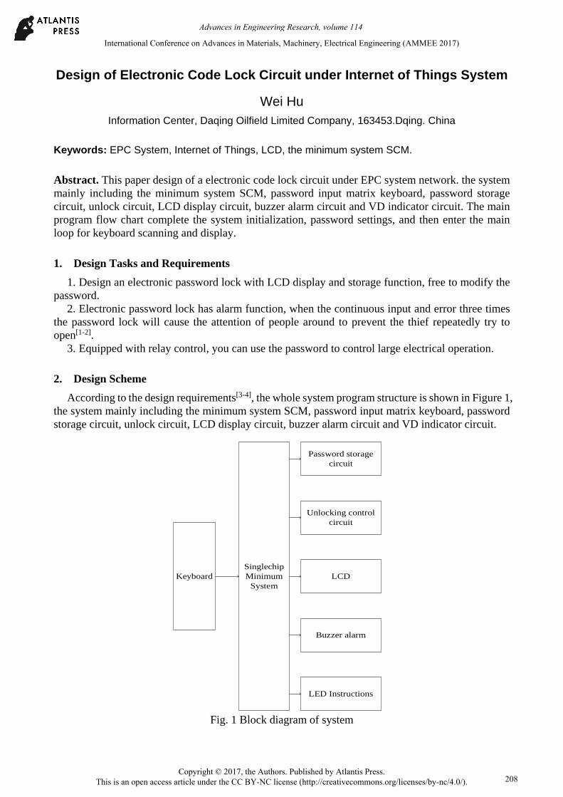
According to the design requirements[3-4], the whole system program structure is shown in Figure 1, the system mainly including the minimum system SCM, password input matrix keyboard, password storage circuit, unlock circuit, LCD display circuit, buzzer alarm circuit and VD indicator circuit.
Singlechip Minimum
SystemKeyboard
Password storage circuit
Unlocking control circuit
LCD
Buzzer alarm
LED Instructions
Fig. 1 Block diagram of system
International Conference on Advances in Materials, Machinery, Electrical Engineering (AMMEE 2017)
Copyright © 2017, the Authors. Published by Atlantis Press. This is an open access article under the CC BY-NC license (http://creativecommons.org/licenses/by-nc/4.0/).
Advances in Engineering Research, volume 114
208
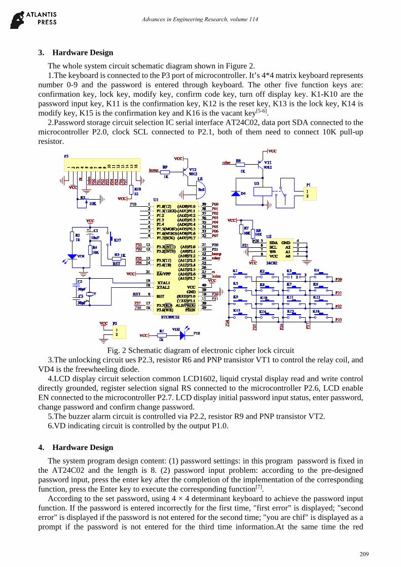
3. Hardware Design
The whole system circuit schematic diagram shown in Figure 2. 1.The keyboard is connected to the P3 port of microcontroller. It’s 4*4 matrix keyboard represents
number 0-9 and the password is entered through keyboard. The other five function keys are: confirmation key, lock key, modify key, confirm code key, turn off display key. K1-K10 are the password input key, K11 is the confirmation key, K12 is the reset key, K13 is the lock key, K14 is modify key, K15 is the confirmation key and K16 is the vacant key[5-6].
2.Password storage circuit selection IC serial interface AT24C02, data port SDA connected to the microcontroller P2.0, clock SCL connected to P2.1, both of them need to connect 10K pull-up resistor.
Fig. 2 Schematic diagram of electronic cipher lock circuit
3.The unlocking circuit ues P2.3, resistor R6 and PNP transistor VT1 to control the relay coil, and VD4 is the freewheeling diode.
4.LCD display circuit selection common LCD1602, liquid crystal display read and write control directly grounded, register selection signal RS connected to the microcontroller P2.6, LCD enable EN connected to the microcontroller P2.7. LCD display initial password input status, enter password, change password and confirm change password.
5.The buzzer alarm circuit is controlled via P2.2, resistor R9 and PNP transistor VT2. 6.VD indicating circuit is controlled by the output P1.0.
4. Hardware Design
The system program design content: (1) password settings: in this program password is fixed in the AT24C02 and the length is 8. (2) password input problem: according to the pre-designed password input, press the enter key after the completion of the implementation of the corresponding function, press the Enter key to execute the corresponding function[7].
According to the set password, using 4 × 4 determinant keyboard to achieve the password input function. If the password is entered incorrectly for the first time, "first error" is displayed; "second error" is displayed if the password is not entered for the second time; "you are chif" is displayed as a prompt if the password is not entered for the third time information.At the same time the red
Advances in Engineering Research, volume 114
209
light-emitting diode is lit, the buzzer issued a continuous drop alarm. The password can be changed at any time during the process of entering the password. The system design consists of keyboard input part, liquid crystal display part, diode prompt part and external control part.
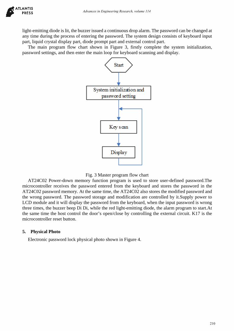
The main program flow chart shown in Figure 3, firstly complete the system initialization, password settings, and then enter the main loop for keyboard scanning and display.
Fig. 3 Master program flow chart
AT24C02 Power-down memory function program is used to store user-defined password.The microcontroller receives the password entered from the keyboard and stores the password in the AT24C02 password memory. At the same time, the AT24C02 also stores the modified password and the wrong password. The password storage and modification are controlled by it.Supply power to LCD module and it will display the password from the keyboard, when the input password is wrong three times, the buzzer beep Di Di, while the red light-emitting diode, the alarm program to start.At the same time the host control the door’s open/close by controlling the external circuit. K17 is the microcontroller reset button.
5. Physical Photo
Electronic password lock physical photo shown in Figure 4.
Advances in Engineering Research, volume 114
210

Fig. 4 electronic puzzle lock photo
6. Design and Manufacture Points
1. Instructions for use: after power on, the display will always prompt "input password:" according to the prompt button, enter eight bits password by yourself. After the input is completed, press the confirmation key, the password is locked, and press the lock key, the password lock is closed.
2. Password changes: when the password lock is open, you can press modify the password key, and enter eight bits password of your own password, then press the confirm modify key to complete the modification.
References
[1]. Xu Jianjun, Xu Yan-chao, Yan, Li-me, et.al. Research on the method of optimal PMU placement. International Journal of Online Engineering, v9, S7, p24-29, 2013.
[2]. YAN Limei,XIE Yibing, XU Jianjun, et.al. Improved Forward and Backward Substitution in Calculation of Power Distribution Network with Distributed Generation. JOURNAL OF XI’AN JIAOTONG UNIVERSITY,2013, Vol.47, No.6, p117-123. (In Chinese).
[3]. Longchao, Zhu Jianjun, Xu; Limei, Yan. Research on congestion elimination method of circuit overload and transmission congestion in the internet of things. Multimedia Tools and Applications, p 1-20, June 27, 2016.
[4]. Xu J.J., Gai D., Yan L.M. A NEW FAULT IDENTIFICATION AND DIAGNOSIS ON PUMP VALVES OF MEDICAL RECIPROCATING PUMPS. Basic & Clinical Pharmacology & Toxicology, 2016,118 (Suppl. 1), 38-38.
[5]. YAN Li-mei, CUI Jia, XU Jian-jun, et.al. Power system state estimation of quadrature Kalman filter based on PMU/SCADA measurements. Electric Machines and Control. 2014, Vol.18 No.6,: 78-84. (In Chinese).
[6]. Xu Jian-Jun, Y. Y. Zi., Numerical Modeling for Enhancement of Oil Recovery via Direct Current. International Journal of Applied Mathematics and Statistics, 2013, 43(13); 318-326.
[7]. Yan Limei, Zhu Yusong, Xu Jianjun,et.al. Transmission Lines Modeling Method Based on Fractional Order Calculus Theory. TRANSACTIONS OF CHINA ELECTROTECHNICAL SOCIETY, 2014, Vol.29, No. 9:260-268 (In Chinese).
Advances in Engineering Research, volume 114
211