design of continuous highway bridges with precast ... · PDF fileDESIGN OF CONTINUOUS HIGHWAY...
26
DESIGN OF CONTINUOUS HIGHWAY BRIDGES WITH PRECAST, PRESTRESSED CONCRETE GIRDERS Clifford L. Freyermuth Design Research Section Portland Cement Association Skokie, Illinois Continuous highway bridges with precast, prestressed girders have been built by a number of states. Examples of bridges of this type built by the states of Tennessee and California are presented in Figs. 1 and 2, respectively. The Big Sandy River Bridges in Tennessee were built in 1963-64. Performance has been excellent. The 639-ft. and 703- ft. continuous lengths of deck slab on these bridges are believed to be the longest built to date supported on precast, prestressed girders. The Los Penasquitos Bridge in California was a 1966 PCI award winner. A primary reason for using conti- nuity with precast, prestressed gird- ers is the elimination of the main- tenance costs associated with bridge deck joints and deck drainage onto the substructure. Continuity also im- proves the appearance and the riding qualities of this type of bridge. Due to the structural economy of continuous designs and the elimina- tion of the deck joint details, some initial economic advantage may also be obtained. The construction sequence for the type of bridge under consideration is shown in Fig. 3. Continuity is Fig. 1. Big Sandy River Bridges, Tennessee 14 PCI Journal
Transcript of design of continuous highway bridges with precast ... · PDF fileDESIGN OF CONTINUOUS HIGHWAY...
DESIGN OF CONTINUOUSHIGHWAY BRIDGESWITH PRECAST, PRESTRESSEDCONCRETE GIRDERS
Clifford L. FreyermuthDesign Research SectionPortland Cement AssociationSkokie, Illinois
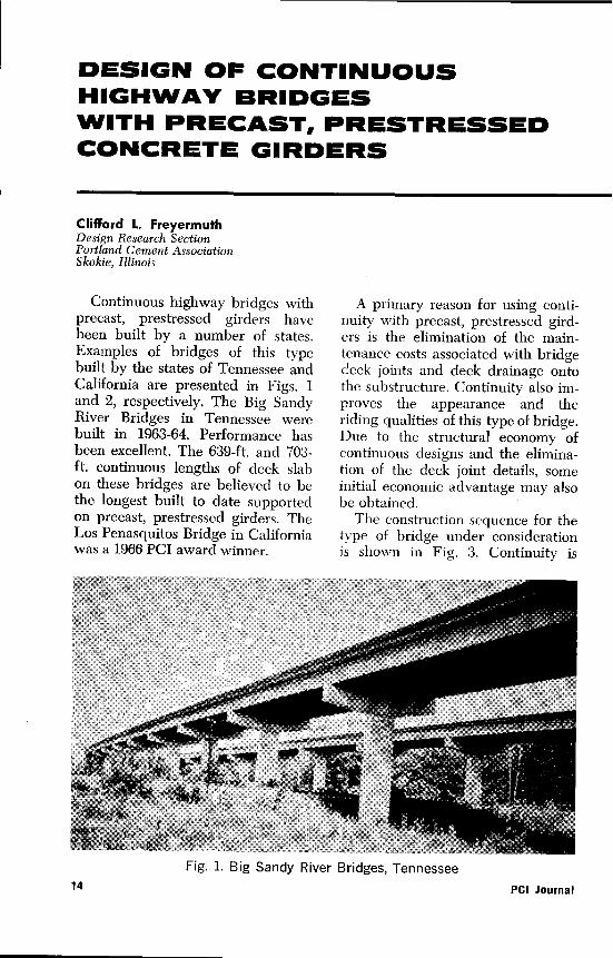
Continuous highway bridges withprecast, prestressed girders havebeen built by a number of states.Examples of bridges of this typebuilt by the states of Tennessee andCalifornia are presented in Figs. 1and 2, respectively. The Big SandyRiver Bridges in Tennessee werebuilt in 1963-64. Performance hasbeen excellent. The 639-ft. and 703-ft. continuous lengths of deck slabon these bridges are believed to bethe longest built to date supportedon precast, prestressed girders. TheLos Penasquitos Bridge in Californiawas a 1966 PCI award winner.
A primary reason for using conti-nuity with precast, prestressed gird-ers is the elimination of the main-tenance costs associated with bridgedeck joints and deck drainage ontothe substructure. Continuity also im-proves the appearance and theriding qualities of this type of bridge.Due to the structural economy ofcontinuous designs and the elimina-tion of the deck joint details, someinitial economic advantage may alsobe obtained.
The construction sequence for thetype of bridge under considerationis shown in Fig. 3. Continuity is
Fig. 1. Big Sandy River Bridges, Tennessee14 PCI Journal
To achieve continuity in a bridge using precast, prestressedsingle span units requires design considerations that alsoinclude the effects of creep and shrinkage. A complete designexample illustrates these considerations following a generaldiscussion of the principles.
achieved for live load plus impactmoments by use of non-prestressedreinforcement in the deck slab andin the diaphragms over piers. Anextensive research program on thistype of bridge was conducted by theResearch and Development Labora-tories of the Portland Cement As-sociation during 1960-61. The resultsof this research, which provide mostof the background for this publica-tion, have been made available ina series of six PCA DevelopmentDepartment Bulletins^ 1 - 6 ^. While
the above research and the ap-plications of this procedure to datehave been directed primarily to-wards bridges built with I-beams,the procedure applies equally wellto bridges with box beams, teebeams, or other available shapes.
The first portion of this report con-tains a general description of thedesign features peculiar to this typeof bridge and the background ma-terial necessary to make design cal-culations. The second portion con-sists of a design example.
Part 1. Design Procedure
PRESTRESSING REINFORCEMENTExcept for the determination of
the governing live load plus impactmoment, the design of the prestress-ing reinforcement for continuousbridges follows the well-known pro-cedure used for simple-spanbridges( 7 ). The use of continuitypermits a reduction of 5 to 15 per-cent in the required prestress forcewhen compared to simple-span de-signs. The larger reductions occurin shorter span bridges where thelive load plus impact moments area large portion of the total design
moment. Illustrative calculations fordetermining the governing live loadplus impact moments and the re-quired prestressing reinforcementare presented in the design example.
For bridges made up of a series ofequal spans, the governing live loadplus impact moment occurs at aboutthe 0.4 or 0.5 point of the end spans,with the moment at the mid-pointof interior spans being considerablyless. Therefore, in some cases it maypay to make separate designs forthe prestressing reinforcement in theinterior and exterior spans. Where
April 1969 15
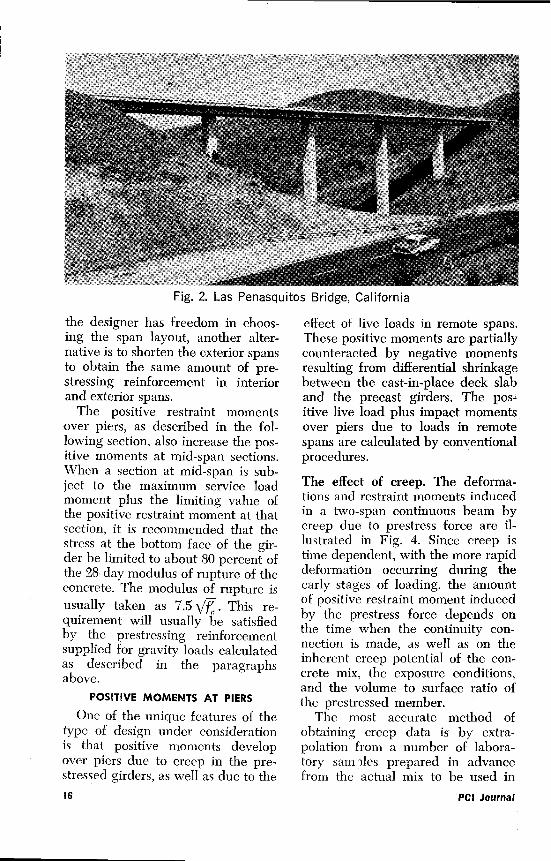
Fig. 2. Las Penasquitos Bridge, California
the designer has freedom in choos-ing the span layout, another alter-native is to shorten the exterior spansto obtain the same amount of pre-stressing reinforcement in interiorand exterior spans.
The positive restraint momentsover piers, as described in the fol-lowing section, also increase the pos-itive moments at mid-span sections.When a section at mid-span is sub-ject to the maximum service loadmoment plus the limiting value ofthe positive restraint moment at thatsection, it is recommended that thestress at the bottom face of the gir-der be limited to about 80 percent ofthe 28-day modulus of rupture of theconcrete. The modulus of rupture isusually taken as 7.5 \/f . . This re-quirement will usually be satisfiedby the prestressing reinforcementsupplied for gravity loads calculatedas described in the paragraphsabove.
POSITIVE MOMENTS AT PIERS
One of the unique features of thetype of design under considerationis that positive moments developover piers due to creep in the pre-stressed girders, as well as due to the
effect of live loads in remote spans.These positive moments are partiallycounteracted by negative momentsresulting from differential shrinkagebetween the cast-in-place deck slaband the precast girders. The pos-itive live load plus impact momentsover piers due to loads in remotespans are calculated by conventionalprocedures.
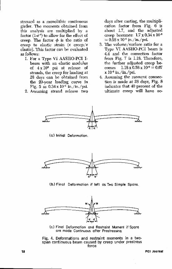
The effect of creep. The deforma-tions and restraint moments inducedin a two-span continuous beam bycreep due to prestress force are il-lustrated in Fig. 4. Since creep istime dependent, with the more rapiddeformation occurring during theearly stages of loading, the amountof positive restraint moment inducedby the prestress force depends onthe time when the continuity con-nection is made, as well as on theinherent creep potential of the con-crete mix, the exposure conditions,and the volume to surface ratio ofthe prestressed member.
The most accurate method ofobtaining creep data is by extra-polation from a number of labora-tory sam Iles prepared in advancefrom the actual mix to be used in
16 PCI Journal

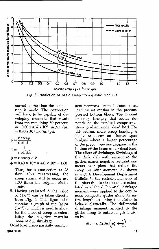
the girders. In instances wheremany beams are to be produced,it may be possible to take observa-tions on the initial beams produced,and to develop the necessary creepdata from those observations. Inmost design work, however, it willsuffice to rely on available researchdata. Such research (89) indicates thatthe basic creep value for loading at28 days can be predicted from theelastic modulus according to thecurves in Fig. 5. For design pur-poses, the 20-year creep curve canbe regarded as the ultimate creep.
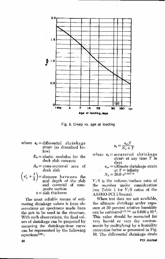
The ultimate creep value for load-ing at 28 days, from Fig. 5, mustbe adjusted to account for the agewhen the girders are prestressedand for the volume/surface ratio ofthe girders. The effects of rein-forcement on creep can usually beignored for a prestressed beam. Thevariation of creep with age at load-
ing is given by the curve in Fig.6( 8,10 ). For loading when the con-crete is one day old, for example,creep would be 1.8 times the valuefrom the 20-year curve in Fig. 5. Thevariation of creep with the volume/surface ratio is shown in Fig. 7(8,11)
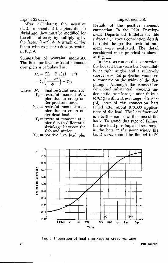
The volume/surface ratio of theAASHO-PCI I-beams, and the re-lated volume/surface ratio creep cor-rection factor, are listed in Table I.The amount of creep which will takeplace after the continuity connectionis made can be found from Fig.8( 8,12 ). For example, for a connectionmade at 28 days, about 40 percent ofthe creep strains has taken place,leaving the remaining 60 percent todevelop moments in the connection.
It has been shown( 5 ) that the ef-fects of creep under prestress anddead load can be evaluated by anelastic analysis assuming that the gir-der and slab were cast and pre-
(a.) Precast Girders Placed on Substructure.
Reinforcement
(b.) Deformed Bar Reinforcement Placed Over Pier.
See fig. II for positivemoment connection.
(c.) Deck Slab and Diaphragms Cast-in-place.
Fig. 3. Construction sequence for a two-span bridge with pre-cast, prestressed girders made continuous for live loads
April 1969 17
stressed as a monolithic continuousgirder. The moments obtained fromthis analysis are multiplied by afactor (1-e-m) to allow for the effect ofcreep. The factor 0 is the ratio ofcreep to elastic strain (e creep/eelastic). This factor can be evaluatedas follows:
1. For a Type VI AASHO-PCI I-beam with an elastic modulusof 4 x 10⁶ psi at release ofstrands, the creep for loading at28 days can be obtained fromthe 20-year loading curve inFig. 5 as 0.34 x 10 - 6 in./in./psi.
2. Assuming strand release two
days after casting, the multipli-cation factor from Fig. 6 isabout 1.7, and the adjustedcreep becomes: 1.7 x 0.34 x 10-6
= 0.58 x 10.6 in./in./psi.3. The volume/surface ratio for a
Type VI AASHO-PCI beam is4.4 and the correction factorfrom Fig. 7 is 1.18. Therefore,the further adjusted creep be-comes 1.18 x 0.58 x 10- 6 = 0.67x 10⁻⁶ in./in./psi.
4. Assuming the moment connec-tion is made at 28 days, Fig. 8indicates that 40 percent of theultimate creep will have oc-
a
(a) Initial Deformation.
a a
(b.) Final Deformation if left as Two Simple Spans.
M M
ac ¢
(c.) Final Deformation and Restraint Moment if Spansare made Continuous after Prestressina.
Fig. 4. Deformations and restraint moments in a two-span continuous beam caused by creep under prestress
force18 PCI Journal
0EIEUaC
'U■■■■■■.r■
0.1 0.2 0.3 0.4 0.5 0.6 0.7 0.8 0.9 1.0 1.1 1.2 1.3 1.4
Specific creep e. x 10-6 in./in./psi
Fig. 5. Prediction of basic creep from elastic modulus
curred at the time the connec-tion is made. The connectionwill have to be capable of de-veloping moments that resultfrom the remaining 60 percent,or, 0.60 x 0.67 x 10-6 in./in./psi= 0.40 x 10⁻⁶ in./in./psi.
e creepe elastic
E= 1E elastic
cp=e creep xE4i= 0.40x10-6x4.0x106=1.60
Thus, for a connection at 28days after prestressing, thecreep strains still to occur are1.60 times the original elasticstrain.
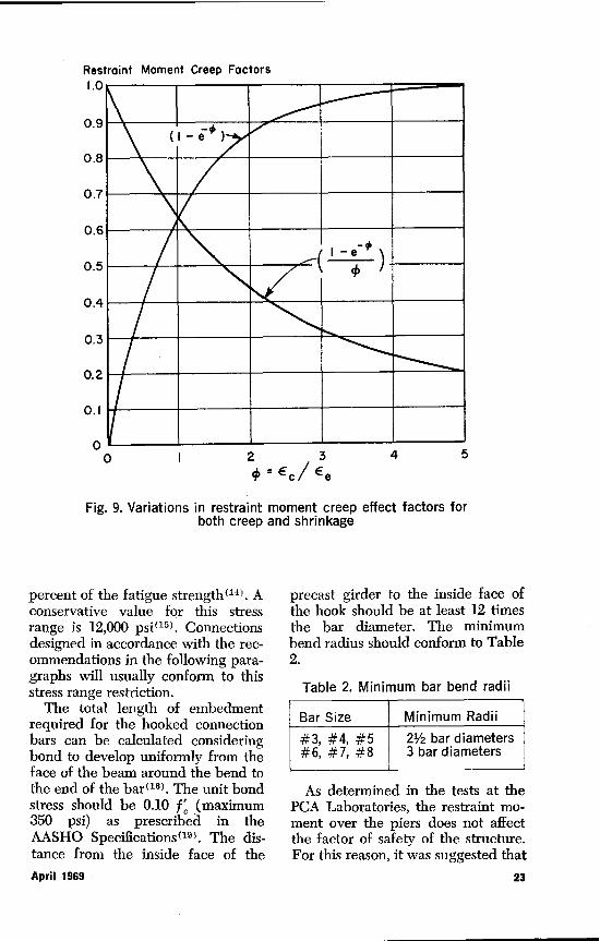
5. Having evaluated ca, the valueof (1-ej can be taken directlyfrom Fig. 9. This figure alsocontains a graph of the factor(1-e-m) 74) which is used to allowfor the effect of creep in calcu-.lating the negative restraintmoment due shrinkage.
Dead load creep partially counter-
acts prestress creep because deadload causes tension in the precom-pressed bottom fibers. The amountof creep bending that occurs de-pends on the residual compressivestress gradient under dead load. Forthis reason, more creep bending islikely to occur on shorter spanbridges where a larger percentageof the precompression remains in thebottom of the beam under dead load.The effect of shrinkage. Shrinkage ofthe deck slab with respect to thegirders causes negative restraint mo-ments over piers that reduce thecreep restraint moment. As shownin a PCA Development DepartmentBulletin( 5 >, the restraint moments atthe piers due to shrinkage are calcu-lated as if the differential shrinkagemoment were applied to the contin-uous composite girder along its en-tire length, assuming the girder tobehave elastically. The differentialshrinkage moment applied to thegirder along its entire length is giv-en by:
Mg = e3 Eb Ab ` e + t-
April 1969 19
2.0
0.
Gay 3 7 14 28 90 180 Iyr.Aye atloading,doys
Fig. 6. Creep vs. age at loading
where e8 = differential shrinkagestrain (as described be-low)
Eb = elastic modulus for thedeck slab concrete
Ab = cross-sectional area ofdeck slab
Ce2 + 2 I = distance between themid depth of the slaband centroid of com-posite section
t = slab thickness
The most reliable means of esti-mating shrinkage values is from ob-servations on specimens made fromthe mix to be used in the structure.With such observations, the final val-ues of shrinkage can be projected byassuming the shrinkage-time curvecan be represented by the followingequations (10 ) :
20
_ E8?TE8 N$ + T
where e8 = measured shrinkagestrain at any time T indays
e$.0 = ultimate shrinkage strainat T = infinity
N8 = 26.0 e°3°/5
V/S is the volume/surface ratio ofthe member under consideration(see Table 1 for V/S ratios of theAASHO-PCI I-beams).
When test data are not available,the ultimate shrinkage under expo-sure at 50 percent relative humiditycan be estimated( 12,13 ) as 0.600 x 10 -3.
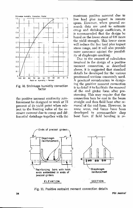
This value should be corrected forvery humid or very dry environ-ments by multiplying by a humiditycorrection factor as presented in Fig.10. The differential shrinkage strain
PCI Journal
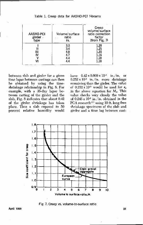
ASHO-PCI I-beams
Creepvolume/surface
AASHO-PCI Volume/surface ratio correctiongirder - ratio factortype in. (from Fig. 7)
3.0 1.28I 3.4 1.25
III 4.0 1.20IV 4.7 1.16V 4.4 1.18
VI 4.4 1.18
between slab and girder for a giventime lapse between castings can thenbe obtained by using the time-shrinkage relationship in Fig. 8. Forexample, with a 35-day lapse be-tween casting of the girder and theslab, Fig. 8 indicates that about 0.42of the girder shrinkage has takenplace. Thus a slab exposed to 50percent relative humidity would
have 0.42 x 0.600 x 10 -3 in./in. or0.252 x 10 -3 in./in. more shrinkageremaining than the girder. The valueof 0.252 x 10⁻³ would be used for e$in the above equation for M8. Thisvalue checks very closely the valueof 0.245 x 10⁻³ in./in. obtained in thePCA research( 5 ) using 10 ft. long freeshrinkage specimens of the slab andgirder and a time lag between cast-
I.8
1.7
1.6
a. 1.5
a 1.4
c I.o
1.20U•N
1.1U,
K.
0.9
■AMMEM■■■■I!,■„■■■■■■■NI■N.■■■■.■■■■OMMMM■■■IMMMOMMOMMMIII 0IE■■■■ME■E■
Volume to surface ratio, in.
Fig. 7. Creep vs. volume-to-surface ratioApril 1969 21
ings of 35 days.After calculating the negative
elastic moments at the piers due toshrinkage, they must be modified forthe effect of creep by multiplying bythe factor (1-e-')/4). A graph of thisfactor with respect to 4) is presented.in Fig. 9.
Summation of restraint moments.The final positive restraint momentover piers is calculated as:
Mr = (Y,- YDL) (1 —em)
—Y3(1—em1,+.Yra.J
where Mr = final restraint momentY, = restraint moment at a
pier due to creep un-der prestress force
YDL = restraint moment at apier due to creep un-der dead load
Y8 = restraint moment at apier due to differentialshrinkage between theslab and girder
YLL = positive live load plus
impact moment.
Details of the positive momentconnection. In the PCA Develop-ment Department Bulletin on thissubject"), various connection detailsto resist the positive restraint mo-ment were evaluated. The detailconsidered most practical is shownin Fig. 11.
In the tests run on this connection,the hooked bars were bent essential-ly at right angles and a relativelyshort horizontal projection was usedto conserve on the width of the dia-phragm. Although the connectionsdeveloped substantial moments un-der static test loads, under fatiguetesting (with a stress range of 20,000psi) most of the connection barsfailed after about 670,000 applica-tions of the load. The bars fracturedin a brittle manner at the knee of thehook. To avoid this type of failure,the live load plus impact stress rangein the bars at the point where thebend starts should be limited to 50
mU
O
m
0SC
LN
1.00.90.80.7
0.5
0.4
0.30.20.1
200.0 3yr.3 days 7 14 28 90 180 l yr. 2yr 5yr.
Time
Fig. 8. Proportion of final shrinkage or creep vs. time22 PCI Journal
Restraint Moment Creep Factors1.0
0.9
0.8
0.7
0.6
0.5 /\i0.4 / ____
0.3
0.2
0.1
2 3 4 50 °Ec/Ee
Fig. 9. Variations in restraint moment creep effect factors forboth creep and shrinkage
010
percent of the fatigue strength( 14> . Aconservative value for this stressrange is 12,000 psi( 15 >. Connectionsdesigned in accordance with the rec-ommendations in the following para-graphs will usually conform to thisstress range restriction.
The total length of embedmentrequired for the hooked connectionbars can be calculated consideringbond to develop uniformly from theface of the beam around the bend tothe end of the bar( 16 >. The unit bondstress should be 0.10 f, (maximum350 psi) as prescribed in theAASHO Specifications( 19 >. The dis-tance from the inside face of the
precast girder to the inside face ofthe hook should be at least 12 timesthe bar diameter. The minimumbend radius should conform to Table2.
Table 2. Minimum bar bend radii
Bar Size Minimum Radii
#3, #4, #5#6, #7, #8
21/2 bar diametersI 3 bar diameters
As determined in the tests at thePCA Laboratories, the restraint mo-ment over the piers does not affectthe factor of safety of the structure.For this reason, it was suggested that
April 1969 23
Shrinimge Humidity Correction Foctor1.2
1.0
0.9
0.8
0.7
0.6
0.5
0.4
0.3
0.2
0.1
0'100 90 80 70 60 50 40 30 20 10 0
Relative Humidity — Percent
Fig. 10. Shrinkage humidity correctionfactor
the positive moment continuity rein-forcement be designed to work at 75percent of its yield point when sub-ject to the limiting value of the re-straint moment due to creep and dif-ferential shrinkage together with the
Ends of precast girders
Diaphragmreinforcement
3 in n
Reinforcing bars with hookends embedded in ends ofprecast girders
ELEVATION
maximum positive moment due tolive load plus impact in remotespans. However, when general re-search data are used to estimatecreep and shrinkage coefficients, itis recommended that the design bebased on the lower stress of 0.6 timesthe yield strength. This lower stresswill reduce the live load plus impactstress range, and it will also providemore assurance against the possibil-ity of diaphragm cracking.
Due to the amount of calculationinvolved in the design of a positivemoment connection, as describedabove, it is suggested that standarddetails be developed for the variousprestressed sections commonly used.A practical consideration in design-ing the positive moment connectionis to detail it to facilitate the removalof the end girder form after pre-stressing. This may require that theconnection bars be cast in the beamstraight and then field bent after re-moval of the end form. However, insome areas, end forms have beendeveloped to accommodate shopbent bars. If field bending is re-
U.. N.n Uyrr.
reinforcement
SECTION
Fig. 11. Positive restraint moment connection details24 PCI Journal
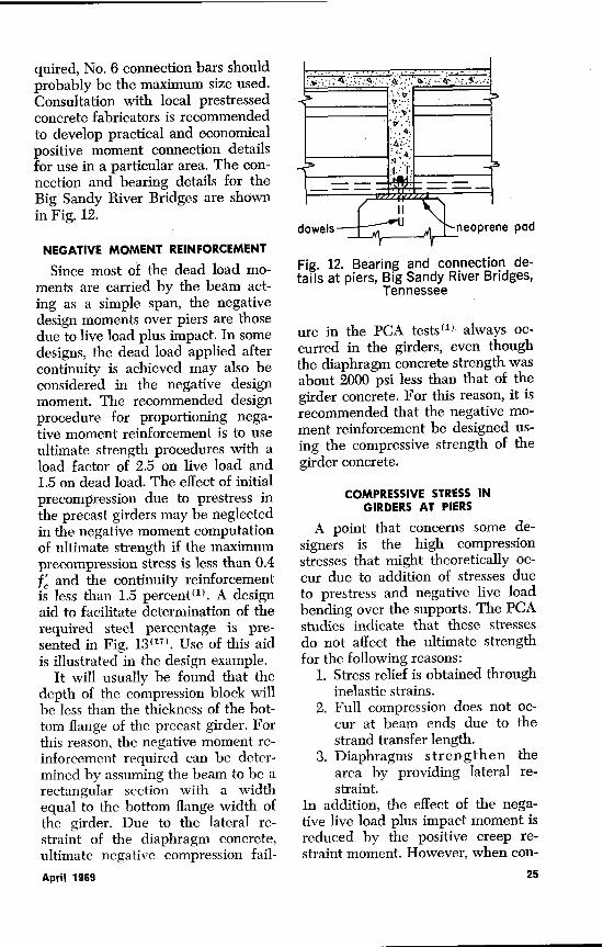
quired, No. 6 connection bars shouldprobably be the maximum size used.Consultation with local prestressedconcrete fabricators is recommendedto develop practical and economicalpositive moment connection detailsfor use in a particular area. The con-nection and bearing details for theBig Sandy River Bridges are shownin Fig. 12.
NEGATIVE MOMENT REINFORCEMENT
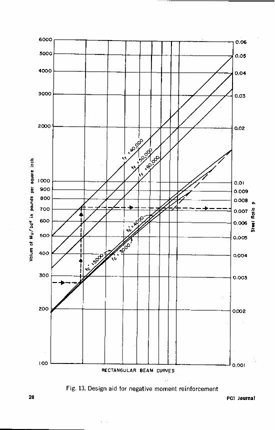
Since most of the dead load mo-ments are carried by the beam act-ing as a simple span, the negativedesign moments over piers are thosedue to live load plus impact. In somedesigns, the dead load applied aftercontinuity is achieved may also beconsidered in the negative designmoment. The recommended designprocedure for proportioning nega-tive moment reinforcement is to useultimate strength procedures with aload factor of 2.5 on live load and1.5 on dead load. The effect of initialprecompression due to prestress inthe precast girders may be neglectedin the negative moment computationof ultimate strength if the maximumprecompression stress is less than 0.4f and the continuity reinforcementis less than 1.5 percent'. A designaid to facilitate determination of therequired steel percentage is pre-sented in Fig. 13( 17 ). Use of this aidis illustrated in the design example.
It will usually be found that thedepth of the compression block willbe less than the thickness of the bot-tom flange of the precast girder. Forthis reason, the negative moment re-inforcement required can be deter-mined by assuming the beam to be arectangular section with a widthequal to the bottom flange width ofthe girder. Due to the lateral re-straint of the diaphragm concrete,ultimate negative compression fail-
Fig. 12. Bearing and connection de-tails at piers, Big Sandy River Bridges,
Tennessee
ure in the PCA tests ( ' ) always oc-curred in the girders, even thoughthe diaphragm concrete strength wasabout 2000 psi less than that of thegirder concrete. For this reason, it isrecommended that the negative mo-ment reinforcement be designed us-ing the compressive strength of thegirder concrete.
COMPRESSIVE STRESS INGIRDERS AT PIERS
A point that concerns some de-signers is the high compressionstresses that might theoretically oc-cur due to addition of stresses dueto prestress and negative live loadbending over the supports. The PCAstudies indicate that these stressesdo not affect the ultimate strengthfor the following reasons:
1. Stress relief is obtained throughinelastic strains.
2. Full compression does not oc-cur at beam ends due to thestrand transfer length.
3. Diaphragms strengthen thearea by providing lateral re-straint.
In addition, the effect of the nega-tive live load plus impact moment isreduced by the positive creep re-straint moment. However, when con-
e pad
April 1969 25
00ODQ^
_/721111/♦ ao^
1t4 O t4
00
♦
7 __
0.06
0.05
0.04
0.03
0.02
0.01D.009
).008 a
D.007 6a
).006 Z(l
).005
).004
).003
1.002
x.001
6000
500
400
300,
200(
u
H 100(90(
. 80(
70C
., 60CV
50C0
400
300
200
100RECTANGULAR BEAM CURVES
Fig. 13. Design aid for negative moment reinforcement26 PCI Journal
sidered essential, the theoretical pre-compression can be reduced byraising the strand center of gravityand/or by blanketing some of thestrands at the girder ends. Tests ofgirders with blanketed prestressingstrands have been made at the PCALaboratories (18)
SHEARThe shear tests of continuous
beams conducted at the PCA Lab-oratories ( 4 ) revealed that the presentshear provisions in the American As-sociation of State Highway Officials(AASHO) Specifications for High-
way Bridges('9 ) provide a conserva-tive estimate of the shear capacity ofa continuous beam. However, oncontinuous beams the formulas mustbe applied over the full length of thebeams rather than only over the mid-dle half of the spans, as is usually thecase for simply supported girders.
The horizontal shear stress be-tween the cast-in-place slab and theprecast girder was also investigatedat the PCA Laboratories( 4 ' 5 ). Thesetests found the horizontal shearstresses between slab and beam per-mitted by the AASHO Specificationsto be very conservative.
Part 2. Design ExampleDERIVATION OF GENERAL FORMULAS—FOUR EQUAL
CONTINUOUS SPANSThe design example is for a bridge with four equal spans of
130 ft. Prior to the detailed calculations, development of generalformulas for restraint moments due to shrinkage and creep is pre-sented. Similar developments for bridges with any number ofequal or unequal spans can be made by use of the same pro-cedure or any other consistent procedure for the analysis of in-determinant structures. The conjugate beam theory is used tocalculate the various fixed-end restraint moments. The final re-straint moments are then obtained by moment distribution.
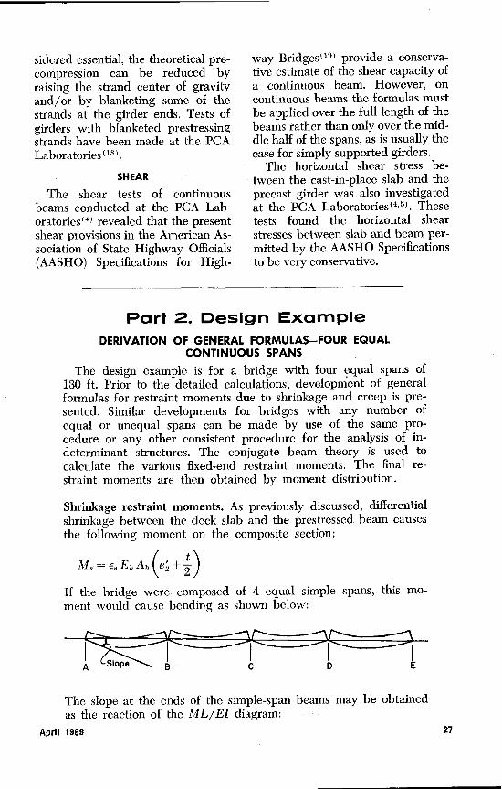
Shrinkage restraint moments. As previously discussed, differentialshrinkage between the deck slab and the prestressed beam causesthe following moment on the composite section:
MB =eg EvAv1 ez +2)If the bridge were composed of 4 equal simple spans, this mo-ment would cause bending as shown below:
The slope at the ends of the simple-span beams may be obtainedas the reaction of the ML/EI diagram:
April 1969 27
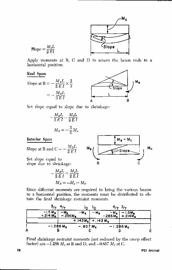
Slope = 2 EI
Apply moments at B, C and D to return the beam ends to ahorizontal position:
End Span
opeatB=— M'^L x 2 MeSlope
2 E I 3 Slope
_ MBL L
3EI A B
Set slope equal to slope due to shrinkage:
MBL_ ML3EI 2EI
MB = — 2 b13
Interior Span Me = Mc
Slope at B and C = — 2 E I MB I Slope_ Mc
Set slope equal toslope due to shrinkage: B C
_ MBL _ M8L
2E1 2E1
MB = —M8 = Mc
Since different moments are required to bring the various beamsto a horizontal position, the moments must be distributed to ob-tain the final shrinkage restraint moments.
3/7 4/, I^,, I,., 4/, 3/-,1.5M5—M$—M$
+.214 M —.286Ms— Ms —M$
—286M3— 1.5M+.214W3
+.143M5 +,143M5^ —1.286 Ms —.857M8 — 1.286 Ms
-A B C D E
Final shrinkage restraint moments (not reduced by the creep effectfactor) are —1.286 Mg at B and D, and —0.857 M$ at C.
28 PCI Journal
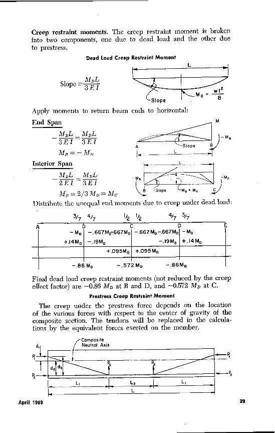
Creep restraint moments. The creep restraint moment is brokeninto two components, one due to dead load and the other dueto prestress.
Dead Load Creep Restraint MomentL
MDLSlope =3EI wl
Mo = 8Slope
Apply moments to return beam ends to horizontal:
End Span M
M8MBL _ M^,L
3EI 3EI-
p Slope
MD = — M„ L
Interior Span L
MBL — MDL -M, -M6— 2EI 3EI
B Slope Me = Me CMB=2/3M^=Mc
Distribute the unequal end moments due to creep under dead load:
3/7 4/71/2 1/24/7 3/7
D C D E
—M D —.667Mo.667Mp —.667 M D —.667Mo —MD
+.14Mp) —.19M 0—.19M0 I +.14Mp
I I +.095Mp I +.095MD I I
— .86M0—.572 MD—.86MD
Final dead load creep restraint moments (not reduced by the creepeffect factor) are —0.86 MD at B and D, and —0.572 MD at C.
Prestress Creep Restraint Moment
The creep under the prestress force depends on the locationof the various forces with respect to the center of gravity of thecomposite section. The tendons will be replaced in the calcula-tions by the equivalent forces exerted on the member.
Composited^ Neutral Axis
P
d2 d3
PZ—► -f--P2
L,
April 1969 29
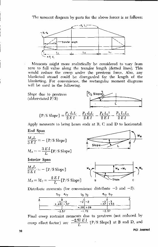
The moment diagram by parts for the above forces is as follows:
Moments might more realistically be considered to vary fromzero to full value along the transfer length (dotted lines). Thiswould reduce the creep under the prestress force. Also, anyblanketed strand could be disregarded for the length of theblanketing. For convenience, the rectangular moment diagramswill be used in the following.
Slope due to prestress [P/S Slope
(abbreviated P/S)• L
[P/S Slope] = Pi d1L — P2 d2L _ P3 Lit - P3 L,L22E1 2EI 2EI 2EI
Apply moments to bring beam ends at B; C and D to horizontal:
End Span
3 E Ie M
=— [P/S Slope] A aSlope L J
MB=-3EI [P/S Slope] r ^'
L
Interior Span
M,L = — [P/S Slope]2EI
11 j; = 11c = —2 E I [P/S Slope]
MeC Me Mc )Mc
B Slope C
Distribute moments (for convenience distribute —3 and —2):3/7 4/7 I/2 I/24/7 3/7
+.43 --2 -2 27 - i - -.57 1 +43+.28 +.28
-2.57 -1.72 -2.57Final creep restraint moments due to prestress (not reduced by
creep effect factor) are —2.57 E I [P/S Slope] at B and D, and
30 PCI Journal
-1.72 E IL [P/S Slope] at C. Recognizing that the value of [P/S
Slope] will be negative, the prestress restraint moment will thenhave a positive value.
Summing up the various restraint moments and. multiplying bythe appropriate factors, the final restraint moments due to creepand shrinkage can be calculated as:
at B and D = (-2. 5 El [P/S Slope] —0.86 M D ) (1— e-')
— (1.286 M3)(1—e'
at C = (-1.72 E I [P/S Slope] —0.572 My) (1— e -0)
—(0.857M3)(1 —e ^)
^ —
For a given value of ^, the values of (1 - e) and C1 e" * fi
)may he taken directly from Fig. 9.
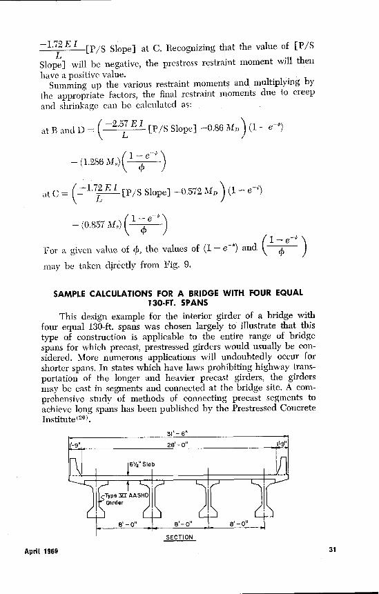
SAMPLE CALCULATIONS FOR A BRIDGE WITH FOUR EQUAL130-FT. SPANS
This design example for the interior girder of a bridge withfour equal 130-ft. spans was chosen largely to illustrate that thistype of construction is applicable to the entire range of bridgespans for which precast, prestressed girders would usually be con-sidered. More numerous applications will undoubtedly occur forshorter spans. In states which have laws prohibiting highway trans-portation of the longer and heavier precast girders, the girdersmay be cast in segments and connected at the bridge site. A com-prehensive study of methods of connecting precast segments toachieve long spans has been published by the Prestressed ConcreteInstitute (20)
JCS. I IVIM
April 1969 31
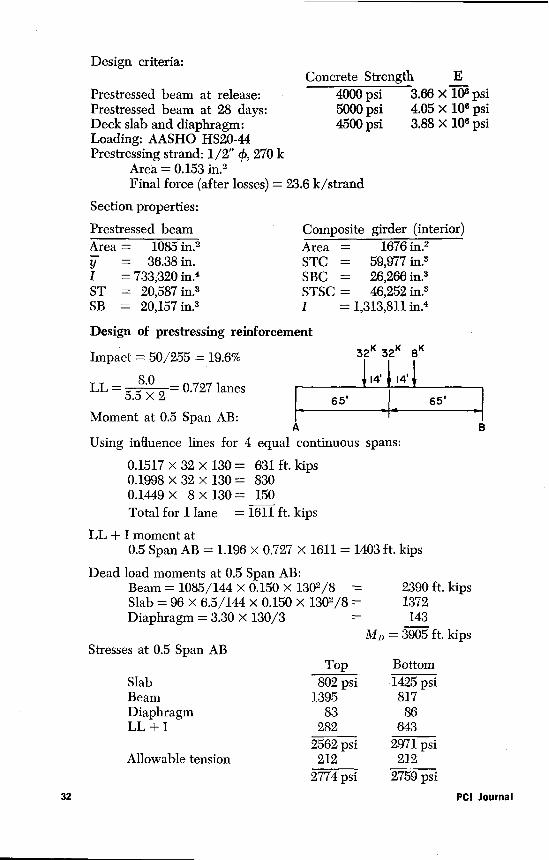
Section properties:
Prestressed beam Composite girder (interior)Area = 1085 in.2y = 36.38 in.I = 733,320 in.4ST = 20,587 in.3SB = 20,157 in.3
Area = 1676 in.2STC = 59,977 in.3SBC = 26,266 in.3STSC = 46,252 in.3I =1,313,811 in.4
Design criteria:Concrete Strength E
Prestressed beam at release: 4000 psi 3.66)< 106 psiPrestressed beam at 28 days: 5000 psi 4.05 x 10⁶ psiDeck slab and diaphragm: 4500 psi 3.88 X 10⁶ psiLoading: AASHO HS20-44Prestressing strand: 1/2" c,, 270 k
Area = 0.153 in.2Final force (after losses) = 23.6 k/strand
Design of prestressing reinforcement
Impact = 50/255 = 19.6% 32K 32K 8K
LL= 55 0 2 = 0.727 lanes114-114' I
65 65'-1Moment at 0.5 Span AB:
A BUsing influence lines for 4 equal continuous spans:
0.1517 x 32 x 130 = 631 ft. kips0.1998 x 32 x 130 = 8300.1449 x 8 x 130 = 150Total for 1 lane = 1611 ft. kips
LL + I moment at0.5 Span AB = 1.196 x 0.727 x 1611 1403 ft. kips
Dead load moments at 0.5 Span AB:Beam = 1085/144 x 0.150 x 1302/8 = 2390 ft. kipsSlab = 96 X 6.5/144 x 0.150 X 1302/8 = 1372Diaphragm = 3.30 x 130/3 = 143
MD = 3905 ft. kipsStresses at 0.5 Span AB
Top BottomSlab 802 psi 1425 psiBeam 1395 817Diaphragm 83 86LL + I 282 643
2562 psi 2971 psiAllowable tension 212 212
2774 psi 2759 psi32 PCI Journal
Assume eccentricity of strand center of gravity from bottom ofbeam = 4.70 in. Eccentricity from center of gravity:
36.38 — 4.70 = 31.68 in.
Calculate force required to give a bottom flange stress of 2759 psi:
2759 = F/1085 + F x 31.68/20.157F = 1,110,000 lb.
Strands required =1,110,000/23,600 = 47.1 strandsUse 48 - 1/2" 4) 270 k strands
Check c.g. of strands compared to assumed value:
13 at 2 = 26 raise 12 strandsat beam ends
13at4= 5213at6= 789at8= 72
48 228228/48 = 4.75 in.(close enough to assumed value)48 strands at 23.6 = 1132 kips36 strands at 23.6 = 850 kips12 strands at 23.6 = 283 kipsCheck eccentricity at girder ends for no tension under workingloads:
0 = 1132/1085 — 1132e/20,587e = 19 in. (17.38 in. from bottom)
Center of gravity of 12 harped strands must be about 55 in. fromthe bottom to provide this eccentricity. Raise center of gravity of12 strands 60 in. at ends to reduce compressive stress in bottomfibers.
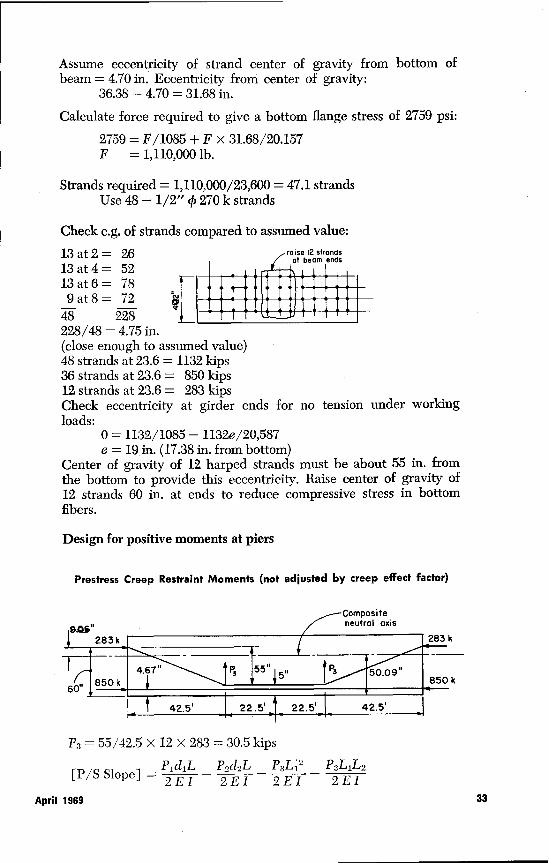
Design for positive moments at piers
Prestress Creep Restraint Moments (not adjusted by creep effect factor)
Compositeneutral axis
283k I283 k
4.67° P3 55" 5 „ jPa 50.09°60" 850 k 1 r 850 k•
42.5' 1 22.5' T 22.5' 1 42.5'
P3 = 55/42.5 x 12 x 283 = 30.5 kips
[P/S Slope] = P1 d1L _ P2d2L — P3L 1 2 — PaL1L22EI 2EI 2EI 2EI
April 1969 33
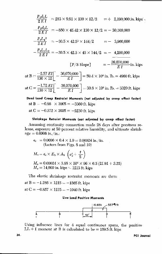
P1dAL2EI
P2d2L2EI
= 283 X 9.91 x 130 x 12/2 = + 2,190,000 in. kips
= —850 x 45.42 x 130 x 12/2 = — 30,100,000
— P3L I _ —30.5 x 42 .52 >< 144/2 = — 3,960,0002EI
— P3L,L2 = —30.5 x 42.5 x 45 x 144/2 = — 4,200,0002EI
36,070 000[P/S Slope] _ — E in. n. kips
—2.57 El _ 36,070E ,
l 000at B
130 X 12] = 59.4 x 106 in. lb: = 4960 ft. kips
2 Elat C =
13072 12 [ _ 36,07 ,000 1 = 39.8 x 106 in. lb. = 3320 ft. kips.
Dead Load Creep Restraint Moments (not adjusted by creep effect factor)
at B = —0.86 x 3905 = —3360 ft. kips
at C = —0.572 X 3905 = —2230 ft, kips
Shrinkage Retraint Moments (not adjusted by creep effect factor)
Assuming continuity connection made 28 days after prestress re-lease, exposure at 50 percent relative humidity, and ultimate shrink-age = 0.0006 in./in.:
e$ = 0,0006 x 0.4 x 1.0 = 0.00024 in./in.(factors from Figs. 8 and 10)
Mg e8 x Eb x Ab (ez + 2Ms = 0.00024 x 3.88\x 106 x 96 x 6.5 (21.91 + 3.25)M8 = 14,600 in. kips = 1215 ft. kips
The elastic shrinkage restraint moments are then:
at B = —1.286 x 1215 = —1565 ft. kips
at C = —0.857 x 1215 = —1040 ft. kips
Live Load Positive Moments
15.65k 557#/ft
A B C52'
Using influence lines for 4 equal continuous spans, the positiveLL + I moment at B is calculated to be = 169.5 ft. kips
34 PCI Journal
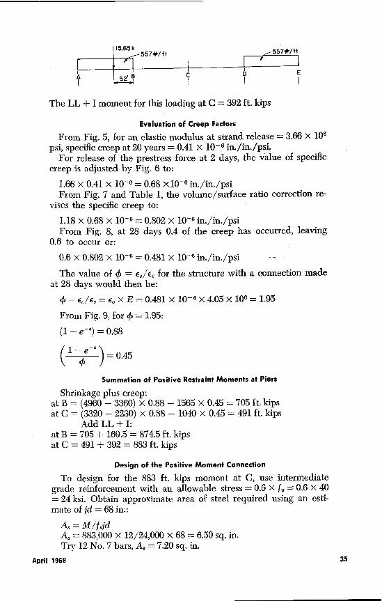
15.65 k
557*/ft557*/ ft
52 B { { {
The LL + I moment for this loading at C = 392 ft. kips
Evaluation of Creep Factors
From Fig. 5, for an elastic modulus at strand release = 3.66 X 10⁶
psi, specific creep at 20 years = 0.41 X 10⁻⁶ in./in./psi.For release of the prestress force at 2 days, the value of specific
creep is adjusted by Fig. 6 to:1.66 x 0.41 x 10-6 = 0.68 X10 -6 in./in./psiFrom Fig. 7 and Table 1, the volume/surface ratio correction re-
vises the specific creep to:
1.18 x 0.68 x 10 -E = 0.802 x 10 -s in./in./psiFrom Fig. 8, at 28 days 0.4 of the creep has occurred, leaving
0.6 to occur or:
0.6 x 0.802 x 10 -6 = 0.481 x 10', in./in./psi
The value of 0 = E,/E8 for the structure with a connection madeat 28 days would then be:
(A = E/Ee= E,xE= 0.481x10 - 6 x 4.05 x 106 = 1.95From Fig. 9, for 4) = 1.95:(1—e-')=0.88
(1—e )=0.45^ J
Summation of Positive Restraint Moments at Piers
Shrinkage plus creep:at B = (4960 — 3360) x 0.88 — 1565 x 0.45 = 705 ft. kipsat C = (3320 — 2230) x 0.88 — 1040 x 0.45 = 491 ft. kips
Add LL + I:at B = 705 + 169.5 = 874.5 ft. kipsat C = 491 + 392 = 883 ft. kips
Design of the Positive Moment Connection
To design for the 883 ft. kips moment at C, use intermediategrade reinforcement with an allowable stress = 0.6 X f, = 0.6 x 40= 24 ksi. Obtain approximate area of steel required using an esti-mate of jd = 68 in.:
A$ = M/f8jdA3 = 883,000 x 12/24,000 X 68 = 6.50 sq. in.Try 12 No. 7 bars, Ag = 7.20 sq. in.
April 1969 35
us_Uas
6'-0"
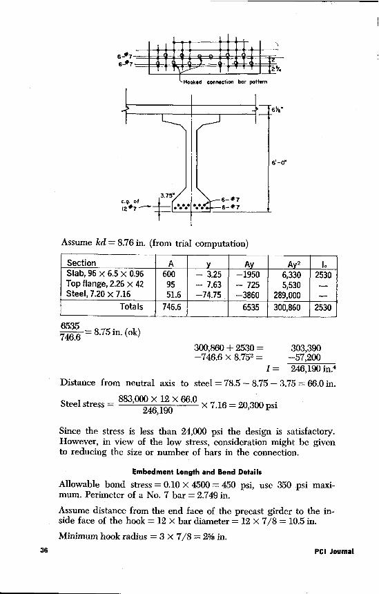
Assume kd = 8.76 in. (from trial computation)
Section A Ay A 2 toSlab, 96 x 6.5 x 0.96 600 — 3.25 —1950 6,330 2530Top flange, 2.26 x 42 95 — 7.63 — 725 5,530 -Steel, 7.20 x 7.16 51.6 —74.75 —3860 289,000 -
Totals 746.6 6535 300,860 2530
7535 = 8.75 in. (ok)46.6300,860 + 2530 = 303,390—746.6 x 8.752 = —57,200
I = 246,190 in 4Distance from neutral axis to steel = 78.5 — 8.75 — 3.75 = 66.0 in.
Steel stress 883,000 x 12 x 66.0= x 7.16 = 20,300 psi246,190
Since the stress is less than 24,000 psi the design is satisfactory.However, in view of the low stress, consideration might be givento reducing the size or number of bars in the connection.
Embedment Length and Bend Details
Allowable bond stress = 0.10 x 4500 = 450 psi, use 350 psi maxi-mum. Perimeter of a No. 7 bar = 2.749 in.
Assume distance from the end face of the precast girder to the in-side face of the hook = 12 x bar diameter = 12 x 7/8 = 10.5 in.
Minimum hook radius =3 x 7/8=2% in.36 PCI Journal
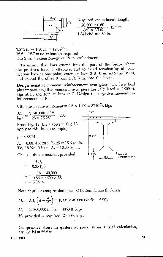
Required embedment length_ 20,300 x 0.60 = 12.2 in.
350 x 2.7491/4 bend = 4.80 in.
7.875 in. + 4.80 in. = 12.675 in.12.2 — 12.7 = no extension requiredUse 5 in. ± extension—gives 18 in. embedment
To ensure that bars extend into the part of the beam wherethe prestress force is effective, and to avoid terminating all con-nection bars at one point, extend 6 bars 3 ft. 0 in. into the beam,and extend the other 6 bars 4 ft. 6 in, into the beam.
Design negative moment reinforcement over piers. The live loadplus impact negative moments over piers are calculated as 1499 ft.
kips at B, and 1359 ft. kips at C. Design the negative moment re-inforcement at B.
Ultimate negative moment = 2.5 X 1499 = 3740 ft. kips
3.25" _ 3,740,000 X 12 — 283bd' — 28x75.252
From Fig. 13 (the arrows in Fig. 13apply to this design example):
p = 0.0074
As = 0.0074 x 28 x 75.25 = 15.6 sq. inTry 16 No. 9 bars, A3 = 16.00 sq. in.
Check ultimate moment provided:,lock
As fya_= 0.85 f b
_ 16 x 40,000a= 0.85 x 4500 x 28a = 5.98 in.
Note depth of compression block < bottom flange thickness.
Mt,= Asf,`d— 2 V= 16.00x40,000(75.25-2.99)
M,, —_ 46,300,000 in. lb. = 3850 ft. kips
M provided > required 3740 ft. kips.
Compressive stress in girders at piers. From a trial calculation,assume kd = 22.2 in.
5±
April 1969 37
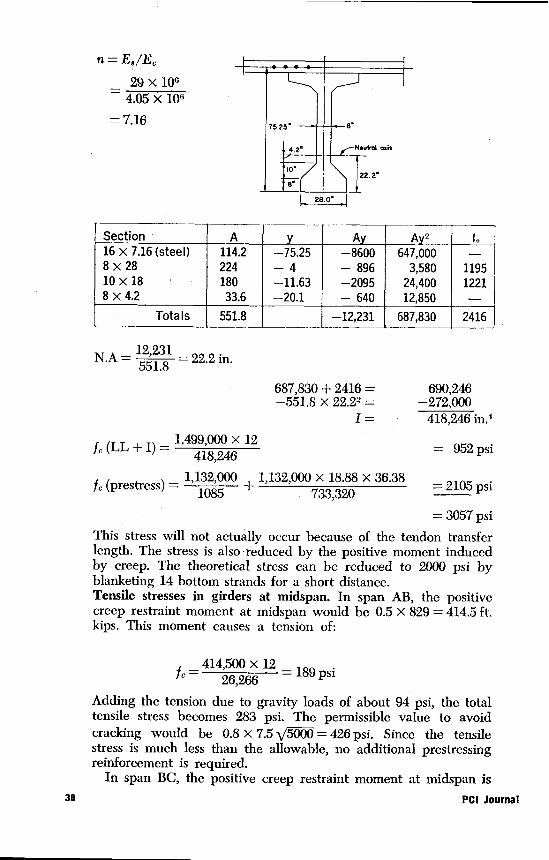
n = E8 /EC
_ 29x1064.05 x 106
= 7.16
Section A A A 2 to
16 x 7.16 (steel) 114.2 —75.25 —8600 647,0008 x 28 224 — 4 — 896 3,580 119510 x 18 180 —11.63 —2095 24,400 12218 x 4.2 33.6 —20.1 — 640 12,850
Totals 551.8 —12,231 687,830 2416
N.A = 12,231 = 22.2 in.551.8
687,830 + 2416 = 690,246
—551.8 x 22.22 _ —272,000
1= 418,246 in.4
f^ (LL + I) — 1,499,000 x 12
418,246 = 952 psi
1,132,000 1,132,000 x 18.88 X 36.38f^ (prestress) _ } 1085 + 733 320 = 2105 psi
= 3057 psiThis stress will not actually occur because of the tendon transferlength. The stress is also reduced by the positive moment inducedby creep. The theoretical stress can be reduced to 2000 psi byblanketing 14 bottom strands for a short distance.Tensile stresses in girders at midspan. In span AB, the positivecreep restraint moment at midspan would be 0.5 X 829 = 414.5 ft.kips. This moment causes a tension of:
fc ; 414,500 x 12 =189 psi26,266
Adding the tension due to gravity loads of about 94 psi, the totaltensile stress becomes 283 psi. The permissible value to avoidcracking would be 0.8 x 7.5 x/5000 = 426 psi. Since the tensilestress is much less than the allowable, no additional prestressingreinforcement is required.
In span BC, the positive creep restraint moment at midspan is38 PCI Journal
570+829 829 = 699.5 ft. ki2
ps. This causes a tensile stress of 319 psi.
Since there is no tensile stress in this span under gravity loads,this section is also satisfactory for tensile stresses due to 'creep.
REFERENCES1. Kaar, P. H., Kriz, L. B. and Hogne-
stad, E., "Precast-Prestressed ConcreteBridges 1. Pilot Tests of ContinuousBeams," Portland Cement AssociationDevelopment Department, BulletinD34.
2. Hanson, N. W., "Precast-PrestressedConcrete Bridges 2. Horizontal ShearConnections," Portland Cement Asso-ciation Development Department, Bul-letin D35.
3. Mattock, A. H. and Kaar, P. H., "Pre-cast-Prestressed Concrete Bridges 3.Further Tests of Continuous Girders,"Portland Cement Association Develop-ment Department, Bulletin D43.
4. Mattock, A. H. and Kaar, P. H., "Pre-cast-Prestressed Concrete Bridges 4.Shear Tests of Continuous Girders,"Portland Cement Association Develop-ment Department, Bulletin D45.
5. Mattock, A. H., "Precast-PrestressedConcrete Bridges 5. Creep and Shrink-age Studies," Portland Cement Asso-ciation Development Department, Bul-letin D46.a
6. Mattock, A. H. 'and Kaar, P. H., "Pre-cast-Prestressed Concrete Bridges 6.Test of Half-Scale Highway BridgeContinuous Over Two Spans," Port-land Cement Association DevelopmentDepartment, Bulletin D51.
7. Design of Highway Bridges in Pre-stressed Concrete Portland CementAssociation, Old Orchard Road, Sko-kie, :Ill.` 60076.
8. Fintel, ' Mark and Khan, Failur R.,"Effect of Column Creep and Shrink-age in Tall Structures-Prediction ofInelastic Column Shortening," Port-land Cement Association, Old; OrchardRoad, Skokie, Ill. 60076.
9. Hickey, K. B., "Creep of ConcretePredicted from Elastic Modulus Tests,"Report No. C-1242, United States De-partment of the Interior, Bureau ofReclamation, Denver, Colo., Jan. 1968.
10. "Recommendations for an International
April 1969
Code of Practice for Reinforced Con-crete," published by the AmericanConcrete Institute and the Cementand Concrete Association.
11. Hansen, T. C. and Mattock, _A. H.,"Influence of Size and Shape of Mem-ber on the Shrinkage and Creep ofConcrete," Journal of the AmericanConcrete Institute, Vol. 63, Feb. 1966,pp. 267-290.
12. Hanson, J. A., "Prestress Loss as. Af-fected by Type of Curing," Portland.Cement Association Development .De-De-partment, Bulletin D75.
13. "Design and Control of Concrete Mix-tures," Portland Cement Association,Old Orchard Road, Skokie, Ill. 60076.
14. Pfister, J. F., and Hognestad, Eivind,"High Strength Bars as Concrete Re-inforcement, Part 6. Fatigue Tests,"Portland Cement Association Develop-ment Department, Bulletin D74.
15. Hanson, John M., Burton, Kenneth • T.and Hognestad, Eivind, "Fatigue Testsof Reinforcing Bars-Effect of Defor-mation Pattern," Tentative PortlandCement Association Research and De-velopment Division Publication.
16. Hanson, N. W. and Connor, Har-old W., "Seismic Resistance of Rein-forced Concrete Beam-Column Joints,"°Portland Cement Association Develop-ment Department, Bulletin D121.
17. Ferguson, Phil M., "Simplification ofDesign by Ultimate Strength Proced-ures," Paper No. 2933, American So-ciety of Civil Engineers.
18. Kaar, P. H. and Magura, Donald D.,"Effect of Strand Blanketing on Per-formance of Pretensioned Girders,"Portland Cement Association Develop-ment Department, Bulletin D97.
19. "Standard Specifications for HighwayBridges," Ninth Edition, American As-sociation of State Highway Officials,341 National Press Building, Washing-ton, D.C. 20004.
20. "Prestressed Concrete for Long SpanBridges," 1968, Prestressed ConcreteInstitute, Chicago, Illinois.
39