Structural dynamic design of a footbridge under pedestrian loading

Design of Cable Stay Pedestrian Footbridge � SH18 Hobsonville Deviation and SH16 Brigham Creek
Extension Name: Ben Ryder, B.Eng (Hons) (Civil) Design Engineer, Connell Wagner Limited (CWDC), Auckland NZ Graduate Member of the Institution of Professional Engineers New Zealand Date of birth: 1 June 1982 (Young Author) Biography: Ben Ryder is a Civil Structures Engineer and has been working with Connell Wagner since graduation from the University of Canterbury in 2004. Ben has 4 years experience in transportation and building industry. Ben was the main designer of the Clarks Lane Footbridge during the detailed design stage. Ben was responsible for the Structural modelling and design of all structural elements of the structure including Seismic and calculation of resonant excitation from Pedestrian foot traffic and wind gusts. Ben was also responsible for co-ordination and documentation of the aspects of the design which interface with other disciplines which included. Architectural appeal, Lighting design, Storm water design, Lightning protection, Approach Ramp design and building consent application. Name: T Pang, BEng (Hons) in Civil Engineering Study Senior Engineer, Connell Wagner (CWDC), Auckland NZ Date of birth: 10th Dec 1961 Biography: Thomas Pang is a Chartered Engineer and has over 20 years of experience in development, planning, design and construction of road and railway bridges and associated infrastructures both in the United Kingdom and New Zealand. During the concept and tender phase of the project, Thomas worked closely with the Client (HEB) and the Architect (Jasmax) to develop concept designs that complied with the principles from the PR specified by TRANSIT (NZTA) and met the budgetary constraint as set by the Client, as well as observing the aspirations of both landscape and bridge architect. Thomas carried out the concept / tender design to allow the estimate being completed by the Client and provided background and technical advice during the detailed design stage of the project. Contact Details: Ben Ryder Email: [email protected] DD: 09 5236463

Design of Cable Stay Pedestrian Footbridge � SH18 Hobsonville Deviation and SH16 Brigham Creek Extension Author: Ben Ryder
Page 1 of 12
Design of Cable Stay Pedestrian Footbridge � SH18 Hobsonville Deviation and SH16 Brigham Creek
Extension Ben Ryder Design Engineer Connell Wagner Limited (CWDC), Auckland NZ
Thomas Pang, Senior Engineer, Connell Wagner (CWDC), Auckland NZ
Synopsis Architectural urban design is becoming an important aspect in the majority of roading projects as non price attributes such as the urban design are ranked highly in the assessment of tenders. This was the case for the assessment of SH18 Hobsonville deviation and SH 16 Brigham creek extension in which the urban design developed by HEB, CWDC and Jasmax was ranked highly. Architecturally designed footbridges present many challenges to the structural engineer these challenges include creating a structure that fit with in the environment while meeting the strength requirements under loadings such as crowd loading, seismic, wind loads and collision loading while staying within the required slender forms of the architectural design. These forms also create serviceability issues not usually considered in structures carrying traffic these include dynamic excitation from pedestrian foot impact load and wind loading. Durability also becomes an issue because of the more extensive use of structural steel in place of New Zealand�s
commonly used materials of prestressed and reinforced concrete. This paper presents how these challenges were calculated and overcome in the design of the Cable Stay footbridge located at Clarks lane.
Figure 1 � Architects (Jasmax) impression of the finished structure.
Introduction SH18 Hobsonville Deviation and SH16 Brigham Creek Extension Project forms part of the Upper Harbour Corridor extension for the Auckland Western Ring Route. The project is New Zealand�s largest
design and construct contract undertaken by New Zealand Transport Agency (NZTA previously Transit NZ). HEB Construction was contracted to construct the project in 2008. The Figure 2 Loaction Plan
Design of Cable Stay Pedestrian Footbridge � SH18 Hobsonville Deviation and SH16 Brigham Creek Extension Author: Ben Ryder
Page 2 of 12
project includes 6 Km of motorway a large amount of new local road diversions, five Super-T bridges with spans ranging between 23 to 35m, one Cast insitu box girder bridge on a 67 degree skew, One Cable Stay Footbridge and various MSE and Soil Nail Walls. CWDC (Connell Wagner�s Design and Construct Company) was engaged
by HEB Construction to design all Civil, Structural and Geotechnical aspects of the design following on from CWDC�s design work completed for the tender which was
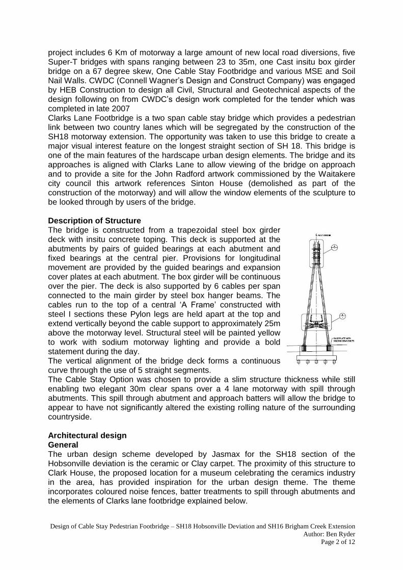
completed in late 2007 Clarks Lane Footbridge is a two span cable stay bridge which provides a pedestrian link between two country lanes which will be segregated by the construction of the SH18 motorway extension. The opportunity was taken to use this bridge to create a major visual interest feature on the longest straight section of SH 18. This bridge is one of the main features of the hardscape urban design elements. The bridge and its approaches is aligned with Clarks Lane to allow viewing of the bridge on approach and to provide a site for the John Radford artwork commissioned by the Waitakere city council this artwork references Sinton House (demolished as part of the construction of the motorway) and will allow the window elements of the sculpture to be looked through by users of the bridge. Description of Structure The bridge is constructed from a trapezoidal steel box girder deck with insitu concrete toping. This deck is supported at the abutments by pairs of guided bearings at each abutment and fixed bearings at the central pier. Provisions for longitudinal movement are provided by the guided bearings and expansion cover plates at each abutment. The box girder will be continuous over the pier. The deck is also supported by 6 cables per span connected to the main girder by steel box hanger beams. The cables run to the top of a central �A Frame� constructed with steel I sections these Pylon legs are held apart at the top and extend vertically beyond the cable support to approximately 25m above the motorway level. Structural steel will be painted yellow to work with sodium motorway lighting and provide a bold statement during the day. The vertical alignment of the bridge deck forms a continuous curve through the use of 5 straight segments. The Cable Stay Option was chosen to provide a slim structure thickness while still enabling two elegant 30m clear spans over a 4 lane motorway with spill through abutments. This spill through abutment and approach batters will allow the bridge to appear to have not significantly altered the existing rolling nature of the surrounding countryside. Architectural design General The urban design scheme developed by Jasmax for the SH18 section of the Hobsonville deviation is the ceramic or Clay carpet. The proximity of this structure to Clark House, the proposed location for a museum celebrating the ceramics industry in the area, has provided inspiration for the urban design theme. The theme incorporates coloured noise fences, batter treatments to spill through abutments and the elements of Clarks lane footbridge explained below.

Design of Cable Stay Pedestrian Footbridge � SH18 Hobsonville Deviation and SH16 Brigham Creek Extension Author: Ben Ryder
Page 3 of 12
As part of the challenge during the tender phase of the project in creating a architectural feature that would fit into the clay carpet theme, it was necessary for us to review and identify the key features of the project goals, understanding on the functionality of the bridge and approach structures as well as spatial availability over, under and adjacent to the location. During optioning stage, number of alternative structures were investigated and discounted for the following reasons, too complicated for the construction, too costly to build, too imposed, too difficult to maintain or not fitting with the architectural scheme. These rejected forms included a super tee bridge and ramps (the original sample bridge in the PR), steel box girder deck, through truss bridge, bow string arch bridge and inclined mast cable stay bridge. The preferred option was a balanced cable stay bridge. With the bridge chosen, the adjacent landscape was also extensively rearranged from the original scope to allow better harmonisation and create a pleasant experience for the end user either on or under the bridge. The Ceramic theme is incorporated into the design in three ways. The first is the bold yellow colour selected by Jasmax for the steelwork this allows the bridge to be highly visible both during the day and at night with the feature lighting enhancing the light from the yellow sodium motorway and approach ramp lighting. The second element of the clay carpet theme incorporated into the bridge is the batter treatment this uses coloured bricks to create a pattern of alternating clay colours in a wedge the width of the abutment at the top of the slope tapering to a point at the base of the batter The third element of ceramic pathway incorporated into the structure is the ceramic tiles that will be placed in a continuous strip (250mm wide) on either side of the bridge. These ceramic tiles will be decorated by local artists selected by Jasmax and Waitakere city council Artworks Two artworks will be located on and near the bridge. The first of these is the ceramic tiles that will be inlaid into the topping concrete of the bridge deck. These tiles will be decorated by an artist or group of artists to reflect this heritage theme. The artist are selected though a competition. Currently the artists Matt Mclean and Harriott Stockman are finalists in the selection process being accessed by Kim Martinengo (Waitakere City), Caroline Robinson (Jasmax) and Jeff Wells (Jasmax). The second Artwork created by John Radford this artwork references Sinton House a historical house required to be demolished as part of the construction. The sculpture is to be located near the northern abutment of the bridge it uses windows and other elements recovered from the building. The sculpture will allow the window elements of the sculpture to be looked through by users of the bridge thus giving these users a different perspective of both the bridge and the surrounding landscape. Lighting To enhance the design at night a specialised lighting scheme was designed. 12 narrow beam Cosmo Polis spotlights are mounted below each cable mount on the pier frame with elliptical beam lenses and anti glare cowls to illuminate the bridges deck. These lights offer, enough light for safe movement on the bridge, Architectural feature enhancement lighting the cables, handrails and pier frame, Minimal glare to the traffic below, minimal environmental spill lighting, Energy efficient operation over the life of the installation, Low maintenance and capital expenditure costs. Continuous LED accent lighting is located on the edge of the girder projecting onto the sloping surface of the steel girder in order to create a very low light level feature of the horizontal deck structure to travelers on the road below.

Design of Cable Stay Pedestrian Footbridge � SH18 Hobsonville Deviation and SH16 Brigham Creek Extension Author: Ben Ryder
Page 4 of 12
On the decks centre line, in ground LED coin lights at 2m centers. These lights offer to Illuminate the centre-line of the deck to separate its pathways, offer orientation to users at night and create a visual detail effect. Lighting is required for safety reasons as the bridge tower is located within 4km of the Whenuapai Airbase runway. Whilst the top of the tower is located well below the structure ceiling of the district plan it was thought prudent to provide low intensity group of omnidirectional light to alert any close aircraft movement in the area Design Life Requirements The architectural design described above required the use of steel as the main construction material. The principal�s requirements for the use of steel on this project were that it had to be designed for a 100 year design life with 40 years to first maintenance. The bridge is located near the coastline which resulted in an atmospheric classification of Marine (ISO Category 3). This highly corrosive environment and long design life required specialised coating systems to be applied to the structure (described below). Recommendations for the corrosion protection system were sought from the Heavy Engineering Research Organisation of New Zealand, paint suppliers and Connell Wagner�s internal materials experts. Steelwork. Two methods of corrosion protection were utilised to protect the main steelwork the first method was to provide a protective coating system to the exposed steelwork which comprised of a combination of: Zinc Metal spray (AS/NZS2312/TSZ200S) and high build epoxy consisting of one coat of Ultra Sheild 2000 Epoxy sealing coat followed by two colour coats of E line 379 Colour Yellow (High build epoxy) This system protects the structure against corrosion by sealing the steel from water and oxygen thus preventing the corrosion reaction this is performed by the Altex Coatings Ultra Shield 2000 epoxy and the E Line epoxy paint coatings. The Ultra shield is a low viscosity epoxy that will enter the pores left by the zinc metal spray and thus provide an effective sealant and a smoother surface for the final high build epoxy coating (E line) which will act as a further sealing layer and provide the required yellow colouring. Additionally Zinc Metal spray which with provide sacrificial cathodic protection to the steel should the sealant become damaged. The second method of corrosion protection was to remove the ingredients required to corrode. This was applied to the internal portions of the box girder this involved sealing the box by welding to prevent oxygen and water entering the box thus preventing corrosion by starving the oxidation reaction of oxygen. To prevent corrosion prior to the box being sealed during fabrication a weldable zinc rich primer was specified. The corrosion protection is to be applied to all external steel surfaces including the handrails. Cables Cables by the nature of their application are hard to inspect for the signs of corrosion and also near impossible to apply a painted system 25m above a possibly live highway. A painted system would also need to be flexible to cope with the constant flexing and deflection of the cables under service loadings. For these reasons a painted corrosion system was ruled out to protect the cables. The cable system therefore needed to not only achieve the strength and stiffness requirements of the structure but provide protection without requiring painting. Macalloy Tensotechi cable system selected provides triple corrosion protection through a combination of hot dip galvanised �Galfan� 95% zinc 5% aluminium coating combined with Tensofill Corrosion Inhibitor placed between the layers of wire strand.

Design of Cable Stay Pedestrian Footbridge � SH18 Hobsonville Deviation and SH16 Brigham Creek Extension Author: Ben Ryder
Page 5 of 12
Ground Beam (Beam elements)
Box Beam (Beam/plate element) With Fixed Bearings
Steel Pier Frame (Beam elements)
Piles Beam elements with Winkler spring
lateral supports
Stay Cable Connection positions beam elements between
Pier Pedestal (Beam element)
Figure 3 Section through central Pier
This inhibitor is a resin and zinc powder. The filler helps to prevent the entry and diffusion of moisture inside the cable and gives additional protection to the galvanised wires. A HDPE sheath will be applied full length to the outside of the cables preventing the ingress of water. The connections at the end of the cables are galfan galvanised and prepared by flaring the individual strands of the cable within the head of the connector and pouring a resin into the flared strands this seals the ends of the cable and prevents ingress of water it also means that there is no mechanical stress on the cables reducing the potential for stress induced corrosion that would be possible in traditional clamp swaging. Analysis To model the actions on the bridge effectively three-dimensional structural modelling was required. From this the moment, shear and torsion envelopes are developed for the design of each element. Dynamic analysis for pedestrian loading required the calculation of maximum accelerations of the bridge deck under service loading. The design approach incorporated 3D models using Strand 7 software the following two figures depict how the main elements of the structure were represented.
Strand 7 finite element software package was chosen because of its advanced dynamic processing ability. This ability is discussed further in the seismic and pedestrian dynamics sections below
Seismic design. The design philosophy set out in the Transit New Zealand Bridge Manual1 is similar to that of other NZ design codes when dealing with seismic design. Structures are designed to withstand the loading generated by an earthquake of a specified return period which in this case was 1000 years. Due to the complexity of the structure geometry the equivalent static force method depicted in the bridge manual cannot be used. Modal analysis was required by the code. Modal analysis was performed using Strand 7 and checked using the modal analysis feature of Space Gass. In both these analysis the natural frequencies were calculated followed by two spectral response analysis load cases these were
Guided Bearings at Abutment
Pier Ground beam and
piles
Steel Box Beam element (made up of plate elements)
Cable Elements modelled as truss elements with pin releases
Central A Frame Tower (Beam elements)
Road lanes Road lanes
Guided Bearings at Abutment
Fixed Bearings provided at pier
Figure 4 Elevation of the structure

Design of Cable Stay Pedestrian Footbridge � SH18 Hobsonville Deviation and SH16 Brigham Creek Extension Author: Ben Ryder
Page 6 of 12
transverse and longitudinal earthquakes these cases had 100% of the spectra applied in one principal direction and 30% in the other direction to account for the simultaneous occurrence of earthquake shaking in two directions. Seismic Detailing Girder restraints were an important aspect that was considered early in the design as these affected both the seismic response and the dynamic response of the bridge under pedestrian loading. The restraints at the abutment were required to deflect longitudinally for both thermal and seismic reasons. The deflection and uplift imposed on these bearings was too great to be accommodated by standard elastomeric bearings (±15mm thermal and ±75mm seismic). A secondary restraint is provided by the abutment walls, if the deflection is exceeded the girder will impact with the flat face of the end of the girder into the back wall of the abutment thus preventing further deflection. Should the lateral restraint of the bearings fail the wing walls will prevent the girder moving laterally. The restraints at the pier were required to transfer a high shear load from the longitudinal earthquake to the tower as this is the only load path available given that the abutment bearings are allowed to move for thermal reasons. The load on these bearings is unusual and has initially posed some problems for the bearing manufacturers as the lateral load is high compared to the vertical load. This is because the vertical load is transferred to the tower via the cables. The secondary mechanism should these bearings fail is that the girder will become a pendulum that can move between the abutments thus reducing the stiffness of the system and therefore the loading imposed. The cables are strong enough to carry the additional dead loading. The tower is required to resist high lateral loadings from earthquakes in both principal directions and was sized to resist all earthquake loadings. A high equilibrium torsion loading is applied to the tower cross members due to the eccentricity of the bearings to the shear centre of the cross member. This member was found to be sufficient even to resist this torque though the I section that it is constructed from is relatively weak in torsion. The base plate for the tower is required to transfer high moments from the tower legs to the concrete plinth. In order to prevent a brittle failure mechanism of bolted connection failure the connection was designed using hierarchy of strength principals. By designing the connection to resist the over strength moment from the tower leg a ductile plastic hinge will form in the base of the tower. The piles were chosen to be bottom driven 600 diameter steel tubes which will be filled with concrete and the upper portion reinforced upon completion of driving. Because of their slender nature they are not able to resist large moments in bending therefore they were arranged in two rows of five two metres apart connected by a 1m deep ground beam. This allowed the moments applied by the tower to the top of the pedestal to be resited by push pull couples between pile pairs this force was then resisted by skin friction and end bearing. Cables were chosen over stress bars due to their high strength and continuous unjointed nature. Bars have the disadvantage that if they become loaded in compression during dynamic loading (avoided by prestress to the design earthquake) they will buckle and yield this yielding will result in a permanent kink in that will most likely not be removed when the bridge returns to the self weight loading condition.

Design of Cable Stay Pedestrian Footbridge � SH18 Hobsonville Deviation and SH16 Brigham Creek Extension Author: Ben Ryder
Page 7 of 12
Geotechnical and pile design. Geotechnical investigations in the location of Clarks Lane footbridge consisted of Bore Holes, Hand augers and Cone Penetrometer testing. This testing revealed three types of soils that were present to a depth of 40m where the base rock (East coast bays formation ECBF siltstone) was found. These soils were: Tauranga Group Alluvium Clay (Atcl), A Pleistocene-aged
relatively weak silty clay (c=6-15, =23-27, =17) Tauranga Group Alluvium sand (Ats), A Pleistocene-aged loose
to medium dense silty (c=0-5, =28-30, =18) ECBF (Ew,Eu) (part of the Waitemata Group) comprising
alternating beds of weak siltstone and sandstone(Eu). located at about 35 to 40m below existing ground level the upper surface is highly to completely weathered with the consistency of residual soil. (Ew) (c=10, =30-35, =18-20 higher values represent unweathered rock)
Following these investigations it became evident that it would be uneconomic to found this structure on the bedrock and that bottom driven piles founded on the denser sand layer approximately 18m below ground level. The soil layers were modelled as Winkler springs evenly distributed along pile and lower ground beam members in the Strand 7 model. The stiffness of each spring is based on the horizontal modulus of subgrade reaction for the soil type expected to be encountered at a given location using the calculation below.
Es = drained Youngs Modulus of the soil, Epile = Youngs Modulus of the pile, Ipile = second moment of area of the pile section, s = Poissons Ratio and D = diameter of pile. Existing alluvium sands may have been locally comprised of firm to stiff silts and clays. This could have presented considerable resistance to pile penetration even under heavy driving conditions due to a state of pile hydraulicing, preventing further penetration. The designers approach to overcome this issue was to allow the excess pore water pressures developed by driving process to dissipate and then re-striking the pile to continue to drive the pile to the design depth. Testing of the piles design strength was undertaken in two ways the first was during the final stages of driving the sets were measured and the Heiley formula used to calculate the vertical load capacity of the piles. The second method was to test two piles (15% of piles) using PDA testing and capwac analysis. This PDA testing was carried out approximately one week after driving so that the final capacity of the pile could be observed without the influence of excess pore pressures. To ensure lateral and uplift capacity and to ensure that the strength observed was not due to the Hydrolicing effect a target depth was specified as well as design strength.
Tauranga group Alluvium sands (Ats)
Tauranga group Alluvium clay (Atcl)
Residual East Coast Bays formation (Ew)
East Coast Bays formation (Eu �Rock�)
Figure 5 Geological Long section extract
Design of Cable Stay Pedestrian Footbridge � SH18 Hobsonville Deviation and SH16 Brigham Creek Extension Author: Ben Ryder
Page 8 of 12
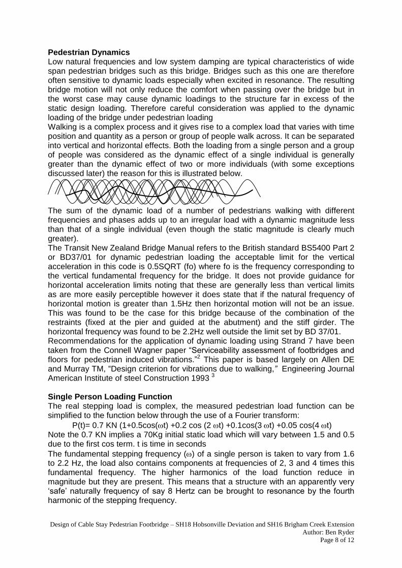
Pedestrian Dynamics Low natural frequencies and low system damping are typical characteristics of wide span pedestrian bridges such as this bridge. Bridges such as this one are therefore often sensitive to dynamic loads especially when excited in resonance. The resulting bridge motion will not only reduce the comfort when passing over the bridge but in the worst case may cause dynamic loadings to the structure far in excess of the static design loading. Therefore careful consideration was applied to the dynamic loading of the bridge under pedestrian loading Walking is a complex process and it gives rise to a complex load that varies with time position and quantity as a person or group of people walk across. It can be separated into vertical and horizontal effects. Both the loading from a single person and a group of people was considered as the dynamic effect of a single individual is generally greater than the dynamic effect of two or more individuals (with some exceptions discussed later) the reason for this is illustrated below. The sum of the dynamic load of a number of pedestrians walking with different frequencies and phases adds up to an irregular load with a dynamic magnitude less than that of a single individual (even though the static magnitude is clearly much greater). The Transit New Zealand Bridge Manual refers to the British standard BS5400 Part 2 or BD37/01 for dynamic pedestrian loading the acceptable limit for the vertical acceleration in this code is 0.5SQRT (fo) where fo is the frequency corresponding to the vertical fundamental frequency for the bridge. It does not provide guidance for horizontal acceleration limits noting that these are generally less than vertical limits as are more easily perceptible however it does state that if the natural frequency of horizontal motion is greater than 1.5Hz then horizontal motion will not be an issue. This was found to be the case for this bridge because of the combination of the restraints (fixed at the pier and guided at the abutment) and the stiff girder. The horizontal frequency was found to be 2.2Hz well outside the limit set by BD 37/01. Recommendations for the application of dynamic loading using Strand 7 have been taken from the Connell Wagner paper �Serviceability assessment of footbridges and
floors for pedestrian induced vibrations.�2 This paper is based largely on Allen DE and Murray TM, �Design criterion for vibrations due to walking,� Engineering Journal American Institute of steel Construction 1993 3
Single Person Loading Function The real stepping load is complex, the measured pedestrian load function can be simplified to the function below through the use of a Fourier transform: P(t)= 0.7 KN (1+0.5cos(t) +0.2 cos (2 t) +0.1cos(3t) +0.05 cos(4t) Note the 0.7 KN implies a 70Kg initial static load which will vary between 1.5 and 0.5 due to the first cos term. t is time in seconds The fundamental stepping frequency () of a single person is taken to vary from 1.6 to 2.2 Hz, the load also contains components at frequencies of 2, 3 and 4 times this fundamental frequency. The higher harmonics of the load function reduce in magnitude but they are present. This means that a structure with an apparently very �safe� naturally frequency of say 8 Hertz can be brought to resonance by the fourth
harmonic of the stepping frequency.

Design of Cable Stay Pedestrian Footbridge � SH18 Hobsonville Deviation and SH16 Brigham Creek Extension Author: Ben Ryder
Page 9 of 12
BD 37/01 has a forcing function of P=0.180 sin (2fot) (KN) at a velocity of vt=0.9fo (in m/s) however the application of a moving load in both time and space cannot be easily modelled therefore the approach detailed in below has been adopted noting that the above BD37/01 load corresponds to and value of 0.125 (refer below for explanation of ). Within the frequency range most likely to cause uncomfortable resonance (0-5Hz) the proposed loading below is greater. Application of Single Person Loading (Vertical) using Strand 7 The analysis method used for analysis of this bridge assumes that manual methods of analysis such as those suggested in BD 37/01 will not be used because they have been developed for simply supported structures this bridge has cable supports within the span therefore these manual methods cannot be applied but that rather a finite element analysis will be undertaken using Strand7 as described below. The system was modelled taking particular care that all masses were included as
masses rather than as loads. For bridge loading no live load was included as mass because the loading is fundamentally concerned with a single pedestrian which has negligible mass compared to that of the bridge.
The first (lowest) natural frequency of the system (that primarily involves vertical motion of the deck on which pedestrians will walk was determined using natural frequency analysis. There may be lower frequency modes that do not involve significant vertical deck motion. Such modes would not be �excited� by the
vertical loading function. A value of was chosen depending on stepping harmonic and natural frequency
(as below and adopt a loading function depending on the natural frequency of the system as:
P(t) = ( cos t) x 0.7 kN is the factor applied to determine which of the harmonic frequencies within the loading function or cos terms in the Fourier transform will be creating resonance within the structure. The critical damping ratio was taken as 0.01 as recommended by the paper Serviceability assessment of footbridges and floors for pedestrian induced vibrations. A sensitivity analysis to the damping ratio was applied as the real damping ratio is hard to determine until the structure is constructed and tested. Information has been obtained from measured values of damping for similar bridges in Sydney these measured values varied between 0.0075 and 0.0178 therefore =0.01 was deemed appropriate. Harmonic analysis was undertaken using the following parameters related to the Strand7 solver as follows: The dynamic displaced shape corresponding to the fundamental mode of
vibration was observed to identify the point of maximum dynamic displacement. A load case with a single point load located at the point of maximum dynamic
displacement as identified above with a of magnitude 0.7 kN with chosen to
1.6 2.2 3.2 4.4 4.8 6.4 6.6 8.8 (Hz)
1st harmonic 2nd harmonic 3rd harmonic 4th harmonic
= 0.5 = 0.2 = 0.1 = 0.05
Example for = 6 Hz = 0.1
Design of Cable Stay Pedestrian Footbridge � SH18 Hobsonville Deviation and SH16 Brigham Creek Extension Author: Ben Ryder
Page 10 of 12
represent the stepping harmonic excited. The strand 7 harmonic analysis automatically varies the load as 0.7cost.
The frequency range is set to ± 1 Hz to analyse frequencies either side of the natural frequency to allow graphs of the acceleration at a range of excitation frequencies to be created.
A graph for the acceleration of the same node where the load will be applied was created and exported to excel for further analysis.
From the graph of the maximum value of the acceleration is identified and reduced by the reduction factor R = 0.7 for footbridges. This factor is included to allow for the fact, �full steady- state resonance is not achieved when someone steps along the beam instead of up and down at mid-span and the walker and the person feeling the vibrations are not simultaneously at the location of maximum modal displacement� reference. Allen DE and Murray TM, �Design criterion for vibrations due to walking,� Engineering Journal American Institute of steel Construction 19932
Clarks Lane Footbridge showed first natural frequency of 1.5Hz which was just outside the range of normal walking (slower than normal walking) The analysis was showed a peak acceleration of 0.35mm s-2 this was less than the limit set out by BD37/01 of 0.63mm s-2 Multiple Pedestrian Loading Multiple pedestrian dynamic excitation is a recently discovered phenomena documented in detail with the millennium bridge in London. As such this loading application is not yet present within codes of practice however an example of best practice engineering is was therefore applied to Clarks Lane. Multiple pedestrian dynamic loading is often less than that of a single person because of the different phases and frequencies of the individual loading will cancel out and become an irregular loading that is not likely to cause resonance within the structure. This will only be true if multiple pedestrians are uncorrelated or do not walk in step. However resonance has been seen to develop suddenly on other structures in the past. There are two prerequisites for pedestrian correlation. Firstly the bridge must have either a vertical mode of vibration with a natural frequency in the range of 1.6-2.2 Hz or a horizontal mode of vibration in the range of 0.8hz to 1.1Hz (these are the frequencies of normal walking motion). The second prerequisite is that the bridge must initially start to resonate in response to uncorrelated low amplitude dynamic loading. Once resonating, people will begin to match their walking frequency in time with the bridge motion as it is more comfortable to walk in time with the motion than to walk out of step with the motion. This is a chicken and egg situation as correlation will not start to develop without resonance and resonance will not develop without some correlation. This is effectively the basis of design to avoid this phenomenon if it can be shown that a �reasonable estimate of the partially correlated dynamic load will produce a response that is below a level sufficient to encourage correlation, the correlation should not develop.� Resonance will also not develop when the bridge is loaded with greater than 0.8 people per square metre on the bridge as at a greater density than this people will not be able to walk normally without running into each other and thus having to alter step spacing and frequency. When the bridge is loaded with 5KPa (design static loading) people will be so closely packed together that they will have to shuffle to be

Design of Cable Stay Pedestrian Footbridge � SH18 Hobsonville Deviation and SH16 Brigham Creek Extension Author: Ben Ryder
Page 11 of 12
able to move, meaning that the impact from their footfall will be small and of higher frequency, thus outside resonant range. If all walkers are perfectly in step with correlation of 1.0 the correlated loading per square metre (at 0.8 people per square metre) would be simply be 0.8 times the single pedestrian loading function applied as a pressure. However this correlation is not likely to happen in practice a correlation of between 0.2 and 0.4 is probable. The lower bound value is the one of primary design interest. This may is considered to be the level of correlation that may occur without significant dynamic motion of the bridge. If analysis demonstrates that accelerations at this level of correlation are low then further correlation is unlikely. If accelerations are already high at this level then correlation is likely to increase up to the 0.4 level. Using the 0.2 correlation factor and the average value of the pedestrian loads and a crowd density of 0.8 people per square metre gives the following load functions now expressed as uniformly distributed area loads rather than point loads from a single pedestrian these will be applied in Strand 7. P(t)vertical = 36 cost Pascal Note that if the analysis predicts �unacceptable� accelerations due to the loading of equations above then further correlation may be expected and �things will get worse�.
To predict how bad things may get the upper limits of loading will be applied: P(t)vertical = 90 cost Pascal The equivalent horizontal loading functions were not applied to the bridge as the natural frequency for horizontal motion of the deck was 2.2Hz which is well outside the limit of 1.5 Hz set by BD 37/01. Application of this loading Multiple Person Loading using Strand 7 is defined below The modelling and analysis process is identical to that used for the single pedestrian loading with the following exceptions: This analysis assumes that there are 0.8 people per square metre on the bridge
and an average of 70 kg per person this is equivalent to 50 kg per square metre. This was included in the model as a well distributed set of lumped masses (6 per span).
The dynamic load cases are uniformly distributed loads. They were �shaped� to
the dynamic deflected shape of the structure. This is illustrated in the figure below representing a two span continuous beam that will have an �S� shaped first mode.
If the basic load is simply input as a downwards UDL then the �harmonic analysis�
solver will simply increase the whole lot up and down and this will not �excite� this
mode shape. If the basic load is input as shown in figure below then the harmonic analysis solver will correctly vary the load out of phase between the two spans in order to excite the fundamental mode.
Figure 6 Matching the load shape to the mode shape
Following the analysis of Clarks Lane footbridge it was found that the harmonic response to multiple pedestrian loading was found to be outside code limits for single pedestrian loading defined in BD 37/01 meaning that correlation was likely to develop. The multiple pedestrian loading and acceptance criteria are not defined in this code. The frequencies of the vertical modes affected were found to be just

Design of Cable Stay Pedestrian Footbridge � SH18 Hobsonville Deviation and SH16 Brigham Creek Extension Author: Ben Ryder
Page 12 of 12
outside the range of the normal stepping frequency therefore less likely to develop. The frequencies of the horizontal modes were found to be will outside the range that may cause horizontal excitation. The bridge is located on a country lane which accesses 10-15 lifestyle blocks therefore the likelihood of 120 people (0.8people per square meter) is considered to be very low the only likely situation would be if the nearby air force base was to run drills over the bridge. Therefore the combination of the above reduces the likelihood of the correlation developing. This correlation could result in uncomfortable passage across the bridge but will not induce loadings sufficient to damage the structure. To ensure that if in the unlikely situation that resonance should develop and becomes a problem to the users of the bridge an access hatch has been detailed to allow retrofit of the bridge with two tuned mass dampers. This access hatch was sized to allow room for a tuned mass damper with a mass of 1000Kg, the size of tuned mass dampers used in similar bridges. The specific design of these tuned mass dampers cannot be performed prior to the construction of the bridge as it is not until the actual structure is built and its natural frequencies and damping ratios are measured that the damper can be designed. This mass was added to the seismic model to check that the magnitude of the seismic forces developed with this extra mass did not exceed the calculated member capacities Due to the sensitive nature of the modeling of damping stiffness mass and the assumptions required the only true representation of how the bridge will respond will be the bridge itself, as the bridge is still under construction we do not yet know how sensitive the bridge will be to dynamic motion. CONCLUDING REMARKS Architecturally designed foot bridges such as this one presented many challenges for the structural engineer to design the structure for both strength and serviceability. These challenges can be overcome using advanced design technology such as finite analysis programmes and theories. Advanced materials such as zinc metal spray and high strength cables are also applied to overcome strength and durability issues. The result is a product that will fit into the urban design landscape and appeal to the travelling public whether they be by foot over or the motorway traffic below. REFERENCES
1. Bridge Manual, Second Edition 2003, Transit New Zealand.
2. Durack J, Serviceability assessment of footbridges and floors for pedestrian induced vibrations.
3. Allen DE and Murray TM, �Design criterion for vibrations due to walking,� Engineering Journal American Institute of steel Construction 1993
Acknowledgement We acknowledge the parties involve in the project: The project principal: NZTA , The Contractor: HEB Construction and the urban designer of the project: Jasmax Architect.
Figure 7 � Architects (Jasmax) impression of the finished structure.