Design of an Unconventional ASV for Underwater Vehicles...
8
ASNE International Conference on Launch & Recovery, November 14-15, 2012, Linthicum (MD). Design of an Unconventional ASV for Underwater Vehicles Recovery: Simulation of the motions for operations in rough seas. Stefano Brizzolara and Chryssostomos Chryssostomidis Massachusetts Institute of Technology Department of Mechanical Engineering and Sea Grant College Program, Cambridge (MA), 02139. [email protected] / [email protected] ABSTRACT Paper introduces main characteristics and particulars of an innovative design for an Unmanned Surface Vehicle to autonomously launch and recover AUVs (Autonomous Underwater Vehicles) in open sea. The USV has an unconventional SWATH hull shape and in its smaller size version, it has dedicated hangar at midship that can host one medium size AUV, completely recovered onboard. The focus of this paper is concentrated on the prediction of the steady and unsteady hydrodynamic characteristics in terms of hull resistance and motion in waves. The seakeeping prediction is made by a fully viscous 3D Unsteady Navier- Stokes solver. The predicted pitch and heave response of the USV-SWATH in relatively high regular waves, in the non- linear regime, are compared with those of an equivalent catamaran vessel and dramatic reduction in vertical motions and accelerations are found. On this good basis the paper concludes presenting a first hypothesis of the L&R system based on self-tensioning winches with hoists and belt assemblies. KEY WORDS Unmanned Surface Vehicles (USV), Small Waterplane Area Twin Hull (SWATH) vessel, AUV launch and recovery, SWATH motions in waves. 1.0 INTRODUCTION Persistent monitoring of large sea stretches, involving cooperative networks of Autonomous Underwater Vehicles (AUV) is a leading research topic in the field of underwater robotics for scientific/civilian application (water quality, oceanography) as well as for other military purposes, such for instance in security/surveillance tasks. Interesting technological advancements have been reached both in the design of the underwater vehicles with increased energy storage capabilities leading to larger endurances (Wilson and Somlyody, 2009), as well as in the autonomous intelligence. On this latter topic, it is worth mentioning the work of Bahr et al. (2009) on distributed acoustic navigation systems, with adaptive path planning in order to achieve cooperative positioning for missions of extended duration over large areas. With the same final aim, Lolla et al. (2012) propose new numerical algorithms to determine time- optimal paths of ocean vehicles in continuous dynamic flows. Huntsberger & Woodward (2011) transfer the experience made by NASA JPL on space autonomous vehicles to marine vehicles, supporting the idea of a cooperative network of surface and underwater vehicles (see the sketch of Fig. 1) to provide adaptive mission capabilities by means of a proprietary control system, as opposed to the open source software framework MOOS-IvP developed at MIT (Balasuriya et al., 2009; Benjamin et al. 2011). Fig. 1. The small USV-SWATH as the key element of an integrated cooperative AUV network The cited studies are necessary but not sufficient technologies to effectively realize a persistence system of underwater vehicles (AUVs network). The practical realization is limited, in fact, by the relatively small endurance between regular maintenance intervention to the AUVs: first of all, for their batteries recharging. This task is still delegated to manned ships equipped with special cranes (for launching and recovering of the AUVs) that usually take also care of bringing the vehicles in the specific theatre of operation. From all above considerations it is easy to derive that an Unmanned Surface Vessel (USV) specifically dedicated to support Autonomous Surface Vehicle (ASV) and capable of launching, retrieving and recharging them in place, is the real key to the realization of a true persistent sea monitoring system of AUVs. In fact, following a practical operational necessity of the NURC (NATO Undersea Research Center, La Spezia, Italy), the design and development of an innovative ASV based on an Unconventional SWATH hull
Transcript of Design of an Unconventional ASV for Underwater Vehicles...

ASNE International Conference on Launch & Recovery, November 14-15, 2012, Linthicum (MD).
Design of an Unconventional ASV for Underwater Vehicles Recovery:
Simulation of the motions for operations in rough seas.
Stefano Brizzolara and Chryssostomos Chryssostomidis
Massachusetts Institute of Technology
Department of Mechanical Engineering and Sea Grant College Program,
Cambridge (MA), 02139. [email protected] / [email protected]
ABSTRACT
Paper introduces main characteristics and particulars of an
innovative design for an Unmanned Surface Vehicle to
autonomously launch and recover AUVs (Autonomous
Underwater Vehicles) in open sea. The USV has an
unconventional SWATH hull shape and in its smaller size
version, it has dedicated hangar at midship that can host one
medium size AUV, completely recovered onboard. The
focus of this paper is concentrated on the prediction of the
steady and unsteady hydrodynamic characteristics in terms
of hull resistance and motion in waves. The seakeeping
prediction is made by a fully viscous 3D Unsteady Navier-
Stokes solver. The predicted pitch and heave response of the
USV-SWATH in relatively high regular waves, in the non-
linear regime, are compared with those of an equivalent
catamaran vessel and dramatic reduction in vertical motions
and accelerations are found. On this good basis the paper
concludes presenting a first hypothesis of the L&R system
based on self-tensioning winches with hoists and belt
assemblies.
KEY WORDS
Unmanned Surface Vehicles (USV), Small Waterplane Area
Twin Hull (SWATH) vessel, AUV launch and recovery,
SWATH motions in waves.
1.0 INTRODUCTION
Persistent monitoring of large sea stretches, involving
cooperative networks of Autonomous Underwater Vehicles
(AUV) is a leading research topic in the field of underwater
robotics for scientific/civilian application (water quality,
oceanography) as well as for other military purposes, such
for instance in security/surveillance tasks. Interesting
technological advancements have been reached both in the
design of the underwater vehicles with increased energy
storage capabilities leading to larger endurances (Wilson
and Somlyody, 2009), as well as in the autonomous
intelligence. On this latter topic, it is worth mentioning the
work of Bahr et al. (2009) on distributed acoustic navigation
systems, with adaptive path planning in order to achieve
cooperative positioning for missions of extended duration
over large areas. With the same final aim, Lolla et al. (2012)
propose new numerical algorithms to determine time-
optimal paths of ocean vehicles in continuous dynamic
flows.
Huntsberger & Woodward (2011) transfer the experience
made by NASA JPL on space autonomous vehicles to
marine vehicles, supporting the idea of a cooperative
network of surface and underwater vehicles (see the sketch
of Fig. 1) to provide adaptive mission capabilities by means
of a proprietary control system, as opposed to the open
source software framework MOOS-IvP developed at MIT
(Balasuriya et al., 2009; Benjamin et al. 2011).
Fig. 1. The small USV-SWATH as the key element of an
integrated cooperative AUV network
The cited studies are necessary but not sufficient
technologies to effectively realize a persistence system of
underwater vehicles (AUVs network). The practical
realization is limited, in fact, by the relatively small
endurance between regular maintenance intervention to the
AUVs: first of all, for their batteries recharging. This task is
still delegated to manned ships equipped with special cranes
(for launching and recovering of the AUVs) that usually
take also care of bringing the vehicles in the specific theatre
of operation.
From all above considerations it is easy to derive that an
Unmanned Surface Vessel (USV) specifically dedicated to
support Autonomous Surface Vehicle (ASV) and capable of
launching, retrieving and recharging them in place, is the
real key to the realization of a true persistent sea monitoring
system of AUVs. In fact, following a practical operational
necessity of the NURC (NATO Undersea Research Center,
La Spezia, Italy), the design and development of an
innovative ASV based on an Unconventional SWATH hull

form was initiated. The basic layout of the vessel, presented
in Fig.2 and Fig.3, is based on an unconventional optimized
hull shape for the lowest powering requirement and reduced
motions in a sea state. A summary of the vessels main
design features is published in Brizzolara et al. (2011). The
prevalent mission profile of the USV is the transportation of
medium sized AUVs used at the centre (i.e., Folaga,
Hydroid, Blue-Fin 9, etc.) from an onshore base to the
operational area being; moreover the platform itself can be
equipped with different sensors to carry out measurement
campaigns on its own. The following two sections supply
more detail information of the numerical methods used to
optimizer the hull form and about the quite unique
seakeeping performances in waves that have been recently
predicted and never presented before.
Fig. 2. USV- SWATH: view from below, hangar doors for
AUV launch and recovery are colored in gray.
2.0 VESSEL DESIGN FEATURES
This section intends to give the main features and
characteristics of the USV (paragraph 2.1) and its peculiar
hydrodynamic performance characteristics that have been
optimized and verified on extensive studies (paragraph 2.2).
More details of the optimization method for the
hydrodynamic design of the hull are given in Brizzolara &
Vernengo (2011),
2.1 General Arrangements Plans and Main Operational Characteristics
Fig. 3 shows a 3D-view of the general arrangement of the
small USV-SWATH. The underwater hulls are 6m long and
the vessel full load displacement is about 4.2t; design speed
is 12 knots. The propulsion system is diesel-electric with
two gen-sets of 25kWe in the main body (brown boxes in
Fig.3), two fast and compact DC brushless electric motors
about 20 kW in the lower hull connected through
epicycloidal gears (red cylinders) to the slow turning fixed
pitch propellers. Four battery packs are fitted in the lower
part of the struts (gray boxes). Fuel and compensation
ballast tanks are fitted in the central portion of the lower
hulls (red and yellow colored portions). They are sized to
ensure a sufficient reserve of energy to cover a range of
about 120 miles (at 12 knots) and recharge a few AUVs in a
single sortie.
The upper structure (main body) is subdivided in three
sections by two watertight bulkheads. The central section
hosts the L&R and recharging system for AUVs: in the
example of Fig. 3, a 2m long vehicle is presented inside the
docking section, in its pulled-in position. Two pairs of
stabilizer fins are fitted on each underwater hull. They are
activated by an integrated ride control system to correct the
dynamic trim and sinkage of the SWATH at high speeds
and to dampen roll, pitch, heave motions in waves.
The connection between the main body and the struts is
dismountable and the three main pieces of the vehicle are
watertight. Electric and fluid transmission between the main
body and lower hulls are realized by watertight connections.
The whole AUV can be dismounted can fitted into a
standard 40’ container to be easily transported.
Fig. 3. General Arrangement of the Small USV-SWATH, main systems are schematically represented
Patent Pending

2.1 Hull Hydrodynamic Design and Optimization
The SWATH hull form shape has been optimized to achieve
the lowest drag at cruise speed, 12 knots, corresponding to a
length based Froude number Fn0.8. The automatic
parametric optimization procedure, whose high level flow
chart is given in Fig.4, is based on a viscous-inviscid-
interaction solver, namely a free surface panel method and
thin boundary layer solver, weakly coupled through
transpiration velocities. Details of the solver and a first
example of application in a case of a larger vessel are given
in Brizzolara (2004).
Fig. 4. Highlevel flow chart of he parametric optimization
method to find the best hull form
Design constraints, such as maximum weight and main
dimensions, were assigned to guarantee the manageability
and transportability of the vehicle on land and offshore. This
resulted in rather short hulls (L=6m). So, the sufficient initial
transverse and longitudinal metacentric heights were
obtained by means of a twin canted design of the struts and
by positioning them at the forward and aft ends of the vessel,
as presented in the exemplary shape of Fig. 5.
A new hull geometry generation module has been developed
with respect to Brizzolara (2004). The new formulation is
based on a fully 3D representation of the hull and twin
canted strut surfaces with B-Spline surfaces. A new
optimization algorithm based on multi-objective,
constrained, genetic algorithms was also selected to drive the
choice of free parameters toward convergence. The main
details of this new method are given in Brizzolara &
Vernengo (2011). The parametric geometry definition uses
the least number of free parameters that permit to generate
unconventional shapes of the type presented in Fig.5. The
free parameters are the coordinates of the control vertices of
the B-spline surface that regulate the contraction of the
transverse sections in between the two relative maximum
area sections and the two curvature radii at the aft and fore
end of the hulls. A fixed aspect ratio of the elliptic transverse
sections has been used for the whole underwater body. The
geometry of the struts has been also fixed, being designed
with regards to the transverse and longitudinal stability. An
inequality constraint was given on the design displacement
with a 3% allowance margin. The value of the wave
resistance coefficients predicted for the optimum hull shape
are listed in Table 1, together with those of a conventional
shape taken from series 58 (at equal prismatic coefficient)
and of an initial guess of unconventional shape taken from
previous studies. As reported in table 1, the optimized hull
form is able to nearly halve the wave resistance of the
conventional shape. These excellent improvements were
verified by a higher fidelity CFD solver, namely a finite
volume RANSE solver (CD-Adapco, 2008) already
validated with success in case of high speed SWATH vessels
(Brizzolara & Villa, 2009). Near field wave patterns
predicted with the RANSE solver at different full scale
speeds are presented in Fig.6. the positive wave cancellation
effect at 12 knots is evident by the wave contour plots.
Fig. 5. Unconventional SWATH shapes with twin canted struts
Table 1. Wave Resistance Coefficients predicted for the
conventional, optimized and a first tentative hull shape
Optim. Original Conv. CW*103 1.915 3.336 3.533
CW % - 45.8 - 5.6 0.0
Fig. 6. Wear Field Wave Patterns generated by the best hull
form at different speeds (indicated in knots)

The total resistance evaluated by means of RANSE model in
the complete speed range of Fig. 6 has been used for the
design of the optimum propeller with a procedure similar to
that successfully used for underwater vehicles (Brizzolara &
Gaggero, 2010). The total brake power of 40kW (selected
with a 20% allowance margin) was split on two propellers of
0.7m diameter.
3.0 MOTION IN WAVES
The same finite volume RANSE solver with VoF method for
free surface calculations has been recently used to predict
the heave and pitch transfer functions of the vessel in regular
waves. In parallel, a new hybrid numerical method for
seakeeping predictions, based on 2D fully viscous
calculation of added mass and damping coefficients. The
main module successfully validated in case of conventional
monohull sections (Bonfiglio et al., 2012) is currently under
validation for catamaran and SWATHs sections. When
finished this new numerical method is expected to reduce the
calculation times, without any significant loss of accuracy
(apart from 3D effects), with respect to the 3D method used
in this study that required about 15,000 CPU-hours to
simulate all the cases needed for just a single hull type.
3.1 U-RANSE Solver and 2-DOF Model
A state of art of URANSE finite volume solver with mixture
of fluid method for free surface flows has been adapted to
the problem of the prediction of non-linear ship motion in
waves, as already tested by the author in other cases (Grasso
et al., 2010). The generic CFD solver (CD-Adapco, 2008)
can use a variety of turbulent models and solves for the
dynamic equilibrium of a floating body, whose motion is
predicted integrating the dynamic ODE of the rigid body
motion in 6 degree of freedom.
The RANS equations can be expressed, in the case of an
incompressible fluid mixture, as following:
Mmixmix STUPU Re
0
U (2)
where U is the average velocity vector field, P is the average
pressure field, μ is the dynamic viscosity, TRe is the tensor of
Reynolds stresses and SM is the vector of momentum
sources. The component of TRe is computed by means of a
realizable k-ε turbulence model that, according Boussinesq
hypothesis, implies:
ijijt
ij
i
j
j
itij
k
kxx
3
22
3
2Re
D
UU
(3)
Where μt is the turbulent viscosity, k is the turbulent kinetic
energy. To save cells close to the hull surface, a two layer
analytical wall functions suitable for ship full scale Reynolds
numbers have been adopted to extrapolate the velocity in the
prismatic layer of cells closest to the wall. According the
model a first thin linear (laminar) sub-layer close to the wall
is considered and then the extrapolation continues in the
outer region by a usual universal logarithmic law valid for
thin boundary layer. For this model to be valid, the centroid
of the first cell near needs to lie within the log-law region
where y+<100.
The RANS solver is based on a Finite-Volume method
allowing for non-structured polyhedral elements to discretize
the physical domain. The momentum and mass conservation
equations for an incompressible single virtual fluid, whose
density and viscosity properties considered as a mixture of
two uncompressible phases, given in eq. (2) are solved with
one more transport equation for a scalar function that defines
the fraction of hew liquid phase (water) present in each cell:
waterairmixwaterairmix
divt
)1(,)1(
0U (4)
This very easy model is as simple as powerful and
demonstrated its ability to find the correct shape of the free
surface between water and air in many complex non-linear
problems, including wave breaking and spray as for instance
in case of planing hulls (Brizzolara & Federici, 2010). To
solve the time-marching equations, a second order implicit
solver is used. SIMPLE method is used to conjugate
pressure field and velocity field, and the AMG (Algebraic
Multi-Grid) solver to accelerate the convergence of the
solution of (2) at each time step. In our particular case, many
iterative steps are needed to minimize the residuals in order,
in turn, to obtain an accurate prediction of ship motions in
waves. In fact, each time step, the forces acting on the hull
are calculated by integration on the wall boundary
corresponding to the hull of the tangential and normal
stresses that needs to be accurately estimated.
Fig. 7. Domain for seakeeping simulation of USV-SWATH
Steadily-progressing free surface waves can be generated
imposing an initial flow in the domain and time variant inlet
and outlet velocity fields of non-linear (up to the fifth order)

Stokes waves, according to the analytical formulation of
Fenton (1985).
A finite volume model with about 6.5M cells have been
created for the USV-SWATH, having the overall dimensions
quoted in Fig.7, in order to keep the wave reflection from
boundaries after a sufficient number of incoming waves. An
unstructured Cartesian/trimmed type mesh with progressing
refinements has been used to minimize the number of cells.
Close to the body 10 prismatic layers of cells have been used
to resolve the flow in the boundary layer and capture
eventual separation vortexes. The cell size far from body is
0.2L (L is the underwater hull length), while on the hull
surface is 0.7%L with a minimum of 0.06%L around the
area with higher curvature, automatically refined by the
surface meshing algorithm, as per Fig.8. Two anisotropic
nested cell refinements around the free surface have been
used, spanning 0.1L and 0.5L respectively. In the inner
region around the mean free surface, the mesh is composed
by prismatic cells measuring [3; 6; 0.5]% L in the
longitudinal, transversal and vertical directions, respectively.
The outer refinement region was used to adequately resolve
the wave orbital motion and it spans about twice the size of
the inner previous region.
Fig. 8. Cell refinement close to the hull and at the free surface
used for the seakeeping simulations
For the integration time step, a value smaller than T/200 was
used in all the simulation presented (T is the period of the
incoming regular wave).
3.1 Comparative Motion Prediction vs. Conventional Catamaran
The unsteady RANSE calculations in incoming bow waves
with the SWATH free to heave and pitch but stationary in
the surge motion direction have been systematically repeated
for different incoming wave lengths, having values ranging
from the same SWATH hull length L, up to three times the
SWATH length. All the regular waves had the same height,
nominally 3.5% of the SWATH hull length L, in order to be
representative of a rather extreme and non-linear condition.
To be able to compare the performance of the optimized
USV-SWATH with a possible conventional alternative, the
seakeeping CFD simulations have been repreated for a
catamaran vessel having a hard chine, deep-V hull form. The
catamaran hull has been obtained by trnaformation in
affinity from the well known Marintek catamaran
(Faltinsen, 2008, p.279). The original hull has been non
uniformly scaled with two different scale factors, one for
length and the second for beam and draft, to reach a length
of 7m and the same displacement of the SWATH. The
catamarn so obtained is presented in Fig. 9, in a snapshot of
the case with incoming wave length double the hull length
L. Fig. 10 presents a similar snapshot for the USV-SWATH
hull with an incoming wave length 2.5 times the hull length.
Fig. 9. Snapshot of the wave pattern around the Catamaran
predicted by URANSE solver (/L=2.0)
Fig. 10. Snapshot of the wave pattern around the SWATH
predicted by URANSE solver (/L=2.5)
Fig. 11. Comparison of the Heave RAO calculated for the two
equivalent vessels
A typical time hisotory of the pitch angle calculated during
the simulation for the two vessels is given in Fig.13, for the
case with /L=2.5. From the comparison of the maximum
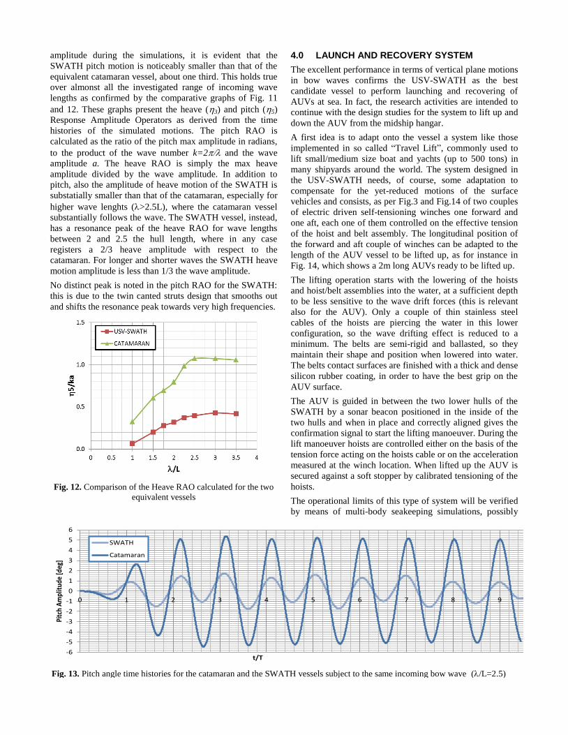
amplitude during the simulations, it is evident that the
SWATH pitch motion is noticeably smaller than that of the
equivalent catamaran vessel, about one third. This holds true
over almonst all the investigated range of incoming wave
lengths as confirmed by the comparative graphs of Fig. 11
and 12. These graphs present the heave (3) and pitch (5)
Response Amplitude Operators as derived from the time
histories of the simulated motions. The pitch RAO is
calculated as the ratio of the pitch max amplitude in radians,
to the product of the wave number k=2 and the wave
amplitude a. The heave RAO is simply the max heave
amplitude divided by the wave amplitude. In addition to
pitch, also the amplitude of heave motion of the SWATH is
substatially smaller than that of the catamaran, especially for
higher wave lenghts (>2.5L), where the catamaran vessel
substantially follows the wave. The SWATH vessel, instead,
has a resonance peak of the heave RAO for wave lengths
between 2 and 2.5 the hull length, where in any case
registers a 2/3 heave amplitude with respect to the
catamaran. For longer and shorter waves the SWATH heave
motion amplitude is less than 1/3 the wave amplitude.
No distinct peak is noted in the pitch RAO for the SWATH:
this is due to the twin canted struts design that smooths out
and shifts the resonance peak towards very high frequencies.
Fig. 12. Comparison of the Heave RAO calculated for the two
equivalent vessels
4.0 LAUNCH AND RECOVERY SYSTEM
The excellent performance in terms of vertical plane motions
in bow waves confirms the USV-SWATH as the best
candidate vessel to perform launching and recovering of
AUVs at sea. In fact, the research activities are intended to
continue with the design studies for the system to lift up and
down the AUV from the midship hangar.
A first idea is to adapt onto the vessel a system like those
implemented in so called “Travel Lift”, commonly used to
lift small/medium size boat and yachts (up to 500 tons) in
many shipyards around the world. The system designed in
the USV-SWATH needs, of course, some adaptation to
compensate for the yet-reduced motions of the surface
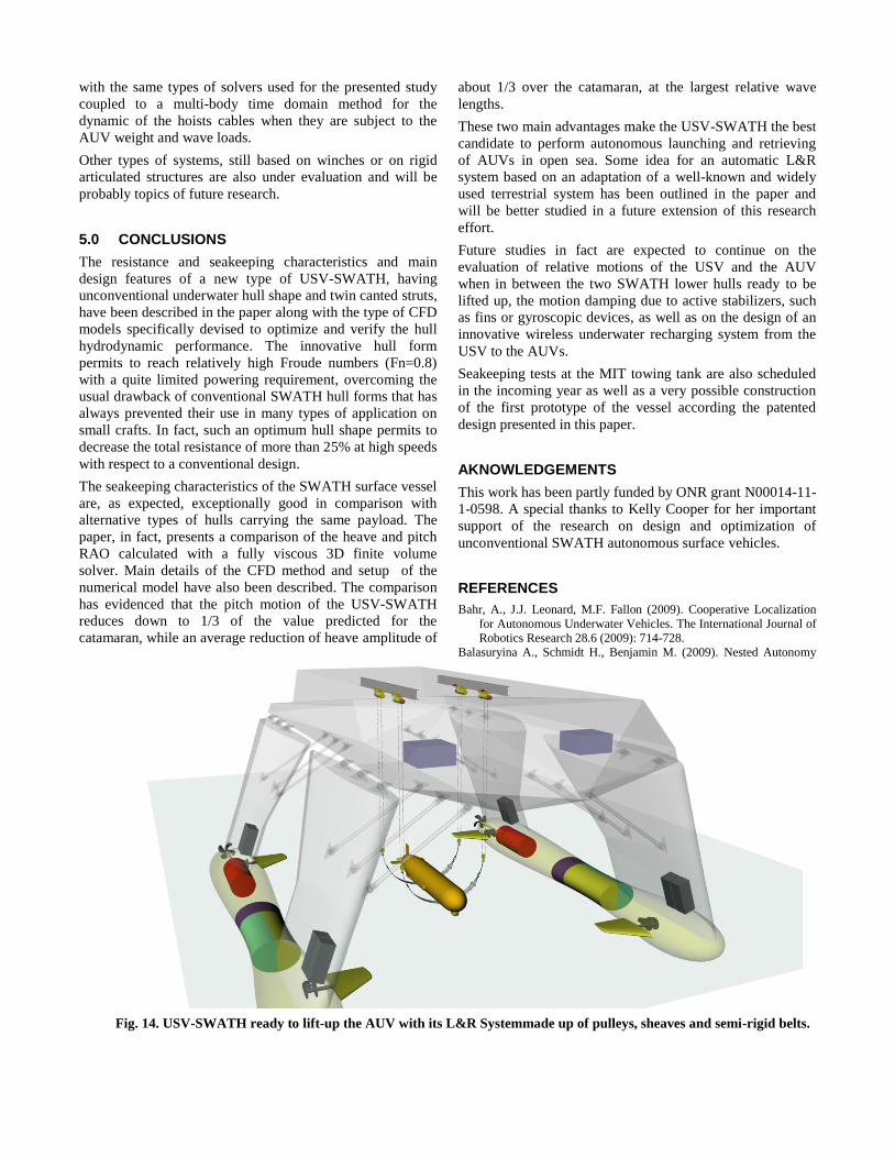
vehicles and consists, as per Fig.3 and Fig.14 of two couples
of electric driven self-tensioning winches one forward and
one aft, each one of them controlled on the effective tension
of the hoist and belt assembly. The longitudinal position of
the forward and aft couple of winches can be adapted to the
length of the AUV vessel to be lifted up, as for instance in
Fig. 14, which shows a 2m long AUVs ready to be lifted up.
The lifting operation starts with the lowering of the hoists
and hoist/belt assemblies into the water, at a sufficient depth
to be less sensitive to the wave drift forces (this is relevant
also for the AUV). Only a couple of thin stainless steel
cables of the hoists are piercing the water in this lower
configuration, so the wave drifting effect is reduced to a
minimum. The belts are semi-rigid and ballasted, so they
maintain their shape and position when lowered into water.
The belts contact surfaces are finished with a thick and dense
silicon rubber coating, in order to have the best grip on the
AUV surface.
The AUV is guided in between the two lower hulls of the
SWATH by a sonar beacon positioned in the inside of the
two hulls and when in place and correctly aligned gives the
confirmation signal to start the lifting manoeuver. During the
lift manoeuver hoists are controlled either on the basis of the
tension force acting on the hoists cable or on the acceleration
measured at the winch location. When lifted up the AUV is
secured against a soft stopper by calibrated tensioning of the
hoists.
The operational limits of this type of system will be verified
by means of multi-body seakeeping simulations, possibly
-6
-5
-4
-3
-2
-1
0
1
2
3
4
5
6
0 1 2 3 4 5 6 7 8 9 10 11 12 13 14 15 16 17 18 19 20
Pitc
h A
mpl
itud
e [d
eg]
t/T
SWATH
Catamaran
Fig. 13. Pitch angle time histories for the catamaran and the SWATH vessels subject to the same incoming bow wave (/L=2.5)
with the same types of solvers used for the presented study
coupled to a multi-body time domain method for the
dynamic of the hoists cables when they are subject to the
AUV weight and wave loads.
Other types of systems, still based on winches or on rigid
articulated structures are also under evaluation and will be
probably topics of future research.
5.0 CONCLUSIONS
The resistance and seakeeping characteristics and main
design features of a new type of USV-SWATH, having
unconventional underwater hull shape and twin canted struts,
have been described in the paper along with the type of CFD
models specifically devised to optimize and verify the hull
hydrodynamic performance. The innovative hull form
permits to reach relatively high Froude numbers (Fn=0.8)
with a quite limited powering requirement, overcoming the
usual drawback of conventional SWATH hull forms that has
always prevented their use in many types of application on
small crafts. In fact, such an optimum hull shape permits to
decrease the total resistance of more than 25% at high speeds
with respect to a conventional design.
The seakeeping characteristics of the SWATH surface vessel
are, as expected, exceptionally good in comparison with
alternative types of hulls carrying the same payload. The
paper, in fact, presents a comparison of the heave and pitch
RAO calculated with a fully viscous 3D finite volume
solver. Main details of the CFD method and setup of the
numerical model have also been described. The comparison
has evidenced that the pitch motion of the USV-SWATH
reduces down to 1/3 of the value predicted for the
catamaran, while an average reduction of heave amplitude of
about 1/3 over the catamaran, at the largest relative wave
lengths.
These two main advantages make the USV-SWATH the best
candidate to perform autonomous launching and retrieving
of AUVs in open sea. Some idea for an automatic L&R
system based on an adaptation of a well-known and widely
used terrestrial system has been outlined in the paper and
will be better studied in a future extension of this research
effort.
Future studies in fact are expected to continue on the
evaluation of relative motions of the USV and the AUV
when in between the two SWATH lower hulls ready to be
lifted up, the motion damping due to active stabilizers, such
as fins or gyroscopic devices, as well as on the design of an
innovative wireless underwater recharging system from the
USV to the AUVs.
Seakeeping tests at the MIT towing tank are also scheduled
in the incoming year as well as a very possible construction
of the first prototype of the vessel according the patented
design presented in this paper.
AKNOWLEDGEMENTS
This work has been partly funded by ONR grant N00014-11-
1-0598. A special thanks to Kelly Cooper for her important
support of the research on design and optimization of
unconventional SWATH autonomous surface vehicles.
REFERENCES
Bahr, A., J.J. Leonard, M.F. Fallon (2009). Cooperative Localization
for Autonomous Underwater Vehicles. The International Journal of
Robotics Research 28.6 (2009): 714-728.
Balasuryina A., Schmidt H., Benjamin M. (2009). Nested Autonomy
Fig. 14. USV-SWATH ready to lift-up the AUV with its L&R Systemmade up of pulleys, sheaves and semi-rigid belts.

with MOOS-IvP for Interactive Ocean Observatories. The Journal
of the Acoustical Society of America. 06/2008; 123(5):3905.
Benjamin M., Newman P., Schmidt H., Leonard J. (2011). An
Overview of MOOS-IvP and a User Guide to the IvP Helm -
Release 4.2.1. MIT CSAIL Technical Report, MIT-CSAIL-TR-
2011-037, August 2011.
Bonfiglio L. Brizzolara S., Chryssostomidis C. (2012). Added Mass
and Damping of Oscillating Bodies: a fully viscous numerical
approach. Recent Advances in Fluid Mechanics FLUIDS’12,
WSEAS editors, pp.210-215, ISBN: 978-1-61804-065-7.
Brizzolara S., Curtin T, Bovio M, Vernengo G (2011). Concept Design
and Hydrodynamic Optimization of an Innovative SWATH USV
by CFD Methods. Ocean Dynamics, vol. 61, doi: 10.1007/s10236-
011-0471-y.
Brizzolara S., Vernengo G. (2011). Automatic Optimization
Computational Method for Unconventional SWATH Ships
Resistance. Int. Journal of Mathematical Models and Methods in
Applied Sciences, vol. 5; pp. 882-889, ISSN: 1998-0140
Brizzolara S., Federici A (2010). CFD Modeling of Planning Hulls with
Partially Ventilated Bottom. The William Froude Conference:
Advances in Theoretical and Applied Hydrodynamics – Past and
Future. Portsmouth, 24-25 Nov. 2010, Royal Institution of Naval
Architects, vol. 1, ISBN/ISSN: 978-1-905040-77-3
Brizzolara S., Gaggero S. (2010.) OEX Propeller– Phase II New
Propeller Design and CFD Analysis for the OEX
Autonomous Underwater Vehicle” NURC Report NRC-
03-10, NATO Undersea Research Centre, La Spezia,
Italy. Brizzolara S. (2004) Parametric Optimization of SWAT-Hull Forms by
a Viscous-Inviscid Free Surface Method Driven by a Differential
Evolution Algorithm. Proceedings 25th Symposium on Naval
Hydrodynamics, St. John’s, Newfoundland and Labrador, vol. V,
47-64.
Huntsberger T. and Woodward G. (2011) Intelligent autonomy for
unmanned surface and underwater vehicles. In Proc. OCEANS,
pages 1–10, 2011.
Das J., Py F., Maughan T., O’Reilly T., Messié M., Ryan J., Sukhatme
G.S., Rajan K. (2012). Coordinated sampling of dynamic
oceanographic features with underwater vehicles and drifters. The
International Journal of Robotics Research, April 2012; vol. 31, 5:
626-646.
Fenton, John D. 1985. “A Fifth-Order Stokes Theory for Steady
Waves”, J. Waterway, Port, Coastal and Ocean Eng., 111 (2), pp.
216-234.
Grasso A, Villa D, Brizzolara S., Bruzzone D (2010). Nonlinear
Motions in Head Waves with a RANS and a Potential Code.
Journal of Hydrodynamics, vol. 22-5; p. 172-177, ISSN: 1001-
6058, doi: 10.1016/S1001-6058(09)60189-X
Lolla, T., M.P. Ueckermann, K. Yigit, P.Haley and P.F.J. Lermusiaux,
2012. Path Planning in Time Dependent Flow Fields using Level
Set Methods. 2012 IEEE International Conference on Robotics and
Automation.
Wilson R., Somlyody S.A. (2009). Pressure-Tolerant Lithium Polymer
Batteries. A reliable, swappable high energy density battery for
Autonomous Underwater Vehicles and Oceanographic Equipment.
Proceedings of Sea Technology Conference, 2009.