DESIGN OF AN AUTONOMOUS TELEOPERATED CARGO …
97
1 7 J 2 DESIGN OF AN AUTONOMOUS TELEOPERATED CARGO TRANSPORTING VEHICLE FOR LUNAR BASE OPERATIONS Submitted to: Mr. James A. Aliberti NATIONAL AERONAUTICS AND SPACE ADMINISTRATION Kennedy Space Center, Florida Prepared by: James Holt, Team Leader Tom Lao Nkoy Monali Mechanical Engineering Department THE UNIVERSITY OF TEXAS AT AUSTIN Austin, Texas Fall I989 ( _A"....... ;_-_ _-1 "_" .. ' _., ) i _:il .,' :'-"i- &'J _.LJTUNUMLJIJ.% C_,Ck 1.3I ,-. _1 2_-r UDC] ,_q
Transcript of DESIGN OF AN AUTONOMOUS TELEOPERATED CARGO …
17
J2
DESIGN OF AN AUTONOMOUS
TELEOPERATED CARGO
TRANSPORTING VEHICLE FOR
LUNAR BASE OPERATIONS
Submitted to:
Mr. James A. Aliberti
NATIONAL AERONAUTICS AND SPACE ADMINISTRATION
Kennedy Space Center, Florida
Prepared by:
James Holt, Team Leader
Tom Lao
Nkoy Monali
Mechanical Engineering Department
THE UNIVERSITY OF TEXAS AT AUSTIN
Austin, Texas
Fall I989
( _A".......;_-_ _-1 "_" .. ' _.,) i _:il .,' :'-"i- &'J _.LJTUNUMLJIJ.%
C_,Ck 1.3I
,-. _1 2_-r
UDC] ,_q
MECHANICAL ENGINEERING DESIGN PROJECTS PROGRAM
THE UNIVERSITY OF TEXAS AT AUSTIN
ETC 4.102"Austin, Texas 78712- 1063" (5 i 2) 471-3 900
November 15, 1989
°
James A. Aliberti
Manager of Research Programs
Mail Stop PT-PMO
Kennedy Space Center, Florida 32899
Dear Mr. Aliberti:
Attached is our final report entitled "Design of an Autonomous,
Teleoperated Cargo Transporting Vehicle for Lunar Base Operations".
This report contains a description of the cargo transporting vehicle
and its operation, detailed analyses of several subsystems, a
comparison to the Lunar Roving Vehicle, and our recommendations
for future design and development of the vehicle.
The team is looking forward to seeing you at the final design
presentation. The presentation is scheduled for Tuesday, December
5, 1989, at 10:00 a.m. in the Engineering Teaching Center II, Room
4.110, on the campus of The University of Texas at Austin. A catered
luncheon will follow the presentation at noon.
Sincerely,
James Holt, Team Leader
/._, "_ _7_ - _/._
Tom Lao
• _jNkoy Monali
ACKNOWLEDGEMENTS
The team members would like to thank the National
Aeronautics and Space Administration (NASA), the Universities Space
Research Association (USRA), and Mr. James A. Aliberti from the
Kennedy Space Center for sponsoring this project.
Special thanks goes to Dr. Kris Wood, our faculty advisor, for his
technical and editorial assistance, and for showing confidence in the
team's capabilities throughout the project.
Thanks also to Professor Lou Torfason for his technical
assistance in the design of the track and wheel assemblies.
Thanks to Dr. Bob Freeman for his help in designing the robotic
arms.
The team is grateful to Mr. Brian H. Wilcox of the Robotics and
Teleoperations Research Group at the Jet Propulsion Laboratory in
Pasaden_i, California, for his help in teleoperation systems.
The team would like to express their appreciation to Dr. Steven
P. Nichols for coordinating the ME 366K Senior Design Projects
Program and the lectures throughout the semester.
Thanks are extended to Mr. Wendell Dean for his technical
advice in graphical communication.
The team would also like to thank Mr. Richard B. Connell,
Teaching Assistant, and Mr. Bert Herigstad, Design Projects
Administration Assistant, for their technical and administrative
assistance throughout the project.
ii
L
ABSTRACT
DESIGN OF AN AUTONOMOUS, TELEOPERATED CARGO
TRANSPORTING VEHICLE FOR LUNAR BASE OPERATIONS
At the turn of the century, the National Aeronautics and Space
Administration (NASA) plans to begin construction of a lunar base.
The base will likely consist of developed areas (i.e. habitation,
laboratory, landing and launching sites, power plant) separated from
each other due to safety considerations. The team has designed the
Self-Repositioning Track Vehicle (SRTV) to transport cargo between
these base facilities. The SRTV operates by using two robotic arms to
raise and position segments of track upon which the vehicle travels.
The SRTV utilizes the Semiautonomous Mobility (SAM) method of
teleoperation, actuator-controlled interlocking track sections, two
robotic arms each with five degrees of freedom, and these materials:
titanium for structural members, aluminum for shell members, with
the possibility of using light-weight, high-strength composites.
KEY WORDS: LUNAR, TRANSPORTATION, TELEOPERATION, ROBOTICS
James Holt, Team Leader
/ g,J
Tom Lao
.... -_Nko3) Monali "
iii
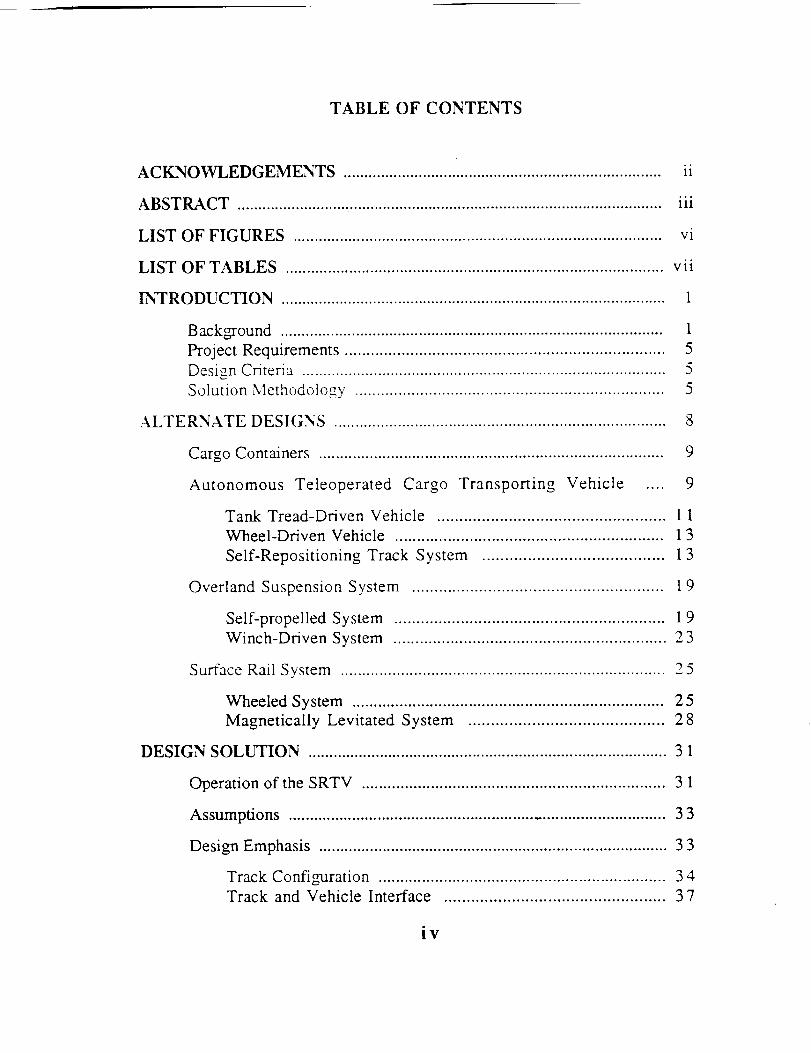
TABLE OF CONTENTS
ACI_NOWLEDGEMENTS ............................................................................ ii
ABSTRACT ...................................................................................................... iii
LIST OF FIGURES ....................................................................................... vi
LIST OF TABLES ......................................................................................... vii
INTRODUCTION ............................................................................................ 1
Background ........................................................................................... 1
Project Requirements ......................................................................... 5
Design Criteria ...................................................................................... 5
Solution Methodology ....................................................................... 5
ALTERNATE DESIGNS .............................................................................. 8
Cargo Containers ................................................................................. 9
Autonomous Teleoperated Cargo Transporting Vehicle .... 9
Tank Tread-Driven Vehicle ................................................... 11
Wheel-Driven Vehicle ............................................................. 13
Self-Repositioning Track System ........................................ 13
Overland Suspension System ........................................................ ! 9
Self-propelled System ............................................................. 19
Winch-Driven System .............................................................. 23
Surface Rail System ........................................................................... 25
Wheeled System ........................................................................ 25
Magnetically Levitated System ........................................... 28
DESIGN SOLUTION ..................................................................................... 31
Operation of the SRTV ...................................................................... 31
Assumptions ........................................................................................ 33
Design Emphasis .................................................................................. 33
Track Config-uration .................................................................. 34Track and Vehicle Interface ................................................. 37
iv
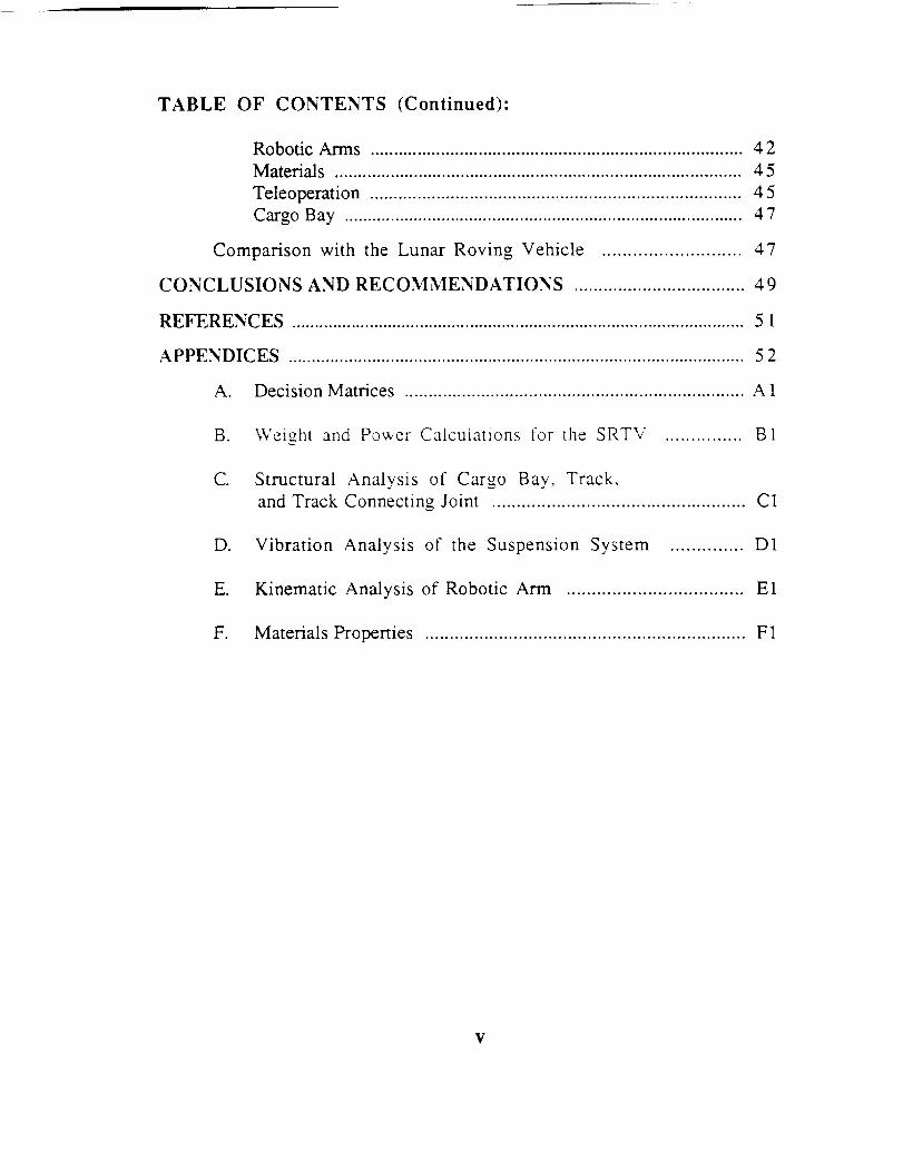
TABLE OF CONTENTS (Continued):
Robotic Arms ............................................................................... 42
Materials ....................................................................................... 45
Teleoperation .............................................................................. 45
Cargo Bay ...................................................................................... 47
Comparison with the Lunar Roving Vehicle ........................... 47
CONCLUSIONS AND RECOMMENDATIONS ................................... 49
REFERENCES ................................................................................................... 51
APPENDICES .................................................................................................. 52
A. Decision Matrices ....................................................................... A 1
B. Weight and Power Calculations for the SRTV ............... B1
C. Structural Analysis of Cargo Bay, Track,
and Track Connecting Joint ................................................... C1
D. Vibration Analysis of the Suspension System .............. D1
E. Kinematic Analysis of Robotic Arm ................................... E1
F. Materials Properties ................................................................. F1
V
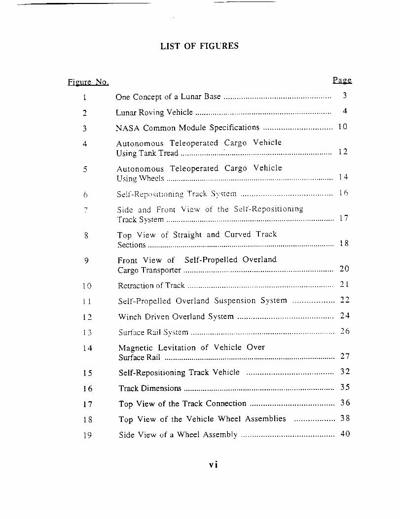
LIST OF FIGURES
Figure No.
1
2
3
4
5
6
7
10
11
12
13
14
15
16
17
18
19
One Concept of a Lunar Base .................................................
Lunar Roving Vehicle ...............................................................
Eaz_e_
3
4
NASA Common Module Specifications ............................... 10
Autonomous Teleoperated Cargo Vehicle
Using Tank Tread .................... _.................................................. 1 2
Autonomous Teleoperated Cargo Vehicle
Using Wheels ................................................................................ l 4
Selt-Repositioning Track System ......................................... 16
Side and Front View of the Self-Repositioning
Track System ................................................................................ 1 7
Top View of Straight and Curved Track
Sections ........................................................................................... 18
Front View of Self-Propelled Overland
Cargo Transporter ...................................................................... 20
Retraction of Track .................................................................... 21
Self-Propelled Overland Suspension System .................. 22
Winch Driven Overland System ........................................... 24
Surface Rail System ................................................................... 26
Magnetic Levitation of Vehicle Over
Surface Rail .................................................................................. 27
Self-Repositioning Track Vehicle ....................................... 32
Track Dimensions ....................................................................... 35
Top View of the Track Connection ...................................... 36
Top View of the Vehicle Wheel Assemblies .................. 38
Side View of a Wheel Assembly .......................................... 40
vi
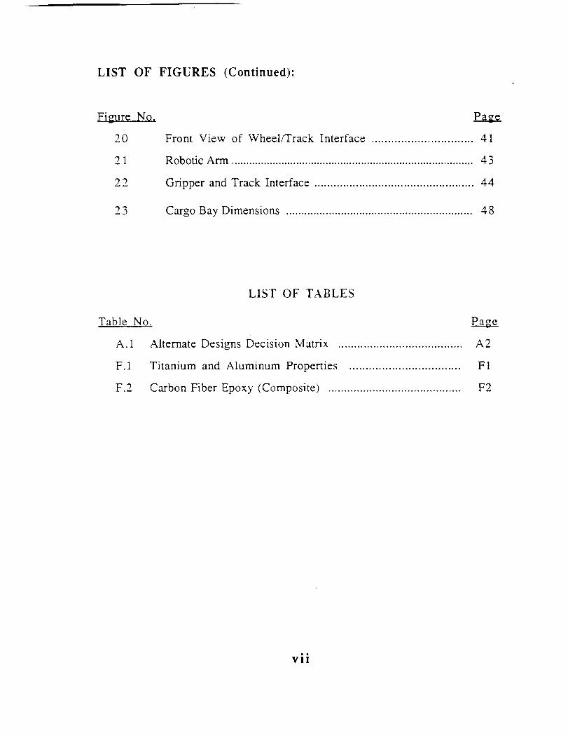
LIST OF FIGURES (Continued):
Figure No.
20
21
22
23
Front View of Wheel/Track Interface ............................... 41
Robotic Arm .................................................................................. 43
Gripper and Track Interface .................................................. 44
Cargo Bay Dimensions ............................................................. 48
LIST OF TABLES
Table NO,
A.1
F.1
F.2
Alternate Designs Decision Matrix ....................................... A2
Titanium and Aluminum Properties .................................. F1
Carbon Fiber Epoxy (Composite) .......................................... F2
vii
INTRODUCTION
The United States National Aeronautics and Space
Administration (NASA) is a government agency established in 1958
to coordinate and conduct space research and exploration. NASA has
contracted the Universities Space Research Association (USRA) to
establish a partnership between NASA engineers and university
students and faculty for the education in, and development of space
science and technology'. The USRA is a private consortium organized
in 1969 by the National Academy of Sciences to promote interaction
between universities and corporate research institutions.
The NASA/USRA Advanced Design Program integrates selected
NASA space/aeronautics design projects into universities' senior
design courses. The objectives of the Advanced Design Program are,
to enhance student's design experiences and to provide NASA with
new design ideas from bright young students. The team has
designed an autonomous, teteoperated cargo transporting vehicle for
NASA's proposed lunar base. The remainder of this report describes
the alternative systems available, the design solution, and
recommendations for this design.
BACKGROUND
NASA and its space system contractors and consultants are
designing a manned lunar base with construction set to begin early
in the next century. The reasons for establishing a lunar base
2
involve science, resource, and technology development
considerations. The primary commercial benefits of a lunar base lie
in the extraction of oxygen from the lunar soil. Lunar oxygen
(LUNOX) is an important element for maintenance of a space station.
support of a lunar base, and further interplanetary missions as it
will be used in life support, propulsion, and water production.
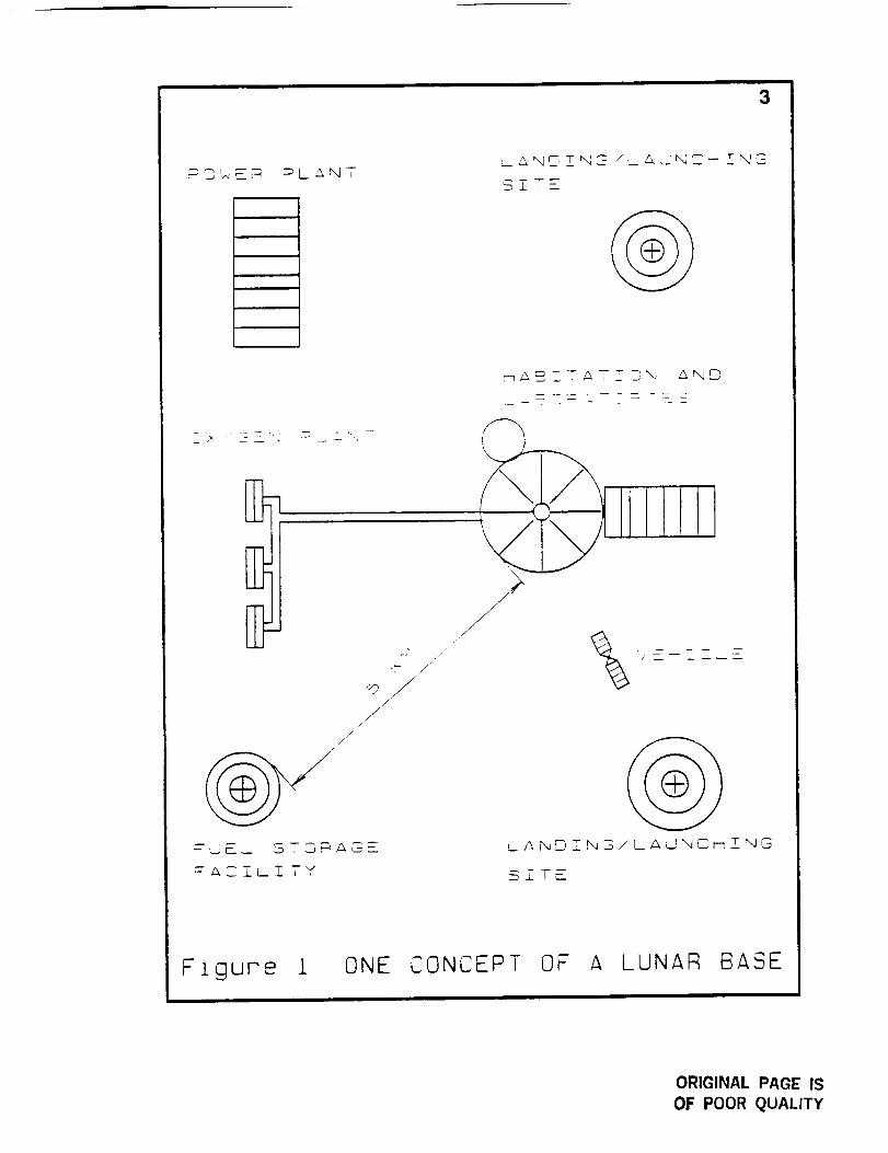
One concept of a lunar base has it comprised of separated
facilities such that the habitation and laboratory center is safely
away from the landing/launching,_ . sites and the power plant (see
Figure l). Storage garages, maintenance garages, and other facilities
are located within the base with the distance separating each facility
being dictated by safety factors. For example, landing and launching
sites are separated from habitation facilities to protect the astronauts
and equipment from errant space craft landings or launches, and
thrown dust by the engine blast.
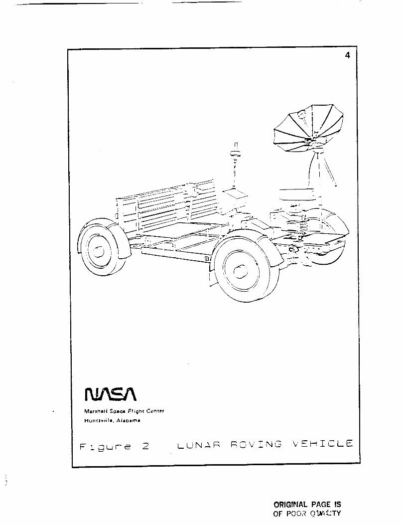
The team has designed an autonomous, teleoperated cargo
transporting system connecting these separated facilities. The
system will eliminate the need for manual cargo transportation and
thus replace the leading cargo transporting candidate, the lunar
roving vehicle (see Figure 2). A system that does not require manual
cargo transportation is preferred because it reduces the likelihood of
injury to the astronauts and frees them for more important tasks.
3
.//
/
_-U#-_- ST0_ '_-_-__
_ZT_T'3N _N2
/
/
SZT_
Figure i, ONE CONCEPT OF A LUNAR BASE
ORIGINAL PAGE IS
OF POOR QUALITY
4
Marshall Sgsca Flight C_ntef
Huntsvaile, Ata_arn=
_- i guu-e 2 LUNA_ _OVZNG YEHZCLE
ORIGINAL PAGE IS
OF POOR Q_._TY
5
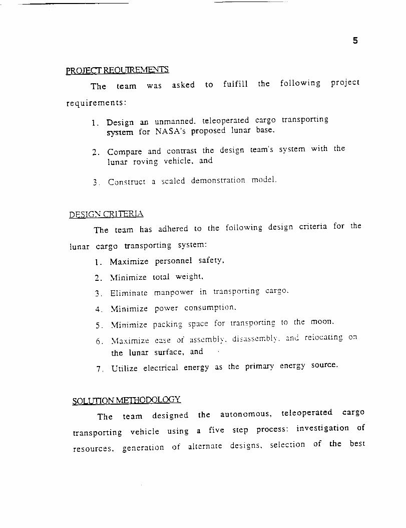
PROJECT REQUIRE.MLmNTS
The team was asked to fulfill the following
requirements:
1. Design an unmanned, teleoperated cargo transporting
system for NASA's proposed lunar base,
2. Compare and contrast the design team's system with the
lunar roving vehicle, and
3. Construct a scaled demonstration model.
project
DESIGN CRITERIA
The team has adhered to the following design criteria for the
lunar cargo transporting system:
I. Maximize personnel safety,
2. Minimize total weight,
3. Eliminate manpower in transporting cargo,
4. Minimize power consumption,
5. Minimize packing space for transporting to the moon.
6. Maximize ease of assembly, disassembly, and relocating on
the lunar surface, and
7. Utilize electrical energy as the primary, energy source.
SOLUTION ME'ITIQDOLOGY
The team designed the autonomous, teleoperated cargo
transporting vehicle using a five step process: investigation of
resources, generation of alternate designs, selection of the best
6
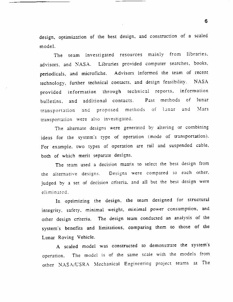
design, optimization of the best design, and construction of a scaled
model.
The team investigated resources mainly from libraries,
advisors, and NASA. Libraries provided computer searches, books,
periodicals, and microfiche. Advisors informed the team of recent
technology, further technical contacts, and design feasibility. NASA
provided information through technical reports, information
bulletins, and additional contacts. Past methods of lunar
transportation and proposed methods of lunar and Mars
transportation were also investigated.
The alternate designs were generated by altering or combining
ideas for the system's type of operation (mode of transportation).
For example, two types of operation are rail and suspended cable,
both of which merit separate designs.
The team used a decision matrix to select the best design from
the alternative designs. Designs were compared to each other,
judged by a set of decision criteria, and all but the best design were
eliminated.
In optimizing the design, the team designed for structural
integrity, safety, minimal weight, minimal power consumption, and
other design criteria. The design team conducted an analysis of the
system's benefits and limitations, comparing them to those of the
Lunar Roving Vehicle.
A scaled model was constructed to demonstrate the system's
operation. The model is of the same scale with the models from
other NASA/USRA Mechanical Engineering project teams at The
7
University of Texas at Austin to illustrate the interfacing between
the four different project teams' designs.
Finally, the team had weekly discussions with the faculty
advisor, Dr. Kris Wood, and the other student teams involved in the
NASA/USRA lunar base projects at The University of Texas at Austin.
These meetings provided guidance and ideas for the project.
During the investigation of resources, the team generated
several alternative designs to accomplish the need of cargo
transporung. The advantages and disadvantages of each design were
se,.non.listed and are discussed in the foilowine o,
ALTERNATE DESIGNS
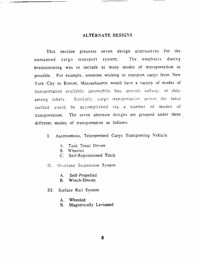
This section presents seven design alternatives for the
unmanned cargo transport system. The emphasis during
brainstorming was to include as many modes of transportation as
possible. For example, someone wishing to transport cargo from New
York City to Boston, Massachusetts would have a variety of modes of
transportation available: automobile, bus, aircraft, railway, or ship,
among others. Similarly, cargo transportation across the lunar
surface could be accomplished via a number of modes of
transportation. The seven alternate designs are grouped under three
different modes of transportation as follows:
Io Autonomous, Teleoperated Cargo Transporting Vehicle
A. Tank Tread Driven
B. Wheeled
C. Self-Repositioned Track
II. Overland Suspension System
A. Self-Propelled
B. Winch-Driven
III. Surface Rail System
A. Wheeled
B. Magnetically Levitated
8
9
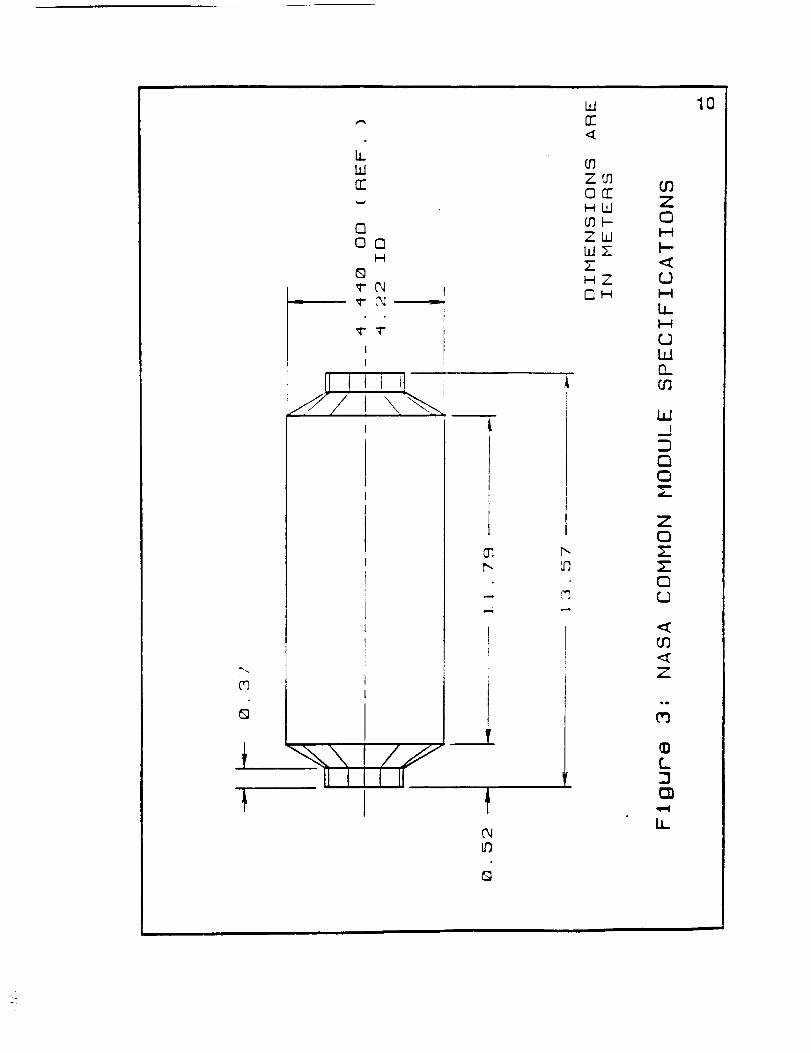
For the remainder of this section, the cargo containers are described,
the three modes of transportation are discussed, and the general
operation, advantages, and disadvantages of each of the seven
alternate designs are explained.
C.AA_,GO CONTAL'X'EP, S
Cargo for the lunar base will be brought from the earth to the
moon in one large, cylindrical cargo module (space station common
module/ measurin_ four and one half meters in diameter and
thirteen and one half meters in length (see Figure 3). This large
module will hold many smaller cargo containers and. following the
removal of these containers, will be used as a habitation module.
Since the module is so large and massive when fully-loaded, it
will not be transported to the base from the landing site in one trip.
Rather. the design team's transport system will haul the smaller
cargo containers separately to their destinations within the lunar
base. Therefore, approximately ten to fortv trips are necessary
between sites for container volumes of I0 and 2 cub'ic meters,
respectively.
AUTONOMOUS. TELEOPERATED CARGO TRANSPORTING
An autonomous, teleoperated cargo transporting vehicle is
operated independently of any rail or guide. The "driver" operates
the vehicle either from the lunar base or from the earth through
teleoperation. If teleoperated from earth, a two-and-a-half second
lag accompanies the signal, causing slower vehicle speeds because
CO
6_
hhlrr
oOO
I-.48
'I- f,,l _
"4-
O";r',-
t
G
I..drr
Z0
O0ZLdZH0
i
03rrW
LOZ
Z
10
O3Z¢3
_3
LL
bJO_O3
bJI
m
m(3
z¢3zz
_3
Z
_Q
_3
@I_
LL
11
the operator does not have instantaneous control of the vehicle.
Teleoperation allows the astronauts to concentrate on other tasks
and, since astronauts are not needed to transport the cargo, the
chances of an accident with injury are reduced. Three possible
means of supporting and propelling this vehicle are through tank
treads, wheels, and setf-repositioning track.
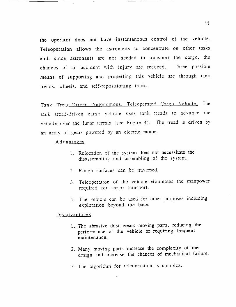
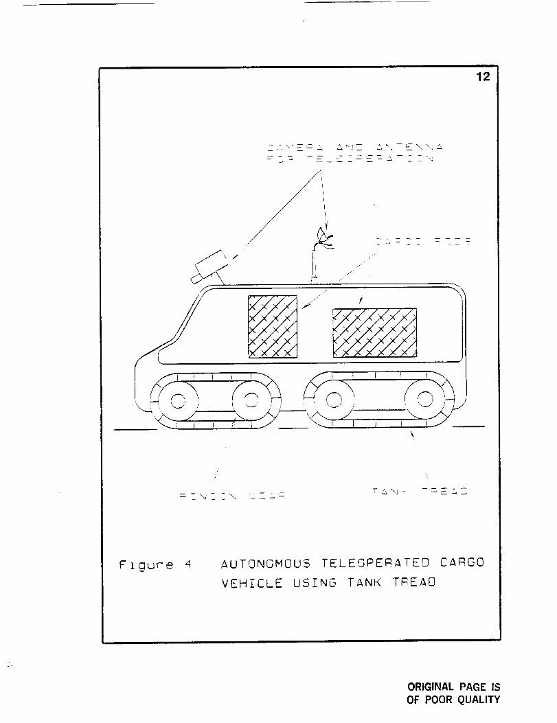
Tank Tread-Driven Autonomous, Teleoperated Cargo Vehicle. The
tank tread-driven car__o vehicle uses tank treads to advance the
vehicle over the lunar terrain (see Figure 4). The tread is driven by
an array of gears powered bv an electric motor.
Advantages
I. Relocation of the system does not necessitate the
disassembling and assembling of the system.
2. Rough surfaces can be traversed.
3. Teleoperation of the vehicle eliminates the manpower
required for cargo transport.
4. The vehicle can be used for other purposes including
exploration beyond the base.
Disadvantages
1. The abrasive dust wears moving parts, reducing the
performance of the vehicle or requiring frequentmaintenance.
2. Many moving parts increase the complexity of the
design and increase the chances of mechanical failure.
3. The algorithm for teleoperation is complex.
12
-- '4 ----
t
/
,/'
/
F tgure 4 AUTONOMOUS TELEOPERATEO CARGO
VEHICLE USING TANK T_EAO
ORIGINAL PAGE IS
OF POOR QUALITY
13
4. Teleoperation from the earth would slow the vehicle
response because the Earth-Moon distance causes a 2.5
second delay of signal travel.
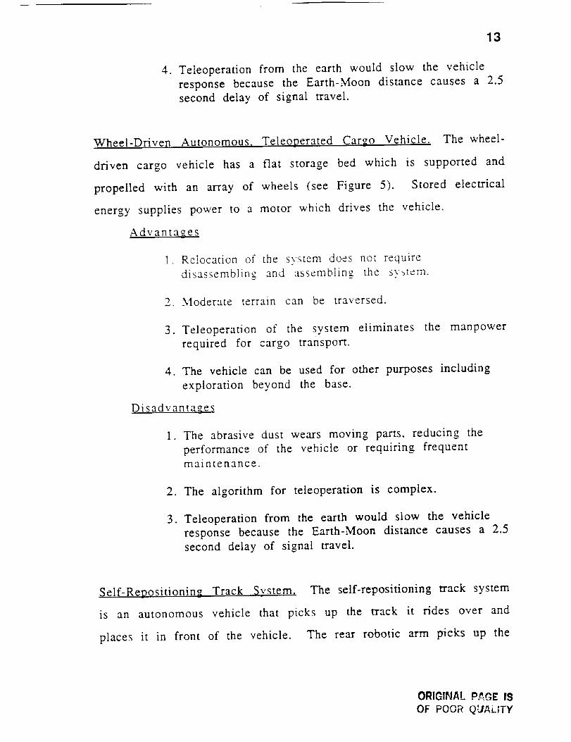
Wheel-Driven Autonomous, Teleoperated Cargo Vehicle. The wheel-
driven cargo vehicle has a flat storage bed which is supported and
propelled with an array of wheels (see Figure 5). Stored electrical
energy supplies power to a motor which drives the vehicle.
Advantages
1. Relocation of the system does not require
disassemblino_ and assembling_ the system.
2. Moderate terrain can be traversed.
3. Teleoperation of the system eliminates the manpower
required for cargo transport.
4. The vehicle can be used for other purposes including
exploration beyond the base.
Disadvantages
1. The abrasive dust wears moving parts, reducing the
performance of the vehicle or requiring frequent
maintenance.
2. The algorithm for teleoperation is complex.
3. Teleoperation from the earth would slow the vehicle
response because the Earth-Moon distance causes a 2.5
second delay of signal travel.
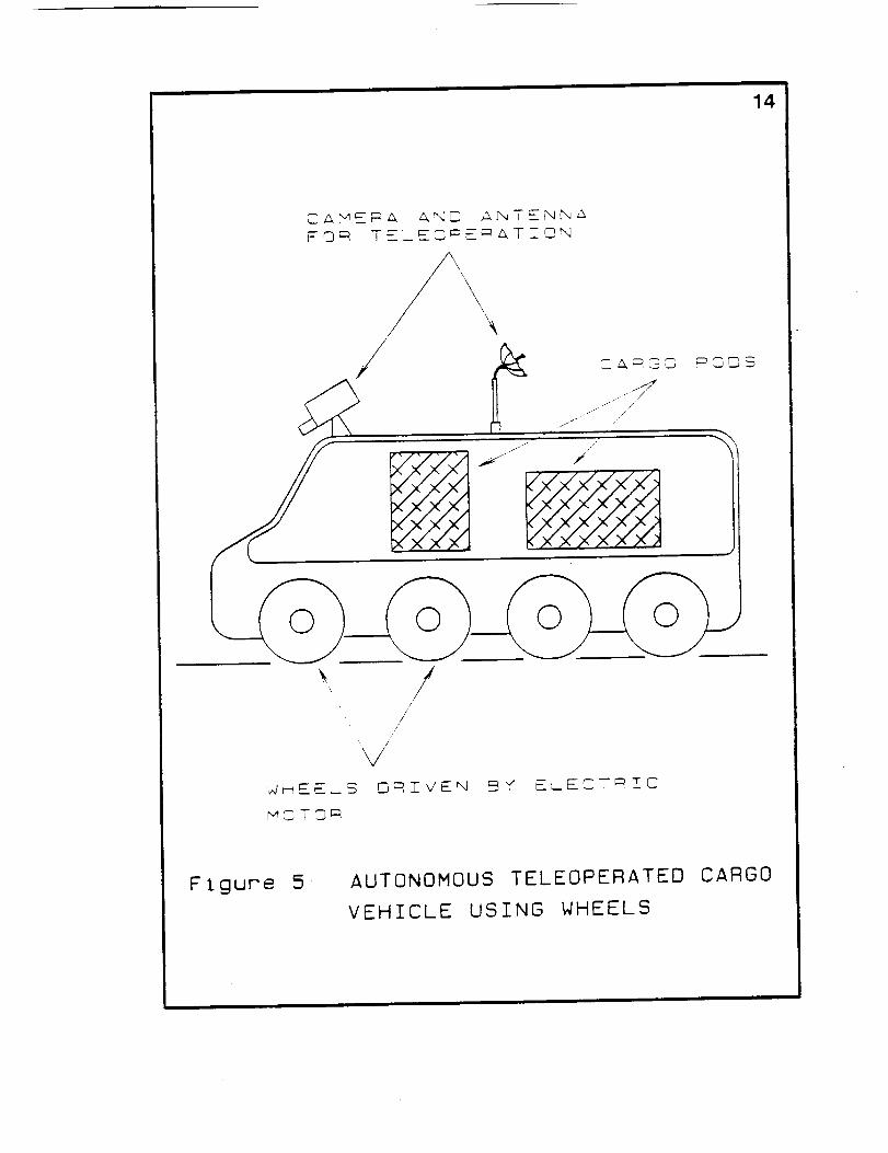
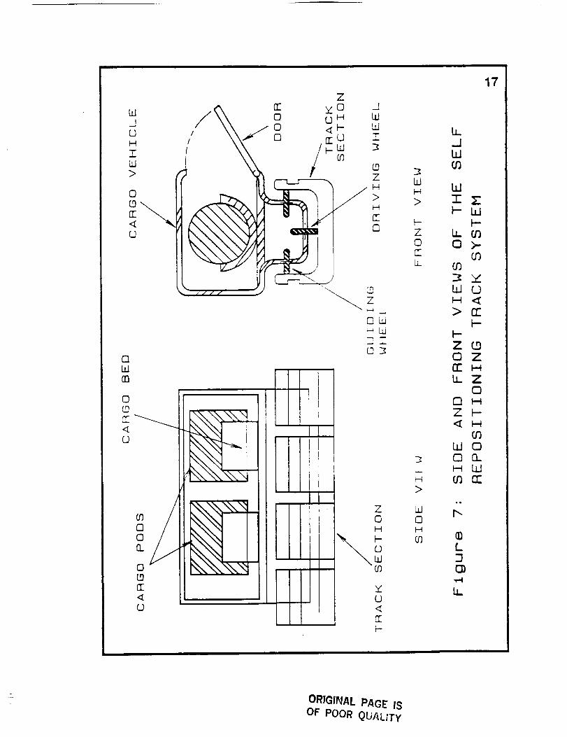
Self-Repositioning Track System, The self-repositioning track system
is an autonomous vehicle that picks up the track it rides over and
places it in front of the vehicle. The rear robotic arm picks up the
ORIGINAL P.h_E IS
OF POOR Q._/ALITY
iii ii i
14
Ca_G3
, /" /
//
"_V/"
_S _ECY_C
_0_9
Ftgure 5, AUTONOMOUS TELEOPERATED CARGO
VEHICLE USING WHEELS
18
track sections that the vehicle rides on and carries them to the roof.
Once on the roof, the track sections are carried forward on a
conveyor belt and lowered by the front robotic arm to the ground in
front of the vehicle (see Figures 6 and 7).
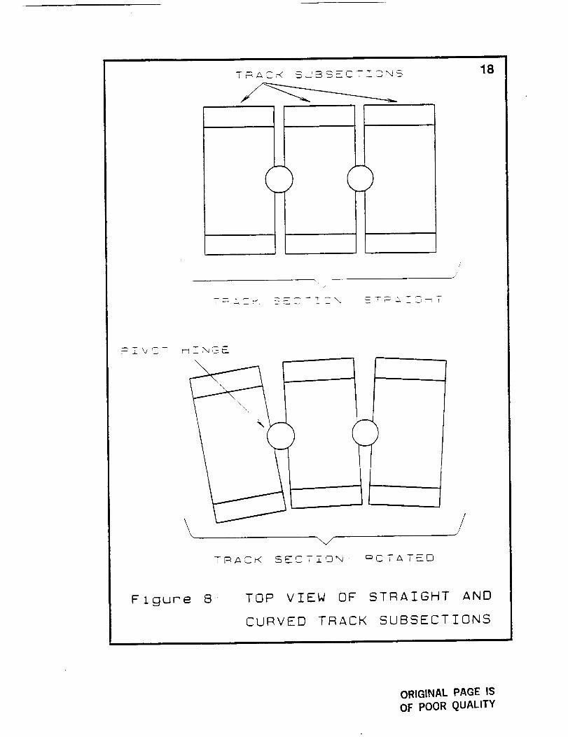
Each track section has three subsections which are connected
by hinges with self-locking mechanisms. Upon turning, a track
section is moved on the track direction molder which forces an angle
between the subsections. The three subsections are held at this
an-_!e bv the self-tockin_, mechanisms (see Figure 8_.
The vehicle is supported and guided through the track bv
wheels. The power source which supplies electricity to the motors is
stored electrical eriergy.
Advantages
1. Relocation of the system does not require
disassembling and assembling the system.
"_ The vehicle has a low rollin_, resistance durin_
contact with the track.
":. Te!eoperation of the system eliminates the manpower
required for cargo transport.
4. The vehicle can be used for other purposes including
exploration beyond the base.
Disadvantages
1. The system needs precise control of track position.
2. The need for precise control slows the system.
3. The system requires a flat surface for operation.
_O_OTZC
I!
16
Figure 6. SELF-REPOSITIONING TRACK SYSTEM
ORIGINAL PAGE IS
OF POOR QUALITY
WJ0H
"FW>
0
rr<_U
(3Ldrn
0
4
008.
0
n-
o
z
n- E00 oH Ld0 4_- Ld
O _© "rif?
Z_ H
H
_2
_ rn
Z
OLd_hJDZ
Z0H
0W
Y0<_rFF-
Wh_
>
Z0
LL
H
>
1,10H
O_
17
b__JW_0
W
T _-b- W
N-LL tO0 >-
tOtO
W 0
> rr
N-Z0 ZrrLL Z
00Z
W 00 O_
LO
tO n"
b_
Q)(.
LL
ORIGINAL PAGE IS
OF POOR QU/'_LITY
18
()
_TUCT
/
\\ X/
I
TRACK SECTION ROTATED
/
j'
/
Flgure 8 TOP VIEW OF
CURVED TRACK
STRAIGHT AND
SUBSECTIONS
i
ORIGINAL PAGE IS
OF POOR QUALITY
19
4. Teleoperation from the earth would slow the vehicle
response because the Earth-Moon distance causes a 2.5
second delay of signal travel.
5. The driving mechanisms for translational motion and
for the positioning of the tracks is complex.
OVERLAND SUSPENSION SYSTEM
An overland suspension system carries the cargo above the
lunar surface so as to avoid rough terrain and abrasive dust clouds.
Since lunar dust is so abrasive, it presents a problem of wear as it
works its way between movin,,a parts.
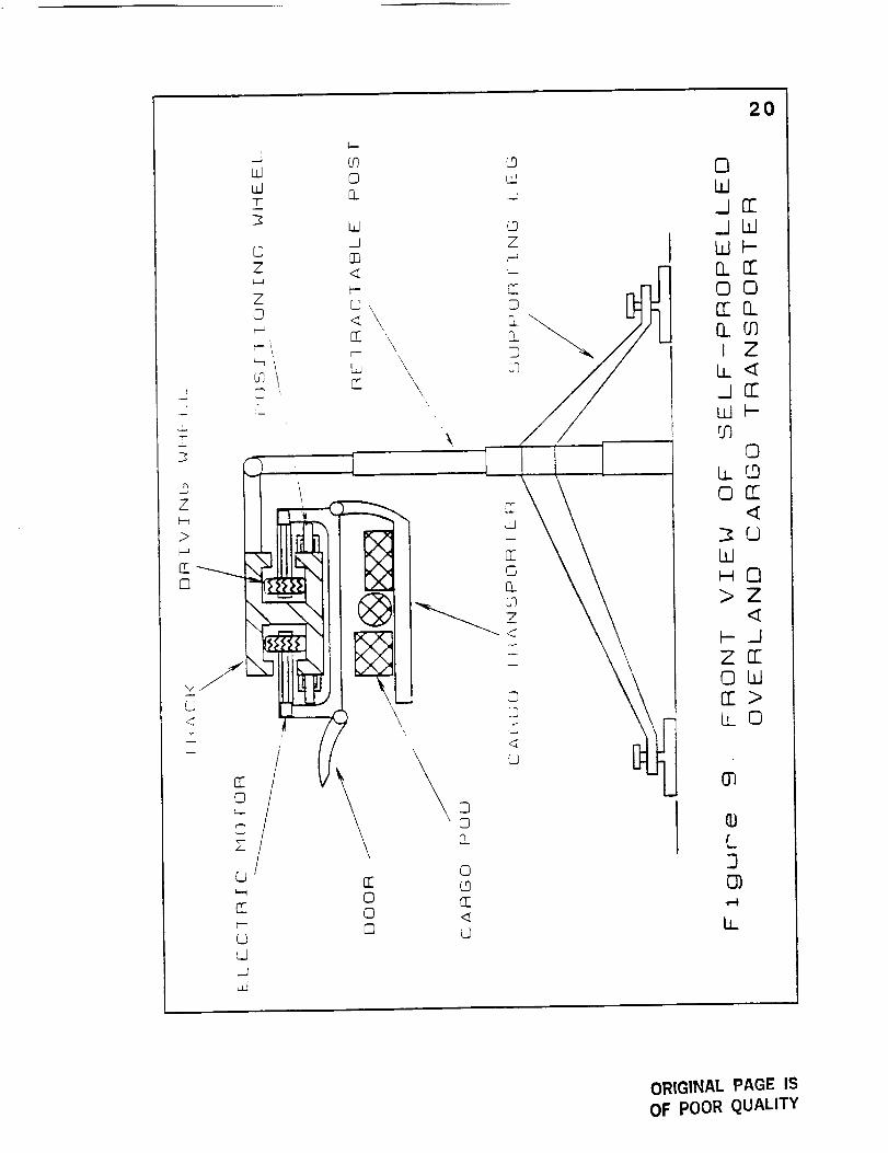
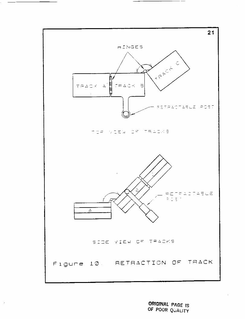
Retractable posts are erected to support a rigid, but foldable
track on which the cargo transporter will travel (see Figure 9).
Retractable posts and tracks facilitate the relocation of the system.
One possible way of retracting the system is by folding as illustrated
in Figure 10. The suspended cargo holder is propelled in one of two
ways, either self-propelled or pulled bv a winch-driven cable.
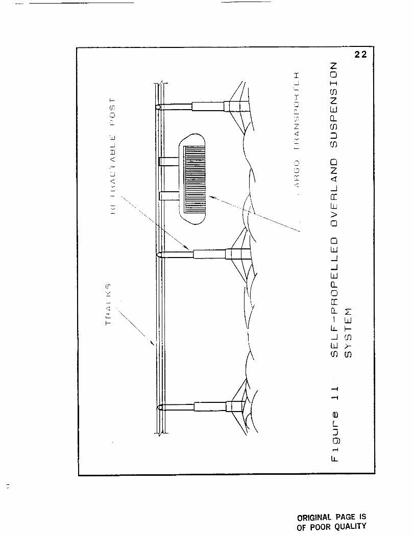
Self-Propelled Overland Suspension System. The self-propelled
version of the overland suspension system contains its own motor
and energy storage devices (see Figure 11). Power is transmitted
from the motor through gears and wheels that roll on the suspended
rail to provide motion.
Advantages
1. The system avoids creating lunar dust clouds, whichcan enter between moving parts and promote wear.
2. The system can traverse rough terrain.
ORIGINAL PAGE ISOF POOR QUALITY
Z
>
0
V
r--
2O
OW/rr..JWWt--0_rrOOrr0_Q., (.;)I Z
I.L<[,.jrrLdFg.-)
©t.z. r,...0on"
L.dHO>Z
F,_]ZrrOWrr>LLO
03
Q)L3O)
Ii
ORIGINAL PAGE IS
OF POOR QUALITY
21
T_ACS A
_I_..T__GES
-CST
, t-'-
A
Si_E ViEd O_ T=_CKS
Flgume l_ RETRACTION OF" TRACK
ORIGINAL PAGE IS
OF POOR QUALITY
O_0.3_
lm
M<
U
\\
\
\
Z0_ 0r,I H=- O0,'T"
F_ ZW
s_, ELz O0< 2l
tO
L_rr<
0Z
.JOELO>0
0LO
_JW
O_OFF
O_ ZI Ldh b--J COW >-
,-4
L3O)
LL
22
ORIGINAL PAGE ISOF POOR QUALITY
23
3. Automation and teleoperation are simplified since the
system is guided by rail.
4. Several vehicles can be operated on the system at thesame time.
Disadvantages
1. Extensive disassembly and assembly is required forrelocation.
2. System disassembly and assembly requires extensive
power.
3 Extensive material needs cause hi,,h system weieht
and volume.
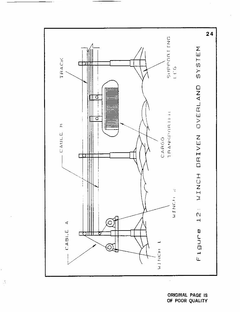
Winch-Driven Overland Suspension System, The winch-pulled
system requires that a cable be attached to the suspended cargo
transpor:er, looped around the system, and attached to the
transporter's other side. The cable is driven bv a winch, pulling the
cargo towards the intended destination either forward or backward
(see Figure 12).
Advantages
1. The system avoids creating lunar dust clouds, which
can enter between moving parts and promote wear.
2. The system can traverse rough terrain,
3. Automation and teleoperation are simplified since the
system is guided by rail.
4. Several transporters can operate at the same time.
ORIGINAL PAGE" ISOF POOR QUALiTy
II1.
litpitIll
_._ Ill
iltill
t I
I
i
m
i
i
IIIill
III _
£
Z
s© OC© Z
4
©Z
24
W
>-O_
nZ
_J
EELd>
©
ZW>I.-N
rrO
I0ZI--{
,,.-I
[30_
U_
ORIGINAL PAGE IS
OF POOR QUALITY
25
5. The power supply and motor remain in one central
location.
Disadvantages
1. Extensive disassembly and assembly is required forrelocation
2. System disassembly and assembly requires extensive
power.
3. Extensive material needs cause high system weight
and volume.
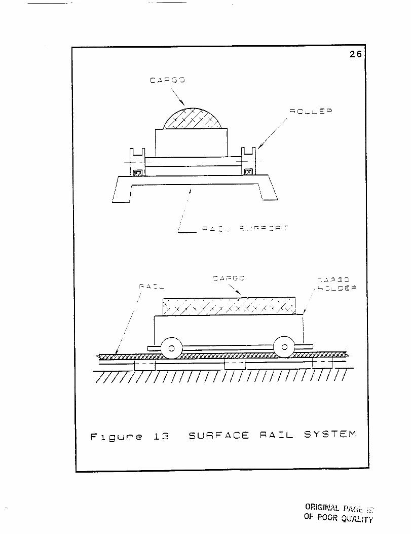
SURFACE RAiL SYSTEM
The surface rail system includes any rail or track svstem that is
laid over the lunar surface and guides a vehicle that carries cargo
from one site to another. The vehicle can roll on wheels or be
magnetically levitated (see Figures 13 and 14). Power to the vehicle
is supplied by stored electrical energy, and in the case of magnetic
levitation, power to the rail originates from the power plant.
The system is semi-permanent. A rail is laid down completely
between two sites, vet it can be disassembled and relocated. This
procedure of disassembly and assembly, however, requires the use
of an autonomous vehicle to carry the rail, and astronauts or robots
to lay and connect it.
Wheeled Surface Rail System. The rollers or wheels of this system
roll along grooves in the surface rail which may have one of several
configurations designed for stability and control. An on-board
Ill i i
26
/
/
/
//"
,/
r:_E_ \" _c_jr
__.,-_,,y,<..,,,'_-(f>-,<-,<-,,,<-_-_ j.t-,<',<.,<-,,'t.,<',<-,,',<-,<',<'_
///////11 II I I I I I11 111t t I 11 11177-
Figure L3 SURFACE RAIL SYSTEM
ORI_INAL PA(_E 7S
OF POOR QUALITY
w
.L
d,
,k\
\\
L.._
Z
._.1
n'-
U_
27
n_
r_
G
Z
I---
Z
Z
U_
ORIGINAL PAG_ ISOF POOR QUALITy
28
battery supplies energy to a motor to propel the vehicle along the
track.
Advantages
1. Because of stable control, moderate speeds are
possible.
2. Harmful dust clouds are not created since the vehicle
does not come into contact with the ground.
3. Automation and teteoperation are simplified since the
system is guided bv rail.
X. Several vehicles can be operated on the system at the
same time.
5. The simple meghanical structure has few moving
parts and is therefore reliable.
6. Simple, light-weight vehicles offer low power
requirements.
Disadvantages
1. Extensive rail laying is required.
" Extensive disassemblin_ =_. ,, and assemblin,, of the rail
consumes large amounts of power.
3. Total system weight and volume is large because of
the amount of rail involved.
4. The system can only traverse light to moderate
terrain.
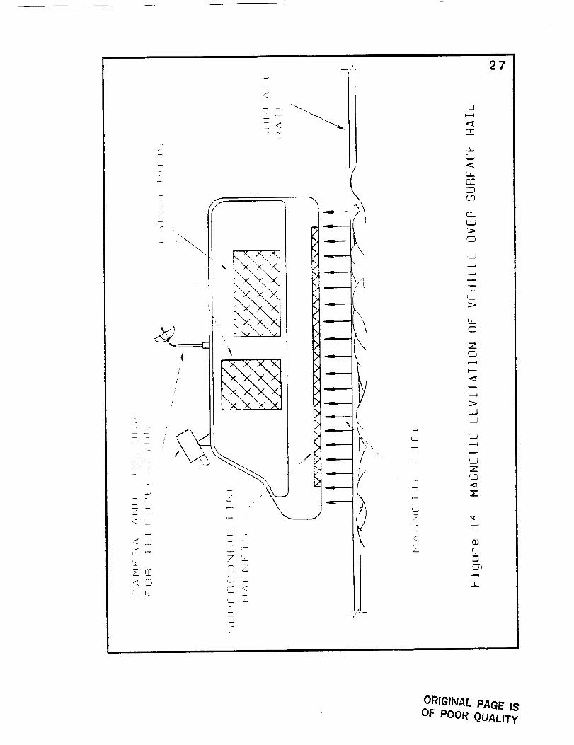
Magneticallv Levitated Surface Rail System. A levitated surface rail
svstem operates on the same principles as earth-bound magnetically
levitated high speed trains. The vehicle glides over the track
20
levitated by the repelling forces of the magnetic fields in the rail and
vehicle. The suspension is created between vehicle magnets and the
electrically conducting track. A time varying magnetic field
eminating from the track propels the vehicle forward or backward.
Advantages
1. Because of stable control, moderate speeds are
possible.
2. Harmful dust clouds are not created since the vehicle
does not come into contact with the ground.
3. Automation and teleoperation are simplified since the
system is guided by rail.
4. Several vehicles can be operated on the svstem at the
same time.
5. Wear is not a factor since the vehicle does not contact
the rail.
Disadvantages
1. Power requirements are high.
2. Extensive track laying is required.
3. Extensive disassembling and assembling of the rail
consumes large amounts of power.
4. Total system weight and volume is large because of
the amount of rail involved.
5. The system can only traverse light to moderate
terrain.
30
The seven designs were compared in a decision matrix to
identify the best design according to certain design criteria such as
weight, manpower, safety, power consumption, portability, and
reliability. Two modes of decision were considered: at the system
level (among the three modes of transportation) and at the
subsystem level (among the designs within the modes of
transportation). The interaction with other lunar base systems such
as the cargo loader and unloader were also taken into account in the
decision matrix.
DESIGN SOLUTION
The Self-Repositioning Track Vehicle (SRTV) best meets the
design criteria of the seven designs considered. The tool used to
identify the best design among the alternatives was a decision matrix
where each design is judged according to fifteen design criteria (see
Appendix A). For the remainder of this section, the operation of the
SRTV is explained, the assumptions for operation are discussed, six
areas of design emphasis are explained, and a comparison with the
lunar roving vehicle is made.
QPERATIQN OF THE SRTV
The SRTV consists of a vehicle that rolls over a series of
interconnected track sections. Once a track section has been
traversed by the vehicle, it is picked up off the ground, brought
forward on a conveyor be!t, and placed onto the ground in front of
the vehicle. The vehicle moves on wheels over the tracks and is
capable of either forward or backward motion. Cargo is stored in the
cargo bay between the vehicle chasis and the upper platform on
which the track sections are brought forward.
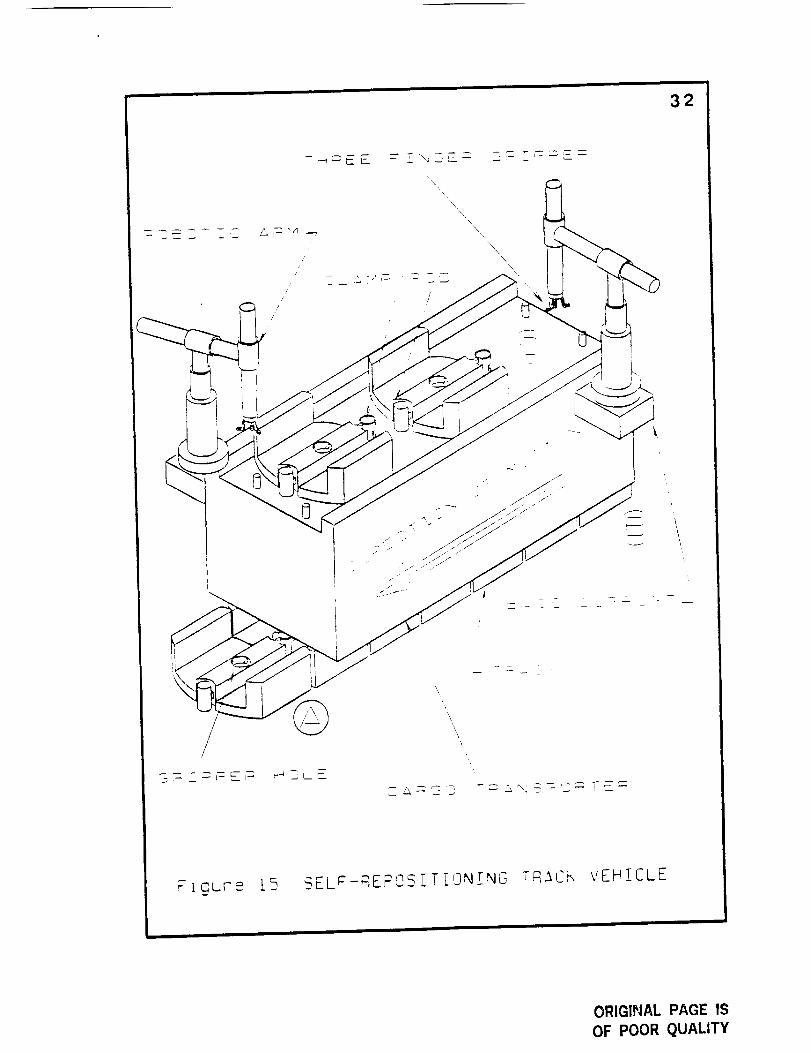
The SRTV is shown in Figure 15, and its operation following the
lettered steps in the figure is as follows:
1. A track section is placed onto the ground in front of the
approaching vehicle at point A.
2. The vehicle rolls over the track section.
31
32
/'
/
/
//
/
, ///
_ u-_
\
\
\\
\\,
\\
\
\,
/!
I¸,
IiI
i I
iI
Ftgure [5 _ELF-RErOS/T[ON[NG Tq_Cm VEHICLE
ORIGINAL PAGE IS
OF POOR QUALITY
:13
3. Once the vehicle has passed over the track section at point B,
the rear robotic arm lifts the track off the ground and onto
the platform above the cargo bay.
4. The track sections are pulled forward at point C.
5. The forward robotic arm places the track section onto the
ground in front of the vehicle and the cycle is repeated.
.ASSUMm'TON$
The assumptions made in generating the design of the SRTV
are made to simplify the vehicle design and alIow for cutting edge
technology to be used in making an advanced system. The
assumptions are as follows:
1. The surrounding terrain is fiat and void of a high
density of rocks and holes whose diameters are larger
than 0.1 meters.
2. Teleoperation and automation technology is available.
3. Robotics technology is available.
4. A lifting system loads and unloads cargo onto and off ofthe vehicle.
DESIGN EMPHASIS
The team has directed its concentration into six areas of the
SRTV design:
1. Track Configuration and Interconnecting,
2. Track/Vehicle Interface (suspension, driving and guiding
wheels),
3. Robotic Arm Motion and Operation.
4. Materials,
ORIGINAL PAGE |S
OF POOR QUALITY
5. Teleoperation Systems, and
6. Cargo Bay Dimensions.
34
Track Configuration. The track serves several purposes. First, the
interface between vehicle and riding surface is controlled, reducing
rolling friction. Second, dust clouds are kept away from moving
parts, mainly the wheel assemblies. Third, teteoperation is reduced
in complexity because of the track-guided configuration.
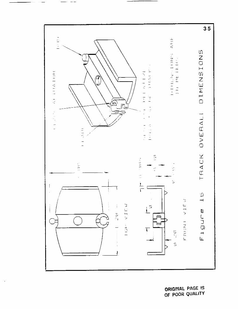
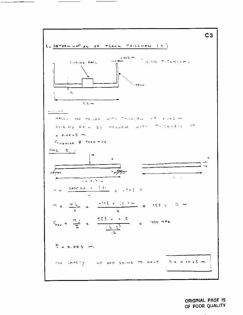
The track system is comprised of nine sections. Each track
section consists of a rod and clamp coupler, a middle guiding rail, two
side-walls, and cleats (see Figure 16). Each track section is 1 meter
long, 1.2 meters wide, and 0.3 meters tall.
As each track section is set down in front of the vehicle, the
robotic arm slides the male connection into the female connection of
the previous track section. When the track sections are flush with
each other, an actuator locks the joint preventing any separation or
vertical movement of track sections, yet allowing slight twists and
bends to account for surface irregularities. As the rear wheel
assembly of the vehicle passes completely over a track section, the
actuator releases as it senses no weight on the track. The section is
then picked up by the rear robotic arm.
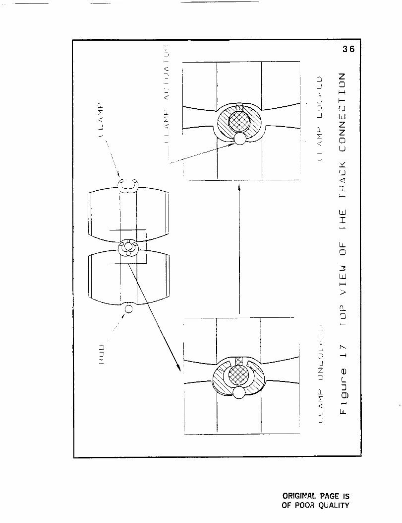
The track section contains a male connector (rod) at one end
and a female connector (clamp) at the other (see Figure 17). The
torque produced on the coupling by unevenly laid track sections
tends to unlock the clamp. To compensate for a maximum offset
angle of 5 degrees between two adjacent track sections and avoid
I
Is
f
Z
S
- i
L
>
r
7
z
'.bJ
%
35
03Z©t.--4
rj3ZL.dZI--t
0
i
q-
EL.,d>
©
L.)
r.O-'4
L3
,,--t
I.,,L
ORIGINAL PAGE IS
OF POOR QUALITY
S<,
\,
'\
I
f
,9-
L--
<
3¸<
2_7<,
!
1
/ _- !
Z,_J
,....
W
ZZ
0
36
W
-F
LL
©
Ld
o_
J
ZD L
],!
L
ORIGlr',wA[ PAGE IS
OF POOR QUALITY
37
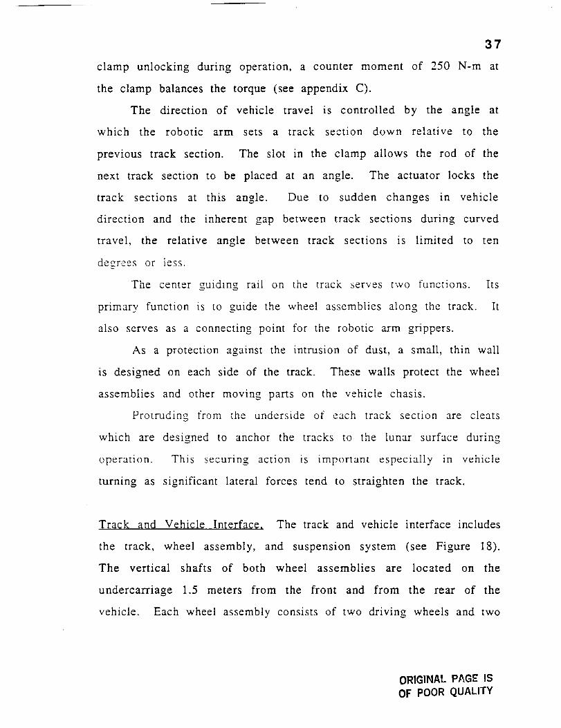
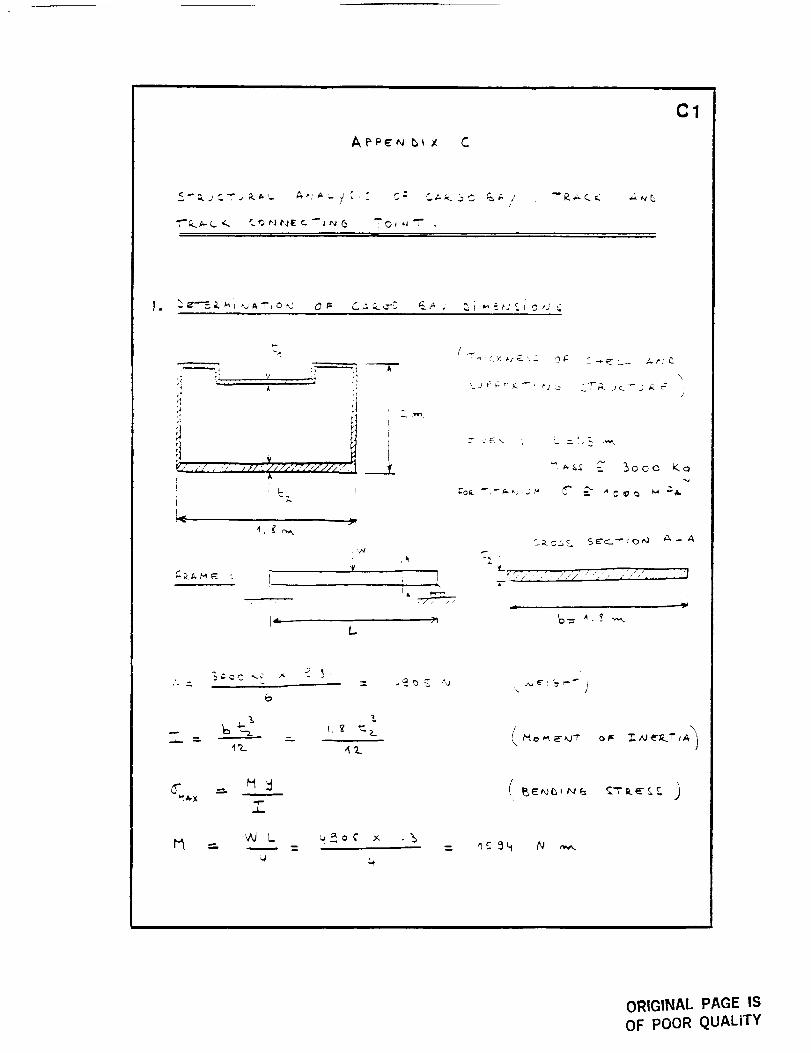
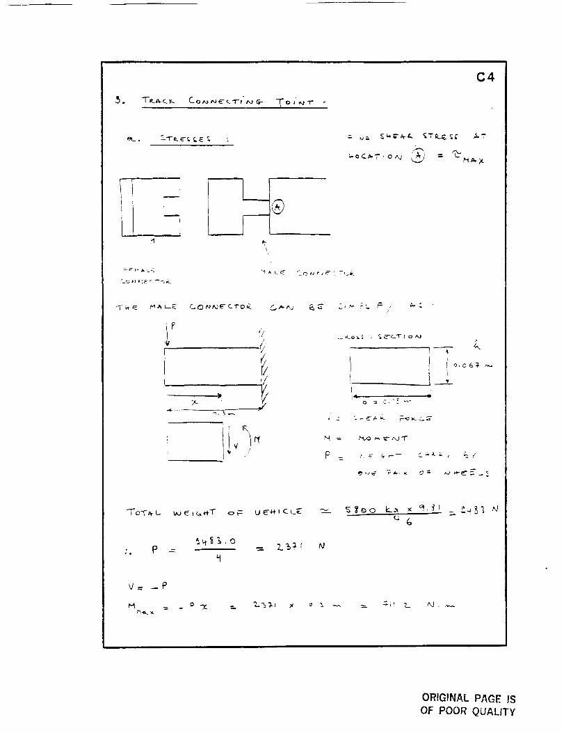
clamp unlocking during operation, a counter moment of 250 N-m at
the clamp balances the torque (see appendix C).
The direction of vehicle travel is controlled by the angle at
which the robotic arm sets a track section down relative to the
previous track section. The slot in the clamp allows the rod of the
next track section to be placed at an angle. The actuator locks the
track sections at this angle. Due to sudden changes in vehicle
direction and the inherent gap between track sections during curved
travel, the relative angle between track sections is limited to ten
degrees or less.
The center guiding rail on the track serves two functions. Its
primary function is to guide the wheel assemblies along the track. It
also serves as a connecting point for the robotic arm grippers.
As a protection against the intrusion of dust, a small, thin wall
is designed on each side of the track. These walls protect the wheel
assemblies and other moving parts on the vehicle chasis.
Protruding from the underside of each track section are cleats
which are designed to anchor the tracks to the lunar surface during
operation. This securing action is important especially in vehicle
turning as significant lateral forces tend to straighten the track.
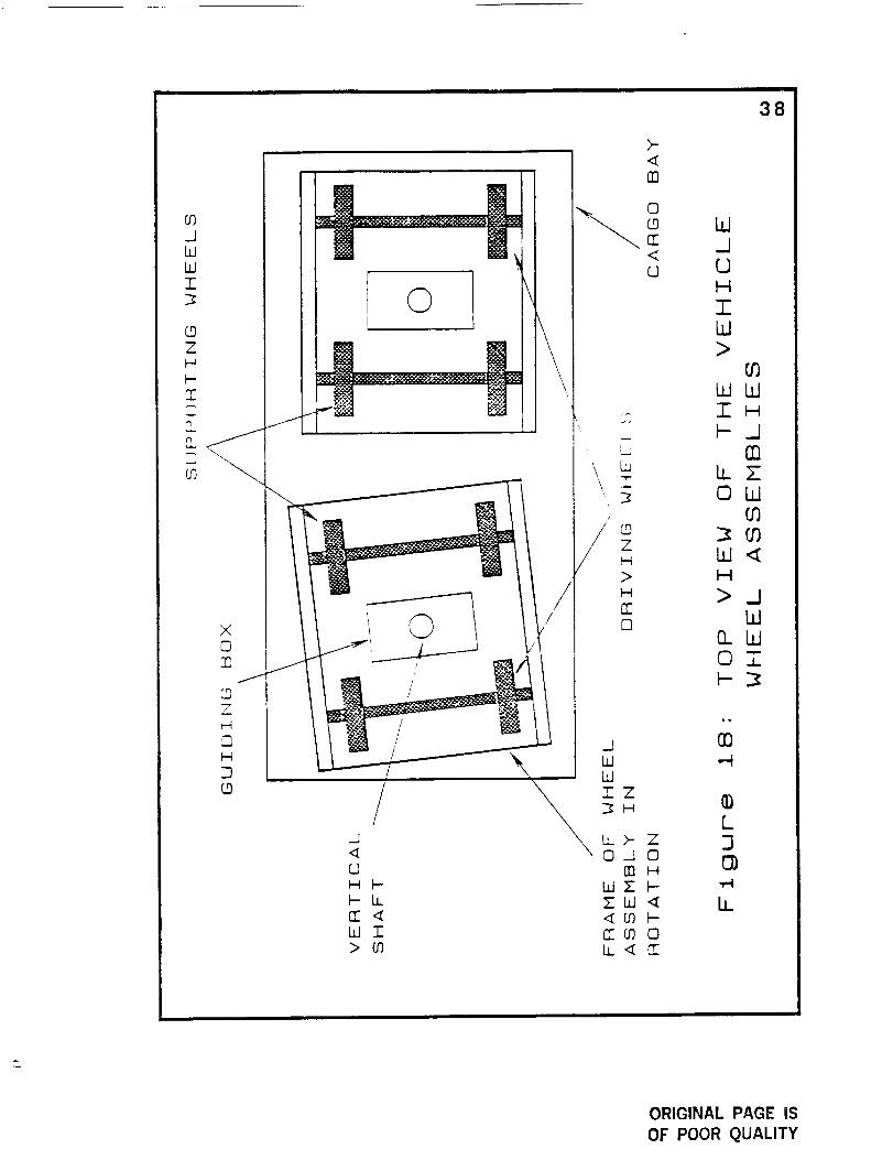
Track and Vehicle Interface, The track and vehicle interface includes
the track, wheel assembly, and suspension system (see Figure 18).
The vertical shafts of both wheel assemblies are located on the
undercarriage 1.5 meters from the front and from the rear of the
vehicle. Each wheel assembly consists of two driving wheels and two
ORIGINAL PAGE ISOF POOR QUALITY
_0IWWZ
ZH
rF0
O_D
t
0!
\
>-
nn
0
C<O
Wd0H
IbJ
38
>tO
WWZH
0]b_7OLd
01
W_H
>_JW
O.W01
00
L]
lJ
ORIGINAL PAGE iS
OF POOR QUALITY
39
non-driving, supporting wheels for a total wheel count of eight. Each
wheel assembly has a common frame rigidly connecting the driving
and supporting wheel axles. This frame attaches to a vertical shaft
which allows rotation of the wheel assembly relative to the vehicle
during curved motion.
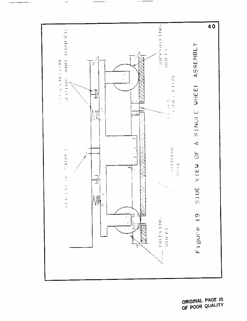
The driving and supporting wheels have the same
configuration and consist of titanium wheels attached to the ends of a
0.8 meter axle, with the driving axle geared to an electric motor (see
Figure 19). The two parallel axles are _eparated a distance, of 1.3
meters so that the vehicle toad is spread over two track sections per
wheel assembly at all times. Both sets of wheels can never cross the
track gap at the same time.
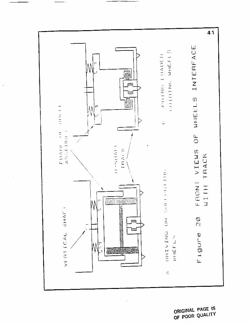
Attached to the wheel assembly frame beneath the vertical
shaft is a "U"-shaped guide which controls the orientation of the
wheel assembly (see Figure 20). The guide follows a monorail down
the center of the track and supports part of the load when the
wheels cross over the gaps between track sections.
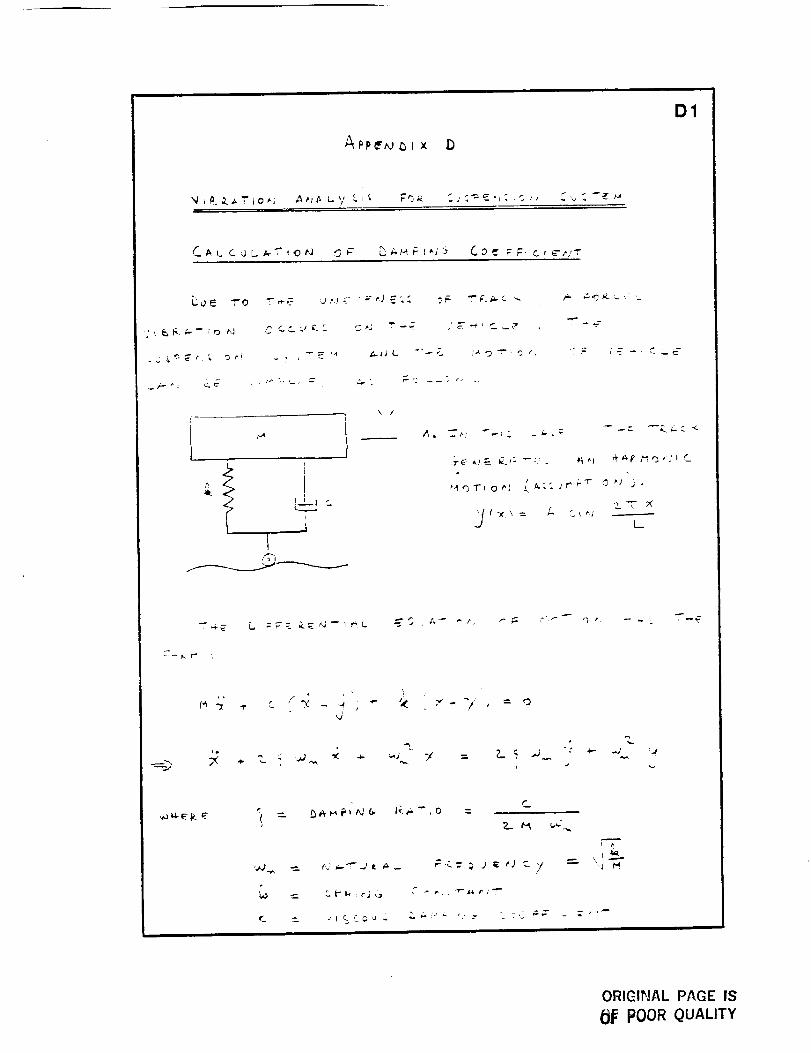
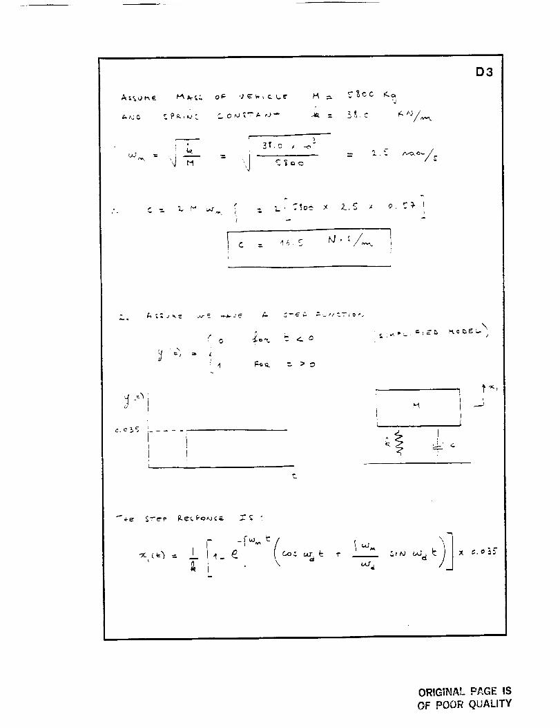
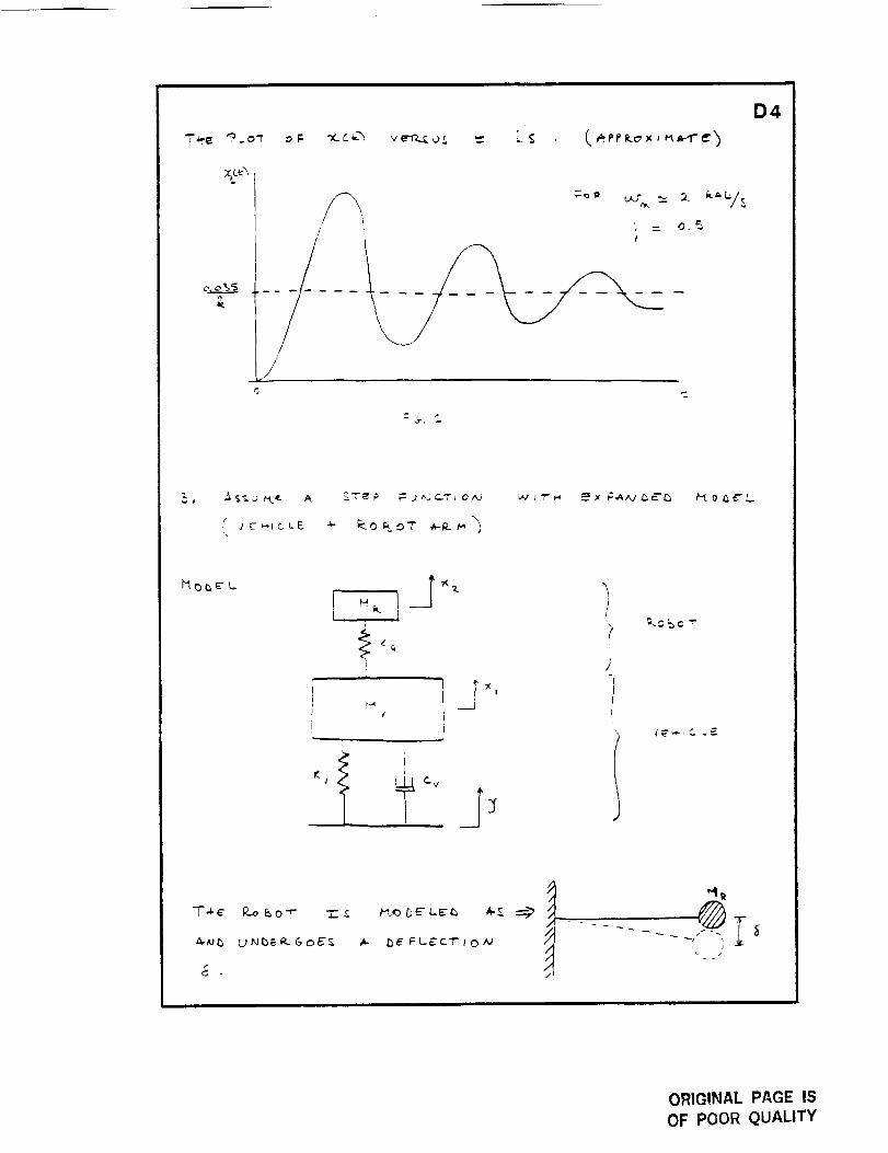
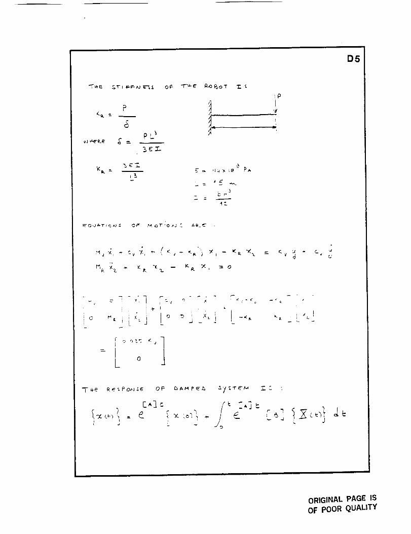
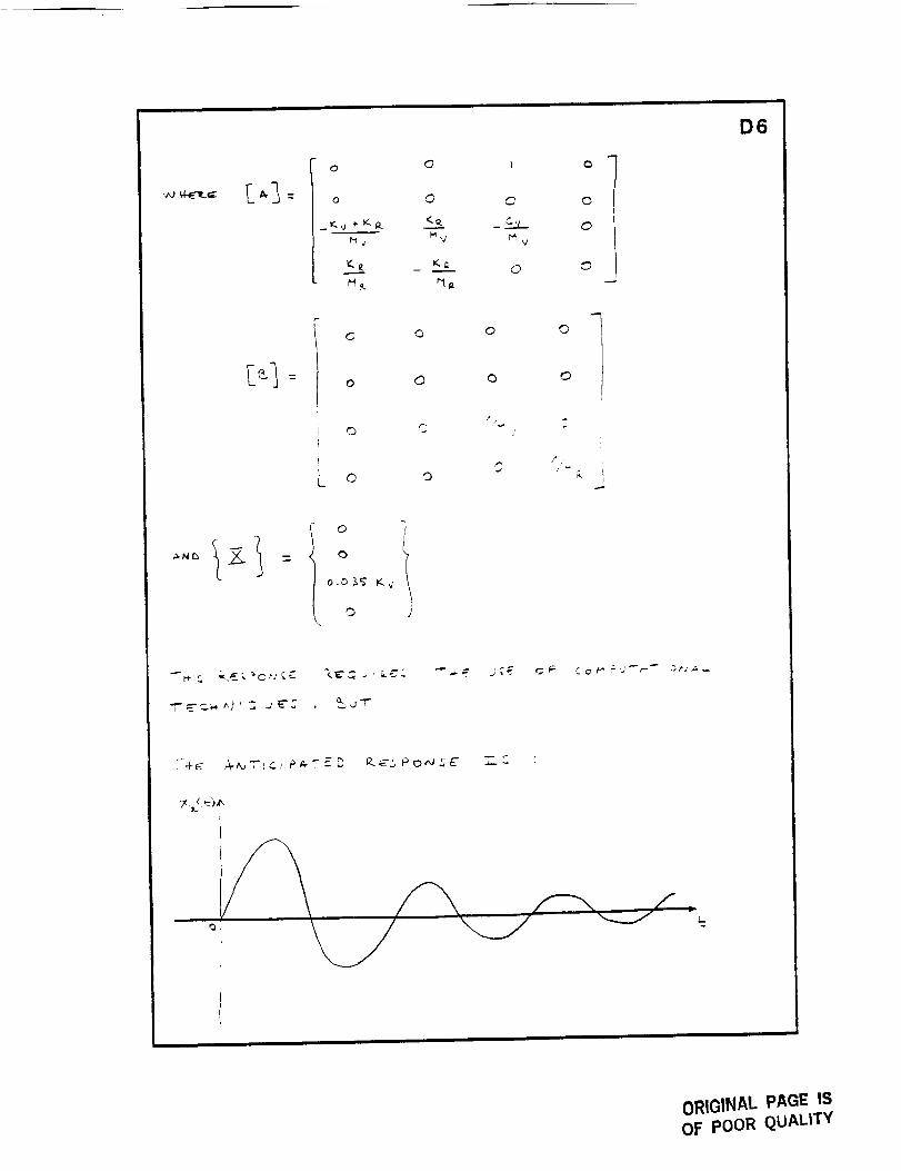
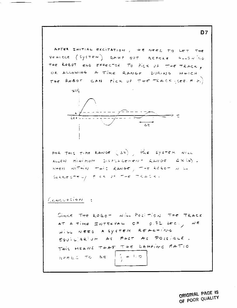
The suspension system consists of springs and shock absorbers
that are packaged around the vertical shaft of each wheel assembly.
The springs and shock absorbers support the load of the vehicle and
damp out the effects of surface irregularities. The vibrations caused
by surface irregularities affect the positioning precision of the robotic
arm and must be quickly damped out.
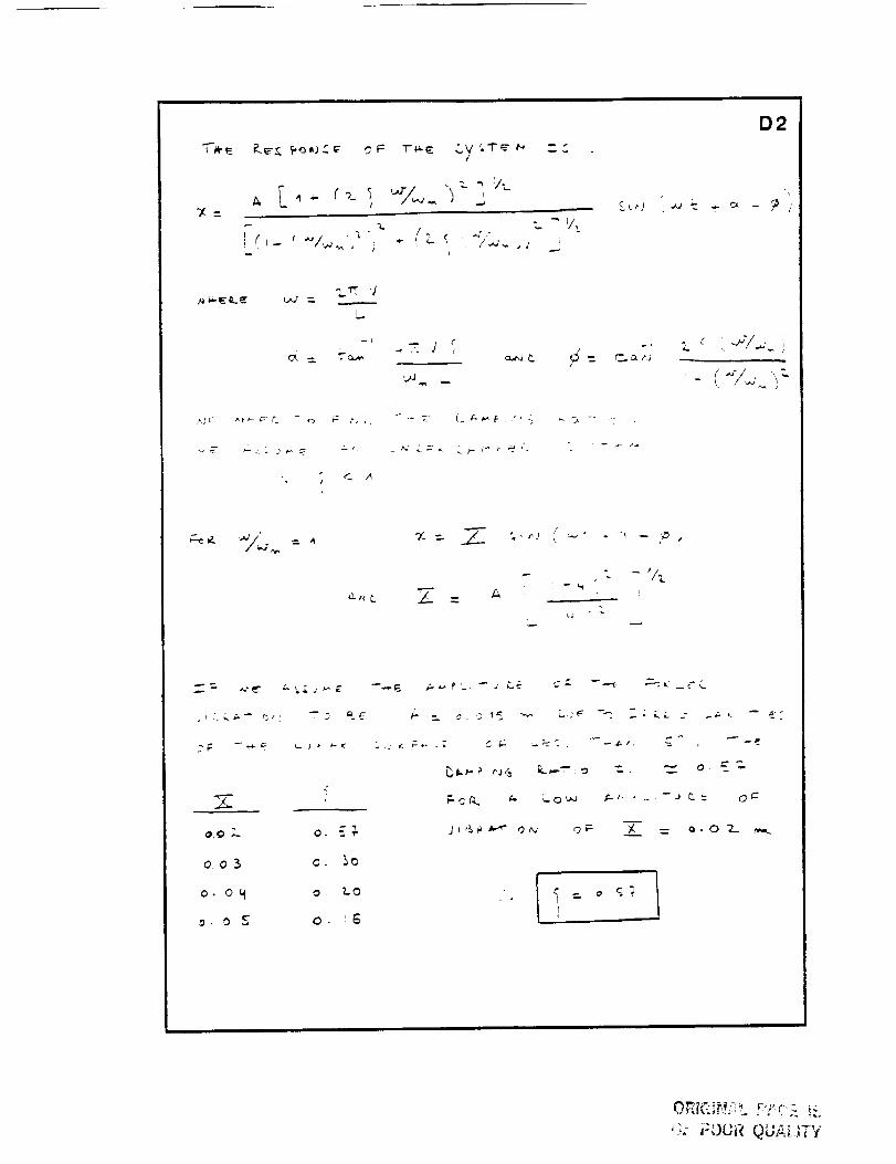
Due to uneven track sections, an approximately harmonic
excitation occurs. Assuming an amplitude of vibration for the SRTV
of 0.02 meters and an amplitude of the harmonic excitation of 0.015
L_
.'Z
Z _ 2'
; Z
2_
7 _ \ .._,_ \,
\
I
/,,!,i2 -i
'l I ,
1
,,\,|
I _ <<,i
< //
: //'
I ,
\\ i
-,\xl
w
Z.
j --
w
F
)-
COZL_
oq<
_JLOW
-F
LJ
Z
b_0
L_
W
3
LL
40
ORIGINAL PAGE IS
OF POOR QUALITY
i i
41
_AA
m
#
\\
T"
_i
_m
1
t
P->
Ii >
,,,']Z _
c_
< £
Z, ZZ
Z Z
3
D
,L3
>
W
U_
W
Z
WZZ_
L©
U3
W
> rr
Z -T
rr
P,I
L]C_
L_
ORIGINAL PAGE IS
OF pOOR QUALITY
42
meters, a damping ratio of 0.6 is required. The damping ratio of 0.6
causes the vehicle to reach equilibrium quickly, therefore enhancing
the precision of the robotic arms as they lower and raise track
sections.
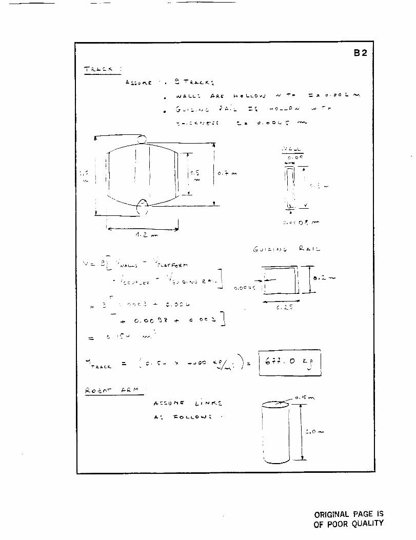
Robotic Arms. Two robotic arms are used to lift and lower the track
sections between the ground and the platform above the cargo bay.
The arm on the vehicte front lowers the track sections to the ground,
while the rear arm raises the track sections from the ground. Both
are configured the same way and follow the same motion of travel,
providing the versatility of forward and backward motion.
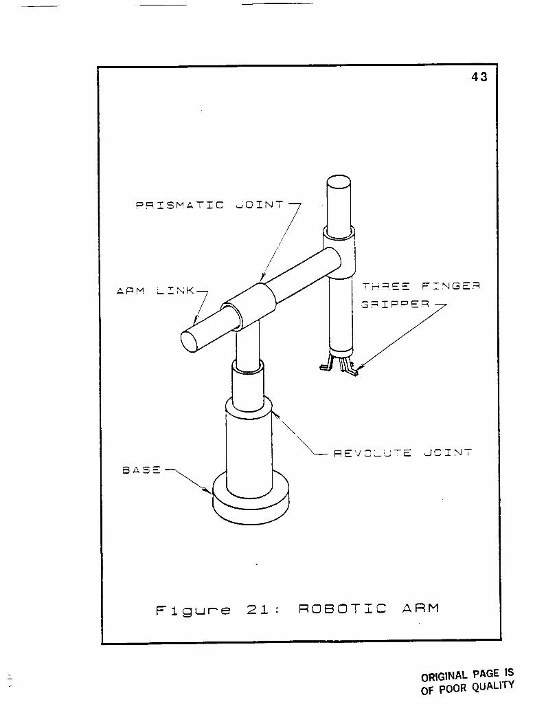
The number of degrees of freedom required to lift or lower a
track section between the ground and upper platform is five. Each
robotic arm consists of a base support, four linkages, two revolute
joints, and three prismatic joints (see Figure 21). Precise control of
the arm is achieved through high natural frequency linkages by
using materials with high stiffness.
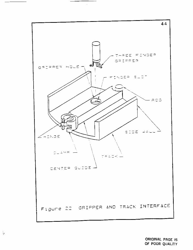
At the free end of the robotic arm is a three-fingered gn-ipper
which grasps the track section for travel between the ground and
upper platform (see Figure 22). The three fingers of the gripper fit
into slots in the track section center and expand. With a vehicle
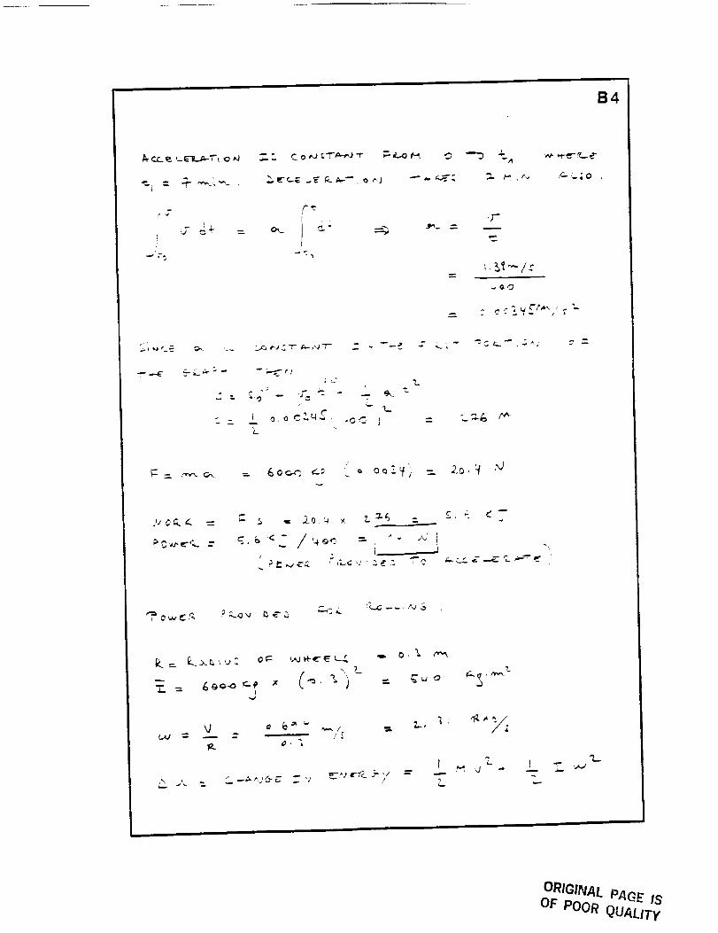
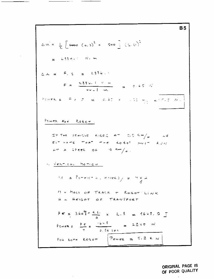
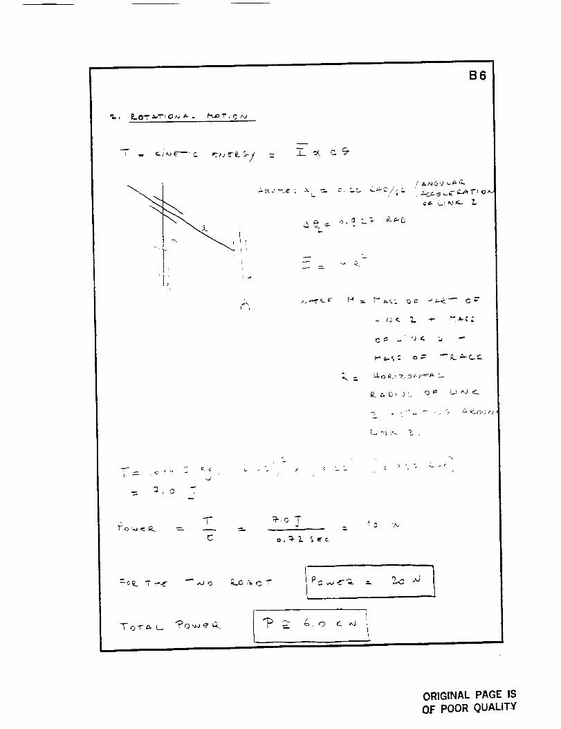
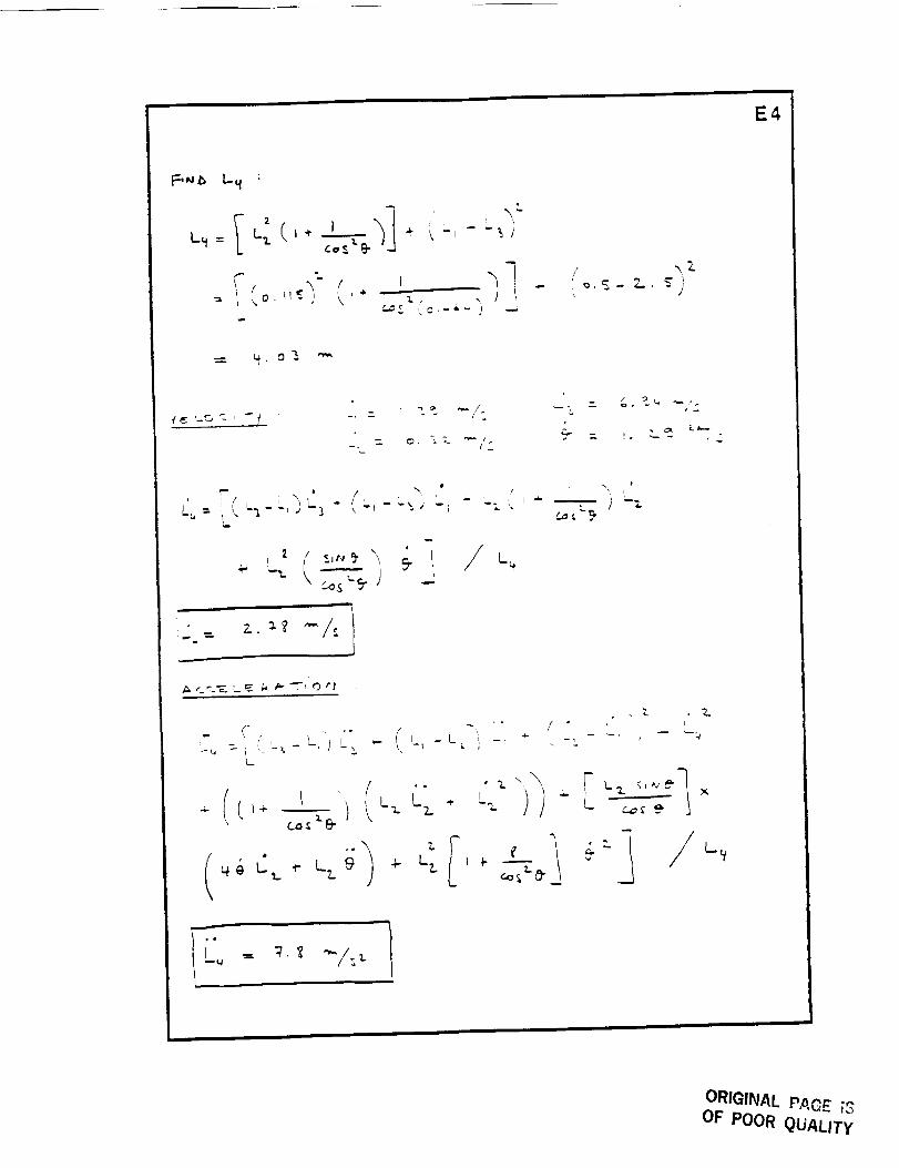
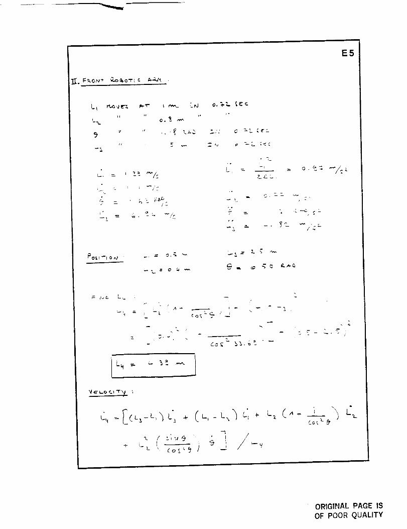
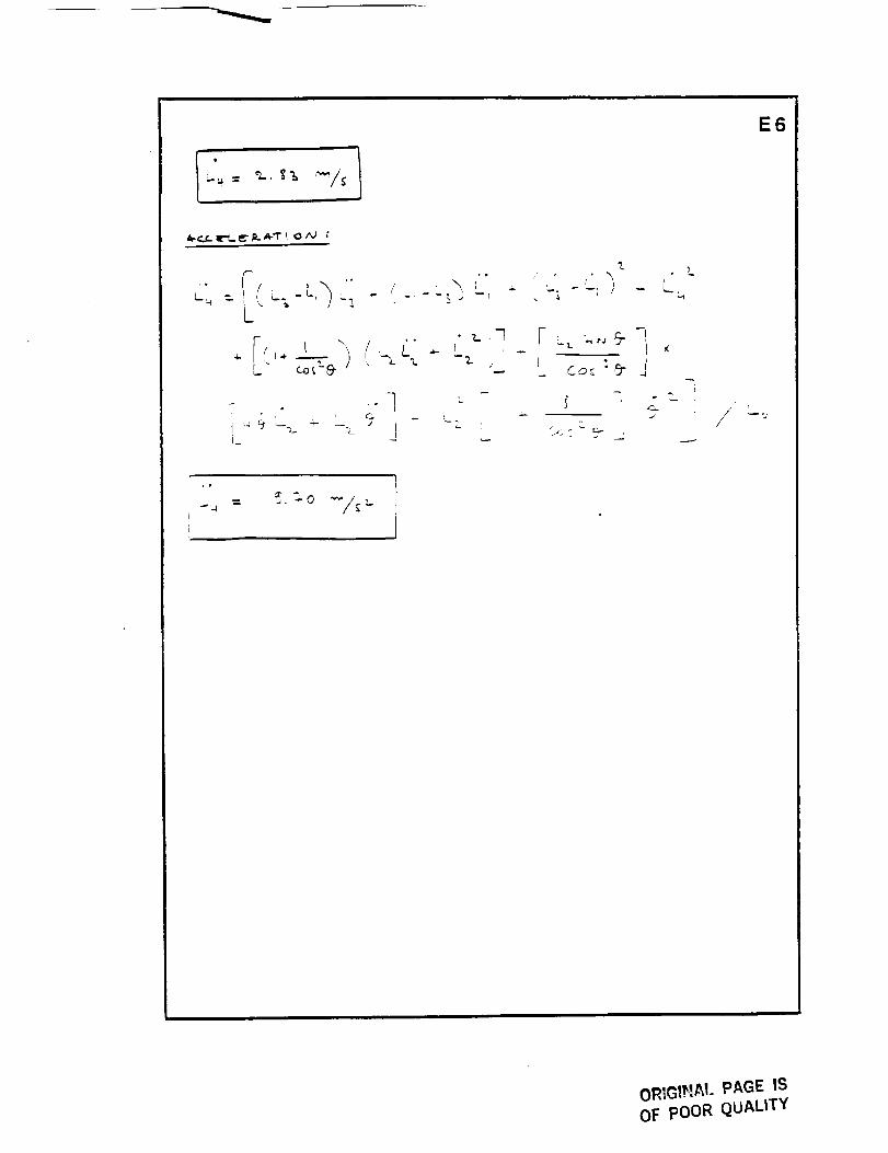
cruising speed of 5 kilometers per hour, the robotic arms will. raise
and lower the track sections with an average velocity of 2.8 meters
per second (see Appendix E).
The motion of the robotic arms is controlled by an on-board
computer. The repetitive motions of raising and lowering the track
oRIGINAL PAGE ISOF pOOR QUALITY
43
\_ _E"/QLUTE dO!NT
Figure 21 " ROBOTIC ARM
ORIGINAL PAGE IS
OF POOR QUALITY
i
44
\, \
\
\t \,
G_iPPER _NO T_ACK INTERFACE
ORIGINAL PAGE IS
OF POOR QUALITY
45
are pre-programmed while any unexpected motions, such as locating
a misplaced track, can be inputted into the computer from
teleoperation signals.
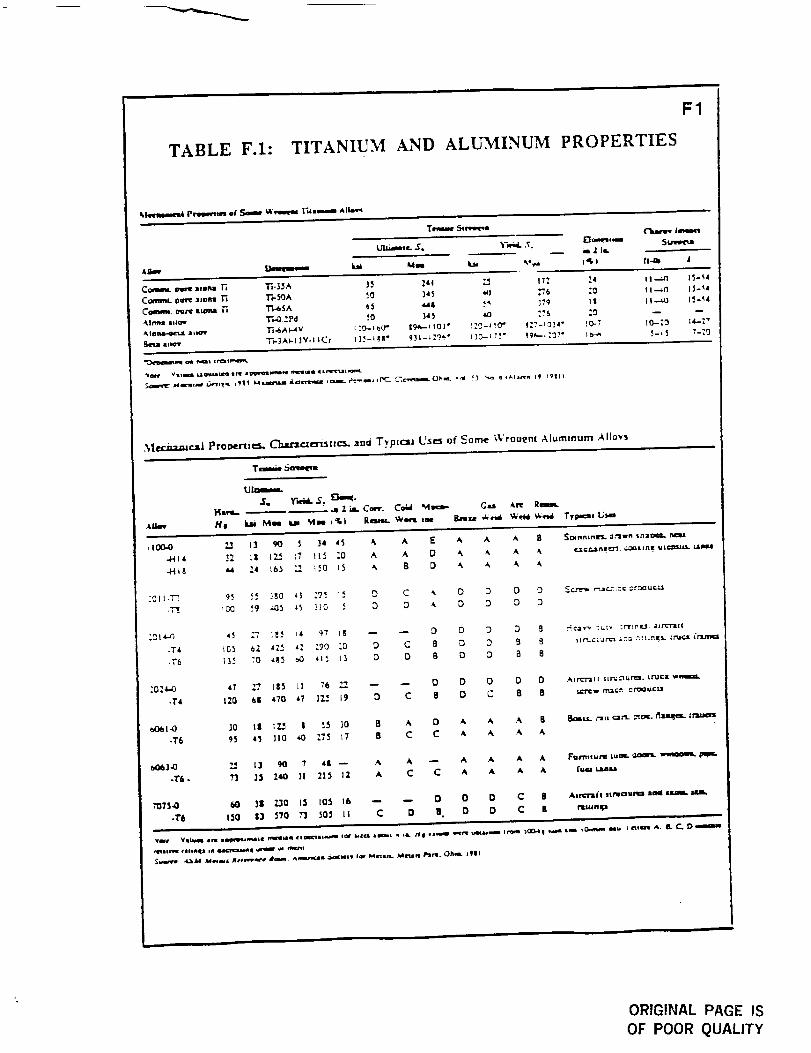
NIf_terials. The team chose titanium for all structural members,
robotic arms and the tracks. Aluminum is used for the shell of the
cargo bay. These two materials are chosen because of their high
strength to density ratio and because they have been successfully
used in previous NASA space craft.
Titanium has favorable ph-'sicai properties such as low densit':',
high strength, and high stiffness which makes it preferable for
supporting structures, but is difficult to machine and requires an
inert atmosphere for welding. In the lunar environment where
temperatures vary from -171 degrees Celsius to +111 degrees
Celsius, titanium is an ideal material because of its tow thermal
expansion and good high-temperature strength (see Appendix F).
Aluminum is light weight and high strength but lacks the
stiffness required by supporting structures. Therefore, the team
used it only for the cargo bay's shell. Its low coefficient of thermal
expansion and adequate temperature strength are appropriate for
the lunar environment.
Tel¢gperation. The SRTV can either be teleoperated from the lunar
base or from earth. Two methods of teleoperation are currently
under study at the Jet Propulsion Laboratory in Pasadena. California.
48
The two teleoperation methods are Computer Aided Remote Driving
(CARD) and Semiautonomous Mobility (SAM).
With the CARD method, the SRTV continuously receives travel
maps from earth. The speed of the vehicle can be no more than one
cmzsec. The vehicle response to operator commands lags by 2.5
seconds because of the earth-moon distance. Therefore, since the
operator does not have instantaneous control of the vehicle, the
vehicle speed must be kept low to protect the system from striking
dangerous or destructive objects.
The team has chosen the SAM method for teleoperation and
course mapping for autonomous operation of the SRTV. The
sequence of operation is as follows"
1. An orbiting vehicle produces global topographic maps of anarea of the lunar base and sends them to earth.
2. On the global topo_aphic maps, an operator designs a path
and identifies locations of dangerous areas or
obstacles to steer clear of.
3. The global maps and paths are sent to the SRTV's computer
which combines them with its local maps to torm a revised
map.
4. The computer analyses the revised map, determines and
records a safe path for the SRTV to travel.
5. The SRTV travels a short distance before receiving another
signal from earth.
6. After completing a course, the SRTV operates autonomously
following the same course until a new one is specified.
ORIGINAL P/IGE IS
OF POOR QUALITY
47
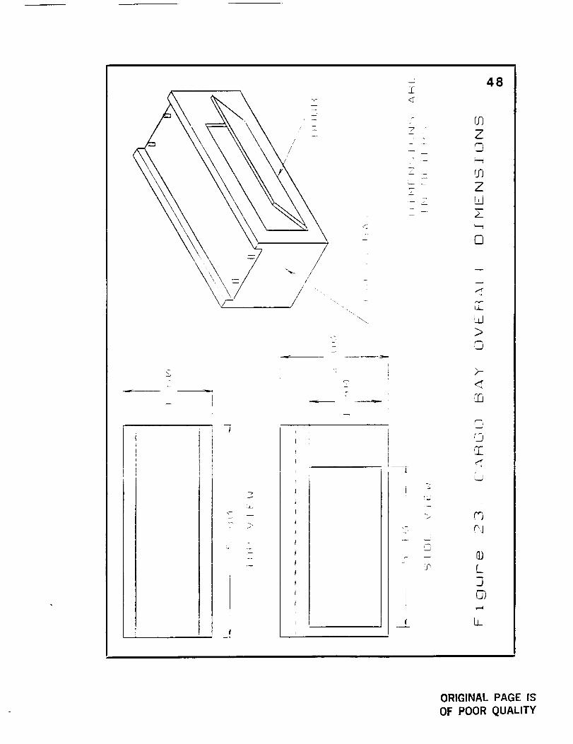
Cargo Bay Dimensions. The dimensions of the cargo bay were
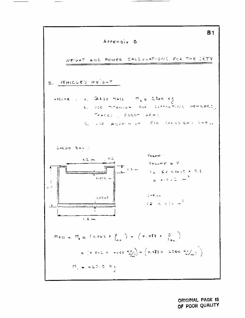
determined by the SRTV's maximum payload and size of the cargo.
The team set the SRTV's maximum payload at 2500 kg and the
maximum cargo size for cylindrical cargo is 1.3 meters in diameter
and 5.0 meters in length, and for rectangular cargo, dimensions are
1.2 meters in width, 5.1 meters in length, and 1.4 meters in height.
The cargo bay dimensions with these specifications for cargo are 1.6
meters in width, 5.8 meters in length, and 1.6 meters in height (see
Figure 23).
gOMPARISON WITH L[,,_'NAR ROVING VEHICLE
The SRTV is designed to replace the lunar roving vehicle (used
in Apollo missions) for cargo transporting within the lunar base. A
comparison of the two vehicles follows.
Criteria
Mass _loaded)
Manpower Required
Power
Personnel Safety
Teleoperation
Cargo Capacity
Rover _RTV
708 kg 6000 kg
YES NO
3.0 kW 10 kW
Good Excellent
Difficult Simpler
500 kg 2500 kg
The primary reasons for replacing the rover are to reduce the
chances of astronaut injury and allow them to do more important
tasks, which are strong points of the SRTV.
/=
_J_
J
!..L_
:>
3_
_C
,m
7
.'T-
J
__L
48
fj--jZ0k.--t
rj"]ZW
ID
I
i
.,,,,r
L.d>
©
2"-
©
r")r_j
Q)
L
L
ORIGINAL PAGE ISOF POOR QUALITY
CONCLUSIONS AND RECOMMENDATIONS
The Self-Repositioning Track Vehicle was chosen not only
because of its superior benefits over the other design alternatives,
but also because it was a new and novel idea that has been
researched very little up to this point. The following characteristics
show how the design has met the specified design criteria:
1. The SRTV requires no manpower for operation so the
chances of injury are reduced and the astronauts are freed
to do more important tasks.
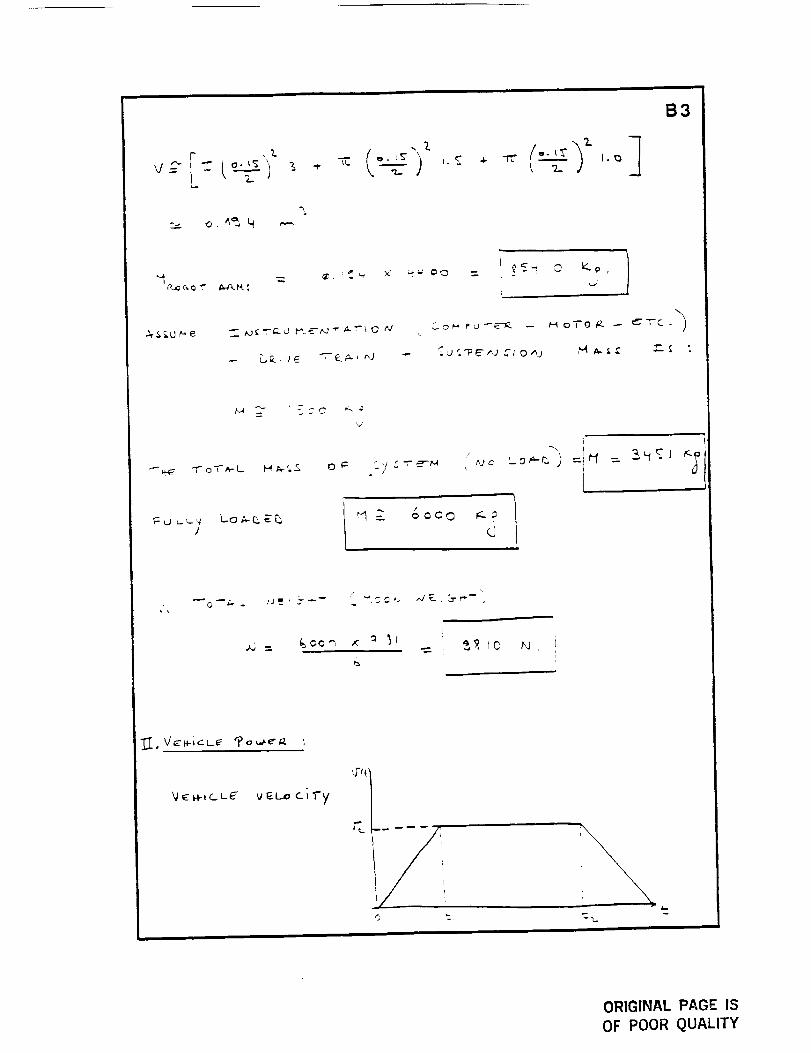
2. Empty mass of the SRTV is 3500 kg and fully loaded mass
(vehicle and payload') is 6000 kg.
3. When fully loaded, power needs are approximately 10 kW.
4. No system disassemblv or assembly is necessary upon
relocation to other facilities in the base.
5. With a maximum payload of 2500 kg, the SRTV travels at a
top speed of 5 km/qnr.
6. The cargo bay has dimensions of 1.6 m by 5.8 m by 1.5 m
for a cargo volume of 14 cubic meters.
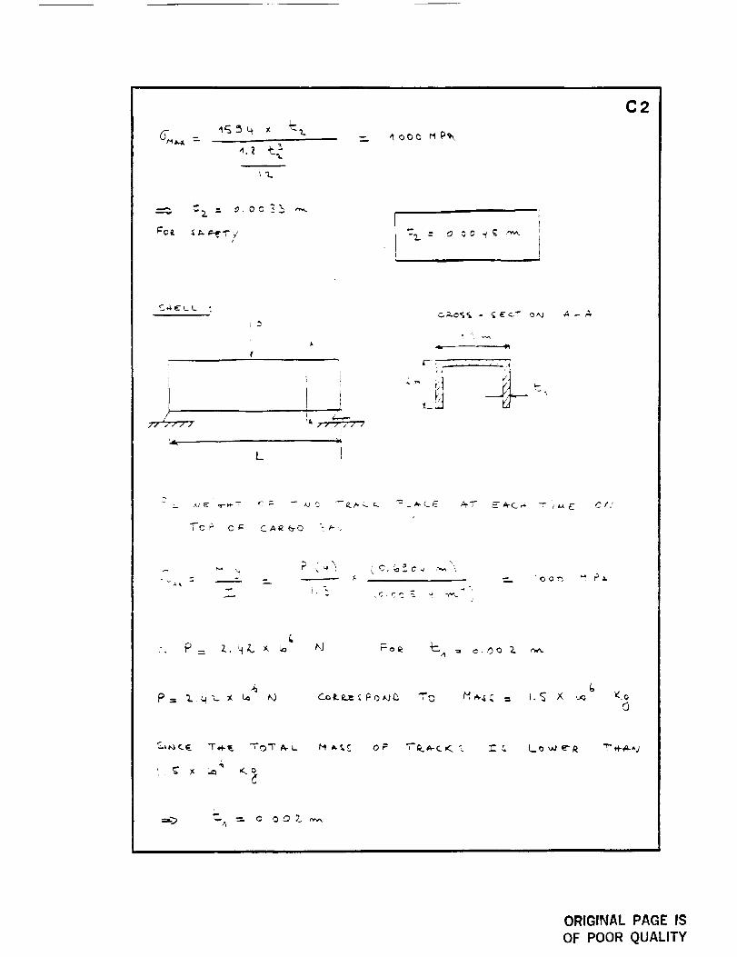
7. The cargo bay structure is made with titanium as confirmed
by stress analysis.
The team has concentrated their design efforts into six areas:
track connection, vehicle/'track interface, robotics, materials,
49
ORrG[_!AL P,_GE ISOF POOR QUALITY
50
teleoperation, and cargo bay dimensions. The team recommends
further design and investigation into other areas.
The present system design assumes operation over a flat
surface so that track sections are flush with one another. Further
investigation should be made for operation over rough surfaces when
the track sections are laid unevenly.
Use of high-strength, low-density composite materials will
reduce overall vehicle mass and power consumption. The team
recommends the use of such composites as they are approved for
this type of application.
Lunar dust is abrasive and conducive to rapid wearing so all
joints connecting moving parts must be protected. A device must be
designed to remove the sticky dust from the track section undersides
without creating a dust cloud over the vehicle.
The robotic arm operates quickly to lift or lower a track section
between the ground and upper platform above the cargo bay. Thus
the point of application of the robotic gripper onto the track must be
quickly and easily found. A honing device is needed so that the
gripper can locate the track and define its orientation when the track
is in any position on the ground.
Finally, the team recommends design efforts pointed towards
serviceability. Although the vehicle is designed for reliability,
maintenance and repair may be necessary. To facilitate the repair of
the SRTV, components should be of a modular design for quick and
easy removal and replacement.
REFERENCES
1. "Advanced Composites", Sept./Oct. 1989, Vol. 4, no. 5, pp. 34-35.
2. Budinski, K. G. , n.n=meermg Materials - Properties and
Selection", Third Edition, Prentice Hall, 1989.
3. Gere, J. M. and Timoshenko, S. P. , Mechanics of Material_, Second
Edition, PWS Engineering, Boston, Massachusetts, 1984.
4. Juvinall, R. C.,.Fundamentals of Machine Component Design. John
Wiley & Son, New York, 1983.
5. Meirovitch, Leonard. E!¢mcn_ of Vibration Analysis, Second
Edition, McGraw-Hill. 1986.
6. Mulhall, B. E. and Rhodes, R. G., Magnetic Levitatiora for Rail
Tran,sport, Clarendon Press, Oxford. 1981.
7. "Lunar Surface Transportation System Conceptual Design", NASA
Contract NASS9-17878, July 7, 1988, (NASA-CR-172077).
, Wilcox, Brian H. and Gennery, D. B., A Mars Rover for the 1900's,
Robotics and Teleoperations Research Group at the Jet Propulsion
Laboratory,, California Institute of Technology. 1989.
51
APPENDICES
APPENDIX A
DECISION MATRIX
A1
ALTERNATE DESIGNS SELECTION BY DECISION MATRIX
The team used a decision matrix to select the best design from
the seven alternatives. The team generated the fifteen most
important design criteria to judge the seven alternate designs.
Weighting factors were assigned to each criterion with the more
important criteria receiving a higher values.
The weighting factors were obtained by using the method of
pairs which compares every criterion against all the others with the
more important of the two receiving a mark. The number of marks
are summed and divided by the maximum possible number of
marks. This ratio is the weighting factor.
The designs were compared under each criteria and were given
a number from 1 to 10 (best) according to how well they satisfied
the particular criterion. This number was multiplied bv the
weighting factor to obtain a certain number of points. These points
were added for each design and the totals compared. The SRTV had
the highest number of points, indicating it was the best alternative.
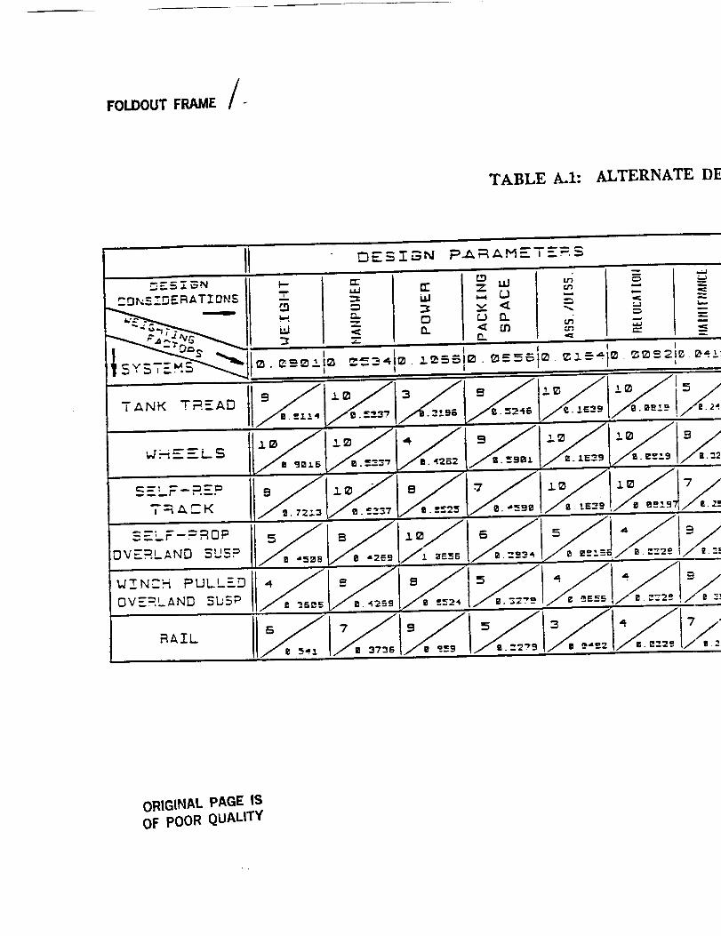
FOLDOUT FRAME /-
TABLE A.I: ALTERNATE D]
II DE5I_N Pi_ Z_METE:, $
ORIGINAL PAGE IS
OF POOR QUALITY
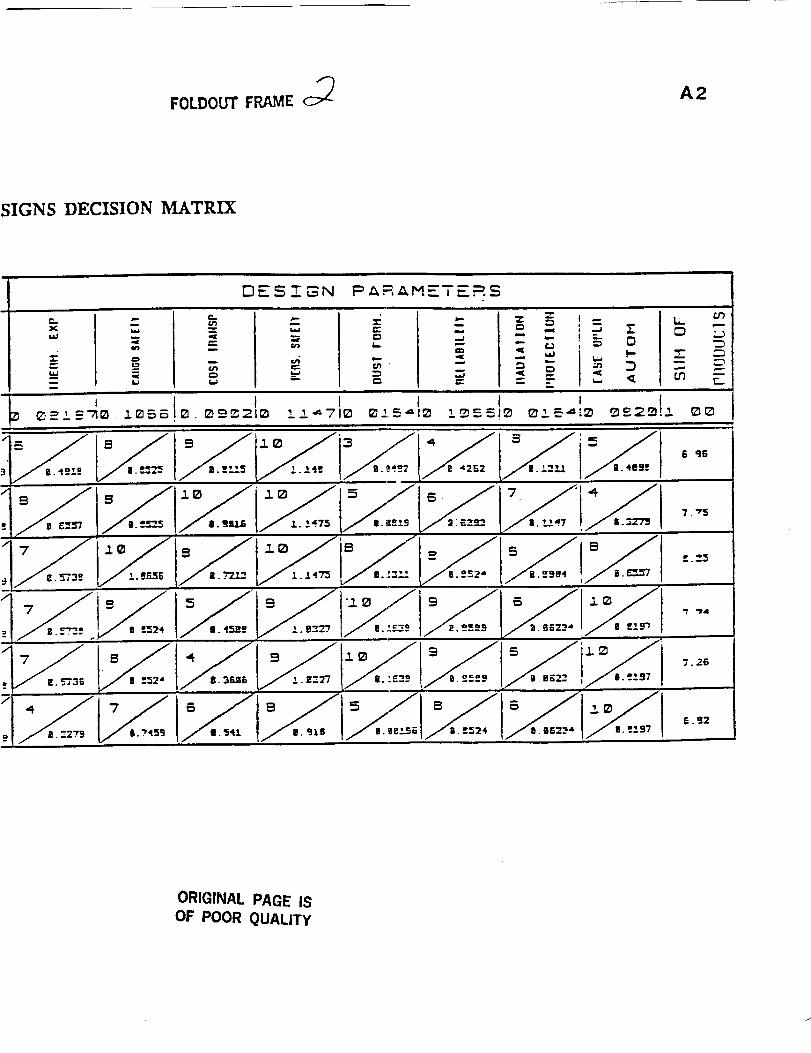
FOLDOUT FRAME c_ A2
SIGNS DECISION MATRIX
DESZSN P AR,_,M='T E=.S
¢.xi,,i,J
I,.i,J
-g=_
l.I
,?.=
U3
__ =
, !
6 q6
7 °
V I..J. 4"_
/!. L£--._
7. "_5
£.'_5
"Pall
7.26
_. _2
ORIGINAL PAGE ISOF POOR QUALITY
APPENDIX B
WEIGHT AND POWER CALCULATIONS FOR THE SRTV
APPEM_i_
B1
I
&
,If'-
s C C .T.
r'1 = H__,_. C ,Ko, ,j
r.._
OR!GINAL PAGE IS
OF POOR QUALITY
B2
• v,,,'ALL'.. ,_-_.&" _ • LLO',,,J _' --J"
i l
J
a. 2___,--
i ._.'S
L
©. C)'C
: ,i
!r
: il
J
/
-.- o,oo q_ iL,
ORIGINAL PAGE IS
OF POOR QUALITY
f ,l.÷
.l
TC I °" !_"
B3
_ • Z- 5, ,.. ` ,:.. _
L,'
]
' "i y
C
-_ $! _c
&
6-
ORIGINAL PAGE IS
OF POOR QUALITY
f
B4
_ _ "r"_- 7¸-'_'- ,,,ill I
C_'tti ,_ L
p,3
,fs
;._,-/-"
"L%
Ze)' LJ
+? 0_; _
"_. = _ g°_° _'_
_jlll lll
I1._ t
%..
ORIGINAL PAGE IS
OF POOR QUALITY
B5
.[_ L.L ='C i k *--. _1
.i.
/
, .4
i, ,i
?_ _e'-rk _ le _-0 E. C, _ "
E
,y"r %.0
/ •
5 _ 0
/ d
=- ALe'-_ G ,q'-T 0 7- "1" I_._-,v -_ P o _--r"
PC_v.-_ : P ;
x 2.,. _J .--- '1_,_',6
Fo£ &o "r,,4- _..,0& o"_
T..,J
ORIGINAL PAGE IS
OF POOR QUALITY
B6
_., _'r _T_ _ _ a. _. _ 1"_ C ,_a
i
i
12
_ _-_L O_ _'i.-_ C _"
Pc ,,_z-& --- _ vJ 1, - - i, i
ORIGINAL PAGE IS
OF POOR QUALITY
APPENDIX C
STRUCTURAL ANALYSIS OF THE CARGO BAY,
TRACK, AND TRACK CONNECTING JOINT
ORIGINAL PAGE IS
OF POOR QUALITY
APPEN b_ x C
Cl
.,=_C
Y..,V :_ "-.j F c r !:-"-' ,'- t,,:
i!
r , ,,
.l:..c..': ;.:.ll/l_; " ,
JJ
_: _. ;./-4 ET
I i
L
_,'_& _,_¢,,,.,+,,jt4 4" _ A
d....,... , , ,',/ .. "'," ,' ',' ," . ,,..... ....... ,. . :_j
o"_,.x
r_
"T"
W L." m =
%
4_
ORIGINAL PAGE ISOF POOR QUALITY
;'L
_..., ,,,,l
, r
C2
i'
Ii
// ..,ilj J rlk /z i / f
'4.. "l (
L I
... p = z. _ _ t_ _ ;o_ "_---,,_ '= ,c. OC_ 2.
4P-,_ "L.q",.-x _ t,,,) _'.._t.e,,_:_l::o_l_ "70
G
1, _' _ _ V..,._,
"_ & L_ w e'R m,t-_-^j
ORIGINAL PAGE IS
OF POOR QUALITY
C3
I
_OQm MP_
_ O, Oo _a
Fz_K _-__ T/Yj _31 _) rr H_ _ E
ORIGINAL PAGE IS
OF POOR QUALITY
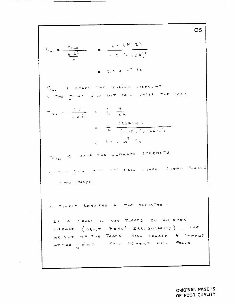
T'I__ ,¢.-c. it.., C o r_ eo E" c_ 1"-_ toG-O I'_ T"
C4
'!
L
_ _L_ CO _ t_e -_ _%_
F
?c
/
I
!_ o = c.'_ _
0.06_ ,',,.,
_I-o_-_- L- _T o_-
-. P_ o
V= _P
= - P "Z. )t 0 %
ORIGINAL PAGE IS
OF POOR QUALITY
C5
,<-. I"t _,i_
co
,,..,.
,A
.'U" , e, r-.._ L. c, _ --_
,,/2__,:I.-Ir7 l
',,..!,l_. l,.. I:. "i" _ r.,. _ t._t _ _ 1"_r _, "T _ _ "_ _-_" t"1"
_ .+.._, ,.._s,,_ _ ,
..J-'.4- _ _",C _-_'_J'/_ _jI _._.
ORIGINAL PAGE IS
OF POOR QUALITY
C6
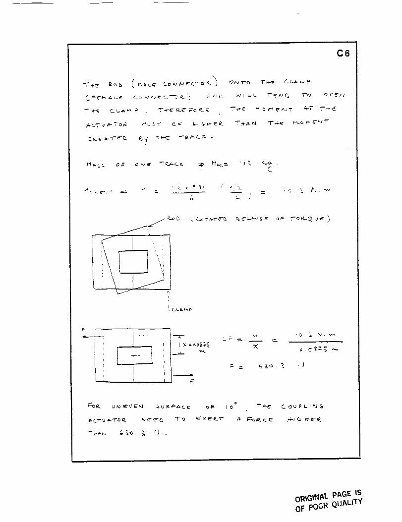
/
/
'_#IL.L T__-_vP_ "i-0 o PEr/
C
" "c. I _ _'_ / ,4'
& : Jio. Z #], _"
b
I !
F
6&o.
-_ _,_ . _ _J
o
_o
A-
ORIGINAL pAGE IS
OF poGR QUALITY
C7
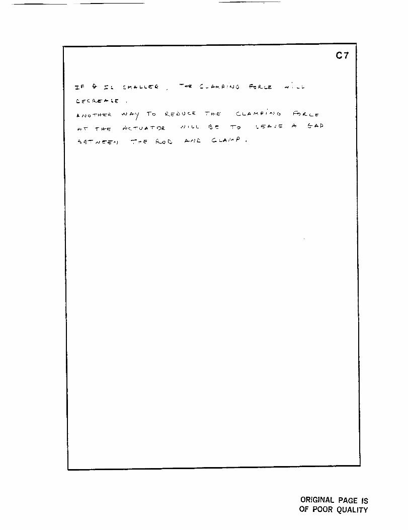
£ j_jo -r-_E T'd-E CI-A _ P J ^,_ G
ORIGINAL PAGE IS
OF POOR QUALITY
APPENDIX D
VIBRATION ANALYSIS OF THE SUSPENSION SYSTEM
_PP_j x D
DI
_" _ r "_'_ q ,. -- " L _--'E
4j
,.
!.,-., ., _. 1"_ _ _ , "," -,<,,./'
r
C -
I_._. 1", 0 =r.
i-
ORIGINAL PAGE IS
O_ POOR QUALITY
/
r "u I.. _ !/_
D2
\,
___. 'J
-_ .je--_ __..arJ
A
o.0 2.
oo3
o.o_
_.o_
o E_-
o. ?-.0
c¢- -.-.c _,: __Q
/- -- s. .; 4=. _ L;e- -_ " i ,.- ;...
r-Cf_. _, ;-o _',a
o,=V.
= o. 0 _._ t)-,._
.. _(..,z4,,_T ¢
j
-j
D3
o
c = .16,_ _" _,
J
^
, "I ,c.=_.. ._ > _
_T
i
X _,o_
ORIGINAL PP,GE IS
OF POOR QUALITY
D4
Mo_e _.
' ' 1
i_ _
?i
/
t 1x /
ORIGINAL PAGE IS
OF POOR QUALITY
D5
,. P L _
3E_
L•.A
aL
_ I<. 9< "- 0
0 _f. /_
i
i
I 0 I6,.,.
!
L
ORIGINAL PAGE IS
OF POOR QUALITY
i i
o
o
i'_.t
C
C
(-,,Q
0
_ __..._v
0
0
0
0
D6
0 0 0 0
0
©
t 0
0J
Q
/;
ORIGINAL PAGE ISOF POOR QUALITY
D7
J
,/LX,w '
7"
at
j'
/
/
(_O,_c_u-O _o,',a
_"I" A. "r;_,a _ ,,.j-r"c,v..','_.,- ¢= _,':?_ ._e'-c.
"F'.H-C__EA.,VC "T-a--_-I • 1
:,,QE/
oRiGINAL PAGE IS
OF poOR QUALITY
APPENDIX E
KINEMATICS ANALYSIS OF THE ROBOTIC ARM
ORIGINAL PAGE ISOF POOR QUALITY
PP_,v (bix E
El
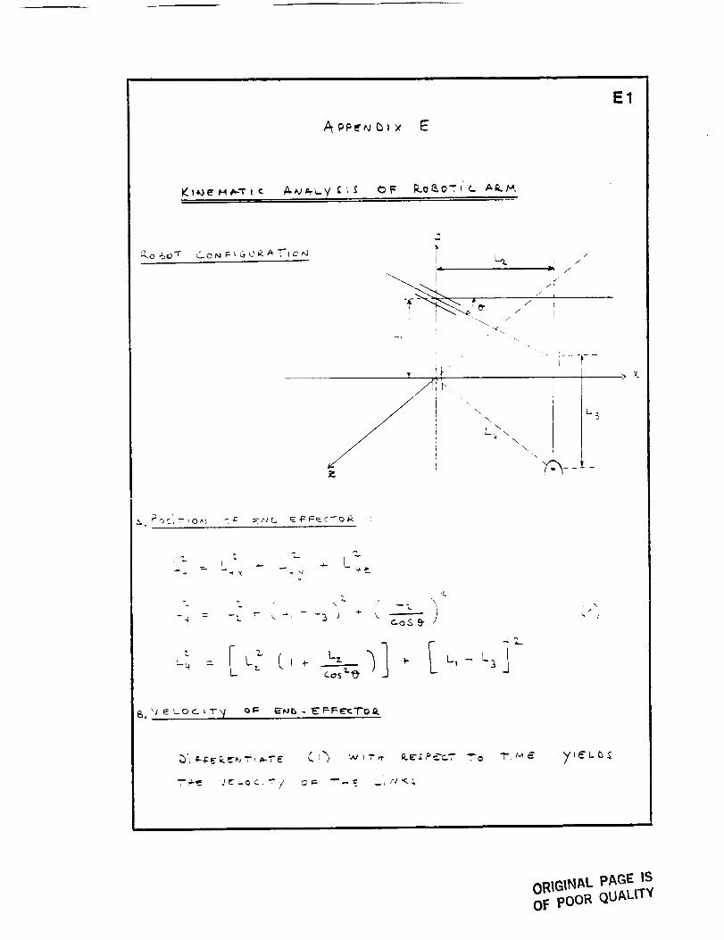
_7....C. _ _ "F _.. 0 N F- _ G- 0 P. _" ,'[- I 0 ,"J !',1[
--....
R_
./
/
/
\
\.
L_ ,_ \,.f \
.\
L_
_.. Poc' R-,o^) c¢ E_.,,c.. E-F_EC_TOG. :
_" I " I _'L..
=- L._ X _" ' _"
-%
Lq = LL C I -t- cos_
ORIGINAL PAGE IS
OF pOOR QUALITY
1=2
t_ L
r ,
dL-,
I
-- O'
. I '
:(L.,_L ') _.L, _ __(,_ -L_'"; ':':' __, _L,,
_9- - 0
I
, __ : .,v i ,"r,-, _._-_ T--_--_.-- _ _ _ '/ "- &,U
(_,- L,] i\, _ ( i_,
A
! /de de;
_ _o- de" \ _I. t 1 _J
ORIGINAL PAGE IS
OF POOR QUALITY
F"
A "_
l
/ , \\
E3
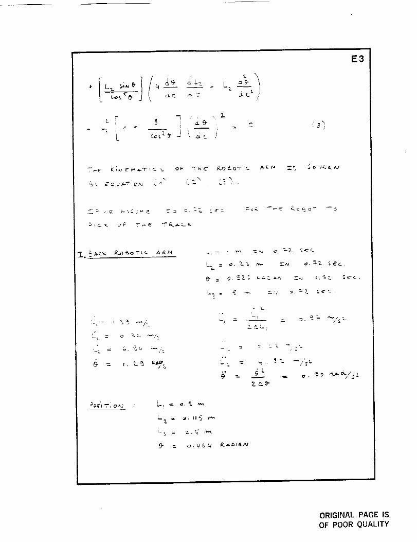
'-" 14-_ K __ _- _, A.--I- t _. %
%
_, _,_ j_.'t'. ',0_ _ _ k. _ z •
:_, = _. _. "_ _,_ :'w _. =-2. _; _..
,_ = _. _ _,_
%"° I
L_L
.._ _, _0 xt.._,,_/'_.Z
r_"_ "r'i a ,,,3 ,
ORIGINAL PAGE IS
OF POOR QUALITY
E4
L_= L_(I+ I-!----
I
_L
+ _- --_
/ -,2,
= _.o_
c. \ ?_ "-/-L t
i .
+ q (,-,_>"___._ -_ .7
" "° ic Li_ - ,
+Ii+--' (
_ L I _ "--'-m--.) --i
,
.,L • 2_
_L+ --' )I+
L L I i- _._.
ORIGINAL P,_G_ ',-
OF POOR QUALITY
i ii
E5
I II
ii
ii
v
_p
• %
/=2_._ ,
I •
._ /"S
I"O_,l-,t,-i o _ , _, _ _,_
J
/
------T--{
\
_.¢£/
Lot _
ORIGINAL PAGE IS
OF POOR QUALITY
EB
' " f L ' ..,. f _, \_ t
-G L
i
't L
L L _ r.s r_ Co_ " ,9" ._
J
i
]
OR'IGI!!AI- PAGE IS
OF poOR QUALITY
APPENDIX F
MATERIALS PROPERTIES
F1
TABLE F.I: TITANIUM AND ALUMINUM PROPERTIES
_hMNaeamr_¢ PT_mn'._ oe"._ _',mul.m ]'_4neNI _lto',r',_
a_m k._ _%,J t '% | [l-tb J
.Meciuuuc.=J Proaeru_. _ctm-tsz=c_ =ad T.vplc_J Use_ o( Somme Wrou£nt Aluminum Alloy5
T_i_ 5o,_e
Ulln_mm.
$o Yk_. 3, O=,,q.Hmm-. _ _ Z ;- Corr. Co_d ',4_a-
_,llkw He km Mm '-, Mm _) Rest. Wm ,m B_ •A'tqd _'t,,kl Wesd Typ*¢sm U_e
100-0 1.1 13 90 _ ]4 45 & A E A A A 8
4414 ]2 11 t2_ I? tl_ :O A A D _ A A A
-_¢g 4,4 Z4 L65 "_ t._0 15 A B D A A A
_Daf_lnrJL. G.'_Iw_ 5ftlt3_$.
r..lc_..,3nf_ _Llrta_ UL_"_tJUt. _ILOULIJ
-i"S
D C *, O D D D _c,"_,,,-t_tc:.;:c :rcmu¢.._
D D _ D D D D
•T6 13_ T_ _s_
i'L @7 -- -- O D D D
D C 8 O O E] 8
D D B D D B B
_1-O 30 It 12_ I _5 30 B k D A A A 8
•T& 91 45 310 ¢0 275 t7 8 C C A A A A
i_LL r'Ji. (=l,r_L _0¢. t_JI+iU_'CL4'r'Ji_
-r6. ?3 J$ Z40 31 ZI5 IZ A C C A A A A tu_ t,ta_
7075-0 60 )11 LI0 I_ I0_ 16 -- -- O O D C il Amra'sil sln_nvm asl _ tts.
-T6 I._0 l) ._70 T) ._O'J I l C D II. D O C II ru.n_
ORIGINAL PAGE IS
OF POOR QUALITY
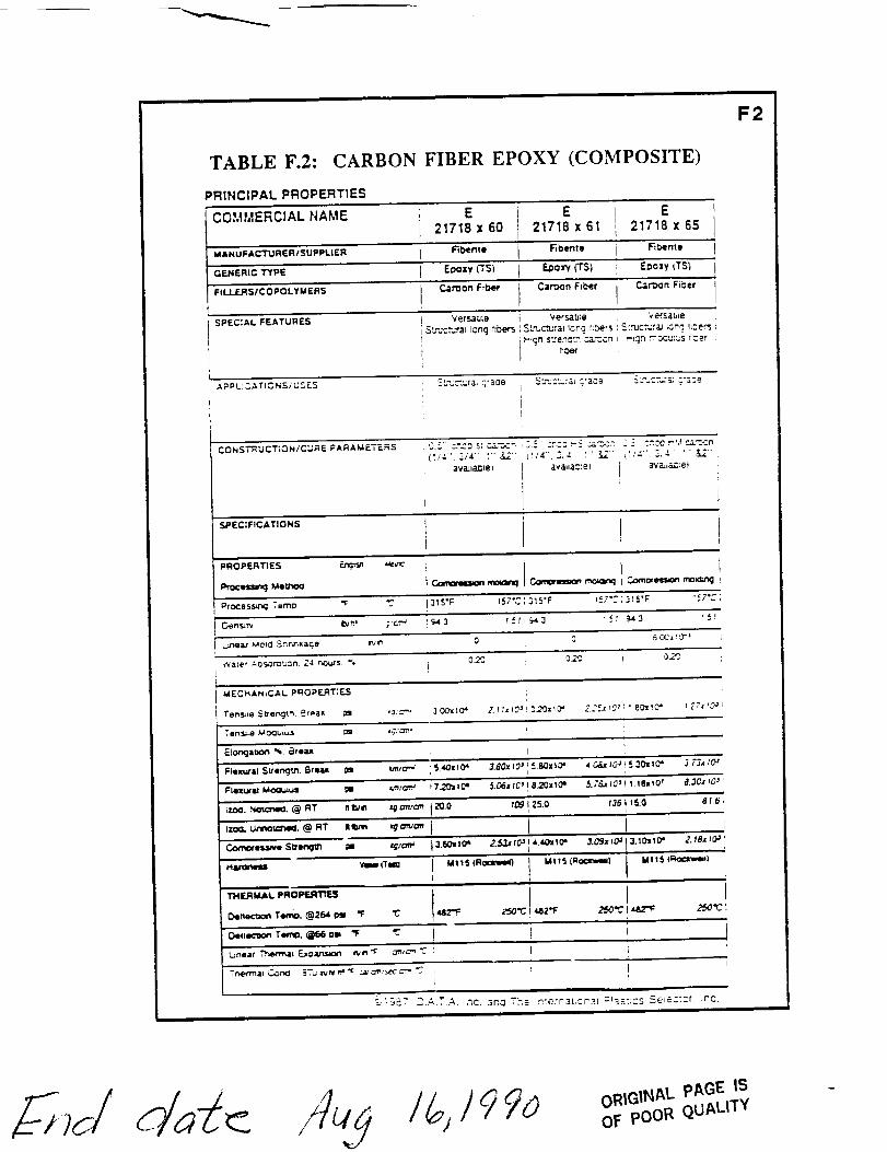
TABLE F.2: CARBON FIBER EPOXY (COMPOSITE)
PRINCIPAL PROPERTTES
COMMERCIAL NAME E E E21718 x 60 21718 x 61 21718 x 65
MANUFACTURER/SUPPLIER F_tb,erRe _bQnte _ntff
GENERIC TYPE E_oxy KS) E._oW (T5) E=ozy (TS)
FILJ.JE.RS/COPOLYMERS C.art_0n F;.i_ Cart)on FiDer I C_.,"_n Fi_erI
SPEC:AL FEATURES Vet_u;e Vers<lb; ,= Ve'rsable
SLmc%_rat Long _:_ Sl_uctura= _c_o_ {;pets S_rucr,;r;u ;cn__ _Lcers :
hDe_
APPL!:'.._TICNS,'USES SL%_,-Ja_ c ra_e S:.'J:3.:,_ _r3ce _..".cT..-'_ C"23e
CONST!_UCT;ON/CLJF_E PARAMETERS 0.:_" :r_.3 S: _--,.,C_ C._ C:_C.3 "-': ,.:.&T-.3" ._ _, :.',_0 ."_,! ,c_--'_cn
_vaJtG_el av_lc3_':e_ ( _2"va.,.;r:eti
SF'ECI,.CAT,O.S
f'.OS'ERT.ES _ '_'= 1 1 i
Ptocesscbg TomO "1: "Z. 315"F _57"C ; 315"F 1_7": ; 315"F ;57"_ ;
C,en s;rv _,= ,:,,r..,_ _3 _! r=,43 ! _,' ' 943 ,_!i
t.me_" Mold Snn,n_ac_o _v_ O g _ CC= 1C'=
'_ale," ._=s.._,"_c,n Z4 _',.. % 0_'C ,3._2 ! 0.2"2.
MECI_ANiCAL PROPERTIES
Eio_aaon %. ¢3,ea= l t
FNIm..'I¢S.'engu'_, 8rea_ ;Is _m_'.,m'_ i S._:_=tO" 3.80x t2_' ! S._x tO" ,_ O¢_ tO J ! 5,30= ,0" j 73., tO_'
17._. Not_'wm.@RT _!1_/_ _mv/_r r20.O 709 ;'5.0 13_llS.0 816,
IZ_=. Ut"e_Ic;t',,e_. @ RT Ilium, _m'uo_, I/ /
MI15 (R_
F2
H_lm Yemm_T_ M115 tRocxwm_) MI15 (Ro¢_,m_()
I&82"F
_I-_87 DATA inc..3r',..I T2e nterraI,cnaj "_aS:;cS Se_ez'cr. ,no.iiii i i i i
OF pOOR QUALITY