DESIGN OF A STEERING MECHANISM FOR A PERSONAL …
62
DESIGN OF A STEERING MECHANISM FOR A PERSONAL TRANSPORTER by Yew Kwang Liang Dissertation submitted in partial fulfillment of the requirements for the Bachelor of Engineering (Hons) (Mechanical Engineering) JUNE 2010 Universiti Teknologi PETRONAS Bandar Seri Iskandar 31750 Tronoh Perak Darul Ridzuan brought to you by CORE View metadata, citation and similar papers at core.ac.uk provided by UTPedia
Transcript of DESIGN OF A STEERING MECHANISM FOR A PERSONAL …

DESIGN OF A STEERING MECHANISM FOR A PERSONAL
TRANSPORTER
by
Yew Kwang Liang
Dissertation submitted in partial fulfillment of
the requirements for the Bachelor of Engineering (Hons)
(Mechanical Engineering)
JUNE 2010
Universiti Teknologi PETRONAS
Bandar Seri Iskandar
31750 Tronoh
Perak Darul Ridzuan
brought to you by COREView metadata, citation and similar papers at core.ac.uk
provided by UTPedia

i
CERTIFICATION OF APPROVAL
DESIGN OF A STEERING MECHANISM FOR A PERSONAL
TRANSPORTER
by
YEW KWANG LIANG
8104
A project dissertation submitted to the
Mechanical Engineering Programme
Universiti Teknologi PETRONAS
in partial fulfilment of the requirement for the
BACHELOR OF ENGINEERING (Hons)
(MECHANICAL ENGINEERING)
Approved by,
__________________________
(MR. AZMAN BIN ZAINUDDIN)
UNIVERSITI TEKNOLOGI PETRONAS
TRONOH, PERAK
JUNE 2010

ii
CERTIFICATION OF ORIGINALITY
This is to certify that I am responsible for the work submitted in this project, that the
original work is my own except as specified in the references and acknowledgements,
and that the original work contained herein have not been undertaken or done by
unspecified sources or persons.
______________
(YEW KWANG LIANG)

iii
ABSTRACT
Personal transporter, particularly Segway is gaining its popularity in the
western countries in the recent years as it helps to ease congestion and pollution
problems in cities. However, this is not the case in developing countries like
Malaysia, Vietnam, Myanmar and Sudan as there are not many people who can
afford to buy it due to its exorbitant price. As part of the effort to come out with a
low cost of a personal transporter affordable by citizens in developing countries, the
author is working on designing an effective, highly maintainable and simple steering
mechanism. This project is carried out for 2 semesters, where in FYP 1, the main
focus was on literature review and journal readings to get as much information as
possible in order to design an effective steering mechanism. While in FYP 2, the
main focus is on designing the steering mechanism as well as to analyze its stability.
As readers go though this report, he or she will get to see on how the objectives of
this project is achieved as well as the final results of this project.
iv
ACKNOWLEDGEMENTS
Thank you…
To my immediate supervisor, Mr. Azman Bin Zainuddin who has always
been there to support and guide me whenever I need him throughout the two
semesters. As a lecture in the Mechanical Engineering department, he has always
been busy with loads of work and meetings. Yet, he never fails to lend a helping
hand whenever I need it. I will never forget all the lessons that he had taught me and
I will always bear his teachings in mind for my future use.
To my examiners, Ir. Dr. Masri Bahrom and Dr. Vu Trieu Minh who had
been very evaluating me and give me useful feedbacks thoughout the period of my
FYP project. They have always been more than happy to give comments during my
presentations which serve as useful guides for me to improve my work in the future.
To my classmates, Gabriel Houng Nai Hui and Lee Jin Ming who always
share their knowledge with me whenever I needed them. Thank you from the bottom
of my heart.

TABLE OF CONTENTS
CERTIFICATION OF APPROVAL ........................................................................ i
CERTIFICATION OF ORIGINALITY .................................................................. ii
ABSTRACT ............................................................................................................... iii
ACKNOWLEDGEMENT ........................................................................................ iv
CHAPTER 1 : INTRODUCTION ............................................................................ 1
1.1 BACKGROUND STUDY ........................................................................... 1
1.2 PROBLEM STATEMENT .......................................................................... 3
1.3 OBJECTIVE AND SCOPE OF STUDY ..................................................... 4
1.3.1 Objective .............................................................................................. 4
1.3.2 Scope .................................................................................................... 4
1.3.3 Significance of proejct ......................................................................... 5
CHAPTER 2 : LITERATURE REVIEW ................................................................ 6
2.1 STEERING MECHANISM ......................................................................... 6
2.1.1 Persornal Transporters’ Steering Mechanisms .................................... 6
- Segway & Segway with skiing steering mechanism ......................... 6
2.1.2 Car steering mechanism ...................................................................... 7
- Rack and pinion ................................................................................. 7
- Recirculating ball ............................................................................ 10
- Worm and sector .............................................................................. 11
- Worm and roller ............................................................................... 12
2.1.3 Recumbent trike steering mechanism ................................................ 13
2.1.4 Motorkbike & Bicycle Steering Mechanism...................................... 13
2.2 MAJOR DESIGN PARAMETERS OF STEERING MECHANISMS ..... 14
2.2.1 Two Wheels-based Steering Mechanism ........................................... 14
- Toe-in and Toe-out .......................................................................... 14
- Camber Angle .................................................................................. 15
- Caster Angle .................................................................................... 15
- King Pin Inclination ......................................................................... 15
- Ackermann steering geometry ......................................................... 16
2.2.2 One Wheel-based Steering Mechanism ............................................. 17
- Trail .................................................................................................. 17
- Steering Axis Angle ......................................................................... 18
- Wheelbase ........................................................................................ 19
- Fork Offset ....................................................................................... 19
CHAPTER 3 : METHODOLOGY ......................................................................... 21
CHAPTER 4 : RESULT AND DISCUSSION ....................................................... 24
4.1 CONCEPTUAL DESIGNS ....................................................................... 26
4.2 CONCEPTUAL DESIGN DETAIL DESCRIPTIONS ............................. 29
4.3 DECISION MATRIX ................................................................................ 33
4.4 CALCULATIONS ..................................................................................... 36
4.4.1 Calulations for Steering Geometry..................................................... 36
4.4.2 Calulations for Stability Analysis ...................................................... 43
4.4.3 Calulations for Self-Alignment Moment ........................................... 48
CHAPTER 5 : CONCLUSIONS............................................................................. 52
REFERENCES ......................................................................................................... 53

LIST OF FIGURES Figure 1: Segway Personal Transporter ....................................................................... 2
Figure 2: Fish Bone Diagram – Factors Contributed to the Congestion and Pollution
Problems in Cities ........................................................................................................ 3
Figure 3: Fish Bone Diagram – Factors Contributed to High Cost of Segway Personal
Transporter ................................................................................................................... 4
Figure 4: Segway Personal Transportert with Skiing Steering Mechanism ................ 7
Figure 5: Rack and Pinion Steering Mechanism .......................................................... 8
Figure 6: Steering Linkages with a Rack and Pinion Steering Mechanism ................. 9
Figure 7: Tilted from Perpendicular Pinion axis to the Rack..................................... 10
Figure 8: Recirculating Steering Box ......................................................................... 11
Figure 9: Worm and Sector Steering Box .................................................................. 12
Figure 10: Worm and Roller Steering Box ................................................................ 12
Figure 11: Recumbent Trike ...................................................................................... 13
Figure 12: Toe In & Toe Out ..................................................................................... 14
Figure 13: Camber Angle, Caster Angle & Kingpin.................................................. 15
Figure 14: Simple approximation to Ackermann Steering Geometry ....................... 17
Figure 15: Trail, Head Angle, Rake and Wheelbase .................................................. 18
Figure 16: Rake Angle on Motorcycle ....................................................................... 19
Figure 17: Offset on the Triple Clamps ..................................................................... 20
Figure 18: Conceptual Design 1 ................................................................................. 26
Figure 19: Conceptual Design 2 ................................................................................. 27
Figure 20: Conceptual Design 3 ................................................................................. 28
Figure 21: Steering Mechanism for Conceptual Design 1 ......................................... 29
Figure 22: Steering Mechanism for Conceptual Design 2 ......................................... 30
Figure 23: Steering Mechanism for Conceptual Design 3 ......................................... 31
Figure 24: Four Bark Linkages Position during 39 degreess Tilting on Both Sides . 31
Figure 25: Sketch with important overall parameters ................................................ 41
Figure 26: AutoCAD Drawing of Conceptual Design (Drawn to real Dimensions) . 42
Figure 27: Free Body Diagram .................................................................................. 43
Figure 28: Free Body Diagram .................................................................................. 44
Figure 29: Free Body Diagram .................................................................................. 46
Figure 30: Force Analysis .......................................................................................... 47

LIST OF TABLES
Table 1: Advantages and Disadvantages of Rack and Pinion Steernig Box ............. 10
Table 2: Advantages and Disadvantages of Recirculating Ball Steering Box ........... 11
Table 3: Gantt Chart (4th
Year, 1st Semester) ............................................................. 23
Table 4: Gantt Chart (4th
Year, 2nd
Semester) ............................................................ 23
Table 5: Design Criteria ............................................................................................. 24
Table 6: Pros and Cons Analysis of the Conceptual Designs .................................... 32
Table 7: Decision matrix to choose the best steering mechanism ............................. 35
Table 8: Caster angle and Trail Combinations of Motorcycles ................................. 38
Table 9: Caster angle and Trail Combinations of Bicycles ....................................... 38
Table 10: Possible Caster Angle and Trail Combinations ......................................... 39
Table 11: Important Parameters Determined ............................................................. 40
Table 12: Self-Alignment Moment ............................................................................ 48
Table 13: Steering Force ............................................................................................ 50
1
CHAPTER 1
INTRODUCTION
1.1 BACKGROUND STUDY
Congestion and pollution problems are getting very serious in cities
nowadays due to high population and high number of vehicles in cities. The two
problems mentioned above are severely affecting urban peoples‟ well-being. Among
the prominent efforts taken to solve the problems are invention of hybrid cars,
stricter standards for vehicle emissions, improvement of public transportations and
invention of personal transporters which have very good potential to solve both the
problems mentioned above.
Since personal transporters have very good potential to solve congestion and
pollution problems, the remaining part of this report will focus mainly on personal
transporter. The most famous and commercially available personal transporter that
we can see on market nowadays is the Segway personal transporter. With features
such as battery powered, two-wheels based vehicle, self-balancing and zero-turning
radius; it becomes immediately apparent that Segway provides an excellent solution
to congestion and pollution problems in cities if it used as a main way of
transportation in cities.
In developed countries such as in America, Japan and Singapore; the
challenge of making commercially available personal transporter like Segway a
prime mean of transportation in cities is less as the citizens in these countries are
generally rich enough to afford Segway personal transporters. However, this is not
the case in developing countries like Malaysia, Vietnam and China. Where the
citizens in these countries earn less on average and personal transporter like Segway
is considered luxurious way of transportation for them which ultimately led to the

2
prevalence of congestion and pollution problems in cities. Figure 1 in the next page
shows a Segway[1]
personal transporter.
Figure 1: Segway Personal Transporter
A Segway personal transporter costs approximately $5350 - $7200
(RM18000 – RM24000) each depending on model - Please refer to the article on
How much does a Segway personal transporter cost [2]
for more details on the cost of
a Segway personal transporter. The cause of the exorbitant price lies mainly in the
sophisticated technologies that are being integrated into Segway – drive by wire,
self-balancing and high efficiency battery powered motors. Not to mention
maintenance fees, the selling price alone is good enough to turn down buyers from
developing countries.
There are no specific standard for a personal transporter. There have been a
few different designs being designed by inventors around the world. Most designs
available nowadays are of four wheels basis, except for a design which was unveiled
in the year 2001 by Segway, which consist of only two wheels. Other similarities
among all the personal transporters that are available nowadays are that they are all
powered by rechargeable battery and they can only carry one or the most two people
at a time.
Since we are focusing on solving congestion and pollution problems in cities,
our focus will be on designing personal transporter which is powered by
rechargeable battery or non polluting fuel, small in size, low cost and highly
maintainable. To contribute to the design of personal transporter with the
characteristics mentioned, the author will be designing a steering mechanism that is
simple and highly maintainable to ensure that the overall cost of the newly designed

3
personal transporter is as low as possible so that citizens in developing countries
could afford it which will ultimately helps to solve the congestion and pollution
problems in cities in developing countries when the number of users in big enough.
1.2 PROBLEM STATEMENT
Congestion and pollution problems are getting very serious in cities around
the world. Personal transporters provide the best solution to both of the problems.
Yet, highly priced commercially available personal transporter like Segway due to
the high technologies embedded in it have placed a limit on the extent to which the
problems could be ease particularly in developing countries. A new design of
personal transporter which is simple and low in cost has to be developed in order to
make personal transporter affordable to citizens in developing countries. Figure 2
below and Figure 3 in the next page show fish bone diagrams which illustrate the
factors that contributed to the congestion and pollution problems in cities and factors
that contributed to the exorbitant price of a Segway personal transporter respectively.
Figure 2: Fish Bone Diagram – Factors Contributed to the Congestion and Pollution
Problems in Cities

4
Figure 3: Fish Bone Diagram – Factors Contributed to the High Cost of Segway
Personal Transporter
1.3 OBJECTIVE AND SCOPE OF STUDY
1.3.1 Objective
The objective of this project is to design an effective, simple and easy-to-
maintain steering mechanism for personal transporter as part of the effort to come out
with a new design of personal transporter which is affordable to people of developing
countries.
1.3.2 Scope
This project focuses on the design of a steering mechanism for a personal
transporter. In the process of designing the steering mechanism, assumptions will be
made on some other components of a personal transporter which might influence the
design of the steering mechanism. Among the components are:
- Size of the personal transporter platform.
- Dimensions of the wheels employed.
- The wheelbase.
- Height and distance of the steering handle bar.
No prototype will be produced at the end of this project.

5
1.3.3 Significance of project
The main significant of this project is that the output of this project – design
of a steering mechanism for a personal transporter, will benefit the designer and the
manufacturer of personal transporters by means of providing them with a low cost,
reliable and effective steering mechanism. The success of this project will also
provides city citizens of developing countries with affordable personal transporters
which will ultimately helps to ease the congestion and pollution problems in cities
which are caused by the heavy usage of fuel powered vehicles.
Besides, the success of this project will also help to cut down the
maintenance cost of personal transporters‟ users in developing countries. At the
moment, the only commercially available personal transporter in the market is the
Segway personal transporter which is embedded with high-technology components
that leads to the high maintenance cost due to the unavailability of expertise and
technology in developing countries. Thus, coming out with a design of simple
personal transporter with easily available components and technologies will
definitely solve the current high maintenance cost problem of Segway personal
transporters in developing countries.
Last but not least, the success of this project will help to improve the
popularity of personal transporter in developing countries. The demand of the
commercially available personal transporter - Segway is not high at the moment due
to its exorbitant price. Thus, by designing a simple personal transporter which is low
in price and maintenance cost will increase the popularity of personal transporter in
developing countries.
6
CHAPTER 2
LITERATURE REVIEW
2.1 STEERING MECHANISM
As mentioned in the previous sections, there have been a few different
models of personal transporter out there with different drive mechanisms, features,
designs, and most importantly, different steering mechanisms. Up to this point, only
one model, namely, Segway and Yikebike [3]
personal transporters have been made
commercialized. While the rest are inventions which either failed to grab the
attention of any big companies to invest upon them or still in prototype stage. In the
following sections, the author shall present the various steering mechanisms that he
will take into considerations for his design.
2.1.1 Personal Transporters Steering Mechanism
Segway & Segway with skiing steering mechanism (Drive by wire)
Segway's balance-control system works in tandem with a pair of electric
motors, one powering each wheel to balance the Segway so that it will always stays
in upright position. The turning principle is simple, where turning is achieved by the
pair of electric motors rotating at different speeds as the rider leans in the desired
direction. In short, there are no mechanical gears involved in the steering mechanism
of Segway personal transporter, turning is achieved by means of electronics
components which control the rotation speeds of the wheels on Segway - Please refer
to the article The Technology Behind The Segway [4]
for more information on the
steering mechanism of Segway personal transporter. Please refer to Figure 1 in
section 1.1 for a figure of Segway personal transporter.
Having most of the components in a normal Segway personal transporter with
the exception of the balance-control system, Segway with skiing steering mechanism
is different slightly from its predecessor by having a skiing like steering mechanism.
7
Where to turn, rather than leaning body to the side, skiing like steering mechanism
requires the rider to turn like how people do during skiing. Where, when the rider
pushes down one of the handle, it will cause the wheels on different sides of the
personal transporter to turn at different speeds. When this happens, turning will occur
effortlessly. In another words, like its predecessor, turning is done by electronically
controlled motors rotating at different speeds - Please refer to the article
Combination Segway Ski-Stroll Scooter [5]
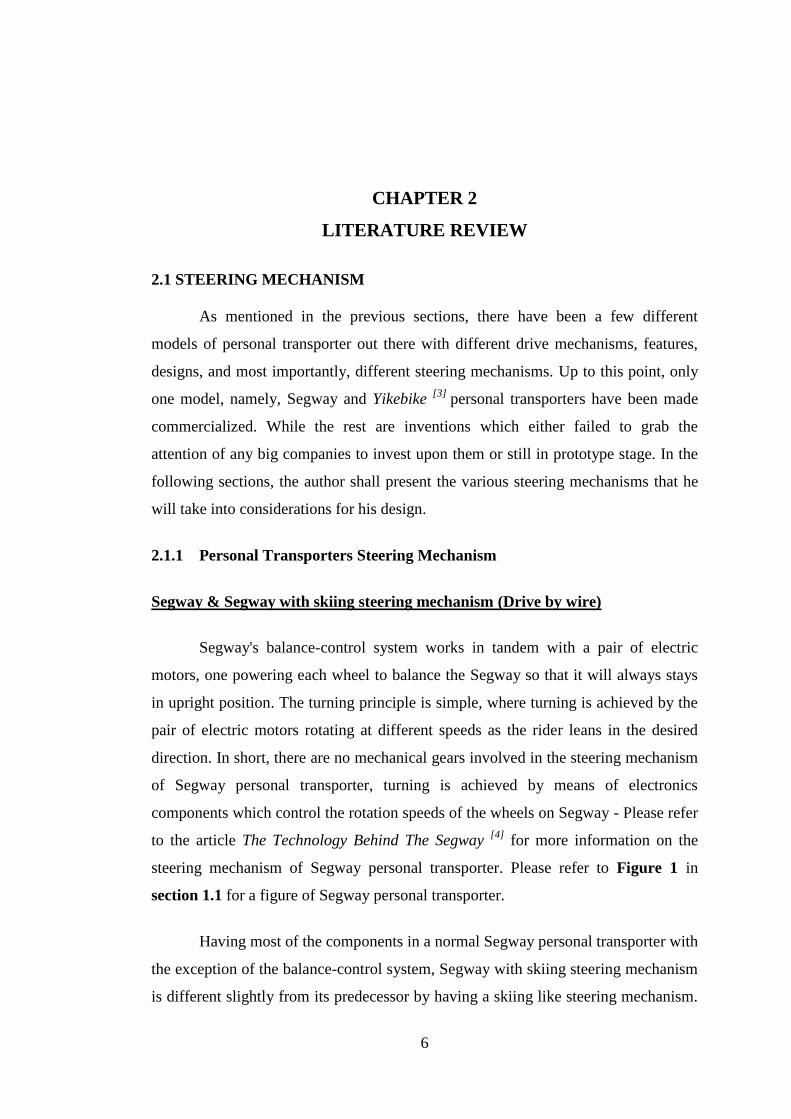
for more information. Figure 4 below
shows a picture of Segway personal transporter with skiing steering mechanism.
Figure 4: Segway Personal Transporter with Skiing Steering Mechanism
2.1.2 Car steering mechanism
Car steering mechanism is a good mechanism to be taken into consideration
for the design of this project‟s steering mechanism in the sense that it is very
established and there are a few design options to be based on. The following sections
show the possible steering box designs of car steering mechanism that could be based
on in designing the steering mechanism for the new personal transporter to be
designed.
Rack and pinion
Rack and pinion is the system predominantly used in road vehicles today. A
pinion is connected by the steering column to the steering wheel. When the steering

8
wheel is rotated, it turns the pinion which is meshed with the mating rack teeth.
Figure 5 in the next page shows a picture of the Rack and Pinion steering box.
Figure 5: Rack and Pinion Steering Mechanism
The pinion rotation is converted to linear movement by the rack which is
supported at one end by a plain bush bearing and at the other end by an adjustable
half bearing support yoke opposite the pinion gear. It is adjusted so that it pushes the
rack into mesh with the pinion gear and minimizes backlash between the two gears.
The circular pitch of the pinion must equal the linear pitch of the rack for correct
operation. This linear movement is relayed through the tie-rod to the track rod arms
and stub axles to the road wheels, which then causes the vehicle to turn the corner -
Please refer to the article How Car Steering Works in the Rack and Pinion Steering
Mechanism section [6]
for more information on this steering mechanism. See Figure
6 in the next page for a picture of steering linkages with a rack and pinion steering
mechanism.

9
Figure 6: Steering Linkages with a Rack and Pinion Steering Mechanism
Early pinion gears were simple straight spur gears but these have been
replaced by helical-toothed pinions. This is because straight cut teeth will mesh with
only one pair of teeth in contact at any one time. Uneven movement of the rack
results from this arrangement as the steering load is transferred from one pair of teeth
to the next.
Helical cut teeth eliminate this problem by having more than one tooth in
contact at any one time which leads to the advantage such as (i) ability to take higher
loads, (ii) quieter and (iii) smoother.
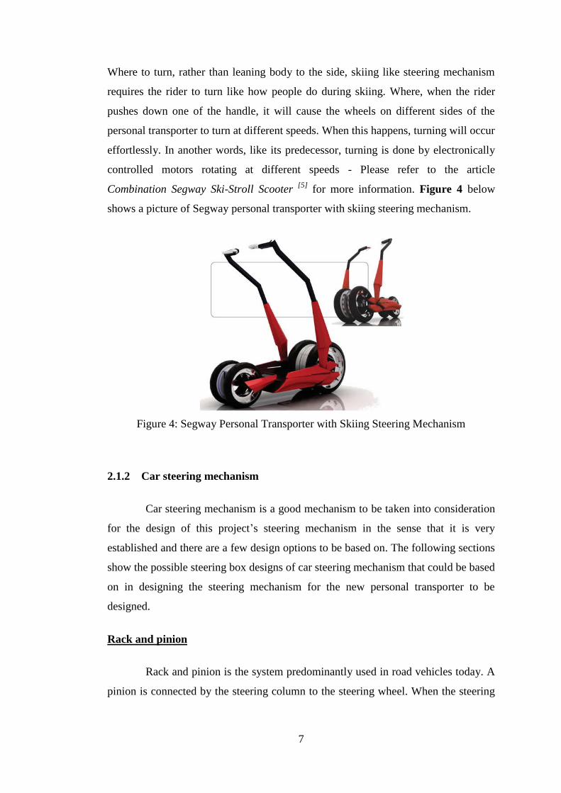
Pinion axis is usually tilted as shown in Figure 7 in the next page from the
perpendicular line to rack as this will increase the effective pitch-radius which allow
fewer and stronger pinion teeth to be used. This will means larger gear-ratio
reductions are possible for a given rack travel. It also increases friction which helps
to reduce the amount of load shock that is transmitted back to the steering wheel and
therefore to the driver.
10
Figure 7: Tilted from Perpendicular Pinion axis to the Rack
The advantages and disadvantages of rack and pinion steering mechanism are as
shown in Table 1: Advantages and Disadvantages of Rack and Pinion Steering Box.
Advantages Disadvantages
- Light compared to other systems
- Cost less than other systems
- Take up a smaller amount of
space than other systems
- Provides good steering response
- Only efficient on small, light
vehicle
Table 1: Advantages and Disadvantages of Rack and Pinion Steering Box
Recirculating ball
Another system that is commonly being employed in car steering system is
the recirculating ball steering. The steering column shaft is connected to a worm gear
inside the steering box. The worm gear acts like a screw and moves the balls back
and forth as the worm gear rotates either one way or the other. The ball nut is held
from rotating so that it moves along the worm gear as it rotates. This movement
rotates a sector gear using teeth on the side of the ball nut, which in turn moves the
pitman arm which causes linear motion on the steering linkages to turn the front
wheels - Please refer to the article Recirculating-ball Steering in How Car Steering
Works [7]
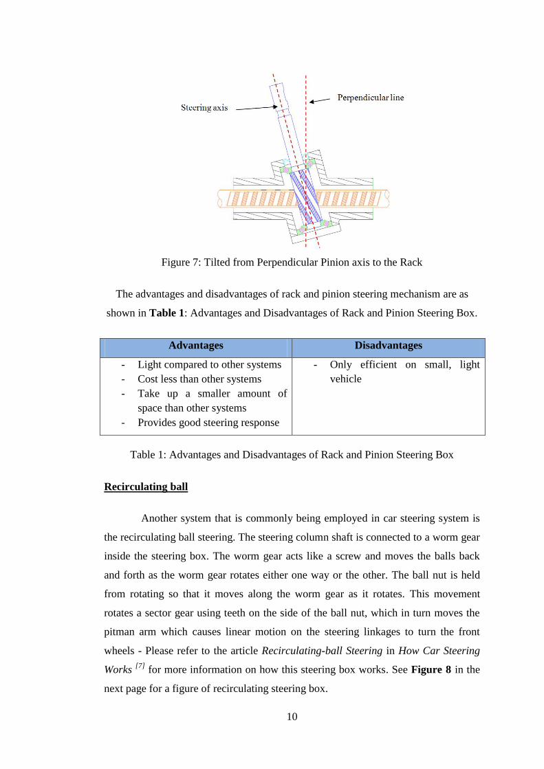
for more information on how this steering box works. See Figure 8 in the
next page for a figure of recirculating steering box.
11
Figure 8: Recirculating Steering Box
Ball bearings and grease are placed between the ball nut and worm gear to
reduce the friction. Thrust washers or spaces are used to adjust internal clearances
between all internal parts. Accuracy in setting these clearances is critical otherwise
there is either free-play in the steering if set too loose, or the systems will bind and
have excessive wear if set too tight.
The advantages and disadvantages of recirculating ball steering box are as
shown in Table 2: Advantages and Disadvantages of Recirculating Ball Steering Box.
Advantages Disadvantages
- Very compact in design
- Very low friction
- Not well suited to front wheel
drive applications because of its
use of a parallelogram steering
linkage which is extremely hard
to fit in a small space available
Table 2: Advantages and Disadvantages of Recirculating Ball Steering Box
Worm and sector
The pitman arm shaft carries a sector gear that meshes with a worm gear
connected to the steering shaft. Because it only turns through an arc of about seventy
degrees, only a sector of gear is needed. When the steering wheel is turned it turns
the worm which rotates the sector. This in turn is connected to the pitman arm on a
shaft. An adjusting nut is provided to adjust end play on the worm which rotates on

12
tapered roller bearings. See Figure 9 below for a figure of worm and sector steering
box.
Figure 9: Worm and Sector Steering Box
Worm and roller
This system is more or less the same as the worm and sector except there is a
roller in place of the sector. The roller rotates on bearings which reduces friction.
When the steering wheel is moved it turns the worm which rotates the roller which
causes the pitman arm to rotate at the other end of the shaft to the roller. The worm
has an hourglass shape which produces good contact in all positions and also
provides a variable steering ratio. Please refer to Figure 10 in Appendix 10 for a
figure of worm and roller steering box.
Figure 10: Worm and Roller Steering Box
13
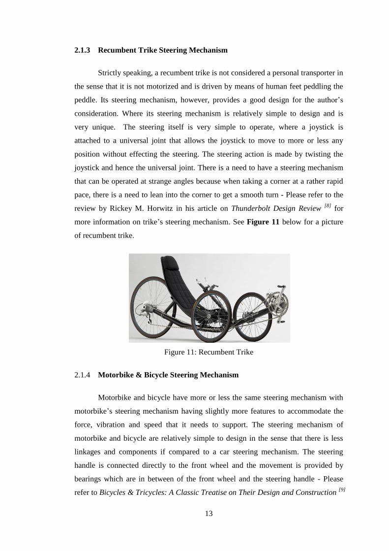
2.1.3 Recumbent Trike Steering Mechanism
Strictly speaking, a recumbent trike is not considered a personal transporter in
the sense that it is not motorized and is driven by means of human feet peddling the
peddle. Its steering mechanism, however, provides a good design for the author‟s
consideration. Where its steering mechanism is relatively simple to design and is
very unique. The steering itself is very simple to operate, where a joystick is
attached to a universal joint that allows the joystick to move to more or less any
position without effecting the steering. The steering action is made by twisting the
joystick and hence the universal joint. There is a need to have a steering mechanism
that can be operated at strange angles because when taking a corner at a rather rapid
pace, there is a need to lean into the corner to get a smooth turn - Please refer to the
review by Rickey M. Horwitz in his article on Thunderbolt Design Review [8]
for
more information on trike‟s steering mechanism. See Figure 11 below for a picture
of recumbent trike.
Figure 11: Recumbent Trike
2.1.4 Motorbike & Bicycle Steering Mechanism
Motorbike and bicycle have more or less the same steering mechanism with
motorbike‟s steering mechanism having slightly more features to accommodate the
force, vibration and speed that it needs to support. The steering mechanism of
motorbike and bicycle are relatively simple to design in the sense that there is less
linkages and components if compared to a car steering mechanism. The steering
handle is connected directly to the front wheel and the movement is provided by
bearings which are in between of the front wheel and the steering handle - Please
refer to Bicycles & Tricycles: A Classic Treatise on Their Design and Construction [9]

14
by Achibald Sharp and Motorcycle Handling and Chassis Design [10]
by Tony Foale
for more information on the steering mechanism for bicycles and motorcycles
respectively.
Despite the availability of many different designs of steering mechanism,
focus will be given to steering mechanism that is effective and simple to be design in
order to ensure that the author‟s goal of designing a steering mechanism that
provides effective turning and low in maintenance cost is achievable.
2.2 MAJOR DESIGN PARAMETERS OF STEERING MECHANISMS
There are a few basic theories that one needs to know before starting to
design any steering mechanism. The basic theories mentioned are as follow:
2.2.1 Two Wheels-based Steering Mechanism
Toe-in and Toe-out
Toe is the symmetric angle that each wheel makes with the longitudinal axis
of the vehicle, as a function of static geometry, kinematic and compliant effects.
Positive toe or toe in is the front of the wheel pointing in towards the centerline of
the vehicle; while negative toe or toe out is the front of the wheel pointing waway
from the centerline of the vehicle. Toe angle is important to ensure that the front
wheels are parallel as a vehicle is moving forward. This is to ensure that there will be
no excessive wear and thus a longer life of front wheels. See Figure 12 in the next
page for a picture of toe in and toe out.
Figure 12: Toe In & Toe Out

15
Camber Angle
This is the angle as viewed from the front of the car, between the plane of the
front wheels and a vertical plane, and is called positive when the top of the wheels
leans outward from the body of the car. A slight positive camber reduces the
cornering power at the front and normally results in an understeering car. Besides,
camber angle is also important for weight adjustment to avoid tire wear. See Figure
13 below for a picture on how camber angle is measured.
Figure 13: Camber Angle, Caster Angle & Kingpin
Caster Angle
It is the angle between the pivot line (in a car – an imaginary line that runs
through the center of the upper ball joint to the center of the lower ball joint) and the
vertical line. Caster angle introduces a self-centering torque when the car is traveling
forward if it is designed properly - which is achieved by the positive offset as shown
in Figure 13 in the previous page where the contact of the tire on the road trails
behind the king pin axis.
King Pin Inclination
It is the traverse angle of the swivel axis of the front wheel and its stub axle.
The effect of the inclination is usually discussed in terms of the king pin offset which
determines the self centering torque when the steering is turned for cornering.

16
Although many cars have a positive value of offset which tends to return the wheel to
the straight ahead position, some modern cars have a negative offset to improve
stability when the tire blows or the brake fails on one front wheel. Please refer to
Figure 13 in the previous page for a picture on how king pin inclination is measured.
Please Refer to Car Suspension and Handling [11]
by Donald Bastow,
Geoffrey Howard and John P. Whitehead for more details on the concepts just
presented by author.
Ackermann steering geometry
Ackermann steering geometry is a geometric arrangement of linkages in the
steering of a car or other vehicle designed to solve the problem of wheels on the
inside and outside of a turn needing to trace out circles of different radii.
A simple approximation to perfect Ackermann steering geometry may be
generated by moving the steering pivot points inward so as to lie on a line drawn
between the steering kingpins and the centre of the rear axle as shown in the Figure
14 in the next page. With perfect Ackermann, at any angle of steering, the centre
point of all of the circles traced by all wheels will lie at a common point. In practice,
however, this may be difficult to achieve with simple linkages arrangement. Please
refer to the article The Ackermann Steering Geometry [12]
for more information on
Ackermann steering geometry.
Modern cars do not use pure Ackermann steering, partly because it ignores
important dynamic and compliant effects, but the principle is sound for low speed
maneuvers. Some race cars use reverse Ackermann geometry to compensate for the
large difference in slip angle between the inner and outer front tires while cornering
at high speed. The use of such geometry helps reduce tire temperatures during high-
speed cornering but compromises performance in low speed maneuvers.

17
Figure 14: Simple approximation to Ackermann Steering Geometry
2.2.2 One Wheel-based Steering Mechanism
Trail
Is the horizontal distance from where the steering axis intersects the ground
to where the front wheel touches the ground. The measurement is considered positive
if the front wheel ground contact point is behind (towards the rear of the bike) the
steering axis intersection with the ground. Large trail values will cause the bike to be
more stable but hard to turn due to large centering force acting on the front wheel.
Thus, care has to be taken when designing a one wheel-based steering mechanism to
ensure that a balance is strike between stability and cornering effort to ensure a good
steering handles. Please refer to Figure 15 in the next page for a clearer picture on
how trail is measured.

18
Figure 15: Trail, Head Angle, Rake and Wheelbase
Steering Axis Angle
The steering axis angle, also called caster angle, is the angle that the steering
axis makes with the horizontal or vertical, depending on convention. The steering
axis is the axis about which the steering mechanism (fork, handlebars, front wheel,
etc.) pivots. The steering axis angle usually matches the angle of the head tube.
In bicycles, the steering axis angle is called the head angle and is measured
clock-wise from the horizontal when viewed from the right side. A 90° head angle
would be vertical. Please refer to Figure 15 as shown above for a clearer picture on
how head angle is measured.
In motorcycles, the steering axis angle is called the rake and is measured
counter-clock-wise from the vertical when viewed from the right side. A 0° rake
would be vertical. Please refer to Figure 16 in the next page for a clearer picture on
how rake angle is measured.

19
Figure 16: Rake Angle on Motorcycle
Wheelbase
Wheelbase is the horizontal distance between the centers (or the ground
contact points) of the front and rear wheels. Wheelbase is a function of rear frame
length, steering axis angle, and fork offset. It is similar to the term wheelbase used
for automobiles and trains. Wheelbase has a major influence on the longitudinal
stability of a bike, along with the height of the center of mass of the combined bike
and rider. Short bikes are much more likely to perform wheelies and stoppies. Please
refer to Figure 15 in the previous page on how wheelbase is measured.
Fork Offset
Fork offset is the perpendicular distance from the steering axis to the center
of the front wheel. Its purpose is for shock absorption.
In bicycles, fork offset is also called fork rake. Virtually all road
racing bicycle forks have almost-standard frame geometry and wheels, so racing
forks are widely interchangeable. Today, some fork blades are straight, having their
offset introduced by an angled fork crown. Before most roads were paved, fork rake
had a lower angle so the fork would be loaded axially on rougher surfaces. As most
roads became paved, bicycles forks were made steeper, which also gave lighter
steering. Please refer to Figure 15 in the page 18 on how rake is measured.
In motorcycles with telescopic fork tubes, fork offset can be implemented by
either an offset in the triple tree, adding a rake angle (usually measured in degrees
from 0) to the fork tubes as they mount into the triple tree, or a combination of the

20
two. Other, less-common motorcycle forks, such as trailing link or leading link forks,
can implement offset by the length of link arms. Please refer to Figure 17 in below
on how Offset is measured on motorcycle.
Please refer to Bicycles & Tricycles: A Classic Treatise on Their Design and
Construction [9]
by Achibald Sharp and Motorcycle Handling and Chassis Design [10]
by Tony Foale for more information on the concepts just presented
Figure 17: Offset on the Triple Clamps

21
CHAPTER 3
METHODOLOGY
To achieve the objectives of this project, the author has developed a flowchart
as shown in Flowchart 1 below to serve as a guideline in order for him to get the
project done within the given time frame.
Flowchart 1: Activities to be carried out in order to
achieve the objectives of this project
There are several activities to be carried out in each step in Flowchart 1; the
activities to be carried out are as the following:
Research (Review existing designs/products)
- Gather information on the various types of steering mechanisms that could be
employed on personal transporter after being re-designed.
ANALYSIS (ESTABLISH STEERING MECHANISM REQUIREMENTS OF
THE NEW DESIGN)
RESEARCH (REVIEW EXISTING DESIGNS/ PRODUCTS)
ANALYSIS (ANALYSE THE STEERING MECHANISM OF
COMMERCIALLY ABAILABLE PERSONAL TRANSPORTER - SEGWAY)
COMPILATION (PREPARE A REPORT)
TECHNICAL DRAWING & ANALYSIS (DEVELOP DETAIL DESIGN)
ANALYSIS (IDENTIFY STEERING MECHANISM TO BE BASED ON FOR
THE AUTHOR’S NEW DESIGN)

22
- Read journals to find out if there is any new yet simple steering technology
that could be incorporated into the author‟s project.
- Gather information of the steering mechanism of commercially available
personal transporter – Segway personal transporter.
Analysis (Analyze the steering mechanism of commercially available personal
transporter - Segway)
- Study the advantages and disadvantages of the steering mechanism of
commercially available personal transporter - Segway.
- Identify the reasons on why commercially available personal transporter like
Segway is not popular in developing countries.
- Study the advantages and disadvantages of each type of steering mechanism
identified in the previous stage.
Analysis (Establish steering mechanism requirements of the new design)
- Set the requirements that need to be achieved by the new design.
- Factors such as size, effectiveness, simplicity, maintainability and cost shall
be considered in this stage.
Analysis (Identify steering mechanism to be based on for the author’s new
design)
- Indentify the best steering mechanism that the new design could be based on.
- Emphasize will be given to steering mechanism that is easy to maintain, low
in cost, simple and effective.
Technical drawing & analysis (Develop detail design)
- Identify the best steering geometry by means of calculations.
- CAD drawing of the conceptual design of the new steering mechanism.
- Force analysis on the new design of steering mechanism for safety purposes.
Compilation (Prepare a report)
- Compilation of findings, designs and results into a report for future reference.
On top of the flowchart prepared earlier, Gantt charts are also developed to
ensure that all the tasks are performed and finished within the timeline give.
Timeline might be altered from time to time to accommodate additional work scope
if deemed necessary. Please refer to Table 3 below and Table 4 in the next page for
the Gantt charts developed by the author.

23
Table 3: Gantt chart (4th
year, 1st semester)
Table 4: Gantt chart (4th
year, 2nd
semester)
No. Detail/ Week 1 2 3 4 5 6 7 8 9 10 11 12 13 14
1 Feasibility study on the project
2 Preliminary research work on different kinds of steering mechanisms
3 Compilation of findings into progress report
4 Continue research on different kinds of steering systems
5 Study on the advantages & disadvantages of each steering mechanism
6 Study in detail on the Segway‟s steering mechanism
7 Study in detail on the various types of alternative steering mechanism
8 Compilation of findings into progress report
9 Preparation of slides for Seminar
10 CAD drawing on steering mechanism (most suitable one)
11 Compilation of findings into Interim report
12 Preparation of slides for oral presentation
No. Detail/ Week 1 2 3 4 5 6 7 8 9 10 11 12 13 14
1 Calculations to get the most suitable dimension of steering linkages
2 Calculations on the forces applied on the steering mechanism
3 Compilation of findings into progress report 1
4 Detailed drawing of design in Auto CAD
5 Compilation of findings into progress report 2
6 Preparation of slides for Seminar
7 Stress analysis on Ansys
8 Simulation of the steering mechanism in Adams
9 Preparation of slides for oral presentation
10 Compilation of findings and results into Dissertation report
Mid
-sem
este
r bre
ak
Mid
-sem
este
r bre
ak

24
CHAPTER 4
RESULTS AND DISCUSSION
After reviewing the steering mechanisms that could be employed on personal
transporter, the author shall then identify the best steering mechanism to base his
design on. Design criteria and specifications have to be established before decision
could be made and they are as the following:
Design criteria that should be met by the steering design are as shown in Table 5:
Design Criteria.
Criteria Description
Low Cost Contributes to the overall low cost of the final design.
Simple Design Technologies available in developing countries.
Easy to Maintain Replacement components available in developing countries.
High Effectiveness Provides good turning and stability to the personal
transporter.
Small in Size Take up little space to ensure compact overall design.
Table 5: Design Criteria
While the design specifications that should be met by the design are as the following:
i) Provides stable cornering capability to personal transporter traveling at a speed
range of 0.0 km/h -20.0 km/h.
ii) Its structure should be able to support up to 120.0 kg of weight.
iii) Provides ground clearance of at least 7.5 cm
iv) Footprint of 48.0 cm x 60.0 cm
v) Turning radius of less than 4.5 m
The designs specifications above are set above are based on commercially
available personal transporter – Segway personal transporter. Design specifications
are subjected to change from time to time depending on requirements and new design

25
specifications will be added should the needs arise. Having set the design criteria and
specifications, author has come out with three conceptual designs as shown in the
following pages.

26
4.1 CONCETUAL DESIGNS
Conceptual Design 1
Figure 18: Conceptual Design 1
Steering Wheel
Rack and Pinion
Steering Mechanism
Two-Wheels based
Steering Mechanism.
Platform
27
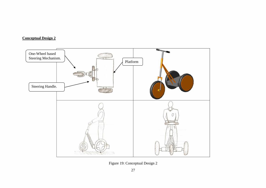
Conceptual Design 2
Figure 19: Conceptual Design 2
One-Wheel based
Steering Mechanism.
Steering Handle.
Platform

28
Conceptual Design 3
Figure 20: Conceptual Design 3
Steering Handle.
Four bar linkages
to provide tilting to
the steering.
One-Wheel based
steering mechanism.
Platform

29
4.2 CONCETUAL DESIGN DETAIL DESCRIPTIONS
Conceptual Design 1
This conceptual design has only two wheels which mean maneuvering and
power drive are carried out by the same two wheels. There will be a need for self-
balancing system in order for this conceptual design to work. The steering
mechanism being employed on this conceptual design is the rack and pinion steering
mechanism. The maneuvering for this is done by the rider turning the steering wheel
which in turn rotates the steering shaft which is connected a universal joint which
ultimately turns the pinion that is connected to the rack of steering mechanism.
Flowchart 2 below summarizes how turning is done on conceptual design 1:
Flowchart 2: Working Principle of Conceptual Design 1‟s Steering Mechanism
Figure 21 below shows the steering mechanism of this conceptual design:
Figure 21: Steering Mechanism for Conceptual Design 1
Rider turns the
steering wheel
Steering shaft is
turned
Pinion which is connected to the steering
shaft via a universal joint is turned
Rack is moved by the turning pinion and
maneuvering is achieved by the turning wheels
which are connected to the rack.
Steering Wheel
Rack and Pinion
Steering Box
Steering Shaft
Universal Joint

30
Conceptual Design 2
This conceptual design has three wheels as shown previously in page 26 -
Figure 19, where two wheels are installed at the platform and one at the front.
Maneuvering is done by the front wheel via motorbike/ bicycle based steering
mechanism. Simple enough, the maneuvering is done simply by turning the steering
handle which is connected directly to the front wheel. This steering mechanism gives
turning ratio of 1:1. Figure 22 below shows the steering mechanism of this
conceptual design:
Figure 22: Steering Mechanism for Conceptual Design 2
Conceptual Design 3
Like conceptual design 2, this conceptual design also has three wheels.
Namely, two wheels at the platform and one at the front as shown in page 27 –
Figure 20. Besides, this conceptual design also has a steering mechanism which is
based on motorcycle/ bicycle. What set it apart from conceptual design 2 is the fact
that it is equipped with a four bar linkages system which make it possible for the
steering mechanism to tilt during turning. The tilting effect that is achieved by the
four-bar linkages during turning will definitely increase the stability during turning
by a great margin - Please refer to the technical report titled Development of a Novel
Three-Wheeled Vehicle [13]
by V. Cossalter, N. Ruffo, F. Biral, R. Berritta from
Department of Mechanical Engineering, University of Padua for more information
on the four bar linkages system presented. Figure 23 in the next page shows the
steering mechanism for this conceptual design.
Steering Handle
Fixed to
Platform
Bearings

31
Figure 23: Steering Mechanism for Conceptual Design 3
While Figure 24 below shows the four bar linkages positions during 29 degrees
tilting of the steering mechanism on both sides:
Figure 24: Four Bar Linkages Position during 29 degrees Tilting on Both
Sides
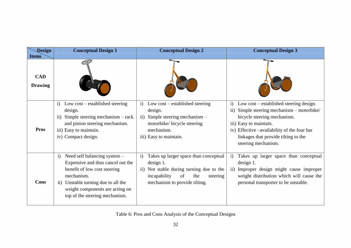
Having discussed the steering mechanism for each conceptual design, the
pros and cons of each design are analyzed and presented in Table 6 in the next page:
Steering Handle
Four-bar linkages system -
enable the tilting of the
steering mechanism.
Bearings
32
Design
Items
Conceptual Design 1 Conceptual Design 2 Conceptual Design 3
CAD
Drawing
Pros
i) Low cost – established steering
design.
ii) Simple steering mechanism – rack
and pinion steering mechanism.
iii) Easy to maintain.
iv) Compact design.
i) Low cost – established steering
design.
ii) Simple steering mechanism –
motorbike/ bicycle steering
mechanism.
iii) Easy to maintain.
i) Low cost – established steering design.
ii) Simple steering mechanism – motorbike/
bicycle steering mechanism.
iii) Easy to maintain.
iv) Effective –availability of the four bar
linkages that provide tilting to the
steering mechanism.
Cons
i) Need self balancing system –
Expensive and thus cancel out the
benefit of low cost steering
mechanism.
ii) Unstable turning due to all the
weight components are acting on
top of the steering mechanism.
i) Takes up larger space than conceptual
design 1.
ii) Not stable during turning due to the
incapability of the steering
mechanism to provide tilting.
i) Takes up larger space than conceptual
design 1.
ii) Improper design might cause improper
weight distribution which will cause the
personal transporter to be unstable.
Table 6: Pros and Cons Analysis of the Conceptual Designs

33
From the pros and cons analysis of the three conceptual designs, it is obvious
that conceptual design 1 has the advantage of being a compact design. Yet, the facts
that conceptual design 1 only has two wheels and that all the weight components are
acting on its steering mechanism have caused it to be extremely unstable during
cornering. Not to mention the requirement of a self-balancing system which is
expensive that will cancel out the compact benefit of conceptual design 1.
While for conceptual design 2, it has the advantage of being more stable than
conceptual design 1 due to the addition of a third wheel in front of the platform. On
top of that, it has a lower overall cost of production than conceptual design 1 since it
does not require self-balancing system. This design, however, is still not good
enough in the sense that the steering mechanism could not tilt during cornering
which make it still not very stable during cornering.
For conceptual design 3, it has all the advantages of conceptual design 2.
What makes it stands out from the rest is its four-bar linkages system which allows
its steering mechanism to tilt during cornering for stability. This has made it the most
feasible design that meet the author„s needs of designing a steering mechanism for
personal transporter that is low in cost and provides effective turning.
4.3 DECISION MATRIX
In the previous section, it is obvious that conceptual design 3 is the best
design function wise – without taking into consideration of currently existing
personal transporters in the market such as Segway personal transporter and Yike
bike. Yet, more considerations and studies have to be done before final decision
could be made on which design is the best as there are few factors that the author
needs to look into such as cost, simplicity of design, maintainability and
effectiveness.
To ensure that the final design chosen meets all the design criteria set earlier,
the author decided to employ decision matrix to compare between the conceptual
designs and currently available personal transporter on the market like Segway and
Yikebike personal transporters. Besides, the author also employed decision matrix to

34
compare between one-wheel based steering mechanism and two-wheel based
steering mechanism.
It should be bear in mind that the project‟s main focus is to develop a steering
mechanism that is low in cost yet effective so that the overall cost of a new personal
transporter to be developed is low and thus affordable to citizens living in cities in
developing countries.
Table 7 in the next page shows the decision matrix to choose the steering
mechanism that best suits all the design criteria set earlier. While Table 6 in page 35
shows the decision matrix to choose between one-wheel based steering mechanism
and two-wheel based steering mechanism.

35
Decision Making Criteria
Op
tio
ns
Criteria
Options
Cost Design
Complexity
Maintainability Effectiveness Size Total
Segway 5 2 4 9 9 29
Yikebike 5 3 4 9 9 30
Conceptual Design 1 7 7 8 2 7 31
Conceptual Design 2 9 9 9 3 4 34
Conceptual Design 3 8 8 9 7 4 36
Table 7: Decision matrix to choose the best steering mechanism
Note: The rating is in the range of 1 – 10, where 10 represent the best and 1 represents the worst.
Ex: Complexity of design
10 = Very simple design
1 = Very complex design
From the decision matrix analysis, it becomes immediately apparent that conceptual design 3 is the best in terms of serving the objectives
set earlier in this project, which is to develop a low cost personal transporter that is affordable to people living in developing countries which
ultimately leads to the easing of pollutions and congestion problems in cities. Despite this design has the disadvantage of being relatively larger
in size, it serves the other design criteria of this project nicely. This is mainly due to its four-bar linkages system that gives it the advantage of
being more stable than conceptual designs 2 and 1 during cornering.

36
While the second design that best suits the design criteria of this project is
conceptual design 2. Despite its relatively low stability during cornering (low
effectiveness), it achieves the other design criteria of this project nicely - low cost,
easy to maintain and simple design. Conceptual design 1 comes next after conceptual
design 2 as the steering mechanism that best suits the design criteria set. Again,
despite its low effectiveness, it manages to achieve the other design objectives better
than the Segway and Yikebike personal transporters.
Last but not least, the least favorable options in terms of achieving the design
criteria of this project are the Segway and Yikebike steering mechanisms. Despite
their highly sophisticated technology and designs, they failed to fair in this project
because the project‟s main concerns are low cost, simple design and easy to maintain
which are not the strong points of the two products.
4.4 CALCULATIONS
4.4.1 Calculations for Steering Geometry
With the design criteria, specifications and conceptual design decided upon.
Calculations were performed in order to get the geometry of the new steering
mechanism to be designed.
In the following pages, the author presented on how parameters that are
important for the stability and maneuvering of his steering mechanism design,
namely, (i) fork offset, (ii) trail and (iii) caster angle were determined and decided
upon. Radius of steering wheel to be used in the author‟s design is also fixed later on
as it will affect the values of trail and caster angle.
Fork Offset
As mentioned in the theory part, offset is important for shock absorption.
There is no specific limitation though on what is the range that offset value should be
in. In industrial practice, prototypes at a range of fork offset values are tested in lab
to see the amount of stress that steering at various fork offset could withstand before
it fails. The best offset value is then selected to be used in the final design of their
product. In the author‟s case, however, an offset value will be selected from a range
that is generally employed on motorcycles and bicycles (0.036m – 0.05m) due to the

37
unavailability of budget to produce prototypes at various fork offset values for
testing purposes.
The fork offset value to be employed in the author‟s design is not very critical
in the sense that personal transporter is designed to be used in cities where the roads
are properly paved and there will not be much vibration experienced by the wheels.
Thus, the author decided to fix the fork offset value of the steering mechanism to be
designed to 0.0036m.
Trail and Caster Angle
Trail and caster angle are closely related to each other, where an increase in
trail will be accompanied by an increase in caster angle for stability. In fact, trail and
caster angle are related to each other through the following formula:
a = Rf × tanε −d
cosε
Where:
a is the trail
Rf is the radius of the front wheel
d is the fork offset
ε is the caster angle
There is large combination of trail and caster values that the author can use as
any change in the front wheel radius, Rf and fork offset, d will lead to another set of
trail and rake angle combination. To reduce the variables in designing the steering
mechanism, the author has decided to use a wheel with a radius of 24cm (Please refer
to “fixed design parameters” section in the next page for justification of using 24cm
wheel radius) for his design. Besides, to get some guidelines in designing his steering
mechanism, the author has done researches on the trail and caster angle combination
of motorcycle and bicycle available nowadays. Tables 8 and 9 in the next page show
the general combination of trail and caster angle for motorcycles and bicycles
respectively:
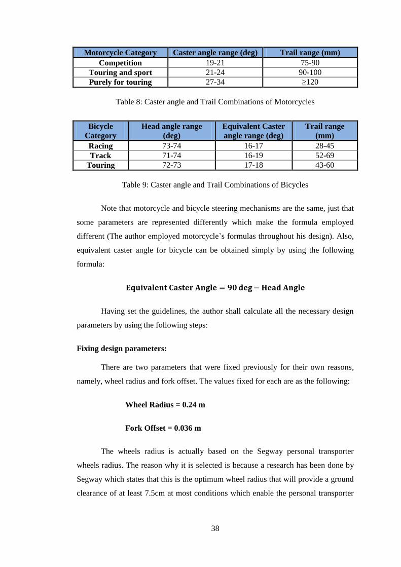
38
Motorcycle Category Caster angle range (deg) Trail range (mm)
Competition 19-21 75-90
Touring and sport 21-24 90-100
Purely for touring 27-34 ≥120
Table 8: Caster angle and Trail Combinations of Motorcycles
Bicycle
Category
Head angle range
(deg)
Equivalent Caster
angle range (deg)
Trail range
(mm)
Racing 73-74 16-17 28-45
Track 71-74 16-19 52-69
Touring 72-73 17-18 43-60
Table 9: Caster angle and Trail Combinations of Bicycles
Note that motorcycle and bicycle steering mechanisms are the same, just that
some parameters are represented differently which make the formula employed
different (The author employed motorcycle‟s formulas throughout his design). Also,
equivalent caster angle for bicycle can be obtained simply by using the following
formula:
𝐄𝐪𝐮𝐢𝐯𝐚𝐥𝐞𝐧𝐭 𝐂𝐚𝐬𝐭𝐞𝐫 𝐀𝐧𝐠𝐥𝐞 = 𝟗𝟎𝐝𝐞𝐠− 𝐇𝐞𝐚𝐝 𝐀𝐧𝐠𝐥𝐞
Having set the guidelines, the author shall calculate all the necessary design
parameters by using the following steps:
Fixing design parameters:
There are two parameters that were fixed previously for their own reasons,
namely, wheel radius and fork offset. The values fixed for each are as the following:
Wheel Radius = 0.24 m
Fork Offset = 0.036 m
The wheels radius is actually based on the Segway personal transporter
wheels radius. The reason why it is selected is because a research has been done by
Segway which states that this is the optimum wheel radius that will provide a ground
clearance of at least 7.5cm at most conditions which enable the personal transporter
39
to travel though water puddle that you might come across in cities roads safely
without spoiling the electrical components in the personal transporter.
While the fork offset value is selected for the reason mentioned in the “fork
offset” part in page 37 of this report.
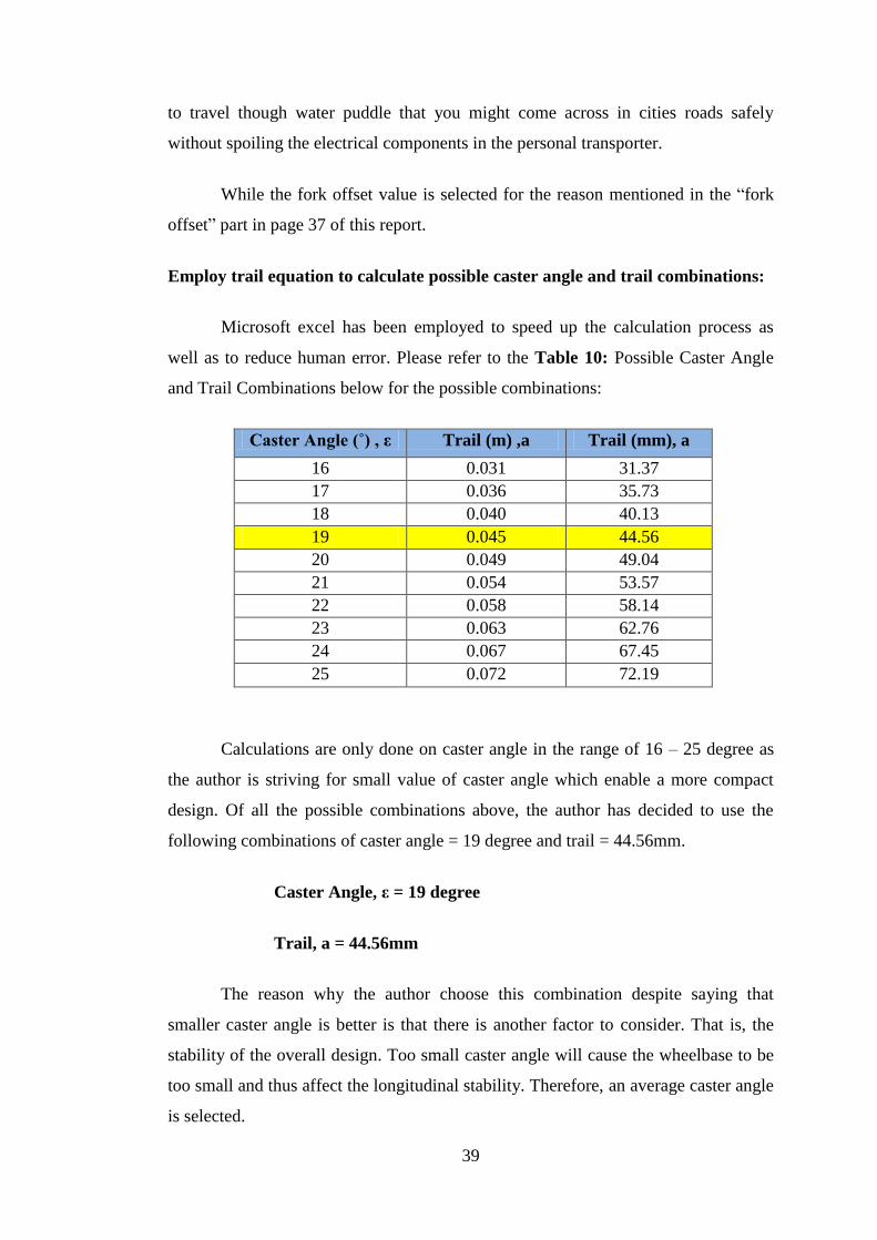
Employ trail equation to calculate possible caster angle and trail combinations:
Microsoft excel has been employed to speed up the calculation process as
well as to reduce human error. Please refer to the Table 10: Possible Caster Angle
and Trail Combinations below for the possible combinations:
Caster Angle (˚) , ε Trail (m) ,a Trail (mm), a
16 0.031 31.37
17 0.036 35.73
18 0.040 40.13
19 0.045 44.56
20 0.049 49.04
21 0.054 53.57
22 0.058 58.14
23 0.063 62.76
24 0.067 67.45
25 0.072 72.19
Calculations are only done on caster angle in the range of 16 – 25 degree as
the author is striving for small value of caster angle which enable a more compact
design. Of all the possible combinations above, the author has decided to use the
following combinations of caster angle = 19 degree and trail = 44.56mm.
Caster Angle, ε = 19 degree
Trail, a = 44.56mm
The reason why the author choose this combination despite saying that
smaller caster angle is better is that there is another factor to consider. That is, the
stability of the overall design. Too small caster angle will cause the wheelbase to be
too small and thus affect the longitudinal stability. Therefore, an average caster angle
is selected.
40
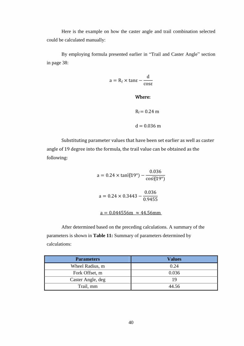
Here is the example on how the caster angle and trail combination selected
could be calculated manually:
By employing formula presented earlier in “Trail and Caster Angle” section
in page 38:
a = Rf × tanε −d
cosε
Where:
Rf = 0.24 m
d = 0.036 m
Substituting parameter values that have been set earlier as well as caster
angle of 19 degree into the formula, the trail value can be obtained as the
following:
a = 0.24 × tan(19°) −0.036
cos(19°)
a = 0.24 × 0.3443 −0.036
0.9455
a = 0.044556m ≈ 44.56mm
After determined based on the preceding calculations. A summary of the
parameters is shown in Table 11: Summary of parameters determined by
calculations:
Parameters Values
Wheel Radius, m 0.24
Fork Offset, m 0.036
Caster Angle, deg 19
Trail, mm 44.56

41
The rest of the parameters are automatically known with the determination of
the parameters of the steering mechanism and design specifications set earlier. The
perpendicular distance between the steering handle and the center of the platform
where the rider stands is set to be 40cm for the comfort gesture of the rider. Please
refer to Bicycles & Tricycles: A Classic Treatise on Their Design and Construction [9]
by Achibald Sharp and Motorcycle Handling and Chassis Design [10]
by Tony Foale
for more information on the generally employed values, formulas and design
considerations presented in this section. Please refer to the sketch below for the
overall parameters of the whole personal transporter:
Figure 25: Sketch with important overall parameters
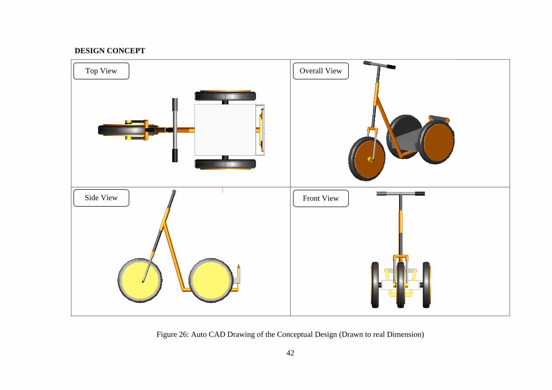
Having determined all the important parameters for the steering mechanism,
as well as the parameters decided earlier such as footprint of 48.0 cm X 60.0 cm for
the platform on which the rider stands, the author had drawn an AutoCAD drawing
of his design to scale as shown in the next page.
42
DESIGN CONCEPT
Figure 26: Auto CAD Drawing of the Conceptual Design (Drawn to real Dimension)
Overall View Top View
Side View Front View

43
4.4.2 Calculations for Stability Analysis
Having decided upon the parameters of the steering mechanism as well as the
dimensions of the overall personal transporter, it is time to analyze the stability of the
overall design. The design‟s primary stability concern will be its turning stability. To
analyze the turning stability, the following assumptions and calculations are
performed:
To simplify the analysis, the author has made the following assumptions:
- The steering wheel is the driving wheel.
- The rear wheels are mounted independently on the axle. (So that they will
rotate at their respective proper speeds during turning automatically.)
- Rider‟s weight = 80 kg. (The weight could be any reasonable value as it
will not affect the final results.)
- Personal transporter‟s overall weight is 50 kg
- Right cornering at a turning radius of 2 m from the rider‟s point of view.
- Cornering is done at 50% of the maximum velocity, namely10 km/h.
The free body diagram of the personal transporter designed is shown in Figure 27:
Figure 27: Free Body Diagram
44
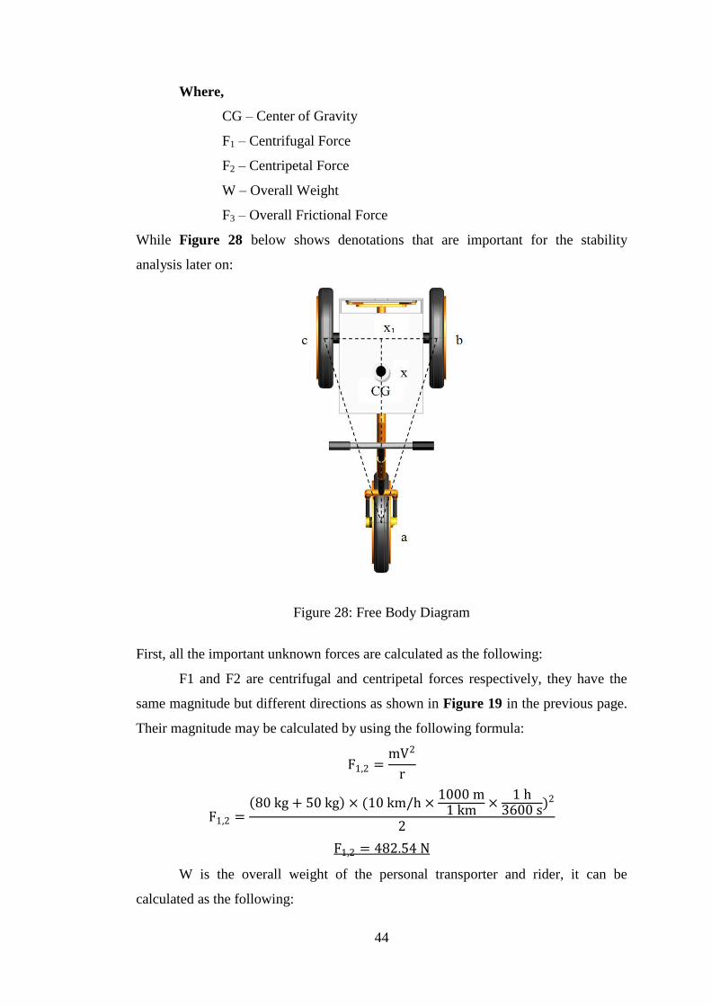
Where,
CG – Center of Gravity
F1 – Centrifugal Force
F2 – Centripetal Force
W – Overall Weight
F3 – Overall Frictional Force
While Figure 28 below shows denotations that are important for the stability
analysis later on:
Figure 28: Free Body Diagram
First, all the important unknown forces are calculated as the following:
F1 and F2 are centrifugal and centripetal forces respectively, they have the
same magnitude but different directions as shown in Figure 19 in the previous page.
Their magnitude may be calculated by using the following formula:
F1,2 =mV2
r
F1,2 = 80 kg + 50 kg × (10 km/h ×
1000 m1 km
×1 h
3600 s)2
2
F1,2 = 482.54 N
W is the overall weight of the personal transporter and rider, it can be
calculated as the following:

45
W = (Rider′sMass + Personal Transporter′sMass) × gravitational Acceleration
W = 80 kg + 50 kg × 9.81 ms2
W = 1275.30 N
Now, F3 shall be calculated as the following:
- Since F3 is the overall frictional forces due the contact points of the three
wheels at a, b and c. The author‟s shall first find the weight at each of the
wheel by using principle of moments as the following:
To find weight on wheel a, the author uses the equation of equilibrium of
moments around axes b and c as the following:
W × xx1 = wa × ax1
50 kg + 80 kg × 9.81 ms2 × 36 cm ×
10−2 m
1 cm= wa × 88 cm ×
10−2 m
1 cm
wa = 521.71 N
While to find weight on wheels b and c, the author uses the equation of
equilibrium of moments around axes a as the following:
W × xa = wb&𝑐 × ax1
50 kg + 80 kg × 9.81 ms2 × 52 cm ×
10−2 m
1 cm= wb&𝑐 × 88 cm ×
10−2 m
1 cm
wb&𝑐 = 753.59 N
wb = wc =753.59 N
2= 376.79 N
- F3 is simply the summation of the frictional forces at each of the wheels
as the following:
F3 = μwa + μwb + μwc
Where
μ is the coefficient of friction and is assumed to
be 1.7 for tire and concrete contact under good
condition
F3 = 1.7 × 521.71 N + 1.7 × 376.79 N + 1.7 × 376.79 N
F3 = 2167.99 N
Having obtained all the important forces, the author tested the turning stability of his
design by using the principle presented in chapter XVII – Stability of Cycles in the

46
book titled “Bicycles &Tricycles: A Classic Treatise on Their Design and
Construction [9]
by Archibald Sharp” which states that if the resultant force, R of W
and F1 cut the ground at point p, (as shown in Figure 29 below) outside the
wheelbase a, b and c. Then the design will overturn.
Figure 29: Free Body Diagram
Thus, to check for the turning stability of the author‟s design. Force analysis
is carried out based on the values calculated earlier as shown in the Figure 30 in the
next page.
From the force analysis carried out (Please refer to Figure 30 in the next
page), we can see that the resultant force is still within the wheelbase a,b and c of the
vehicle. Even though the point p crosses the wheelbase at margin, it is good enough
to show that the design is still stable in terms of turning stability if a rider is to turn
through a turning radius of 2m at a speed of 10km/h. Besides, it should be bear in
mind that the analysis above is carried out without considering the tilting capability
of the steering mechanism yet. Thus, the author can conclude that the design is safe
to turn through a turning radius of 2 m at a speed of 10km/h.
p

47
Figure 30: Force Analysis
48
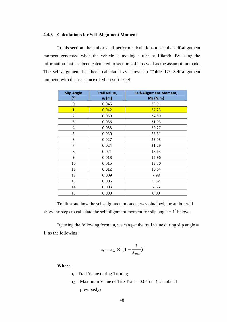
4.4.3 Calculations for Self-Alignment Moment
In this section, the author shall perform calculations to see the self-alignment
moment generated when the vehicle is making a turn at 10km/h. By using the
information that has been calculated in section 4.4.2 as well as the assumption made.
The self-alignment has been calculated as shown in Table 12: Self-alignment
moment, with the assistance of Microsoft excel:
Slip Angle (o)
Trail Value, at (m)
Self-Alignment Moment, Mz (N.m)
0 0.045 39.91
1 0.042 37.25
2 0.039 34.59
3 0.036 31.93
4 0.033 29.27
5 0.030 26.61
6 0.027 23.95
7 0.024 21.29
8 0.021 18.63
9 0.018 15.96
10 0.015 13.30
11 0.012 10.64
12 0.009 7.98
13 0.006 5.32
14 0.003 2.66
15 0.000 0.00
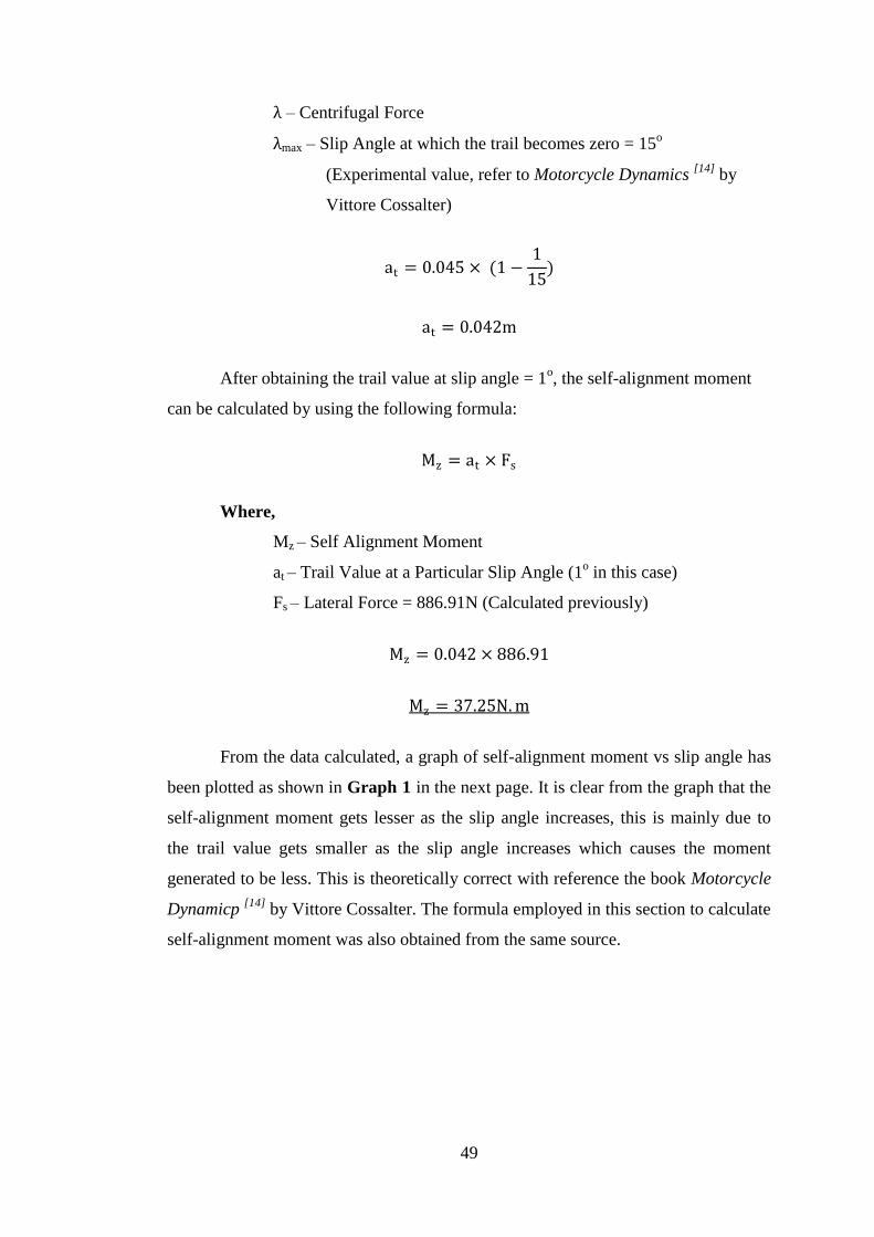
To illustrate how the self-alignment moment was obtained, the author will
show the steps to calculate the self alignment moment for slip angle = 1o below:
By using the following formula, we can get the trail value during slip angle =
1o as the following:
at = at0× (1 −
λ
λmax)
Where,
at – Trail Value during Turning
at0 – Maximum Value of Tire Trail = 0.045 m (Calculated
previously)
49
λ – Centrifugal Force
λmax – Slip Angle at which the trail becomes zero = 15o
(Experimental value, refer to Motorcycle Dynamics [14]
by
Vittore Cossalter)
at = 0.045 × (1 −1
15)
at = 0.042m
After obtaining the trail value at slip angle = 1o, the self-alignment moment
can be calculated by using the following formula:
Mz = at × Fs
Where,
Mz – Self Alignment Moment
at – Trail Value at a Particular Slip Angle (1o in this case)
Fs – Lateral Force = 886.91N (Calculated previously)
Mz = 0.042 × 886.91
Mz = 37.25N. m
From the data calculated, a graph of self-alignment moment vs slip angle has
been plotted as shown in Graph 1 in the next page. It is clear from the graph that the
self-alignment moment gets lesser as the slip angle increases, this is mainly due to
the trail value gets smaller as the slip angle increases which causes the moment
generated to be less. This is theoretically correct with reference the book Motorcycle
Dynamicp [14]
by Vittore Cossalter. The formula employed in this section to calculate
self-alignment moment was also obtained from the same source.

50
Graph 1: Graph of Self Alignment Moment Vs Slip Angle
Also, from the calculated self-alignment data in the previous page, the author
has also calculated the steering force needed to make the turn as shown in Table 13:
Steering force:
Again, for clarity purposes, the author will show the calculations to get the
steering force needed to turn the corner below:
0.00
10.00
20.00
30.00
40.00
50.00
0 2 4 6 8 10 12 14 16
Self
-Alig
nm
en
t M
om
en
t (N
.m)
Slip Angle (O)
Graph of Self-Alignment Moment Vs Slip Angle
Slip Angle, (o) Self-Alignment Moment, Mz (N.m) Steering Force, (N)
0 39.91 79.82
1 37.25 74.50
2 34.59 69.18
3 31.93 63.86
4 29.27 58.54
5 26.61 53.21
6 23.95 47.89
7 21.29 42.57
8 18.63 37.25
9 15.96 31.93
10 13.30 26.61
11 10.64 21.29
12 7.98 15.96
13 5.32 10.64
14 2.66 5.32
15 0.00 0.00

51
Taking slip angle = 1o as an example, the steering force can be calculated by
using the following formula:
FS = Mz
L
Where,
FS – Steering Force
Mz – Self-Alignment Moment
L – Length of Steering Bar = 0.5m
FS = 37.25
0.5
FS = 74.50 N
From the calculated values, one can observe that the steering force to initiate
the turn is large initially and it gets lower as the turning angle gets successively large
due to the reduction in self-alignment moment.

52
CHAPTER 5
CONCLUSIONS & RECOMMENDATIONS
In a nutshell, a conceptual design which employs a four bar linkage to
provide tilting for the steering mechanism is the best design that could serve the
objectives of this project. Namely, to design a steering mechanism for a personal
transporter that is low in cost, easy to maintain, simple design and provides effective
turning to the new personal transporter to be designed sometime in the future. If the
overall project is a success, it will not be long before citizens in developing countries
can afford a cheap personal transporter that could ultimately help to solve the
congestion and pollution problems in cities.
Besides, in order to improve the design. The author would recommend that
the successor of this project to do the following items:
- Conduct simulation in Adams to further ensure its stability at various speeds.
- Conduct simulation in Ansys to check for the robustness of the design.
- Come out with a prototype to test ride.
53
REFERENCES
1) Segway Inc. 2010 <http://www.segway.com/about-segway/segway-
milestones.php>
2) Listessa. 2008 <http://hubpages.com/hub/How-much-dose-a-Segway-
Scooter-cost>
3) YikeBike Inc. 2010 <http://www.yikebike.com/site/home>
4) Mark Hachman. 12th
December 2001
<http://www.extremetech.com/article2/0,2845,26752,00.asp>
5) Sarah Park. 15th
April 2008
<http://www.impactlab.com/2008/04/15/combination-segway-ski-stroll-
scooter/>
6) Karim Nice. <http://auto.howstuffworks.com/steering2.htm>
7) Karim Nice. <http://auto.howstuffworks.com/steering3.htm>
8) Rickey M. Horwitz. 5th
February 2000
<http://www.ihpva.org/Projects/PracticalInnovations/tboltdesign.html>
9) Archibald Sharp. 2003, Bicycles & Tricycles: A Classic Treatise on Their
Design and Construction, New York, Dover Publications, Inc.
10) Tony Foale. 2006, Motorcycle handling and chassis design, the art and
science. Spain.
11) Donald Bastow, Geoffrey Howard, John P. Whitehead. 2004, Car Suspension
and Handling, New York, John Wiley & Sons.
12) Mark Mckeown. 2007.
<http://me-wserver.mecheng.strath.ac.uk/group2006/groupm/steering.htm>
13) V. Cossalter, N. Ruffo, F. Biral, R. Berritta, 2000. Development of a Novel
Three-Wheeled Vehicle. University of Padua, Italy.
14) Vittore Cossalter. 2006, Motorcycle Dynamics, Race Dynamics Inc.