Design of a Screw Plate System to Minimize Screw … of a Screw Plate System to Minimize Screw...
78
KLB-1002 1 Design of a Screw Plate System to Minimize Screw Loosening in Sternal Fixation April 2011 A Major Qualifying Project Report: Submitted to the Faculty of the Worcester Polytechnic Institute In partial fulfillment of the requirements of the Degree of Bachelor of Science by _________________________ David Song __________________________ John Brunelli __________________________ Peter Costello __________________________ Michael Ford 1) Sternum 2) Rigid fixation 3) Bone Screws ______________________ Prof. Kristen Billiar, Major Advisor ______________________ Dr. Raymond Dunn, Co-Advisor
Transcript of Design of a Screw Plate System to Minimize Screw … of a Screw Plate System to Minimize Screw...

KLB-1002
1
Design of a Screw Plate System to Minimize Screw Loosening in Sternal Fixation
April 2011
A Major Qualifying Project Report:
Submitted to the Faculty of the
Worcester Polytechnic Institute
In partial fulfillment of the requirements of the
Degree of Bachelor of Science
by
_________________________
David Song
__________________________
John Brunelli
__________________________
Peter Costello
__________________________
Michael Ford
1) Sternum
2) Rigid fixation
3) Bone Screws
______________________
Prof. Kristen Billiar, Major Advisor
______________________
Dr. Raymond Dunn, Co-Advisor

KLB-1002
2
Acknowledgements
The authors of this design project would like to thank the following individuals for their help:
Professor Kristen Billiar for his guidance and support throughout the project and the use of the core
facility at Gateway.
Raymond Dunn, MD and Ronald Ignotz, MD for their clinical experience, insight and support.
John Dieselman for his mechanical testing experience and use of his anti-wobble screw-plate system.
Authorship All group members participated equally in the writing and editing of this report.

KLB-1002
3
Abstract
The use of screw-plate fixation devices after sternotomy procedures is becoming more prevalent with
studies showing the mechanical superiority of such devices. However, there is no current device that is
capable of supplying both the compressive and locking forces needed to optimally fixate the plate to the
bone. The goal of this project is to create an anti-wobble screw-plate fixation device capable of reducing
sternal displacement after fixation using clinically relevant materials. The design achieves this anti-
wobble effect through the use of a modified one piece, two-part screw that allows for full compression
between the bone-plate interface before locking into the plate. The device was designed and manufactured
to clinical specifications in the final prototype, and the anti-wobble concept was tested in a bone analog
and human cadaveric sternum using an earlier prototype. Using a uniaxial mechanical testing machine,
cyclic loading from 0 to 25N was applied for 15,000 cycles to mimic breathing forces. The anti-wobble
concept, having both compression and locking, reduced displacement of the bone plate on a sternal
segment. In a bone analog, the displacements for standard nonlocking and anti-wobble systems were
0.57mm and 0.20mm, respectively. The experimental results indicate that the anti-wobble system may
significantly minimize screw-displacement, and a clinically relevant product was developed.
KLB-1002
4
Table of Contents
Acknowledgements ....................................................................................................................................... 2
Authorship .................................................................................................................................................... 2
Abstract ......................................................................................................................................................... 3
Table of Contents .......................................................................................................................................... 4
Table of Figures ............................................................................................................................................ 6
1 Introduction ........................................................................................................................................... 9
2.0 Background ........................................................................................................................................... 11
2.1 Clinical Statistics .............................................................................................................................. 11
2.2 Sternum Anatomy and Physiology ................................................................................................... 12
2.3 Sternotomy procedure ....................................................................................................................... 13
2.4 Current Methods ......................................................................................................................... 13
2.4.1 Non-rigid Fixation...................................................................................................................... 13
2.4.2 Rigid fixation ............................................................................................................................. 14
2.4.3 Cerclage Wire ............................................................................................................................ 14
2.4.4 Rapid Sternal Closure Talon System ......................................................................................... 15
2.4.5 Rigid Sternal Fixation with Plate Systems ................................................................................. 16
2.5 Screw Design Parameters.................................................................................................................. 17
2.5.1 Current types of screws used ..................................................................................................... 18
2.5.2 Cortical vs cancellous screws .................................................................................................... 18
2.5.3 Standard vs Locking screws ....................................................................................................... 18
2.5.4 Bicortical vs unicortical purchase .............................................................................................. 19
3.0 Project Strategy ..................................................................................................................................... 20
3.1 Client Statement and Project Goals .................................................................................................. 20
3.2 Objectives ......................................................................................................................................... 21
3.4 Pairwise Comparison Chart ........................................................................................................ 22
3.4 Functions .......................................................................................................................................... 23
3.5 Constraints .................................................................................................................................. 24
3. 6 Device Design .................................................................................................................................. 25
3.6.1 Design Alternative I ................................................................................................................... 26
3.6.2 Design Alternative II .................................................................................................................. 30
3.6.3 Design Alternative III ................................................................................................................ 31
3.6.4 Design Alternative IV ................................................................................................................ 35
KLB-1002
5
3.7 Experimental Design ......................................................................................................................... 37
3.7.1 Methodology .............................................................................................................................. 37
3.7.2 Instron Electropuls Setup ........................................................................................................... 40
3.7.3 Testing Parameters ..................................................................................................................... 41
3.7.4 Modifications for Cadaveric Sternum Testing ........................................................................... 41
4.0 Manufacturing ....................................................................................................................................... 43
4.1 Prototype Manufacturing .................................................................................................................. 43
4.2 Production Model Manufacturing ..................................................................................................... 45
4.2.1 Machining Titanium ................................................................................................................... 46
4.2.2 End Milling ................................................................................................................................ 47
4.2.3 Single Profile Thread Mill ......................................................................................................... 47
4.2.4 Wire Electrical Discharge Machining ........................................................................................ 47
4.2.5 Manufacturing Procedure ........................................................................................................... 47
4.2.6 Assembly .................................................................................................................................... 51
5.0 Results ................................................................................................................................................... 52
5.1 Sawbone Sternum Verification ......................................................................................................... 52
5.2 Human Cadaveric Sternum Verification ........................................................................................... 53
6.0 Discussion ............................................................................................................................................. 56
6.1 Sawbone Model ................................................................................................................................ 58
6.2 Anti-Wobble System ......................................................................................................................... 59
6.3 Manufacturing ................................................................................................................................... 59
6.4 Future Recommendations ................................................................................................................. 59
7.0 Conclusion ............................................................................................................................................ 61
Works Cited ................................................................................................................................................ 62
Appendix A – Instron Electropuls E-1000 .................................................................................................. 64
Appendix B – Materials .............................................................................................................................. 66
Appendix C – Steps for Human Sternum Testing ....................................................................................... 67
Appendix D – Matlab Code - Plotting Comparison Graphs Using Fit Curve ............................................. 70
Appendix E – Testing Results ..................................................................................................................... 74
Appendix F – Data plots ............................................................................................................................. 75

KLB-1002
6
Table of Figures
Figure 1: Sawbone sternum model.............................................................................................................. 12
Figure 2: Wire cerclage around a sternum model. ...................................................................................... 15
Figure 3: Picture of the Talon system. The double titanium hooks can be seen in the picture and the
surface screw locks are also visible. ........................................................................................................... 16
Figure 4: Picture of an ideal Talon system set up on a sternum. ................................................................ 16
Figure 5: SternaLock titanium locking plates that can be contoured with pliers to better fit different sized
sterna. (Song, 2004) .................................................................................................................................... 17
Figure 6: Custom H plate created by KLS-Martin. It has 4-2.3mm holes and the plate is made out of
titanium. (Ozaki, 1998) ............................................................................................................................... 17
Figure 7: Exploded design .......................................................................................................................... 26
Figure 8: Standard fixation plate compatibility .......................................................................................... 27
Figure 9: Cross sectional view of assembled design ................................................................................... 28
Figure 10: Complete screw and plate model ............................................................................................... 29
Figure 11 Overview of Design .................................................................................................................... 30
Figure 12 Close up view of winged screw head and grooved plate ............................................................ 30
Figure 13 Cross Section view of system after installation .......................................................................... 31
Figure 14: Schematic of three piece screw. ................................................................................................ 32
Figure 15: Exploded cross-section view ..................................................................................................... 33
Figure 16:3D model of the plate interface. ................................................................................................. 34
Figure 17: Screw and Cap head .................................................................................................................. 35
Figure 18: Plate design ................................................................................................................................ 36
Figure 19: Schematic of testing setup ......................................................................................................... 38
Figure 20: Cap and plate for anti-wobble system on the left. Screw for both systems in the middle.
Standard plate on the right. ......................................................................................................................... 38
Figure 21: Actual instron testing setup. ...................................................................................................... 39
Figure 22: Setup of sample fixed in PVC endcap with eyehook. ............................................................... 40
Figure 23: Custom grip to hold bone plate. ................................................................................................ 41
Figure 24: Cadaveric sternum with backside epoxied. ............................................................................... 42
Figure 25: Testing setup with humidifier and containment bag. ................................................................ 42
Figure 26:Manufactured outer screw, inner screw, and assembly prototypes. ........................................... 43
Figure 27: Milled plate (top), threaded bone plate (bottom), screw assembly (right). ............................... 44
Figure 28: Validation of the locking mechanism. Inner screw has been tightened and the head of the outer
screw has engaged the plate. After removal of the bone plate from below, blunt forces to the screw thread
post did not dislodge the part. ..................................................................................................................... 45
Figure 29: KLS Martin screw adjacent to a nickel (left) and a close-up of the thread pattern and head
profile (right). .............................................................................................................................................. 45
Figure 30: A CAD model of the miniaturized assembly............................................................................. 46
Figure 31: KLS Martin mandible bone plate. ............................................................................................. 46
Figure 32: Aluminum slug loosely holding a bone screw (left), and schematics showing the hole setup and
final position of the screw in the slug (right). ............................................................................................. 48
Figure 33: Schematic showing the progression of material removal by the centerplunge endmill. ........... 49
Figure 34: Screw and Thread mill close-up. ............................................................................................... 49
Figure 35: Schematic of the cutting of the 0-80 thread within the outer screw pilot hole. ......................... 49
KLB-1002
7
Figure 36: Close-up view of expansion slits that were cut using wire EDM. ............................................. 50
Figure 37: Pre-assembled outer screw and inner screw. ............................................................................. 51
Figure 38: Assembled screw-plate system. ................................................................................................. 51
Figure 39: Average displacement values of two standard tests and two anti-wobble tests in sawbone ..... 53
Figure 40: Average displacement values of two standard tests and two anti-wobble tests in human
sternum ........................................................................................................................................................ 54
Figure 41: Image showing locked device. .................................................................................................. 56
Figure 42: Side view of the screw. .............................................................................................................. 57
Figure 43: Original design (left). Proposed redesign (right). ...................................................................... 60
KLB-1002
8
Table of Tables
Table 1: Pair-wise Comparison Chart for Sternal Fixation ......................................................................... 22
Table 2: Itemized manufacturing procedure ............................................................................................... 50
Table 2: Peak screw displacement in sawbone ........................................................................................... 52
Table 3: Peak screw displacement in cadaveric sternum ............................................................................ 53
KLB-1002
9
1 Introduction
In 2006 there were an estimated 81.1 million cases of cardiovascular disease reported in the
United State, which includes people suffering from coronary heart disease, stroke, high blood pressure,
heart failure and high cholesterol (Heart Disease and Stroke Statistics, 2010). Of these reported cases,
there were approximately 700,000 open-heart surgeries performed for that year.
During the open-heart procedure, a sternotomy is performed on the patient, where the sternum is
laterally bisected to give doctors access to the internal organs. After the surgical procedure, the sternum
needs to be closed up using a fixation device to restore mechanical stability to the sternum during the
healing process. Of all these sternotomy procedures, there is a 0.5%-8% rate of sternal dehiscence, the
process sternal separation in the lateral direction. This can lead to mediastinitis where inflammation and
infection occur at the wound site. The mortality rate for patients in whom sternal dehiscence occurs is
between 10%-40%. Factors such as AIDS, weight, and osteoporosis can affect the rate of sternal
dehiscence, which in turn affects the mortality rate (Bek & Yun, 2010).
The current preferred surgical method for sternal fixation is using 5-7 stainless steel wires to hold
the two sternal halves together. This method is preferred because of its proven success, low cost and ease
of installation. The drawback is that older patients, whom the surgeries are done on, have more
osteoporotic bone, which lowers its mechanical properties. This can lead to pain and inflammation due to
the wires digging into the sternum which can ultimately lead to failure of the device, because it breaks the
bone. The use of sternal wire fixation has also led to complications such as wound dehiscence, infection,
mediastinitis and sternal nonunion (Grossi, Culliford, & Krieger, 1985). If the device does fail, doctors
have to go back into the patient and perform a secondary surgery. Studies have suggested that a rigid
sternal fixation system can reduce the sternal dehiscence and failure rates.
Due to this disadvantage, a better method of sternal fixation is required for those patients who are
not suitable for the wire fixation method. Screw plate systems have been applied to other areas of the
body such as the leg or the clavicle. Recently, screw plate systems have been designed for the sternum to
account for the high percentage of cancellous bone and lowered mechanical properties of the sternum.
Current sternal screw systems use bicortical screws to get purchase on both layers of the cortical bone in
the sternum but this can pose a problem for the patient as the screw must not come in contact with the
vital organs below the sternum.
The goal of our project is to design a rigid sternal fixation system to minimize screw loosening
and help sternal bone healing. Our project will focus on designing a locking screw and plate system to
have lower lateral displacement and improve biomechanical stability of the sternum compared to the

KLB-1002
10
currently available devices. It will be testable on cadaverous human hemi-sternum and a prototype will be
created out of aluminum to save on initial supply costs.
KLB-1002
11
2.0 Background
2.1 Clinical Statistics
In 1980, less than 300,000 open-heart operations were performed. In 2004, nearly 700,000 were
done. In this short time span, the number of open-heart surgeries more than doubled (Heart Disease and
Stroke Statistics, 2007).
During any open-heart operation, a median sternotomy is performed, where the sternum is
bisected in order to access the chest cavity. Roughly 750,000 median sternotomies are done every year in
the United States. After this procedure is done, sternal closure is performed. Of all these closure
procedures, there is a 0.5% to 8% rate of sternal dehiscence, the process of separation of the sternum,
occurring. The mortality rate of patients in whom sternal dehiscence occurs is between 10% and 40%.
Patients over the age of 75, who are morbidly obese, or with a history of osteoporosis have a higher rate
of sternal dehiscence, and subsequently high mortality rates (Bek & Yun, 2010).

KLB-1002
12
2.2 Sternum Anatomy and Physiology
The sternum, or the breastbone, is located in the anterior midline of the thorax. It is about 15 cm
long and formed from the fusion of three bones: the manubrium, the body, and the xiphoid process. The
manubrium is the upper portion of the sternum where the bone is thick and dense. The body, also known
as the midportion, is the bulk of the sternum. The xiphoid is the lower section of the sternum. The
manubrium and midportion have sufficient mechanical properties for use in fixation, while the xiphoid
does not. The sternum is a small, variably shaped process composed of ossified cartilage (in adults).
Figure 1: Sawbone sternum model.
The sternum is composed of both cortical and cancellous bone. Cortical bone is a dense bone
while cancellous, or spongy bone, is made of thin plates in a loose, porous structure. The sternum is
comprised of a large amount of cancellous bone with a thin cortical shell. Most of the mechanical
properties of the sternum come from the cortical bone layer. Above the sternum is the periosteum, a
dense fibrous membrane. In many elderly patients in whom the sternotomy is performed, the bone is
osteoporotic. Osteoporotic bone has a lower apparent density, largely reducing the stiffness and strength
KLB-1002
13
of the bone. Consequently, osteoporotic bone deforms easier and will fracture under lower loads. This
can make the sternal closure procedure difficult, as the compromised mechanical properties make the
bone more susceptible to failure and sternal separation can occur. (Fundamentals of Biomechanics, 206-
210)
During respiration, the ribcage, sternum and diaphragm all move together to pump air out of the
body. The diaphragm is a thin, flat muscle that separates the thoracic cavity from the abdomen wall
(Koeppen & Stanton, 2010). During inspiration, the diaphragm contracts into the abdominal cavity,
creating a negative pressure inside the chest. The external intercostals muscles help create more negative
pressure during inspiration by moving the ribs upward and forward (Koeppen & Stanton, 2010). During
expiration, the abdominal wall and internal intercostals muscles work together to shrink the thoracic
cavity. The rectus abdominis and oblique muscles help push the diaphragm up while the internal
intercostals muscles pull the ribs closer together (Koeppen & Stanton, 2010). This cyclic loading that
occurs during respiration exerts significant force on the sternum, which must hold the rib cage together
during this process. A sternal closure method needs to provide sufficient mechanical stability to the
sternum to accommodate these forces.
2.3 Sternotomy procedure
In the majority of cardiac operations, a median sternotomy is performed. The median sternotomy
is a quick procedure for the opening and closing of the chest cavity, and is familiar to many surgeons. In
this procedure, the sternum is bisected longitudinally down the center using a power saw. After the
sternum is bisected, the two halves are retracted so that operation can be performed. During sternal
closure, five to seven stainless steel wires are used for sternal fixation. Complications, such as sternal
dehiscence, leading to infection, can arise from sternal instability resulting from the non-rigid fixation
method currently used (Shields, 2009).
2.4 Current Methods
There are a variety of non-rigid and rigid sternal closure methods currently being used. There are
advantages and disadvantages to each method, which need to be considered by the surgeon when
choosing the proper fixation method for the patient.
2.4.1 Non-rigid Fixation
Non-rigid fixation methods allow for movement of the sternal halves and there are a variety of
wire configurations used by surgeons. These methods allow for movement during everyday activities but
KLB-1002
14
it can pose problems such as sternal dehiscence and sternal nonunion in osteoporotic patients. Sternal
osteosynthesis cannot occur with sternal gaps greater than 2mm and Ozaki et al. showed that wire ties can
result in lateral displacements of 2.46±2.7mm (Ozaki, 1998). Wire fixation methods have a failure rate of
0.5-4% and failure of individual ties can result in more motion of the sternum causing increase sternal
dehiscence. The advantage of wire ties is its low cost, six sternal wires cost approximately 40$ whereas
three titanium plates with twelve screws cost approximately 500$ (Ozaki, 1998).
2.4.2 Rigid fixation
Rigid sternal fixation can hold the sternum tightly and prevent lateral movement and sternal
nonunion. Titanium plates can help minimizes sternum mobility and holds the sternal halves together.
The solid metal plates allow for screws to be inserted away from the sternotomy cut, thus hold the bone
more rigidly. Surgeons have also stated that rigid fixation with plates can be quicker than tying carcelage
wires. The complications include screw loosening due to repeated movement of the sternum and the
thoracic cavity (Ahn & Christakis, 2009).
2.4.3 Cerclage Wire
The current method of using stainless steel wire for sternal fixation has been used since 1957, and
is still the standard fixation method (Ozaki, 1998).In this method, stainless steel wires are used to close
the sternum after surgery. In this procedure, five to seven stainless steel wires are twisted around and
buried in the sternal tissue. The pectoral fascia is closed using a PGA (polyglycolic acid) suture.
This method is preferred because of its proven success, low cost and ease of installation (Shields,
2009) (Cohen, 2002). The drawback is that older patients tend to have more osteoporotic bone, causing
the stainless steel wires to cut and wear into the less dense bone of the sternum. This leads to
complications such as wound dehiscence, infection, mediastinitis and sternal nonunion (Grossi, Culliford,
& Krieger, 1985). If the device does fail, doctors are forced to go back into the patient and perform a
secondary surgery. Studies have suggested that a rigid sternal fixation system can reduce the sternal
dehiscence and failure rates (Song, 2004) (Cicilioni, 2005) (Syzdlowski, 2007). Overall, the need for a
more biomechanically friendly device is critical in helping more patients survive through these very tough
and challenging surgeries. Patients with mediastinitis have much higher mortality rates, increased length
of stay and increased healthcare costs (Moerenhout, 2009).

KLB-1002
15
Figure 2: Wire cerclage around a sternum model.
2.4.4 Rapid Sternal Closure Talon System
The Talon system is a rigid fixation device created by KLS Martin that offers great mechanical
properties for rigid sternal fixation without the need for screws. The Talon has a titanium double-foot
hook that pulls the two sternal halves together using a ratchet mechanism, as shown in Figure 3. A
screw on the anterior surface can lock-in the device so that the two halves are always pulled together.
This system is made for any cardiothoracic patient including morbid obesity, diabetes, chronic
obstructive pulmonary disease and transverse sternal fractures. The ideal attachment of the Talon
system can be seen in Figure 4. The Talon is a novel idea to rigid fixation but the high cost and non-
functionality in osteoporotic bone make it less appealing to surgeons (Martin, 2011).

KLB-1002
16
Figure 3: Picture of the Talon system. The double titanium hooks can be seen in the picture and the surface screw locks
are also visible.
Figure 4: Picture of an ideal Talon system set up on a sternum.
2.4.5 Rigid Sternal Fixation with Plate Systems
Another alternative to standard wire fixation is rigid fixation with screw and bone plate systems.
Bone plates have been shown to decrease motion and accelerate bone healing (Song, Lohman, Renucci,
Jeevanandam, & Raman, 2004). Titanium alloy {Ti-6Al-4V} plates have been recognized as the plate of
choice when choosing a material for internal fixation of fractures for over a quarter of a century due to its
increased strength and overall bioactivity (Uhthoff, 1981). The titanium alloy is bioinert, and does not
degrade in the body. Titanium plates have also been shown to increase bone growth and decrease soft
tissue reaction.
KLB-1002
17
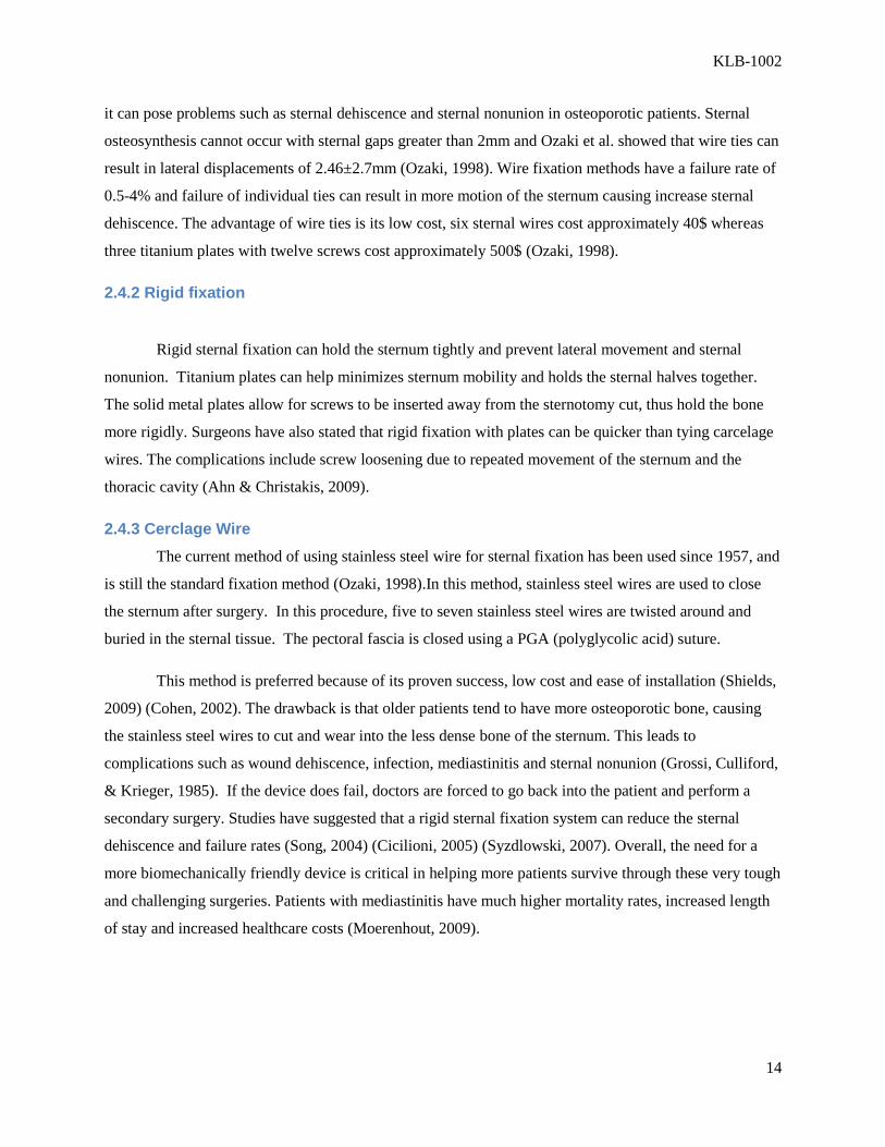
Current screw plate systems, such as the Synthes Titanium Sternal System (Synthes, Oberdorf,
Switzerland, 2007) involve both titanium plates and titanium screws within its system. Synthes also
creates a wide variety of shaped plates; H plates, X plates, T plates and straight plates that can be bent
and altered to fit sterna of all sizes. An image of the implanted Synthes plate can be seen in Figure 5. The
Synthes system also uses self-tapping locking screws that can be secured tightly onto the titanium frame.
This fixation method extends the plating system into the ribs, which can limit the compliance of the
thoracic cavity during respiration.
2.5 Screw Design Parameters
In the screw-plate system for sternal fixation, the screw serves to provide sufficient force to press
the plate against the bone. In locking systems, the screw also has separate threads on or near the head,
which serve to firmly lock the screw in place, to prevent screw loosening from occurring. Self-locking
and self-tapping screws are generally used for this system, as the self-tapping screw drills its own hole so
pre-drilling of the site is not required. The self locking component serves to fix the screw in place to limit
backing out or loosening of the screws. Usually a combination of these different screw types are used in
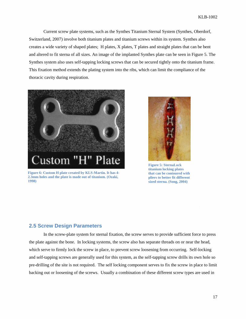
Figure 6: Custom H plate created by KLS-Martin. It has 4-
2.3mm holes and the plate is made out of titanium. (Ozaki,
1998)
Figure 5: SternaLock
titanium locking plates
that can be contoured with
pliers to better fit different
sized sterna. (Song, 2004)

KLB-1002
18
order to obtain the necessary press fit of the plate against the bone, and to provide a locking component to
limit distraction of the system.
The main components of the screw are the head, core, and threads. The head transmits the initial
torque to the core and threads, and can act as a stop when it comes in contact with the bone. The core is
the minor diameter, or the diameter of the core of the screw. The threads have a pitch and depth. The
pitch is the spacing between threads, while the depth is the distance from the core to the outer diameter of
the screw (An & Draughn, 2000). These screw parameters are altered in various screw types to help the
different screw types function better in certain situations.
2.5.1 Current types of screws used
There are several types of screws being used for fixation methods. Each one has different parameters that
allow it to function better in certain situations.
2.5.2 Cortical vs cancellous screws
The differing properties of cortical and cancellous bone lead to these different screw types.
Cortical bone is much stronger and offers high mechanical properties. In cortical screws the threads are
spaced closer together and the pitch is smaller. In cancellous screws, the threads are spaced farther apart
and the pitch is larger so the threads can compress the cancellous bone and obtain better holding
properties. It was hypothesized in previous studies that because of the high concentration of cancellous
bone in the sternum, cancellous screws would provide better fixation. This was not the case in
osteoporotic sternum though, since the thin cortical shell retains its mechanical properties but the
cancellous bone is degrades/compromised to its properties are not useful or sufficient to assist in fixation.
(Decoteau, Flannery, Hart, & Zec, 2005)
2.5.3 Standard vs Locking screws
Standard screws have an unthreaded section at the top of the screw so the screw is able to press
the plate down against the bone. Locking screws have threads around the cap that mate with threads in
the plate to lock the system in place. The press fit obtained from using standard screws is necessary to
ensure there is no gap between the plate and bone interface. The locking effect obtained from the locking
screw plate systems is also a necessary feature of the screw plate fixation system as to prevent screw
wobble and loosening. Currently using both types of screws in the screw plate system is used, but this
KLB-1002
19
increases the number of screws the surgeon must install during the screw plate installation procedure. An
ideal screw would be able to combine the properties of both these screws into a single piece screw.
2.5.4 Bicortical vs unicortical purchase
Bicortical screws are ones which go through both cortices of the bone. These are traditionally
used in many screw plate systems that are currently used. By obtaining purchase on both cortices, more
mechanical stability is obtained and better fixation is thought to occur from this. The main drawback of
bicortical screws is since they pierce the second cortical layer, they risk puncturing organs and tissues
located below the bone. This is a large concern for surgeons as when these bicortical screws are used for
sternal fixation, using a screw that is not measured properly and is too long, may result in puncturing the
heart or other tissues located below the sternum. Unicortical screws only purchase the top cortical layer.
This is viewed as safer than the bicortical purchase as the screw will not have the chance of puncturing
vital organs located below the site. The major drawback of using unicortical screws is they provide less
stable fixation. Generally bicortical screws are the preferred screw type since having sufficient holding
strength is the main concern of surgeons so the screws are measured carefully so the proper depth or
length is used.

KLB-1002
20
3.0 Project Strategy
The overall goal of the project is to design an anti-wobble screw –plate system that is
more successful than preexisting sternal screw-plate fixation systems. In order to produce a
better device, it is crucial to understand the gaps in knowledge and technology with the current
devices. With the direction of our client, Dr. Raymond Dunn of the University of Massachusetts
Medical Center in Worcester, MA, our project team was able to determine the following
objectives, functions, and constraints to develop the project.
3.1 Client Statement and Project Goals
Before starting the design process, information on sternal screw-plate systems was
gathered through recent literature and a series of interviews with our client. Based upon the
needs and wants of Dr. Dunn, a client statement was developed.
Initial Client Statement: Design and build an ideal anti-wobble screw-plate sternal
fixation device capable of reducing sternal displacement post sternotomy more
effectively than existing systems. The device must supply “rigid sternal fixation” in the
stabilization of two full hemi-sterna. A quick and easy installation and re-entry method
should be determined. The device must not endanger the patient or surgeon. Validation
testing on the device must be done using cadaverous sterna.
After research on the preexisting systems, the project team sought to design a new anti-
wobble system focusing on the interface between the device and the bone, as this is where the
project group felt was the biggest gap of knowledge in the development of a sternal fixation
device. The device would include the best characteristics of pre-existing models, while being
able to add increased stability to the device with an anti-wobble system. An ideal anti-wobble
system should be able to apply both a compressive and locking force to the plate to ensure
maximum mechanical abilities. The device chosen should be able to accomplish the intended
objectives and functions and while staying within the proposed constraint limits. The following
is a list of the overall project objectives, functions, and constraints.

KLB-1002
21
3.2 Objectives
The list of objectives below was created for the client to identify what the exact needs
and wants that an ideal device would be able to provide. The design team was able to obtain four
main objectives based upon the interviews and recent literature. Overall, the device should, safe,
provide strong stabilization of the separated halves, allow for ease of use during surgery, and
should be a simple design that allows for quick, reproducible manufacturability.
1. Device should provide rigid stabilization of sternum
a. Strong bone purchase
i. Maximize bone-plate interface
ii. Anti-wobble
b. Maintain proper alignment
c. Limits distractions- multidirectional
d. Adjustable sizes and curvature
2. Device should allow for ease of use
a. Surgery
i. Minimize installation time
ii. Minimal device parts
iii. Minimize need for specialized surgical tools
iv. Small learning curve for adaptation of surgical procedures
v. Minimal surrounding tissue damage
3. Device should be safe to use
a. For Surgeon
i. No sharp edges, etc
b. For Patient
i. Easy Removal/Re-entry
ii. Limit osteonecrosis and stress shielding
iii. Lower post-operative complications
4. Market Potential
a. Simple parts easy to manufacture
b. Surgical consistancy
KLB-1002
22
i. Able to repeatedly produce similar results
ii. Maintain mechanical integrity
c. Low material cost
d. Reproducible but still able to be specialized to individual patient
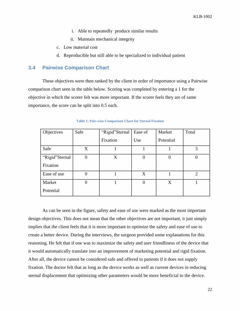
3.4 Pairwise Comparison Chart
These objectives were then ranked by the client in order of importance using a Pairwise
comparison chart seen in the table below. Scoring was completed by entering a 1 for the
objective in which the scorer felt was more important. If the scorer feels they are of same
importance, the score can be split into 0.5 each.
Table 1: Pair-wise Comparison Chart for Sternal Fixation
Objectives Safe “Rigid”Sternal
Fixation
Ease of
Use
Market
Potential
Total
Safe X 1 1 1 3
“Rigid”Sternal
Fixation
0 X 0 0 0
Ease of use 0 1 X 1 2
Market
Potential
0 1 0 X 1
As can be seen in the figure, safety and ease of use were marked as the most important
design objectives. This does not mean that the other objectives are not important, it just simply
implies that the client feels that it is more important to optimize the safety and ease of use to
create a better device. During the interviews, the surgeon provided some explanations for this
reasoning. He felt that if one was to maximize the safety and user friendliness of the device that
it would automatically translate into an improvement of marketing potential and rigid fixation.
After all, the device cannot be considered safe and offered to patients if it does not supply
fixation. The doctor felt that as long as the device works as well as current devices in reducing
sternal displacement that optimizing other parameters would be more beneficial to the device.

KLB-1002
23
3.4 Functions
After creating the list of objectives, the project team created a list of functions which
describe the means in which to maximize these objectives. There are four separate functions,
each of which plays an important role in the development the design system.
1. Mechanical
a. Rigidly holds sternum halves together
i. Minimizes sternal displacement and limits screw movement (anti-
wobble/locking)
ii. Achieves strong cortical purchase in bone
iii. Alignment is maintained throughout full sternal healing
b. Allows easy removal in emergency reentry situations
c. Increases bone-plate interaction
d. Applies compressive and locking force
2. Biological
a. Does not destroy periosteum
b. Enables bone formation and growth
c. Limits Osteonecrosis
3. Manufacturing
a. Machinability
i. Correct part sizes, not too small
ii. Allows for limited number of overall parts
iii. Ability to be sterilized
b. Increase speed of production with design simplicity
4. Surgical
a. Minimize necessary tools
b. Reduce operation time
c. Increase ease of screwing

KLB-1002
24
3.5 Constraints
The list of constraints shown below represents the parameters in which the design of
the device must follow. These constraints must be followed in order for the design of a
successful device. The device must be safe, fit within the given budget for the project, and must
be able to reduce sternal displacement as well as current devices on the market. In order to
validate the design, the device must be tested using cadaveric sterna. Time constraints such as
deadlines, deliveries and machining all must be remembered during the design process in order
to create a successful device.
1. Safety
a. Biocompatible
b. Quick and easy re-entry into chest
c. Overall safety, no sharp edges, etc.
2. Time
a. Project deadlines
b. Machine shop openings
c. Machining turn-around time
d. Parts delivery
3. Budget
a. Amount given for project
b. Cost of materials
4. Must reduce sternal displacement as well as current devices
5. Must be tested on cadaverous sterna.
With these objectives, functions, constraints and overall needs identified, a final client statement
was created.
KLB-1002
25
Final client statement:
Design and build an ideal anti-wobble screw-plate sternal fixation device capable of
reducing sternal displacement post sternotomy comparable to recent devices. The device
must supply “rigid sternal fixation” in the stabilization of two full hemi-sterna, and
should only allow for minimal amounts of screw loosening. The device must contain both
a locking and compressive mechanism that will enhance the bone-plate interface. A
quick and easy installation and re-entry method should be determined. The device must
not endanger the patient or surgeon. Overall the device should be fairly simple, easy to
use and easy to manufacture. Validation testing on the device must be done using
cadaverous sterna.
3. 6 Device Design
The goal of the project is to design a screw-plate system that not only performs as well as
current models, but can also significantly reduce screw loosening caused by the inefficiency in
other models. The lack of current devices to be able to supply both a compressive and locking
force at the bone-plate interface allows for a breadth of design ideas that could be possibly used.
Using the objectives, functions, constraints, literature and imagination, the project team was able
to create four alternative designs. Each design represents a different mechanism in which a
locking and compressive force can be applied to the bone plate interface to achieve an anti-
wobble effect. Each device was brainstormed, drawn in SolidWorks, and then analyzed by the
team for overall advantages and disadvantages. The top design was then chosen and will be used
for prototyping and testing.

KLB-1002
26
3.6.1 Design Alternative I
The first design alternative utilizes a two piece screw that arrives as one assembled part
to the surgeon as part of a plate/screw system. The design utilizes standard sternal fixation plates
and will only require one tool for surgical installation. The screw is also unicortical and of both
the compression and locking type. The two part design is essentially a screw within a screw and
functions . This alternative was designed to optimize two important functional considerations:
ease of use by the surgeon and manufacturability.
3.6.1.1 Detailed parts description
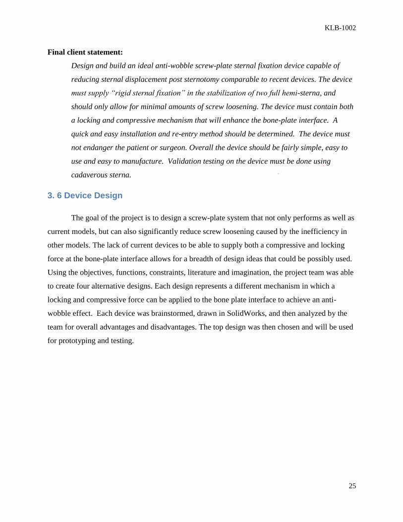
The outer screw functions identically to a compression unicortical screw with the exception of the
screw head-plate interface. As seen below in Figure 7, the outer screw has a countersunk head with radial
expansion slits around its circumference. The bottom of the countersunk hole will have receiving threads
for the internal screw. A standard unicortical thread pattern on the distal bone interfacing screw body will
be employed as well as a self-tapping and self-drilling tip. The bottom of the outer screw head will also
have a roughened surface that will interface with the bottom of the plate welling.
Figure 7: Exploded design
KLB-1002
27
The inner screw of the design will fit into the top of the outer screw with its wedge pitch being
the same angle as the outer screw’s receiving countersink, but the wedge length will extend past the top of
the outer screw. A standard Phillips head surgical tool can be used to interface with top of the internal
screw.
Figure 8: Standard fixation plate compatibility
3.6.1.2 Device Functionality
When the inner screw is mated with the female threads on the inside of the outer screw, and
gently tightened, it is pulled down into the body of the outer screw. This is the state of the device at which
the surgeon will receive it. The screw is then inserted into the plate and bone through normal surgical
procedure. When the screw has reached a tightness determined by the surgeon for compression fit of the
plate to the bone, the surgeon will exert a downward force to engage the roughened outer screw head’s
bottom surface with the fixation plate’s well surface. This will create enough of a frictional force to allow
the inner screw to continue to rotate into the outer screw internal body (and without stripping the bone),
thus creating an outward wedging force on the outer screw head. The expansion slits will allow the head
of the outer screw to expand into the walls of the plate, causing a force induced locking mechanism that
will hold the screw tightly at the plate interface. Figure 8 shows a cross-sectional view of the design that
details the forces produced by the inner screw on the outer screw.
KLB-1002
28
Figure 9: Cross sectional view of assembled design
3.6.1.3 Device Advantages/Disadvantages
This two part screw design aims to allow for the functional requirements of rigid sternal fixation,
while optimizing the ease of use for the surgeon and manufacturability. Based on interviews with the
client it was determined that the design needed to be one piece and easy to install for a cardiac surgeon.
This design is very advantageous to that respect because it allows for the surgeon to utilize the screw
exactly how he would use a normal compression screw. The only added motion required for locking is a
downward press that engages the rough bottom surface. This design requires one tool and a very minimal
learning curve for the surgeon. The second advantage is the simplicity of the design that will facilitate
manufacturing and lower costs. A standard inner screw could be utilized in the design and the outer screw
could even be machined from a standard screw itself.
The disadvantages of this design are related to the material design and emergency removal
considerations. First, if both parts are made out of titanium, the force required to outwardly splay the
screw head into the also titanium plate may be too high for the surgeon to exert by hand. Second, the

KLB-1002
29
emergency removal of the screw will most likely require a second tool that can hold the outer edge of the
outer screw while the inner screw is removed. The outer screw could then be backed out safely.
Figure 10: Complete screw and plate model
KLB-1002
30
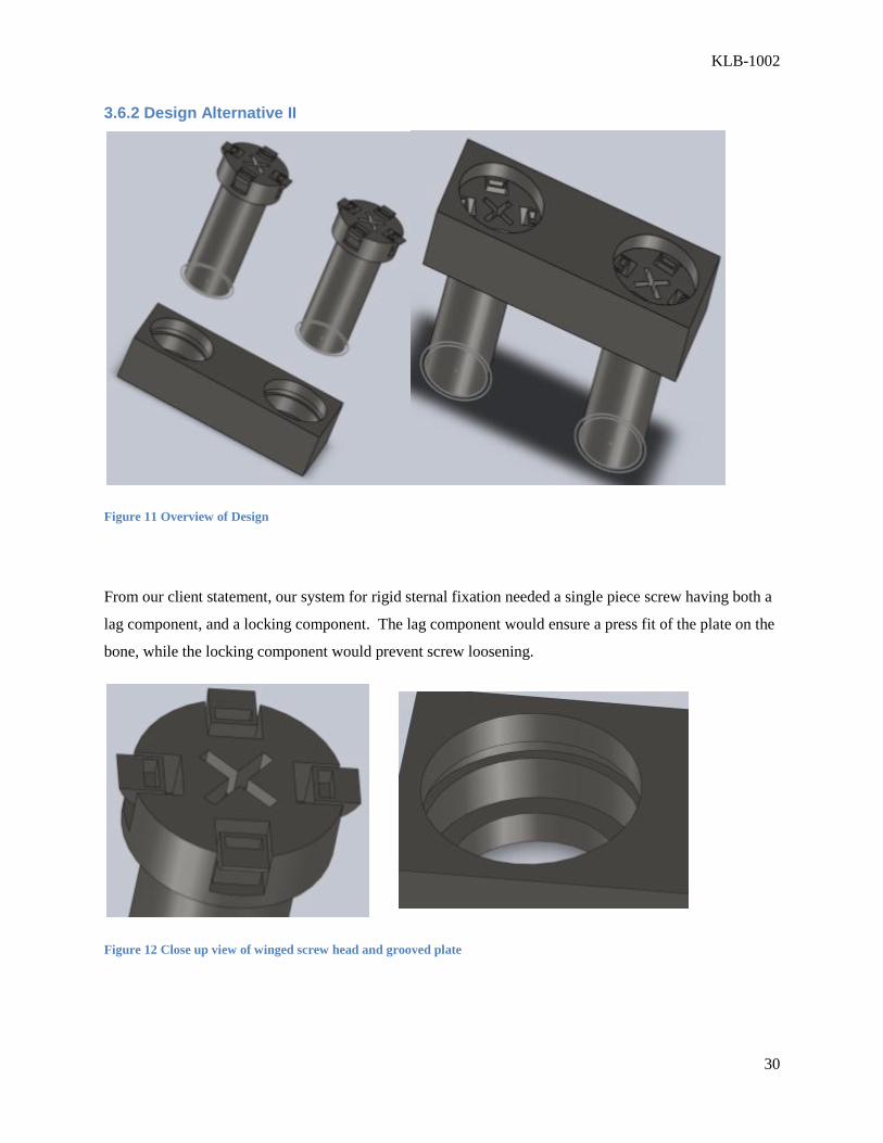
3.6.2 Design Alternative II
Figure 11 Overview of Design
From our client statement, our system for rigid sternal fixation needed a single piece screw having both a
lag component, and a locking component. The lag component would ensure a press fit of the plate on the
bone, while the locking component would prevent screw loosening.
Figure 12 Close up view of winged screw head and grooved plate

KLB-1002
31
In this design alternative, the locking mechanism involves 4 wings that are pinched back during
installation. This can either be done with a special tool or the screw can be preassembled with the wings
pinched back, having a clip to hold them in place. The screw then functions as a standard screw during
surgery. Once the press fit is obtained, the user would remove the clip holding the wings back and they
would lock into place. If the screws needed to be removed, the wings could be pinched back using a
specialized tool, and remove the locking mechanism so the system could be uninstalled.
Figure 13 Cross Section view of system after installation
Advantages of this design are it uses a single piece screw, has an emergency release mechanism, would
be simple to use, and no similar designs were found in patent searches. Disadvantages include
manufacturability as these screws would be millimeters in diameter, and the necessity of a specialized
tool to pinch the wings back during installation.
3.6.3 Design Alternative III
This design alternative is a screw-plate system with locking wing clips on the screw. The
three-piece screw is preassembled and the head can rotate freely to lock into the plate. The plate
has two screw holes, one for each half of sternum, and a series of notched sides for the locking
cap to fit into.
The three-piece screw consists of a screw head, rotating middle piece with wing clips to
lock into the plate, and a screw shaft that will go in to the sternum, as seen in the figure below.
The screw shaft is 2.3mm in diameter while the cap is 3.0mm in diameter. The screw will be

KLB-1002
32
unicortical, so varying screw lengths will be used. As the top piece is screwed down, it will
tighten with the bottom shaft piece and lock the whole system into the screw. The screw system
will be 3 pieces but come pre-preassembled. The middle piece needs to be rotated by the surgeon
so the wings can lock and be tightened against the plate.
Figure 14: Schematic of three piece screw.

KLB-1002
33
Figure 15: Exploded cross-section view
The advantage of this design is the increased stability from the three points of contact to
the screw; the wings, threaded plate, and the bone. This will minimize the sawing motion created
by the screw. The notches allow for different levels of screw entry based on the contour of the
sternum, if there is a curvature of the bone, the plate can’t get close to the bony surface. The
plate designed used is not limited to a straight plate; an X-plate could offer much more stability
of the entire system. This screw system is also a novel anti-wobble design so there is a lot of

KLB-1002
34
market potential. The disadvantage of this system is the complexity of the screw parts. The
pieces are very small and could prove hard to manufacture. Because our final implantable device
will be titanium, the wing clips need to be compliant enough to snap in to each individual groove
in the plate.
Figure 16:3D model of the plate interface.
KLB-1002
35
3.6.4 Design Alternative IV
The next design alternative involves a one piece, two part screw in which the top of the screw is
able to be locked and wedge into place due to its shape fitting properties.
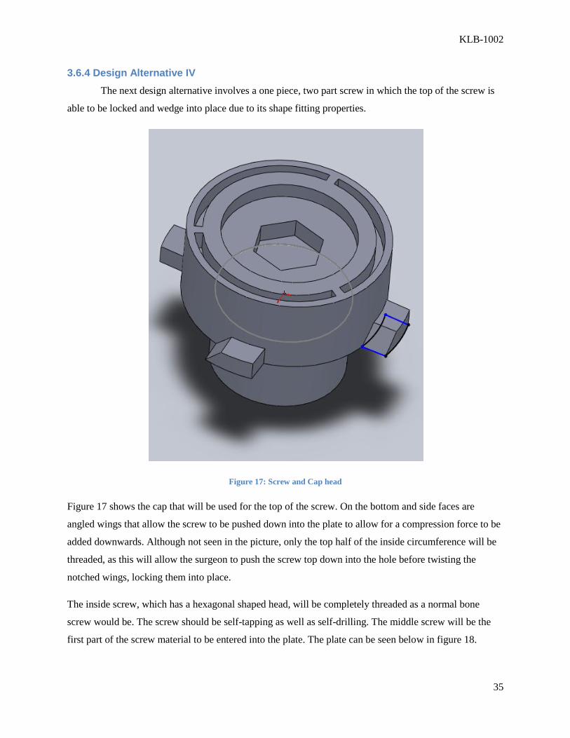
Figure 17: Screw and Cap head
Figure 17 shows the cap that will be used for the top of the screw. On the bottom and side faces are
angled wings that allow the screw to be pushed down into the plate to allow for a compression force to be
added downwards. Although not seen in the picture, only the top half of the inside circumference will be
threaded, as this will allow the surgeon to push the screw top down into the hole before twisting the
notched wings, locking them into place.
The inside screw, which has a hexagonal shaped head, will be completely threaded as a normal bone
screw would be. The screw should be self-tapping as well as self-drilling. The middle screw will be the
first part of the screw material to be entered into the plate. The plate can be seen below in figure 18.

KLB-1002
36
Figure 18: Plate design
Once the middle screwed is screwed in, and the cap has reached the top of the plate, the wings should be
arranged in a fashion so that they fit the shape of the hole exactly. Once down to the bottom of the
grooves, the cap can then be rotated and locked into the track that is located circumferentially around the
bottom of the plate. The track will decrease is size by a slight angle, allowing the tapered edges of the
wings to be wedged into the plate.
There are several limitations with a device like this. First of all, the plate holes are already very small and
it would be very hard to manufacture such detailed plate holes. There is also the limitation in the
possibility that the surgeon will not be able to get a full compressive fit before rotating the cap creating
the locking mechanism. Another disadvantage is shown by the fact that more than one tool will be
necessary to screw down the different parts. This will make it necessary to make extra tools, which is not
cost effective. Overall the device has a strong theoretical concept, but does not seem to be able to be used
in a practical manner.
KLB-1002
37
3.7 Experimental Design
The project group designed an anti-wobble screw-plate system but the screw loosening
performance needs to be compared to a standard unicortical screw-plate system to successfully validate
the design. The goal of the experimental testing is to show a lower displacement of the screw-plate system
after uniaxial cyclic loading tests in sawbone sterna and human sterna. A screw plate system will be tested
on a single section of sternum to generate multiple data sets and while conserving testing specimen.
Uniaxial cyclic loading will first be performed on sawbone sterna in order to obtain preliminary results
for each screw-plate system and optimize the experimental protocol. After screw-loosening data is
obtained in sawbone sterna, the cyclic loading tests will be repeated on human sterna. Results from
human sterna testing will help validate the success of our anti-wobble design.
3.7.1 Methodology
The following methods were used for validation testing for the anti-wobble design. An Instron
Electropuls E-1000 uniaxial testing device was used to perform cyclic loading tests to simulate respiratory
forces. The Instron Console and Wavematrix programs were used to set the testing parameters including:
force, frequency, and number of cycles. The program recorded displacement data over the testing time.
Measuring the displacement produced from the low force cyclic loading will help assess the
performance of the screw-plate system. An extensomer was used to measure the displacement locally to
remove any noise from the potting and fixation methods. A schematic of the testing can be seen in Figure
18.

KLB-1002
38
Figure 19: Schematic of testing setup
KLS Martin titanium mandibular reconstruction plates were used with 2.3mm cortical titanium
screws. Due to manufacturing complications and time constraints, initial testing was performed using a
similar anti-wobble device designed by John Dieselman. This device consisted of a two piece screw and
cap system to achieve the delayed locking effect, similar to our one piece system. As seen in Figure 19,
the anti-wobble system used for initial validation testing consisted of a thicker plate to accommodate the
screw cap and used the same 2.3mm standard screw.
Figure 20: Cap and plate for anti-wobble system on the left. Screw for both systems in the middle. Standard plate on the
right.
2m
m

KLB-1002
39
Initial testing was performed in Sawbone Sternal models. This testing was used to assess the
testing protocol and make any necessary adjustments. Also this served as initial proof of concept testing
to validate the “locking” mechanism before moving on to further validation in cadaveric sternum. In this
low force cyclic testing, a 50N force transducer was used to apply a force of 50N at a frequency of 2Hz
for 15,000 cycles. Each test took approximately two and a half hours.
Prior to testing, the sawbone sternal models were bisected laterally, and sectioned off by rib pairs.
Two tests were performed on each piece of sawbone. For proper pairing, one standard system and one
anti-wobble system were tested on each sawbone piece. Prior to testing, the sawbone piece was potted in
a modified 1 inch PVC endcap using epoxy. Samples were offset to allow for proper uniaxial alignment
in the Instron machine. Epoxy polymerization took approximately 30 minutes. After this, the sternal
piece was rigidly secured in the cap. Then the sample was fixed into the gripper of the Instron using a
custom made grip to grasp the plate. The setup can be seen in Figure 20.
Figure 21: Actual instron testing setup.
KLB-1002
40
3.7.2 Instron Electropuls Setup
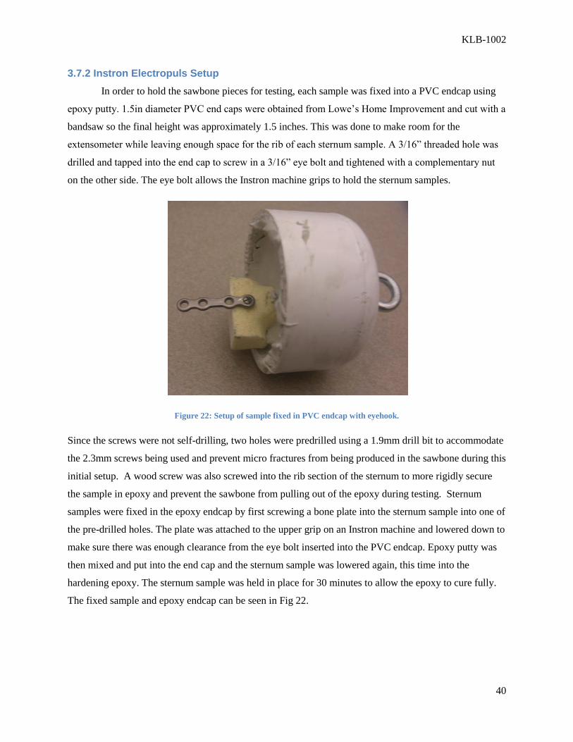
In order to hold the sawbone pieces for testing, each sample was fixed into a PVC endcap using
epoxy putty. 1.5in diameter PVC end caps were obtained from Lowe’s Home Improvement and cut with a
bandsaw so the final height was approximately 1.5 inches. This was done to make room for the
extensometer while leaving enough space for the rib of each sternum sample. A 3/16” threaded hole was
drilled and tapped into the end cap to screw in a 3/16” eye bolt and tightened with a complementary nut
on the other side. The eye bolt allows the Instron machine grips to hold the sternum samples.
Figure 22: Setup of sample fixed in PVC endcap with eyehook.
Since the screws were not self-drilling, two holes were predrilled using a 1.9mm drill bit to accommodate
the 2.3mm screws being used and prevent micro fractures from being produced in the sawbone during this
initial setup. A wood screw was also screwed into the rib section of the sternum to more rigidly secure
the sample in epoxy and prevent the sawbone from pulling out of the epoxy during testing. Sternum
samples were fixed in the epoxy endcap by first screwing a bone plate into the sternum sample into one of
the pre-drilled holes. The plate was attached to the upper grip on an Instron machine and lowered down to
make sure there was enough clearance from the eye bolt inserted into the PVC endcap. Epoxy putty was
then mixed and put into the end cap and the sternum sample was lowered again, this time into the
hardening epoxy. The sternum sample was held in place for 30 minutes to allow the epoxy to cure fully.
The fixed sample and epoxy endcap can be seen in Fig 22.

KLB-1002
41
Figure 23: Custom grip to hold bone plate.
Because there is very little surface area to hold the bone plate, a custom grip was designed to
withstand 15,000 cycles of testing. Two aluminum plates were used to rigidly secure the bone plate
without. Four holes were drilled and tapped into the plates and four 8-32 hex screws were used to tighten
the aluminum plates with the bone plate in between (Fig 23).
In order to set up the custom grip and fixed sternum sample, the bone plate is first inserted into
the custom grip and tightened. Then a pilot hole is drilled into the sternum sample and the bone plate is
secured onto the sternum sample with a single screw. The entire set up is then carefully placed into the
Instron grips making sure the plate is parallel with the force transducers. Finally the Instron grips are
tightened and testing begins. An image of the testing setup can be seen in Fig 20.
3.7.3 Testing Parameters
Instron Console and Wavematrix were used to program the cyclic testing for the Instron
Electropuls machine. A 50Nload transducer was used and machine safety limits were set to 51N with the
Instron Console program. A cyclic load testing method was programmed with Wavematrix. The test
began with a 5-second ramping phase to set the sample load to zero. Cyclic testing starts when the
samples are loaded from 0 to 50N, and then repeated for 15,000 cycles at a rate of 2Hz. Testing ends
when the sample fails or 15,000 cycles are completed.
3.7.4 Modifications for Cadaveric Sternum Testing
A few modifications were made to the testing protocol for testing using cadaveric sternum. The
human sternum was sufficiently weaker and had more irregular mechanical properties compared to the
KLB-1002
42
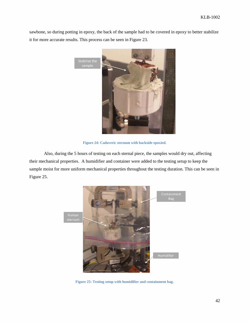
sawbone, so during potting in epoxy, the back of the sample had to be covered in epoxy to better stabilize
it for more accurate results. This process can be seen in Figure 23.
Figure 24: Cadaveric sternum with backside epoxied.
Also, during the 5 hours of testing on each sternal piece, the samples would dry out, affecting
their mechanical properties. A humidifier and container were added to the testing setup to keep the
sample moist for more uniform mechanical properties throughout the testing duration. This can be seen in
Figure 25.
Figure 25: Testing setup with humidifier and containment bag.
KLB-1002
43
4.0 Manufacturing
4.1 Prototype Manufacturing
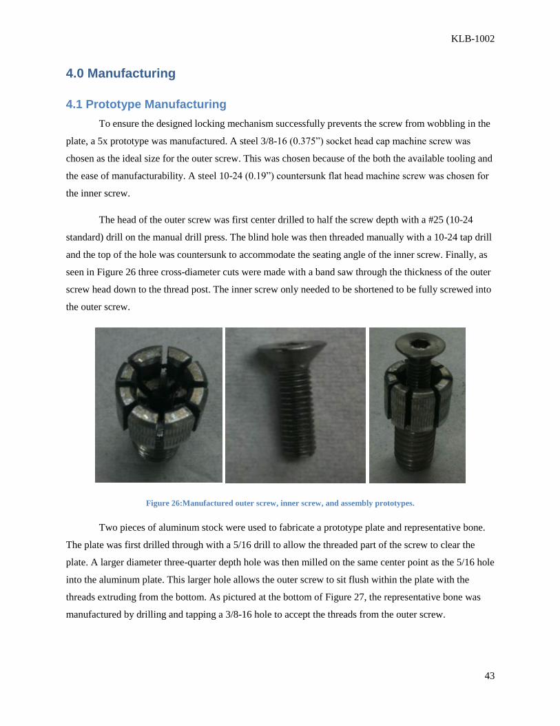
To ensure the designed locking mechanism successfully prevents the screw from wobbling in the
plate, a 5x prototype was manufactured. A steel 3/8-16 (0.375”) socket head cap machine screw was
chosen as the ideal size for the outer screw. This was chosen because of the both the available tooling and
the ease of manufacturability. A steel 10-24 (0.19”) countersunk flat head machine screw was chosen for
the inner screw.
The head of the outer screw was first center drilled to half the screw depth with a #25 (10-24
standard) drill on the manual drill press. The blind hole was then threaded manually with a 10-24 tap drill
and the top of the hole was countersunk to accommodate the seating angle of the inner screw. Finally, as
seen in Figure 26 three cross-diameter cuts were made with a band saw through the thickness of the outer
screw head down to the thread post. The inner screw only needed to be shortened to be fully screwed into
the outer screw.
Figure 26:Manufactured outer screw, inner screw, and assembly prototypes.
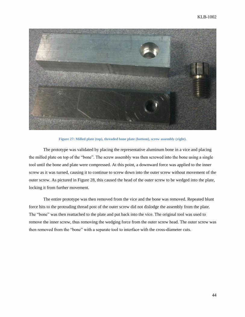
Two pieces of aluminum stock were used to fabricate a prototype plate and representative bone.
The plate was first drilled through with a 5/16 drill to allow the threaded part of the screw to clear the
plate. A larger diameter three-quarter depth hole was then milled on the same center point as the 5/16 hole
into the aluminum plate. This larger hole allows the outer screw to sit flush within the plate with the
threads extruding from the bottom. As pictured at the bottom of Figure 27, the representative bone was
manufactured by drilling and tapping a 3/8-16 hole to accept the threads from the outer screw.
KLB-1002
44
Figure 27: Milled plate (top), threaded bone plate (bottom), screw assembly (right).
The prototype was validated by placing the representative aluminum bone in a vice and placing
the milled plate on top of the “bone”. The screw assembly was then screwed into the bone using a single
tool until the bone and plate were compressed. At this point, a downward force was applied to the inner
screw as it was turned, causing it to continue to screw down into the outer screw without movement of the
outer screw. As pictured in Figure 28, this caused the head of the outer screw to be wedged into the plate,
locking it from further movement.
The entire prototype was then removed from the vice and the bone was removed. Repeated blunt
force hits to the protruding thread post of the outer screw did not dislodge the assembly from the plate.
The “bone” was then reattached to the plate and put back into the vice. The original tool was used to
remove the inner screw, thus removing the wedging force from the outer screw head. The outer screw was
then removed from the “bone” with a separate tool to interface with the cross-diameter cuts.

KLB-1002
45
Figure 28: Validation of the locking mechanism. Inner screw has been tightened and the head of the outer screw has
engaged the plate. After removal of the bone plate from below, blunt forces to the screw thread post did not dislodge the
part.
4.2 Production Model Manufacturing
The manufacturing of an implantable screw plate system that ensures rigid, locking sternal
fixation would be complicated from raw materials. The project team decided to modify a currently
available sternal fixation system through micromachining. A 2.3mm KLS Martin mandibular bone screw,
seen in Figure 29, was chosen based on its head design. The screw has a flat circumferential edge that will
mimic the wedging action of the prototype. The plate supplied with this particular KLS Martin sternal
system is a standard non-locking bone plate and can be seen in Figure 31.
Figure 29: KLS Martin screw adjacent to a nickel (left) and a close-up of the thread pattern and head profile (right).

KLB-1002
46
Figure 30: A CAD model of the miniaturized assembly.
4.2.1 Machining Titanium
The KLS Martin bone screws are a medical grade titanium alloy, a difficult material to work with.
Titanium has a low thermal conductivity, making heat buildup in the tooling an issue. Stronger tooling
with advanced flute design allows efficient removal of material without sacrificing cutting precision.
Many titanium compatible tool bits are made of solid carbide because of its resistance to failure at higher
temperature. Coatings can also be applied to the carbide tools to increase reliability. Titanium aluminum
nitride coated carbide tools (grade F8 or B8 carbide) are an example of this and are the tool material that
will be used for our machining purposes.
Figure 31: KLS Martin mandible bone plate.

KLB-1002
47
4.2.2 End Milling
Before milling can be started, a custom grip to rigidly hold the titanium bone screw perfectly
centered and without damaging the screw threads must be used. A circular aluminum slug will be used as
a holder for the screw to allow a rigid grip of the screw necessary for machine milling. Any part vibration
or wobbling during machining can lead to catastrophic failure of a tool and possibly the screw itself. The
aluminum slug will also allow for accurate center probing of the screw, ensuring that the milling
operations are done at the exact center. To safely drill the titanium bone screw to the desired diameter and
depth, a carbide end mill bit is the preferred tool. A standard centerplunge method will be used with a
3/64” four-flute solid carbide end mill to incrementally remove small amounts of the titanium. This
approach minimizes tooling contact time with the screw, reducing friction and cutting temperatures.
4.2.3 Single Profile Thread Mill
Single Profile Thread Mills (SPTMs) are the ideal thread cutting tool for titanium applications.
They are made of solid carbide and employ multiple flutes with a single thread form on the bit. This
allows a significant reduction in side cutting pressure on the tool, which when tapping titanium, is a
significant concern. An 0-80 internal thread will be cut into the end milled hole of the bone screw. A
CNC program provided by Scientific Cutting Tools, the manufacturer of the SPTM, will allow proper
cutting of titanium.
4.2.4 Wire Electrical Discharge Machining
Wire electrical discharge machining (wEDM) will be used in order to make the specialized, high
accuracy cuts into the small screw head. In this machining process, a very thin piece of brass wire is
electrically charged and used to cut into the titanium. The cutting guides are accurate up to 0.004 mm.
The smallest cuts possible use a 0.1mm wire, creating a 0.12 mm cut. For overall industrial
manufacturing, the most economically and time efficient wire is a 0.25 mm creating a .335 mm cut. Over-
cutting occurs due to the sparking that is created, causing erosion. Overall, the additional amount cut out
due to erosion is sufficiently predictable and will be compensated for. Wire diameters can be created as
small as 20 micrometers. The overall energy necessary per pulse is relatively low and will not affect the
mechanical properties of the material.
4.2.5 Manufacturing Procedure
The procedure for the manufacturing of the device is a repeatable process that can be applied to
commercial batch manufacturing of the screws. This is important to the feasibility of the device both in
cost and manufacturability.
KLB-1002
48
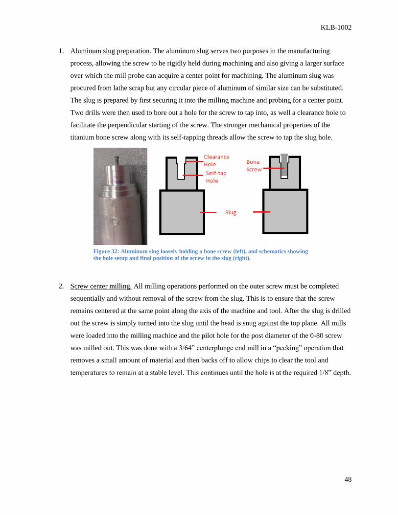
1. Aluminum slug preparation. The aluminum slug serves two purposes in the manufacturing
process, allowing the screw to be rigidly held during machining and also giving a larger surface
over which the mill probe can acquire a center point for machining. The aluminum slug was
procured from lathe scrap but any circular piece of aluminum of similar size can be substituted.
The slug is prepared by first securing it into the milling machine and probing for a center point.
Two drills were then used to bore out a hole for the screw to tap into, as well a clearance hole to
facilitate the perpendicular starting of the screw. The stronger mechanical properties of the
titanium bone screw along with its self-tapping threads allow the screw to tap the slug hole.
2. Screw center milling. All milling operations performed on the outer screw must be completed
sequentially and without removal of the screw from the slug. This is to ensure that the screw
remains centered at the same point along the axis of the machine and tool. After the slug is drilled
out the screw is simply turned into the slug until the head is snug against the top plane. All mills
were loaded into the milling machine and the pilot hole for the post diameter of the 0-80 screw
was milled out. This was done with a 3/64” centerplunge end mill in a “pecking” operation that
removes a small amount of material and then backs off to allow chips to clear the tool and
temperatures to remain at a stable level. This continues until the hole is at the required 1/8” depth.
Figure 32: Aluminum slug loosely holding a bone screw (left), and schematics showing
the hole setup and final position of the screw in the slug (right).

KLB-1002
49
Figure 33: Schematic showing the progression of material removal by the centerplunge endmill.
3. Screw thread milling. Directly after the pilot hole is milled the tool is switched within the
machine to the single profile thread mill. The thread mill program was provided by the tool
manufacturer and cuts a 0-80 thread into the interior of the pilot hole from bottom to top. It
accomplishes through a helical cutting pattern up the circumferential edge of the hole.
Figure 34: Screw and Thread mill close-up.
Figure 35: Schematic of the cutting of the 0-80 thread within the outer screw pilot hole.

KLB-1002
50
4. Expansion cuts. The extension of the already present Philips head cut down the full length of the
outer screw head was completed using the wire EDM procedure (Roger Tool & Die Co.,
Worcester, MA). This procedure allowed for very accurate cuts that did not damage any of the
screw or previous operations work.
Figure 36: Close-up view of expansion slits that were cut using wire EDM.
Table 2: Itemized manufacturing procedure
# Part Operation Tool Description
0 Aluminum slug Probe Probe bore Find center
1 Aluminum slug Mill 0.076” drill bit Hole for self-tap
2 Aluminum slug Mill 0.089” drill bit Clearance hole
3 Outer screw Mill
3/64” 4-flute
centerplunge
end mill
Pre-tapping hole
4 Outer screw Mill 0-80 Thread mill Tapping of hole
5 Outer screw Cut EDM 2 full diameter
expansion cuts
1mm

KLB-1002
51
4.2.6 Assembly
With the finished outer screw complete, the unmodified 0-80 screw was turned into the outer
screw. The pre-assembled screws can be seen in Figure 37. Final assembly of the part will require that the
inner screw be turned down until it makes contact with the outer screw head but does not splay any of the
expansion edges outward. The assembled screws can be seen in Figure 38. This is the state at which we
will be installing the screw and also how the surgeon will ultimately receive it.
Figure 37: Pre-assembled outer screw and inner screw.
Figure 38: Assembled screw-plate system.

KLB-1002
52
5.0 Results
5.1 Sawbone Sternum Verification
The experimental procedures were first performed on polyurethane sawbone sternum segments as
stated in the methodology. The goal of this experiment was to compare the screw-loosening of the
standard vs anti-wobble plating systems. Standard and anti-wobble tests were paired to each sternum
segment and a total of 4 tests were performed in 2 groups: standard screw-plate system with n=2 and anti-
wobble screw-plate system with n=2. The peak displacements during cyclic testing are summarized in
Table 2.
Table 3: Peak screw displacement in sawbone
Standard (n=2) Anti-Wobble (n=2)
10 Cycles 0.33mm 0.18mm
100 Cycles 0.42mm 0.19mm
1000Cycles 0.50mm 0.20mm
15000 Cycles 0.57mm 0.20mm
As seen from the table, the peak displacement for the anti-wobble screw plate system is much
lower than the standard screw-plate system. The final displacement after 15,000 cycles for the anti-
wobble was 0.20mm compared to 0.57mm for the standard. The anti-wobble system had 65% less
displacement than the standard screw system. The anti-wobble system showed low displacements at 10,
100 and 1,000 cycles when compared to the standard system. Throughout the test, the anti-wobble system
showed little change in displacement throughout the 15,000 cycles while the displacement for the
standard system steadily increased.
A graph displaying the average displacement for the standard and anti-wobble system can be seen
in Figure 39. It can be seen from the graph that the standard screw-plate system takes about 1,000 cycles
before the system starts to plateau at a displacement of ~0.4mm. In comparison, the anti-wobble system
plateaus at ~100 cycles and the displacement stays steady at ~0.18mm. It can be concluded that after
15,000 cycles, the anti-wobble screw-plate system greatly minimized the screw displacement in the
sawbone samples. Testing proceeded to human cadaveric sternum samples in order to provide more
clinically relevant data.
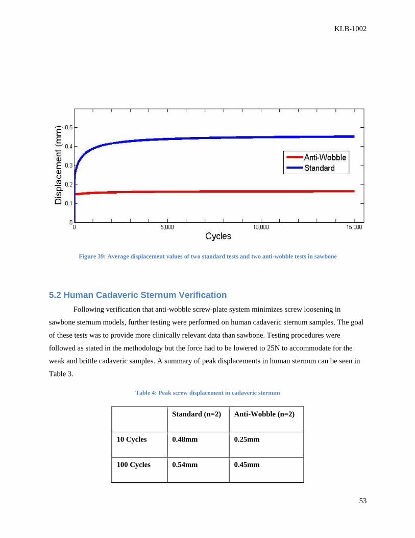
KLB-1002
53
Figure 39: Average displacement values of two standard tests and two anti-wobble tests in sawbone
5.2 Human Cadaveric Sternum Verification
Following verification that anti-wobble screw-plate system minimizes screw loosening in
sawbone sternum models, further testing were performed on human cadaveric sternum samples. The goal
of these tests was to provide more clinically relevant data than sawbone. Testing procedures were
followed as stated in the methodology but the force had to be lowered to 25N to accommodate for the
weak and brittle cadaveric samples. A summary of peak displacements in human sternum can be seen in
Table 3.
Table 4: Peak screw displacement in cadaveric sternum
Standard (n=2) Anti-Wobble (n=2)
10 Cycles 0.48mm 0.25mm
100 Cycles 0.54mm 0.45mm
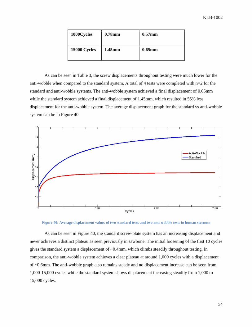
KLB-1002
54
1000Cycles 0.78mm 0.57mm
15000 Cycles 1.45mm 0.65mm
As can be seen in Table 3, the screw displacements throughout testing were much lower for the
anti-wobble when compared to the standard system. A total of 4 tests were completed with n=2 for the
standard and anti-wobble systems. The anti-wobble system achieved a final displacement of 0.65mm
while the standard system achieved a final displacement of 1.45mm, which resulted in 55% less
displacement for the anti-wobble system. The average displacement graph for the standard vs anti-wobble
system can be in Figure 40.
Figure 40: Average displacement values of two standard tests and two anti-wobble tests in human sternum
As can be seen in Figure 40, the standard screw-plate system has an increasing displacement and
never achieves a distinct plateau as seen previously in sawbone. The initial loosening of the first 10 cycles
gives the standard system a displacement of ~0.4mm, which climbs steadily throughout testing. In
comparison, the anti-wobble system achieves a clear plateau at around 1,000 cycles with a displacement
of ~0.6mm. The anti-wobble graph also remains steady and no displacement increase can be seen from
1,000-15,000 cycles while the standard system shows displacement increasing steadily from 1,000 to
15,000 cycles.

KLB-1002
55
Human cadaveric sternum testing showed that the anti-wobble mechanism applies well to a
clinically relevant sample. The cadaveric sternum samples are osteoporotic and have an outer cortical
shell and inner cancellous region while the sawbone models have perfectly uniform density throughout.
The results show that the anti-wobble mechanism can help achieve 55% less displacement and can help
osteoporotic patients who are experiencing complications during the healing process after sternal closure.
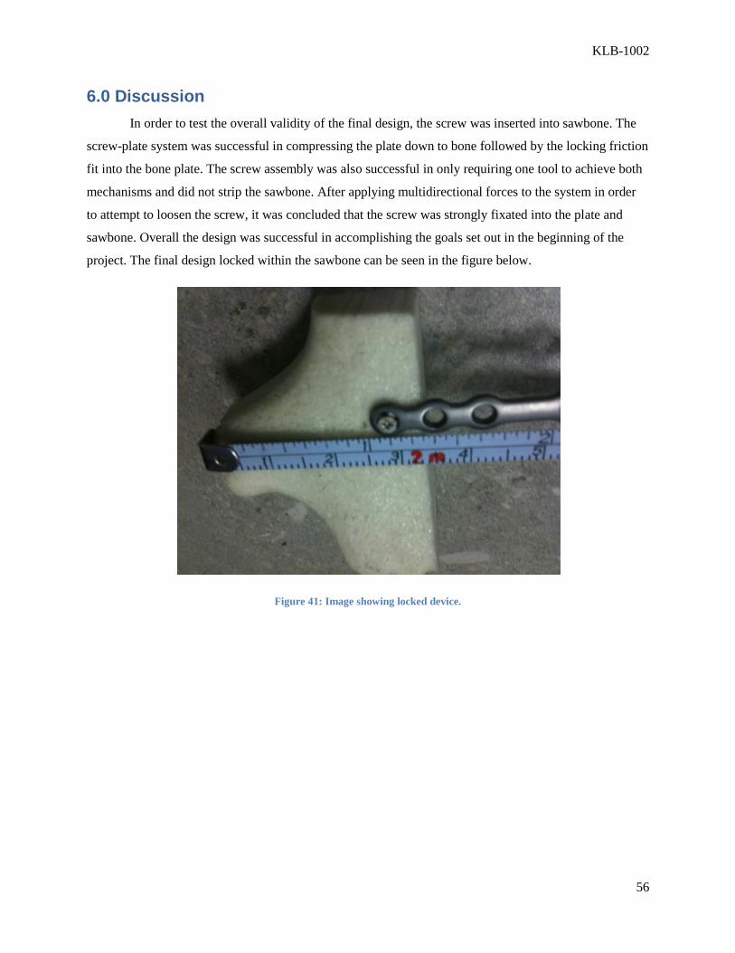
KLB-1002
56
6.0 Discussion
In order to test the overall validity of the final design, the screw was inserted into sawbone. The
screw-plate system was successful in compressing the plate down to bone followed by the locking friction
fit into the bone plate. The screw assembly was also successful in only requiring one tool to achieve both
mechanisms and did not strip the sawbone. After applying multidirectional forces to the system in order
to attempt to loosen the screw, it was concluded that the screw was strongly fixated into the plate and
sawbone. Overall the design was successful in accomplishing the goals set out in the beginning of the
project. The final design locked within the sawbone can be seen in the figure below.
Figure 41: Image showing locked device.

KLB-1002
57
Figure 42: Side view of the screw.
In this project, the anti-wobble concept developed in previous work was redesigned and
manufactured on a clinically applicable scale. The anti-wobble concept was compared to standard non-
locking screw plate systems. Due to manufacturing and time constraints, initial validation testing was
performed using a similar anti-wobble screw-plate system. Through initial testing in sawbone, and final
testing in cadaveric sterna, the results showed that the anti-wobble system minimized screw loosening.
Due to manufacturing difficulties, the design was made after the anti-wobble validation testing in
cadaveric sterna. The locking mechanism was shown to work properly in sawbone. Our initial goal of
designing a screw plate system to minimize screw loosening was met.
As seen from the results section, during sawbone testing the average displacement after 15,000
cycles of loading for the standard and anti-wobble screws were respectively 0.57mm and 0.20mm. In
cadaveric sterna the anti-wobble screws again significantly outperformed the standard screws as the
displacement of the standard and anti-wobble screws were respectively 1.45mm and 0.65mm. These
results look very promising as the standard screw plate system used for comparison is one of the major
types available commercially that is being used in the clinic.
When looking at the effectiveness of our device in comparison to other currently available
systems, the differences are more difficult to see. Current systems such as the Talon by KLS Martin and
the Titanium screw plate system by Synthes exhibit very low displacements, similar to those displayed by
the anti-wobble system. The Synthes system relies on obtaining better fixation by using screws across the

KLB-1002
58
ribs to gain more support. While this method is effective in holding the sterna rigidly, it limits chest
movement during respiration and involves the use of a lot more screws, increasing surgery time. The
Talon by KLS Martin is effective at rigidly holding the sterna, but the device is complicated and
expensive, and is still not optimized for osteoporotic bone.
The anti-wobble system designed in this project helps improve fixation and lower displacement
while overcoming or avoiding the problems associated with other currently available devices. The anti-
wobble system showed much lower displacement compared to the standard screw systems, achieving the
lower displacement achieved in the KLS Martin and Synthes devices. Our system also maintained the
simplicity of the standard screw for ease of use by surgeons and keeping operating times to a minimum.
Some major limitations of our design involved parameters that would need to be optimized better
for proper functions of our delayed locking mechanism. The outer screw slits need to be redesigned to
splay out easier and remain mechanically sound so they don’t break off. The inner screw would need to
be made of titanium and be made to medical grade tolerances as seen in the outer screw used. This would
help prevent the inner screw head from stripping during locking, so sufficient force could be applied to
achieve the locking mechanism.
The force required to splay the outer screw was much greater than expected. Because of this, a
specialized tool would need to be developed to hold the outer screw during the final locking turn, to
protect the bone from being stripped from the excessive force.
Overall we demonstrated proof of concept for our design, that the design is feasible on the
clinical scale and would lower displacement between sternal halves caused by screw loosening. The
device is currently not ready for clinical use as some redesign would be required to fix the previously
mentioned limitations.
6.1 Sawbone Model
During the testing with cadaveric sternum and after reviewing the results, it was apparent that the
sawbone models used for initial testing are not an accurate representation of real bone. The polyurethane
sawbone models resemble the sternum in shape, but their uniform density and properties don’t properly
account for the properties present in real bone. While the sawbone was able to withstand testing at 50N,
the 50N loading tore through the real bone after less than 100 cycles. Real bone has an irregular density
and surface, and mainly is much weaker mechanically than the sawbone models. A lower density
sawbone model with a hardened shell would better simulate the osteoporotic human bone used in testing.
Sawbone is mainly used due to its low cost and ease, but using real bone gives more relevant data.
KLB-1002
59
6.2 Anti-Wobble System
The initial sawbone testing validated our design concept as the anti-wobble screw showed less
initial loosening, as well as significantly lower final displacement compared to the standard screw. The
difference became more apparent during human sternum testing as the screw wobble and loosening was
much more visible due to the weaker properties of the bone. During this testing, the anti-wobble system
was able to plateau and maintain a displacement under 1mm while the standard screw never truly
plateaued and the displacement steadily increased during testing. The lowered displacement observed in
the anti-wobble system can be attributed to both the compression fit obtained between the plate and bone,
as well as the locking mechanism between the screw and the plate.
6.3 Manufacturing
One of the major advantages of this device is that it does not require any new overall
infrastructure, as the device is created through modifying current bone screws. The tools and technologies
used to manufacture these screws would much be much easier on a commercial level. Commercial
manufactures would most likely be able to use milling and EDM, just as the project group had. One of the
toughest parts of the project was not having any manufacturing experience. There were several times
when the project group had to reach out to outside agencies to complete the project. Out sourcing to wire
EDM and thread mill companies brought up the overall cost of the product.
6.4 Future Recommendations
For future testing, we recommend using cadaveric sternum to attain statically significant results.
Due to time constraints, our sample size of only four is not sufficient to make concrete conclusions but it
does show promise for the concept and design. Further testing using full sternum should also be done for
further validation.
While our design seemed to work well in the prototype, when moving to real bone, it is much
easier to strip the bone. The final turn to lock the screw after the compression fit is obtained might risk
striping the bone depending on the force required. A specialized tool would need to be developed to hold
the outer screw in place during the final locking turn of the inner screw to prevent this striping from
occurring and protect the bone.
While our design was shown to successfully splay out the head, wider expansion slots can
minimize the force required to splay out the head of the outer screw. A redesigned screw model in

KLB-1002
60
comparison to the original design is shown in the figure below. From a manufacturing standpoint, this
modification would use the same manufacturing techniques but requires a thicker wire EDM cut.
Figure 43: Original design (left). Proposed redesign (right).

KLB-1002
61
7.0 Conclusion The anti-wobble concept was compared to standard non-locking screw plate systems. Several
anti-wobble designs were created based on client objectives. After analyzing the designs and considering
manufacturing constraints, the final design was chosen. Due to manufacturing and time constraints,
initial validation testing was performed using a similar anti-wobble screw-plate system. Through initial
testing in sawbone, and final testing in cadaveric sterna, the results showed that the anti-wobble system
minimized screw loosening. Due to manufacturing difficulties, the design was made after the anti-wobble
validation testing.
A clinically relevant sized prototype was successfully created through micromilling and wire
EDM. The locking mechanism was shown to work properly in sawbone and limitations were identified.
The final prototype achieved the goal of a one-piece delayed locking screw-plate mechanism on a
clinically relevant scale. While the device is not ready for clinical use, future modifications could be made
to overcome the previously discussed limitations. Overall the device shows potential from our testing
results and manufacturing outcomes.
KLB-1002
62
Works Cited Ahn, J., & Christakis, A. (2009). Design of an Optimized Rigid Fixation System for the Osteoporotic
Sternum.
An, Y., & Draughn, R. (2000). Mechanical testing of bone and the bone-implant interface. Boca Raton:
CRC Press LLC.
Bek, E., & Yun, K. (2010). Effective Median Sternotomy Closure in High-Risk Open Heart Patients. The
Society of Thoracic Surgeons , 1317-1318.
Cicilioni, O. (2005). Sternal wound reconstruction with transverse plate fixation. Plast Reconstr Surg 115
, 1297-1303.
Cohen, D. (2002). A Biomechanical Comparsion of Three Sternotomy Closure Techniques. The Annals of
Thoraric Surgery , 563-568.
Decoteau, D., Flannery, D., Hart, A., & Zec, H. (2005). Comparison of Cancellous and Cortical Bone
Screws for Sternal Application. Worcester, MA.
Grossi, E., Culliford, A., & Krieger, K. (1985). A survey of 77 major infectious complications of median
sternotomy: a review of 7,949 consecutive operative procedures. Annals of Thoracic Surgery , 214-223.
(2007). Heart Disease and Stroke Statistics. Dallas: American Heart Association.
(2010). Heart Disease and Stroke Statistics. American Heart Association.
Koeppen, B., & Stanton, B. (2010). Berne & Levy Physiology. Philadelphia: Mosby Elsevier.
Levin, L. S., & Miller, A. S. (2010). An Innovative Approach for Sternal Closure. Annals of Thoracic
Surgery , 1995-1999.
Martin, K. (2011). Rapid Sternal Closure. Retrieved from rapidsternalclosure.com:
rapidsternalclosure.com
Moerenhout, K. ( 2009). Titanium Transverse Plate Fixation: a New Solution for Old Sternal Problems.
Acta Chir Belg , 371-375.
Ozaki, W. (1998). Biomechanical study of Sternal Closure using Rigid Fixation Techniques in Human
Cadavers. Annals of Thoracic Surgery , 1660-1665.
Shields, T. W. (2009). General Thoracic Surgery. Philadelphia: Lippincott Williams and Wilkins.
Song, D. (2004). Primary sternal plating in high risk patients prevents mediastinitis. Eur J Cardiothorac
Surg , 367-372.
Song, D., Lohman, R., Renucci, J., Jeevanandam, V., & Raman, J. (2004). Primary sternal plating in high-
risk patients prevents mediastinitis. Journal of Cardio-thoracic Surgery , 367-372.

KLB-1002
63
Syzdlowski, G. (2007). Rigid fixation of the sternum using a new coupled titanium transverse plate
fixation system. Annals of Plastic Surgery 58 , 640-644.
Uhthoff, H. (1981). The Advantages of Titanium Alloy Over Stainless Steel Plates For The Internal
Fixation of Factures. Journal of bone and joint surgery. British volume (0301-620X) .

KLB-1002
64
Appendix A – Instron Electropuls E-1000
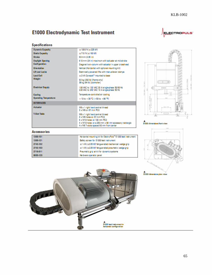
KLB-1002
65
KLB-1002
66
Appendix B – Materials
Materials:
1. Sample Fixation
Epoxy
1.5in Unthreaded PVC Cap
¼-20 2.5in Eyehook and Nut
¼-20 1.5in Wood Screw
Polyurethane Sawbone
Human Cadaveric Sternum
Plate and Extensometer Grip (Custom manufactured at WPI)
70% Ethanol Solution
Gallon Sized Ziplock Bags
2. Screw and Plate
KLS Martin Mandibular 9mm screw
KLS Martin Mandibular Plate
Cap and Plate Anti-wobble system (Created by John Dieselman)
3. Instron
Instron Electropuls E-1000
50N Load Cell
Extensometer
Standard Instron Grip
Instron Console Program
Instron WaveMatrix Program
4. Tools/Instruments
Philips head screw driver
KLS Martin precision screw driver
Power Drill with 1.9mm drill bit
Personal Protection Equipment (PPE)
o Latex Gloves
o Long-sleeve Lab Coat
o Safety Goggles

KLB-1002
67
Appendix C – Steps for Human Sternum Testing
Step 1: Samples were sectioned as shown in the
image to the right by Dr. Ignotz at UMass
Medical School. Samples are stored in -40°C
freezer and thawed in a 4°C refrigerator the night
before testing. Make sure to wear PPE while
handling human tissue.
Step 2: Two holes are drilled into the sternum
segments as shown. The sternum is kept in the
ziplock bag to contain any biohazardous
material. Another hole is drilled into the side of
the rib segment for the anchoring screw.
Step 3: The bone plate is inserted between the
aluminum plates of the custom grip and the
machine screws are tightened. The bone plate is
screwed into the sternum sample as shown in the
image to the right. A wood screw is screwed into
the predrilled hole in the side of the rib to help
anchor the sample in the epoxy.

KLB-1002
68
Step 4: The custom grip is attached to the upper
Instron grip and an endcap with epoxy is filled
and attached to the lower Instron grip. The Instron
grip is then lowered into the epoxy to make sure
the sample is aligned.
Step 5: The epoxy is spread to make sure the
anchoring screw is submerged and the backside of
the sternum is also covered. This prevents
movement at the joint between the rib and the
sternum.
Step 6: The extensometer is screwed into the
custom grip while the epoxy dries for ~25mins.
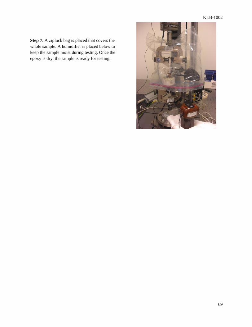
KLB-1002
69
Step 7: A ziplock bag is placed that covers the
whole sample. A humidifier is placed below to
keep the sample moist during testing. Once the
epoxy is dry, the sample is ready for testing.

KLB-1002
70
Appendix D – Matlab Code - Plotting Comparison Graphs Using Fit
Curve
This code below will plot the data using a fit curve for each to approximate the average displacement seen
at each point by removing outliers from the data. Outliers are defined as data points that are greater than
1.5 standard deviations from the estimated data fit curve.
close; clear; clc;
ldata1=xlsread('L4 Screw 1.csv');
time1=ldata1(:,1);
cycles1=ldata1(:,3);
extstrain1=ldata1(:,10);
ldp1=ldata1(:,7);
f1=fittype('rat33');
fit1=fit(cycles1,extstrain1,f1);
fdata1=feval(fit1,cycles1);
I1=abs(fdata1-extstrain1)>1.5*std(extstrain1);
outliers1=excludedata(cycles1,extstrain1,'indices',I1);
ldata2=xlsread('L4 Screw 2.csv');
time2=ldata2(:,1);
cycles2=ldata2(:,3);
extstrain2=ldata2(:,10);
ldp2=ldata2(:,7);
fit2=fit(cycles2,extstrain2,f1);
fdata2=feval(fit2,cycles2);
I2=abs(fdata2-extstrain2)>1.5*std(extstrain2);
outliers2=excludedata(cycles2,extstrain2,'indices',I2);
ldata3=xlsread('R2 Screw 1.csv');
time3=ldata3(:,1);
cycles3=ldata3(:,3);
extstrain3=ldata3(:,10);
ldp3=ldata3(:,7);
fit3=fit(cycles3,extstrain3,f1);
fdata3=feval(fit3,cycles3);
I3=abs(fdata3-extstrain3)>1.5*std(extstrain3);
outliers3=excludedata(cycles3,extstrain3,'indices',I3);
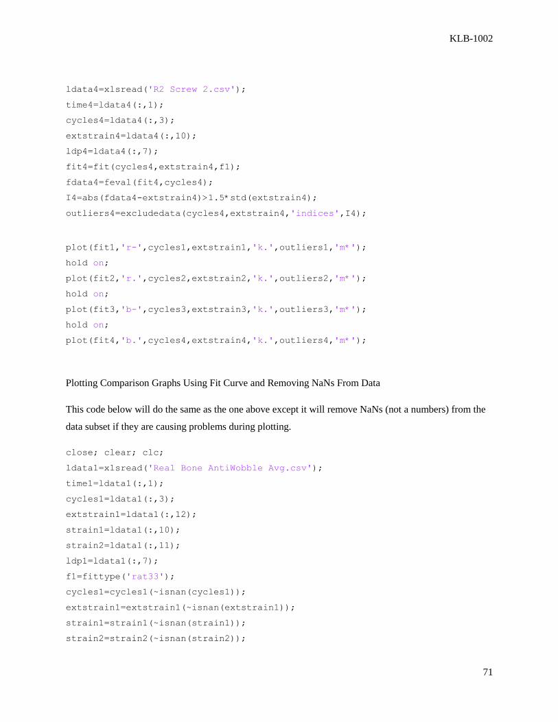
KLB-1002
71
ldata4=xlsread('R2 Screw 2.csv');
time4=ldata4(:,1);
cycles4=ldata4(:,3);
extstrain4=ldata4(:,10);
ldp4=ldata4(:,7);
fit4=fit(cycles4,extstrain4,f1);
fdata4=feval(fit4,cycles4);
I4=abs(fdata4-extstrain4)>1.5*std(extstrain4);
outliers4=excludedata(cycles4,extstrain4,'indices',I4);
plot(fit1,'r-',cycles1,extstrain1,'k.',outliers1,'m*');
hold on;
plot(fit2,'r.',cycles2,extstrain2,'k.',outliers2,'m*');
hold on;
plot(fit3,'b-',cycles3,extstrain3,'k.',outliers3,'m*');
hold on;
plot(fit4,'b.',cycles4,extstrain4,'k.',outliers4,'m*');
Plotting Comparison Graphs Using Fit Curve and Removing NaNs From Data
This code below will do the same as the one above except it will remove NaNs (not a numbers) from the
data subset if they are causing problems during plotting.
close; clear; clc;
ldata1=xlsread('Real Bone AntiWobble Avg.csv');
time1=ldata1(:,1);
cycles1=ldata1(:,3);
extstrain1=ldata1(:,12);
strain1=ldata1(:,10);
strain2=ldata1(:,11);
ldp1=ldata1(:,7);
f1=fittype('rat33');
cycles1=cycles1(~isnan(cycles1));
extstrain1=extstrain1(~isnan(extstrain1));
strain1=strain1(~isnan(strain1));
strain2=strain2(~isnan(strain2));
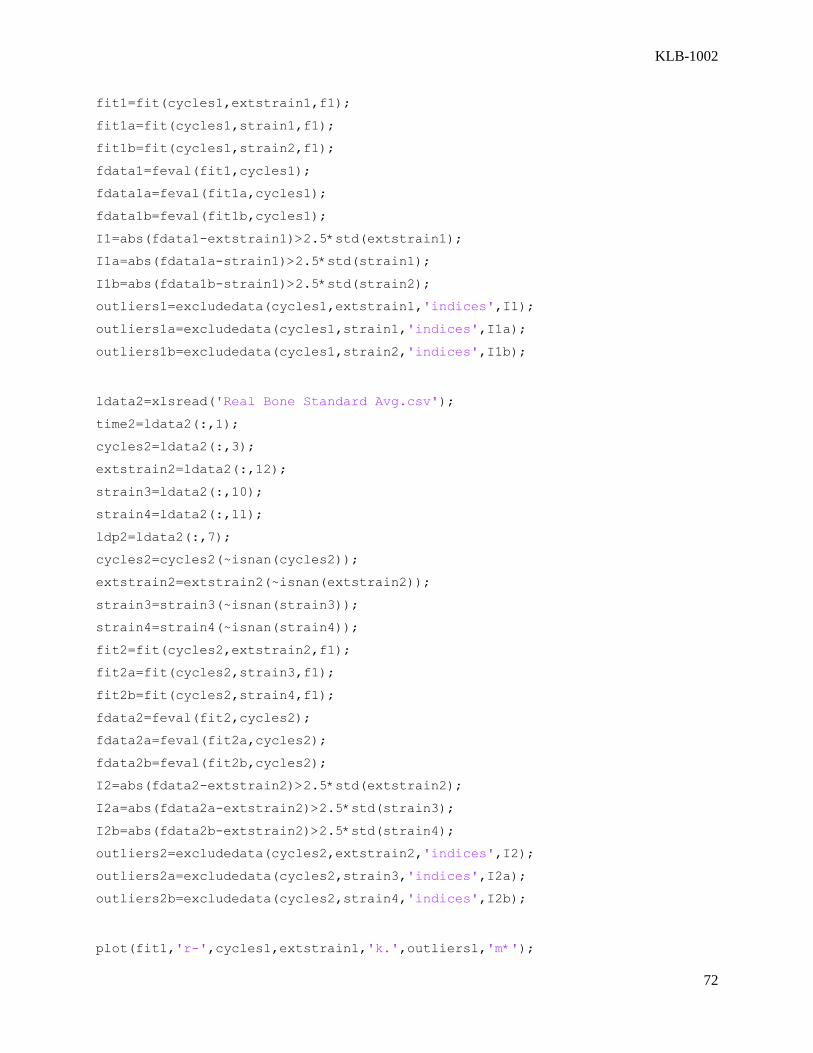
KLB-1002
72
fit1=fit(cycles1,extstrain1,f1);
fit1a=fit(cycles1,strain1,f1);
fit1b=fit(cycles1,strain2,f1);
fdata1=feval(fit1,cycles1);
fdata1a=feval(fit1a,cycles1);
fdata1b=feval(fit1b,cycles1);
I1=abs(fdata1-extstrain1)>2.5*std(extstrain1);
I1a=abs(fdata1a-strain1)>2.5*std(strain1);
I1b=abs(fdata1b-strain1)>2.5*std(strain2);
outliers1=excludedata(cycles1,extstrain1,'indices',I1);
outliers1a=excludedata(cycles1,strain1,'indices',I1a);
outliers1b=excludedata(cycles1,strain2,'indices',I1b);
ldata2=xlsread('Real Bone Standard Avg.csv');
time2=ldata2(:,1);
cycles2=ldata2(:,3);
extstrain2=ldata2(:,12);
strain3=ldata2(:,10);
strain4=ldata2(:,11);
ldp2=ldata2(:,7);
cycles2=cycles2(~isnan(cycles2));
extstrain2=extstrain2(~isnan(extstrain2));
strain3=strain3(~isnan(strain3));
strain4=strain4(~isnan(strain4));
fit2=fit(cycles2,extstrain2,f1);
fit2a=fit(cycles2,strain3,f1);
fit2b=fit(cycles2,strain4,f1);
fdata2=feval(fit2,cycles2);
fdata2a=feval(fit2a,cycles2);
fdata2b=feval(fit2b,cycles2);
I2=abs(fdata2-extstrain2)>2.5*std(extstrain2);
I2a=abs(fdata2a-extstrain2)>2.5*std(strain3);
I2b=abs(fdata2b-extstrain2)>2.5*std(strain4);
outliers2=excludedata(cycles2,extstrain2,'indices',I2);
outliers2a=excludedata(cycles2,strain3,'indices',I2a);
outliers2b=excludedata(cycles2,strain4,'indices',I2b);
plot(fit1,'r-',cycles1,extstrain1,'k.',outliers1,'m*');
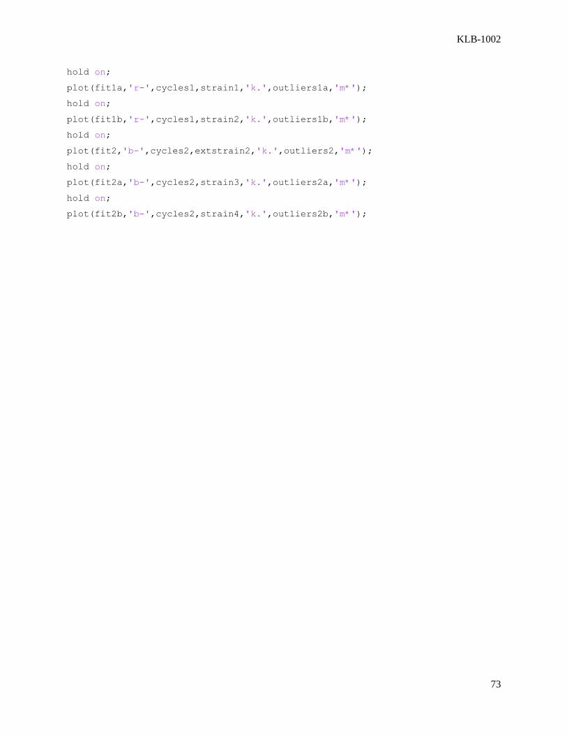
KLB-1002
73
hold on;
plot(fit1a,'r-',cycles1,strain1,'k.',outliers1a,'m*');
hold on;
plot(fit1b,'r-',cycles1,strain2,'k.',outliers1b,'m*');
hold on;
plot(fit2,'b-',cycles2,extstrain2,'k.',outliers2,'m*');
hold on;
plot(fit2a,'b-',cycles2,strain3,'k.',outliers2a,'m*');
hold on;
plot(fit2b,'b-',cycles2,strain4,'k.',outliers2b,'m*');

KLB-1002
74
Appendix E – Testing Results Sawbone Testing:
R1 Screw 1 standard- Screw pulled out after <1000 cycles, was screwed in too close to edge
R1 Screw 2 standard- Failure after 7000 cycles
L4 Screw 1 Antiwobble- 0.23mm displacement at finish
L4 Screw 2 Antiwobble- 0.15mm displacement at finish
R2 Screw 1 standard- 0.47mm displacement at finish
R2 Screw 2 standard- 0.57mm displacement at finish
Note- sample pairing is not required on sawbone as all pieces are of fairly uniform size and density
Real Sterna:
L2 Screw 1 antiwobble- 0.96mm displacement at finish
R1 Screw 1 antiwobble- 0.57mm displacement at finish
R1 Screw 2 antiwobble- 7.16mm displacement at finish, during screw installation, stripped bone
L1 Screw 1 antiwobble- 50N force, sample failed on cycle 68, force too high for osteoporotic bone
L1 Screw 2 standard bicor- .60mm displacement at finish, screw pierced second cortical shell, data not
usable
L1 screw 3 antiwobble- sample failed at cycle 1009, can’t use sterna piece for more than 2 tests
L2 screw 1 antiwobble- sample failed at cycle 1, load cell tripped, improperly set up
R4 screw 1 antiwobble- sample failed at cycle 1010, screwed too close to edge, improperly set up
L2 screw 2 standard- 1.74mm displacement at finish
R4 screw 2 standard- 1.84mm displacement at finish
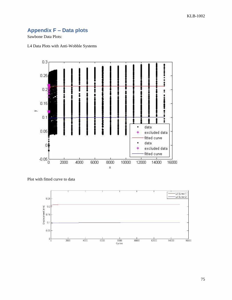
KLB-1002
75
Appendix F – Data plots Sawbone Data Plots:
L4 Data Plots with Anti-Wobble Systems
Plot with fitted curve to data

KLB-1002
76
R2 Data Plots with Standard System
Plot with curve fitted to data
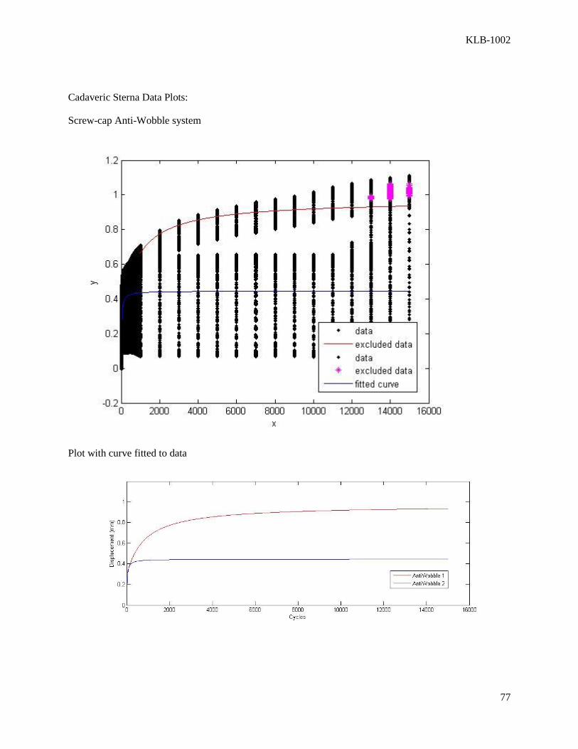
KLB-1002
77
Cadaveric Sterna Data Plots:
Screw-cap Anti-Wobble system
Plot with curve fitted to data
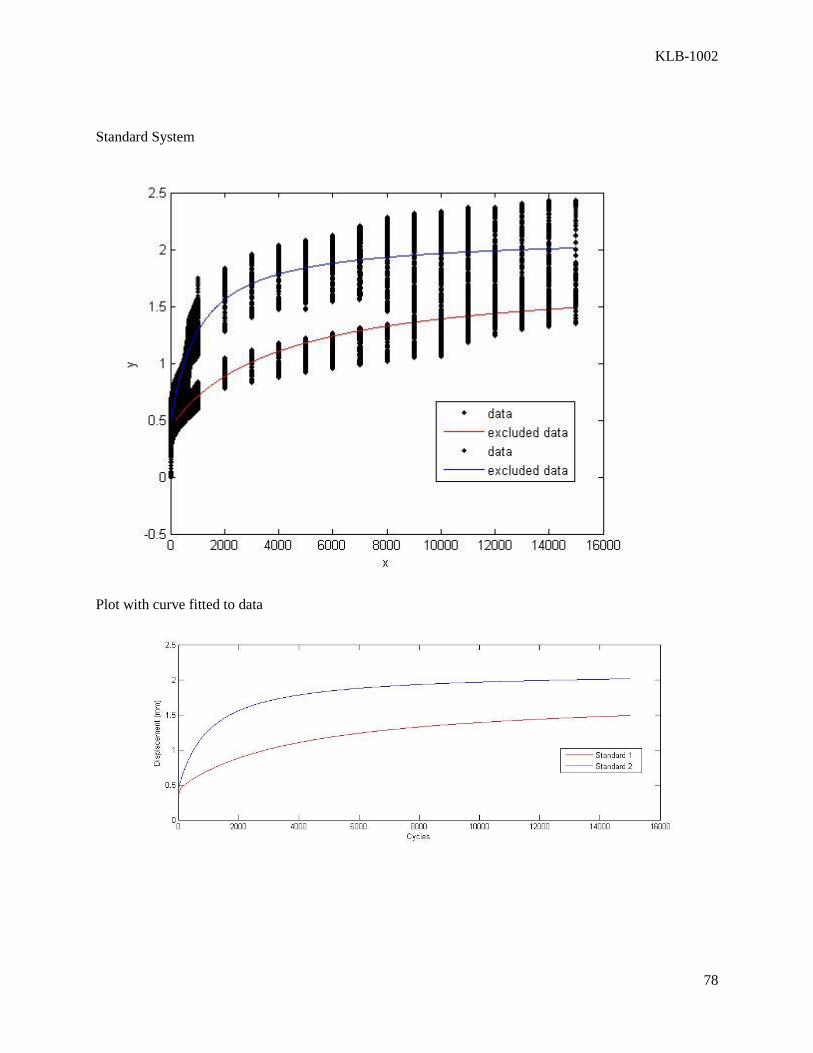
KLB-1002
78
Standard System
Plot with curve fitted to data