DESIGN OF A PILOT PLANT FOR VACUUM INFUSION OF … · OMB NO 0704-OfM 1* «PORT SECURITY ... Vt\e...
86
•goSTAlNABRffy" TECHNICAL REPORT NATICK/TR-88/075 G. 3< DESIGN OF A PILOT PLANT FOR VACUUM INFUSION OF HIGH LIPOIDAL LIQUIDS INTO DRIED FOODS BY GEORGE R. SYDNOR ENGINEERING INCORPORATED, HAMPTON BEACH, VA 23664 JULY 1988 FINAL REPORT JULY 1984 TO JULY 1985 TECHNICAL I NAT; APPROVED FOR PUBLIC RELEASE; DISTRIBUTION UNLIMITED Prepared for UNITED STATES ARMY NATICK RESEARCH, DEVELOPMENT AND ENGINEERING CENTER NATICK, MASSACHUSETTS 01760-5000 FOOD ENGINEERING DIRECTORATE
-
Upload
truongtram -
Category
Documents
-
view
213 -
download
0
Transcript of DESIGN OF A PILOT PLANT FOR VACUUM INFUSION OF … · OMB NO 0704-OfM 1* «PORT SECURITY ... Vt\e...
•goSTAlNABRffy"
TECHNICAL REPORT NATICK/TR-88/075
G. 3<
DESIGN OF A PILOT PLANT FOR VACUUM INFUSION OF
HIGH LIPOIDAL LIQUIDS INTO DRIED FOODS
BY
GEORGE R. SYDNOR ENGINEERING INCORPORATED, HAMPTON BEACH, VA 23664
JULY 1988
FINAL REPORT JULY 1984 TO JULY 1985
TECHNICAL I
NAT;
APPROVED FOR PUBLIC RELEASE; DISTRIBUTION UNLIMITED
Prepared for
UNITED STATES ARMY NATICK RESEARCH, DEVELOPMENT AND ENGINEERING CENTER
NATICK, MASSACHUSETTS 01760-5000
FOOD ENGINEERING DIRECTORATE
DISCLAIMERS
The findings contained in this report are not to
be construed as, an official Department of the Army
position unless so designated by other authorized
documents.
Citation of trade names in this report does not
constitute an official endorsement or approval of
the use of such items.
DESTRUCTION NOTICE
For Classified Documents:
Follow the procedures in DoD 5 2 00.22-M , Industrial
Security Manual, Section 11-19 or DoD 5200.1-R,
Information Security Program Regulation, Chapter IX
For Unclassified/Limited Distribution Documents:
Destroy by any method that prevents disclosure of
contents or reconstruction of the document.
UNCLASSIFIED SECURITY CLASSIFICATION OF TWS PAGE AMaooste
REPORT DOCUMENTATION PAGE form Approved OMB NO 0704-OfM
1* «PORT SECURITY CtASS.f'CATlON
Unclassified 10 RESTRICTIVE MARKINGS
2*. SECURITY CLASSIFICATION AUTHORITY
20. DECLASSIFICATION/DOWNGRADING SCHEDULE
3 DISTRIBUTION/AVAILABILITY OF REPORT
Approved for public release, distribution unlimited.
4 PERFORMING ORGANIZATION REPORT NUMBER(S) 5 MONiTOR'NG ORGANIZATION REPORT NUM8ER(S)
NATICK/HR-88/07 5
6«. NAME Of PERFORMING ORGANIZATION
Engineering Incorporated
6c. ADDRESS (Oty, State, and ZIP Cod*)
Hampton Beach, VA 23664
60 OFFICE SYMBOL (H applicable)
7». NAME OF MONITORING ORGANIZATION
U.S. Army Natick RD&E Center
70 ADDRESS (Cry. State. *nd ZIP Code) ATTN: STRTC-WAA Natick, MA 01760-5018
Ba NAME OF FUNDING/SPONSORING ORGANIZATION
80 OFFICE SYMBOL (If applicable)
9 PROCUREMENT INSTRUMENT IDENTIFICATION NUMBER
DAAK60-85-C-0008 8t ADDRESS (dry. State, and ZIP Coöt) 10 SCLOCt Cf Fu.\DNG NUMBERS
PROGRAM ELEMENT NO
612724
PROJECT NO. 1L16242
4AH99
•ASK
B3
WORK UNIT ACCESSION NO
n TITLE (include Security Classification) Design of a Pilot Plant for Vacuum Infusion of High Lipoidal Liquids into Dried Foods
12 PERSONAL AUTHOR(S) George H. Sydnor
13» TYPE OF REPORT FINAL
30 TIME COVERED FROM Jul 84 TOJUI 85
14 DATE OF REPORT (Year. Month, Day) 1988 July
IS PAGE COUNT
90 16. SUPPLEMENTARY NOTATION
17 COSATi CODES
FIELD GROUP SUB-GROUP
18 SUBJECT TERMS {Continue on reverse if necessary and identify ty block number) fclTCHEN EQUIPMENT AND SUPPLIES, FOOD TRAY(S). DEHYDRATED FOODS , MILITARY RATIONS, VACUUM CHAMBERS
I
> EXPERIMENTAL DESIGN, (over)
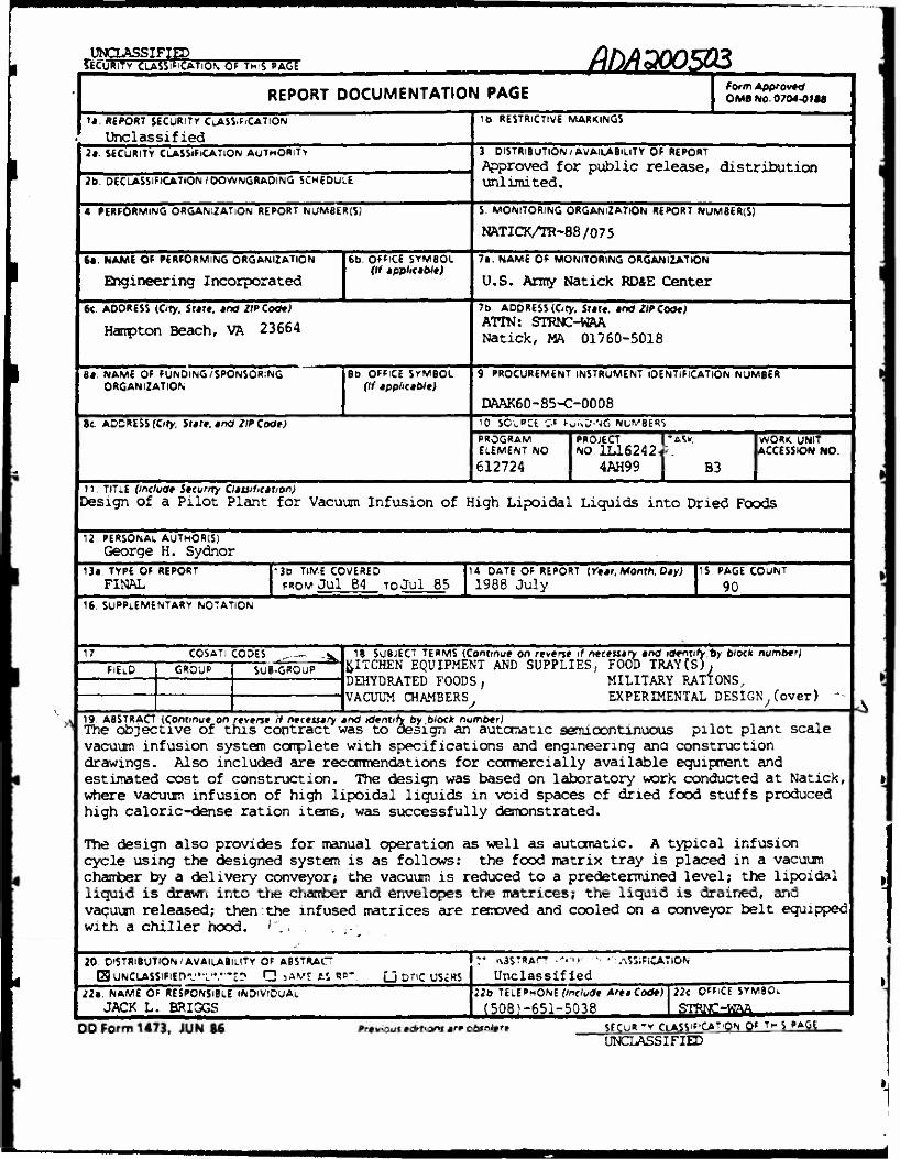
19 ABSTRACT {Continue on reverse if necessary and identify by block number) The objective of this contract was to design an automatic semicontinuous pilot plant scale vacuum infusion system complete with specifications and engineering ana construction drawings. Also included are recommendations for commercially available equipment and estimated cost of construction. The design was based on laboratory work conducted at Natick, where vacuum infusion of high lipoidal liquids in void spaces of dried food stuffs produced high caloric-dense ration items, was successfully demonstrated.
The design also provides for manual operation as well as automatic. A typical infusion cycle using the designed system is as follows: the food matrix tray is placed in a vacuum chamber by a delivery conveyor; the vacuum is reduced to a predetermined level; the lipoidal liquid is drawn into the chamber and envelopes the matrices; the liquid is drained, and vacuum released; then the infused matrices are removed and cooled on a conveyor belt equipped with a chiller hood. /".
20 DISTRIBUTION'AVAILABILITY OF ABSTRACT SUNCLASSlFlEn'VL'V'S:» Q jwj AS RB" U DtiC US£RS
22: NAME OF RESPONSIBLE INDIVIOUAL
JACK L. BRIGGS
«\3STRAfT -'•■ii'
Unclassified ASSiFlCATlON
220 TELEPHONE (Include Area Code)
(508)-651-5038 22c OFFICE SYMBOi
STRMT-WAA
DO Form 1473, JUN 86 Previous editions are obsolete SECUR -* CLASSIFICATION QF TH S PAGE
UNCLASSIFIED
Box 18 (Cön'd)
^INFÜSICNS
LIQUIDS,
PILOT PLANTS
FOOD PROCESSDC , (6tU) ) r* -
PREFACE
This research on design of a pilot plant for vacuum infusion of high
lipoidal liquids into dried foods was performed by Engineering Incorporated,
Hampton, VA, under U.S. Army Natick RD&E Center contract DAAK60-85-C-0008
during the period July 1984 to July 1985.
Vt\e Natick Project Officer was Mr. Jack L. Briggs.
Gore-Tex is a registered trade name. Tne citation or trade names
and listing of suggested manufacturers in this report does not constitute
an official endorsement or approval of ^he use of such items.
ACKNOWLEDGEMENTS
We thank Mr. John Ayoub for his Engineering support to the project
and Mrs. Brigetta Whalen for her Secretarial assistance; both from
U.S. Army Natick RD&E Center (Natick).
111
Accession For S
NTIS GRAJtl DTIC TAB Unarm oun«e<? Justl f lentlor1
n
Bv
Di :.t: ibuticr/
AvaliaMllty Cedes kAvpil aijJ/ur
Dist 1'pooial
\
X
^^m
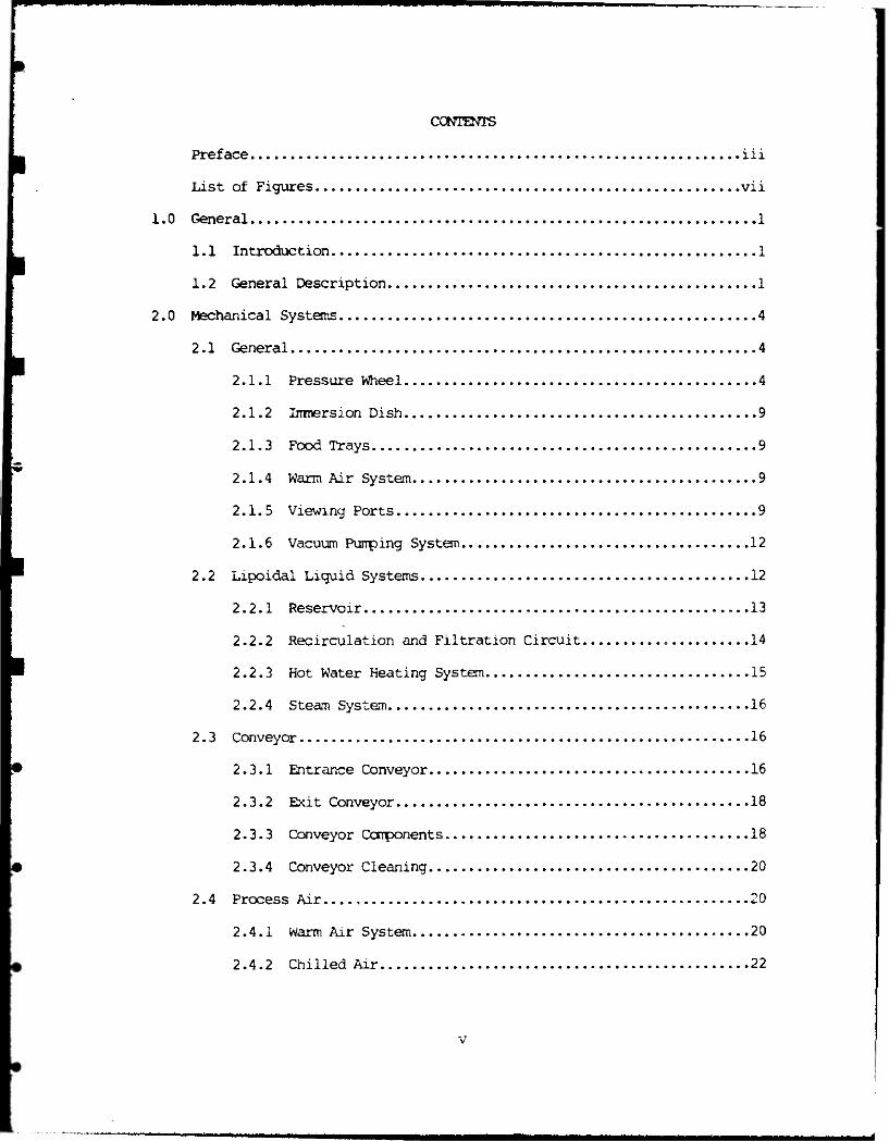
CONTENTS
Preface iii
List of Figures vii
1.0 General 1
1.1 Introduction 1
1.2 General Description 1
2.0 Mechanical Systems 4
2.1 General 4
2.1.1 Pressure Wheel 4
2.1.2 Immersion Dish 9
2.1.3 Food Trays 9
2.1.4 Warm Air System 9
2.1.5 Viewing Ports 9
2.1.6 Vacuum Pumping System 12
2.2 Lipoidal Liquid Systems 12
2.2.1 Reservoir 13
2.2.2 Recirculation and Filtration Circuit 14
2.2.3 Hot Water Heating System 15
2.2.4 Steam System 16
2.3 Conveyor 16
2.3.1 Entrance Conveyor 16
2.3.2 Exit Conveyor 18
2.3.3 Conveyor Components 18
2.3.4 Conveyor Cleaning 20
2.4 Process Air 20
2.4.1 Warm Air System 20
2.4.2 Chilled Air 22
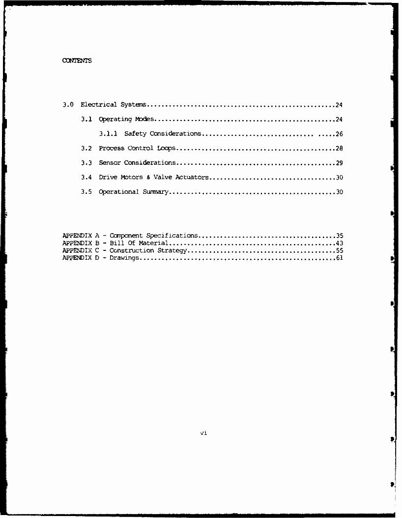
CONTENTS
3.0 Electrical Systems 24
3.1 Operating Modes 24
3.1.1 Safety Considerations 26
3.2 Process Control Loops 28
3.3 Sensor Considerations 29
3.4 Drive Motors & Valve Actuators 30
3.5 Operational Summary 30
APPENDIX A - Component Specifications 35 APPENDIX B - Bill Of Material 43 APPENDIX C - Construction Strategy 55 APPENDIX D - Drawings 61
VI
MM

LIST OF FIGURES
Figure No. Title
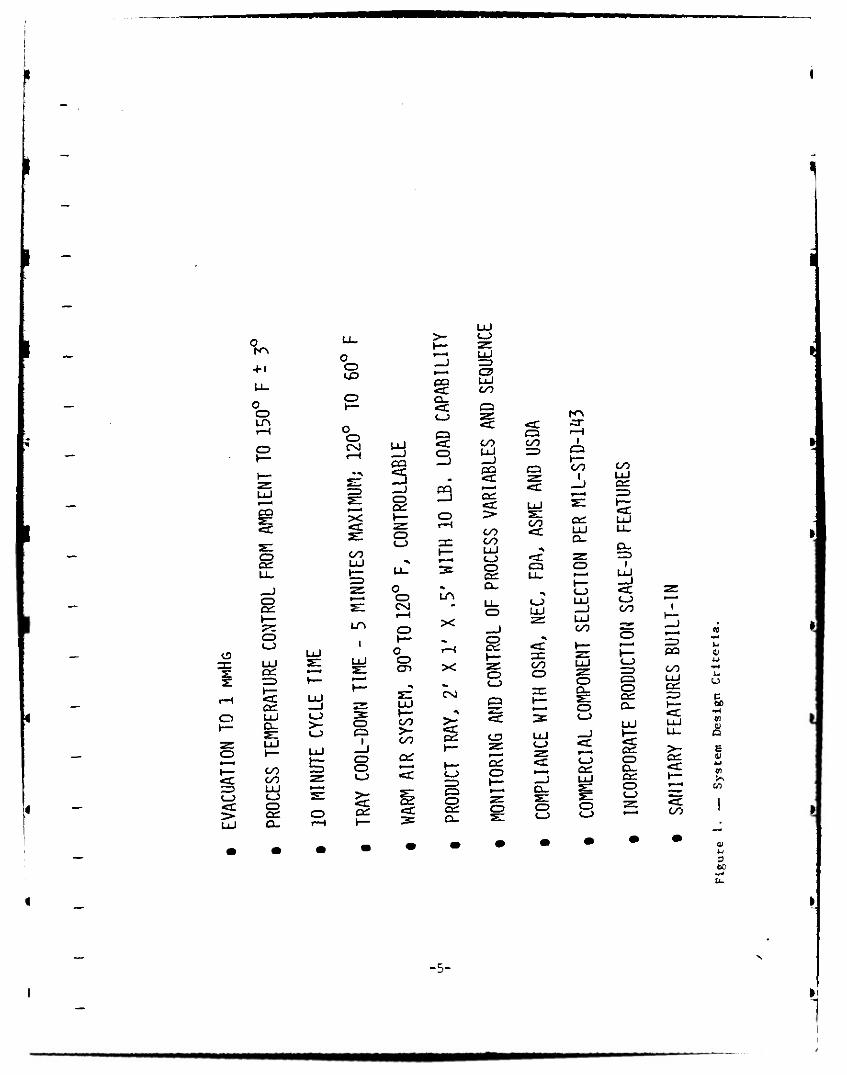
1 System Design Criteria
■ 2 System Interfaces r 3 Elevated Equipment Arrangement
4 Vacuum Chamber - Site Elevation
L 5 Food Tray
6 Mechanical System Diagram
7 Delxvery/Extraction Conveyor
8 Conveyor Drive Detail
* 9 Conveyor Belt Detail
10 Operator Console Assembly
11 Operator Panel
Page
5
6
7
8
10
11
17
19
21
25
11
Vll
p
I
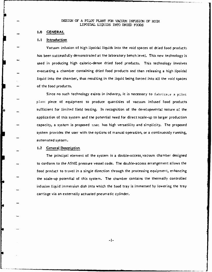
DESIGN OF A PILOT PLANT FOR VACUUM INFUSION OF HIGH LIPOIDAL LIQUIDS INTO DRIED FOODS
1.0 GENERAL
1.1 Introduction
Vacuum infusion of high Jipoidal liquids into the void spaces of dried food products
has been successiuUy demonstrated at the laboratory bench level. This new technology is
used in producing high caloric-dense dried food products. This technology involves
evacuating a chamber containing dried food products and then releasing a high lipoidal
liquid into the chamber, thus resulting in the liquid being forced into all the void spaces
of the food products.
Since no such technology exists in industry, it is necessary to fabricate a pilot
plant piece of equipment to produce quantities of vacuum infused food products
sufficient for limited field testing. In recognition of the developmental nature of the
application of this system and the potential need for direct scale-up to larger production
capacity, a system is proposed tinat has high versatility and simplicity. The proposed
system provides the user with the options of manual operation, or a continuously running,
automated system.
1.2 General Description
The principal element of the system is a double-access, vacuum chamber designed
to conform to the A5ME pressure vessel code. The double-access arrangement allows the
food product to travel in a single direction through the processing equipment, enhancing
the scale-up potential of this system. The chamber contains the thermally controlled
infusion liquid immersion dish into which the food tray is immersed by lowering the tray
carriage via an externally actuated pneumatic cylinder.
-1-
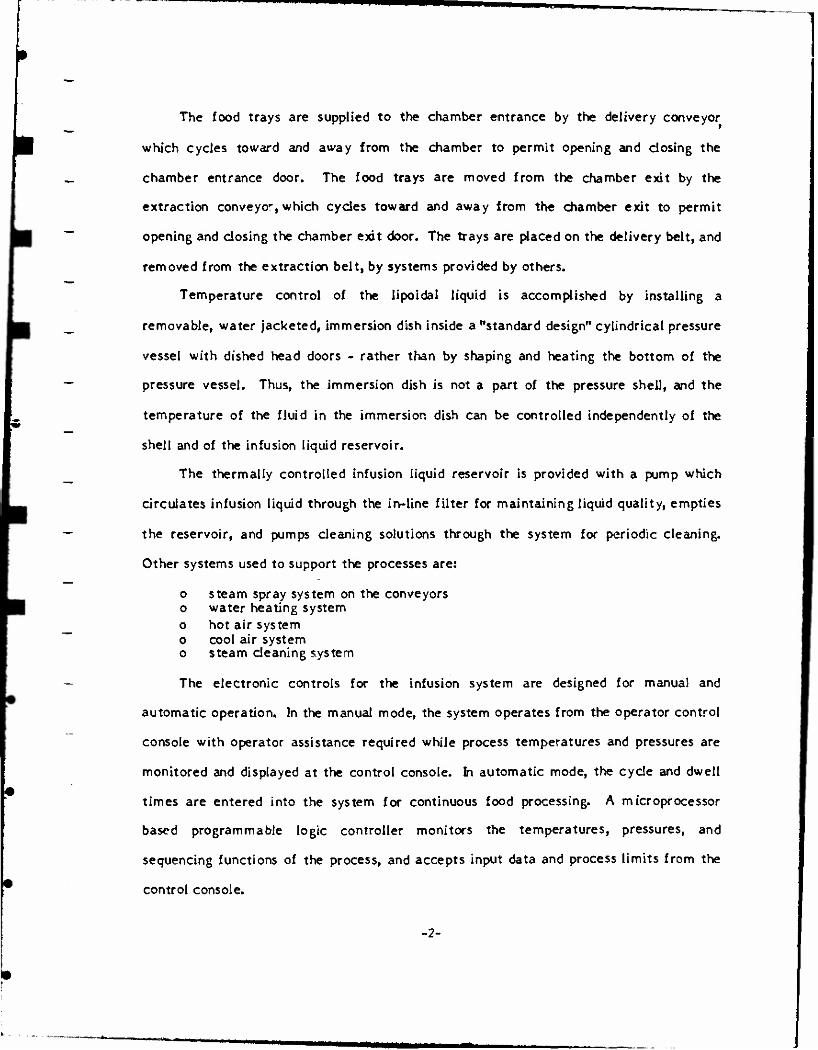
The food trays are supplied to the chamber entrance by the delivery conveyor
which cycles toward and away from the chamber to permit opening and closing the
chamber entrance door. The food trays are moved from the chamber exit by the
extraction conveyor, which cycles toward and away from the chamber exit to permit
opening and closing the chamber exit door. The trays are placed on the delivery belt, and
removed from the extraction belt, by systems provided by others.
Temperature control of the lipoidal liquid is accomplished by installing a
removable, water jacketed, immersion dish inside a "standard design" cylindrical pressure
vessel with dished head doors - rather than by shaping and heating the bottom of the
pressure vessel. Thus, the immersion dish is not a part of the pressure shell, and the
temperature of the fluid in the immersion dish can be controlled independently of the
shell and of the infusion liquid reservoir.
The thermally controlled infusion liquid reservoir is provided with a pump which
circulates infusion liquid through the in-line filter for maintaining liquid quality, empties
the reservoir, and pumps cleaning solutions through the system for periodic cleaning.
Other systems used to support the processes are:
o steam spray system on the conveyors o water heating system o hot air system o cool air system o steam cleaning system
The electronic controls for the infusion system are designed for manual and
automatic operation. In the manual mode, the system operates from the operator control
console with operator assistance required while process temperatures and pressures are
monitored and displayed at the control console. In automatic mode, the cycle and dwell
times are entered into the system for continuous food processing. A microprocessor
based programmable logic controller monitors the temperatures, pressures, and
sequencing functions of the process, and accepts input data and process limits from the
control console.
-2-
The interlock, safeguarding, and operational steps are implemented through the
programmable logic controller. Emergency stops and manual overrides for automatic
equipment are designed in to assure overall plant safety. Details of each system are
provided in the following sections.
-3-
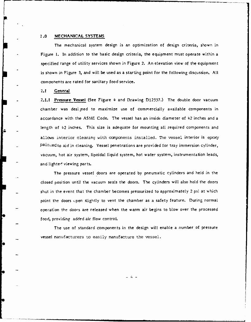
2.0 MECHANICAL SYSTEMS
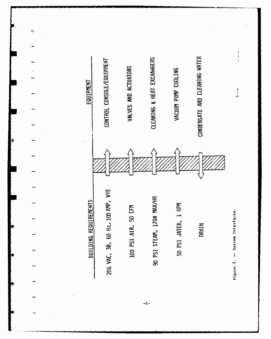
The mechanical system design is an optimization of design criteria, shown in
Figure I. In addition to the basic design criteria, the equipment must operate within a
specified range of utility services shown in Figure 2. An elevation view of the equipment
is shown in Figure 3, and will be used as a starting point for the following discussion. All
components are rated for sanitary food service.
2.1 General
2.1.1 Pressure Vessel (See Figure k and Drawing D12557.) The double door vacuum
chamber was designed to maximize use of commercially available components in
accordance with the A5ME Code. The vessel has an inside diameter of kl inches and a
length of U2 inches. This size is adequate for mounting all required components and
allows interior cleaning with components installed. The vessel interior is epoxy
paincedto aid in cleaning. Vessel penetrations are provided for tray immersion cylinder,
vacuum, hot air system, lipoidal liquid system, hot water system, instrumentation leads,
and lighted viewing parts.
The pressure vessel doors are operated by pneumatic cylinders and held in the
closed position until the vacuum seals the doors. The cylinders will also hold the doors
shut in the event that the chamber becomes pressurized to approximately 2 psi at which
point the doors upen slightly to vent the chamber as a safety feature. During normal
operation the doors are released when the warm air begins to blow over the processed
food, providing added air flow control.
The use of standard components in the design will enable a number of pressure
vessel manufacturers x,o easily manufacture the vessel.
- A -
I
>
+1
o o LA
O o LO
O CD C-0
o 3:
CD
UJ
1 s CD OS
CD CD
as UJ
UJ
00 00 UJ c_> CD OS O-
X
CO
Ln
1
UJ I
>- CD
UJ
CD Q
I -J CD CD CD
S
-J
s o CD
o CD CNJ
O CD en
CO
CO
as
as
a_
CD
3 CD
LA
X
H
X
CNJ
5 as
CD 3> pa CD as
c_? 2: UJ Z=) CD UJ CO
CO
as
CO CO UJ c-> CD as
O
S o
es
as o
CO
CD
•5c UJ
CO
•a: (=1
CD UJ
CO CD
CD
—»
o
I
V— CO
I
UJ CL.
o
1— CJ>
UJ CO
CD a_ CD
CJ> as
CD
CO UJ as
Q- rD
1
C_> CO
(31 o as a.
cm CD a_ CD
pa
co LU as
>- as
CO
TO —J
u
O
c 60
"H
E QJ *-> tr
a;
o 00
»J
-5-
21 UJ
CO err UJ
al £ CO 3E CD
CD <C 3E
h-
1 =3 O UJ
|
C3 X UJ
_J O O O
a. 0 «X D> co Q UJ s:
=5 2: O 5 — a.
UJ <-> CO
OÖ s: 0 £ CD HD
Cf —J ^»■« 0
2: > § > 0 CJ c~>
UJ
<c
CD
C_>
2:
CO
o C->
CO
OS
o UJ atz
CD 2: •—* _j
CQ
8 i-H
s Si
c_>
CO o
3E=
CJ
0
5c
CO a. o CD
s
UJ \— CO
CO
o en
Q- CD
CO
o
e 0)
in
0)
3
-6-

u I I
LZ P,
o
C3
4-J c
c
I
(1)
5 r-l w
fc.
-7-

_J oo •—«
LU nr Q _J oo C=J >■ =3 2^ <c <c _J O en CXl Ll_ L_> H- **>. CO
CÜ >- Q <c LU <c O LU en O —1 y h— u_ LJ N^
oo OO
ffl
w 4) t> •H C/)
U 01
■a TO
3 U
>
0> k-
3
I
2.1.2 ImriliP ftalt (See Figure 4 and Drawing D12562) . The immersion dish
li a water jacketed optn ktttit inside tht pressure vessel and If used to
contain tht lipoidal liquid and maintain the liquid at tht rtqulrtd
temperature. Tht dish 1« 30 Inches lnaldt diameter with a maximum dapth of 0
inchai. Tht liquid temperature it control lad by varying tht flow of hot wator
through tht ktttit Jacktt.
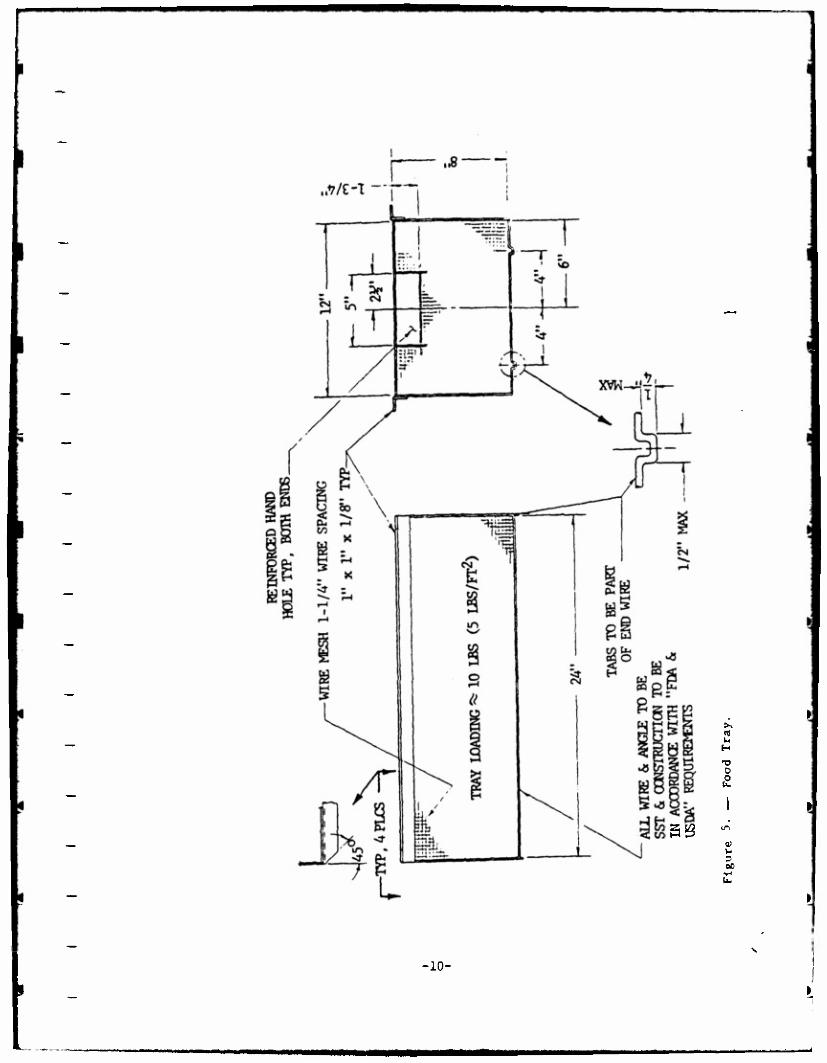
2.1.3 Food Tray« (St« Figure 5 and Drawing D12562). The food tray« are
manufactured from a stainless steel wire me«h product to meet the U.S.
Department of Agriculture (USDA) requirement« for food handling. They are
approximately 24-3/8 lnche« by 12 Inches wide by 8 inches deep and are equipped
with a cover to contain the food product during the immersion process. The
food trays are carried to the vessel by the conveyor where the tray engages the
immersion device. After the Immersion process is complete the next tray pushes
the completed tray onto the exit conveyor.
2.1.4 warm Air System (See Figure 6 and Drawing D12561). After the food
Immersion process is complete, the tray is raised from the llpoidal liquid and
drained by two processes. The first process shakes the food tray causing any
liquid droplets to fall back Into the immersion dish. A warm air system then
blows filtered air over the food product to complete the excess liquid
removal. The air temperature is maintained between 00*F (32*C) and 120*
(40*C) by a steam coll heating system. Air flow over the food is optimised
by a manifold that was designed with a single attachment to the vessel and with
a hinged end plate to allow cleaning without removal.
2.1.5 Yiewlnl Ports (See Drawing D12555). The chamber has two viewing port«
sised to provide ample area for observing the infusion process. Lights are
provided on the vessel exterior of the ports to aid in viewing.
0
I
fcgg
«g u H
0
U o bO
-10-
00
£ cu *-> in
re U
g X u
oc
-11-
2.1.6 Vacuum Pumping System (See Figure 6 and Drawing D12556). The vacuum
pumping system consists of standard components integrated into a custom system
matched to the infusion process. The vacuum system is sized to provide a one minute
pump down time with a dry, clean chamber. Actual run times required to reach a 1 torr
vacuum level will depend on a number of variables including the type of lipoidal liquid in
use, the cleanliness of the vessel (longer pumping time at the end of a shift), vessel
temperature, the type of food being infused, etc. The vacuum pump is protected from
food outgassing products by a refrigerated baffle which prevents food products from
contaminating the vacuum pump lubricating oil. The baffle also traps any pump lubricant
vapors which may try to backstream to the vessel. A vacuum isolation valve is
modulated while the vacuum pump continuously runs to maintain the desired setpoint.
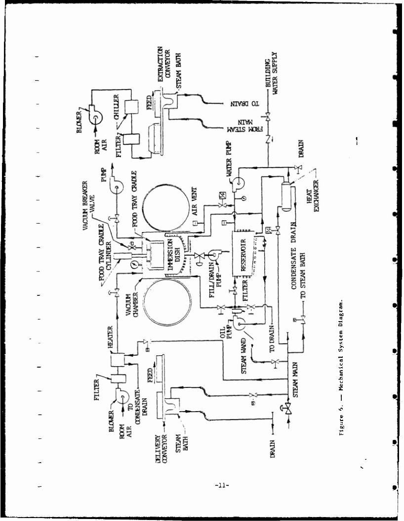
2.2 Lipoidal Liquid Systems; The lipoidal liquid is provided at the proper conditions to
the immersion dish from an external reservoir through a liquid distribution system. The
overall mechanical system diagram is shown in Figure 6. The basic subsystems which
support the infusion process are:
0 reservoir 0 recirculation and filtration circuit 0 hot water heating system 0 steam system
These systems provide lipoidal liquid to the immersion dish at the proper
temperature, filter any suspended food particles from the liquid after the immersion
process, and store liquid that will be needed for each processing run.
-12-
MMm
I 2.2.1 Reservoir (See Drawing D12562). The reservoir is constructed of an embossed
double wall stainless steel shell to provide a hot water jacket which will maintain the
lipoidal liquid at the required temperature. A hinged cover is provided on the reservoir
to maintain cleanliness during use while facilitating filling and clean up operations. The
system may be drained by using the recircuiation pump, after shifting some valve
positions, or by a manual drain. The reservoir is sized to contain all the iipoidai liquid
expected for a 2 hour production run as determined below:
Required Liquid Source
Immersion Dish & Piping
Liquid Consumed in Production
Reserve
Total
Volume (Cubic Feet)
2.60
1.50
.2
tt. 3
Assuming a lipoida! liquid specific gravity of .9, the entire infusion system charge
will then weigh:
W = Volume x SG x Density of Water
= 4.3 x .9 x 62.4 = 242 pounds
The reservoir is capable of holding 300 pounds of lipoidal liquid as a maximum
charge.
The infusion liquid temperature is maintained by circulating hot water through the
reservoir jacket. The hot water is regulated by two automatic temperature controllers
within the hot water circulation subsystem,which is described in detail in Section 2.2.3.
-13-
2.2.2 Eeclroulatlon and Filtration Clroult (See Figure 6 and Drawing
D12550). Since the infusion syetem it a reeearch facility, it if neceesary
that the systems allow ufe of varloui liquide to provide data and ftudy the
■oat efficient methods to aaeortaln the optimum lnfualon liquid into various
products. The viscosity of the liquids at the processing temperature ranges
from 800 to 0000 centlpoise. Thle large range of viscosity precluded using the
vacuum to fill and drain the Immersion dish because sanitary pipe and fittings
were not readily available in sizes necesfary to meet the one minute fill and
drain criteria. Baeed on the analysis of the system and operating
requirements, transfer pumpe were selected to fill and drain the Immersion dish
and recirculate the liquid.
The recirculation pump cycles the infusion liquid out of the reservoir
through a 100 mesh strainer to remove suspended food partlclee from the fluid.
The liquid then ii returned to the reservoir for use in the infusion process.
The recirculation pump runs continuously to agitate the liquid and aid In
maintaining a uniform temperature. The recirculation pump is also used to
drain the lipoldal liquid at the end of a procese run by shifting two manual
valves. After the reservoir has been drained the tank can then be filled with
a cleaning solution, which can be circulated to remove heavy deposits from the
system. A third manual valve allowe the cleaning solution to be pumped into
the Immersion dish for cleaning. The recirculation pump provldee a 5-gallon
per minute (gpm) flow rate and up to 85 pounde per square inch absolute (peia).
The low flow rate for the recirculation pump was required to allow continuous
operation when the fill/drain pump if operating. The pressure capacity of the
pump allowe forcing of the vlecoue fluid through the strainer unit. The
strainer's capacity is twice the pump output pressure, therefore, a single
strainer unit should be sufficient for normal use. Additional unite can be
paralleled easily into the syetem if the need arises.
14
This system is adaptable to liquids with even higher viscosities. The viscosity
limit should be determined by experiment using the actual system since the governing
flow equations begin to lose their accuracy as the Reynolds number for flow drop below
100. The system Reynolds number is approximately 1.
The pumps chosen for transfer and recirculation are of the rotary lobe positive
displacement type. To operate with viscous liquids, the internal clearances between the
parts must be larger to allow the proper pump function. The larger liquid clearances
allow the pump to run dry without damage but also insure that the pump can only
operate with a positive suction head, or with an unbroken fluid column. These pumps are
commonly used in food processing and are used to move liquids up to one million
centipoise in viscosity.
To close off the fill and drain pipe to the immersion dish, a remote actuated food
service poppet valve is used. This valve has a USDA approved rubber seating surface
which is rated for 65 psi differential pressure. This valve is rated "dean-in-place type"
but is easily disassembled for servicing. The piping design for this system incorporates
food service clamped flange connections with O-ring seals. Any section or run of pipe
can be disconnected from the system without a complete disassembly of the entire
system.
2.2.3 Hot Water Heating System (See Figure 6 and Drawing D12555). A hot water
system is used to heat and maintain the temperature of the lipoidai liquid in the reservoir
and the immersion dish. Each vessel has a water jacket, selected to allow uniform heat
input to the liquid. The water entering the system is heated to the required temperature
in a steam/water heat exchanger. The steam rate is automatically controlled to main-
tain the water temperature at the setpoint. Hot water is circulated to the components
by a centrifugal pump.
-15-
The immersion dish can be maintained at a temperature equal to or below the reservoir
by use of a separate temperature controller and a modulating valve in the hot water line.
Vents and drains allow trouble free filling and flushing of the system.
2.2-* Steam System (See Figure 6 and Drawing D12555). The steam system is supplied
from an available 90 psig supply and is used to heat water, heat air, and to clean the
conveyors. The steam rate to the water heat exchanger is automatically controlled to
maintain water temperature. The warm air is heated in a steam-to-air heat exchanger to
maintain the air temperature at 90°F to 120°F by modulating steam flow rate. Steam
supply pressure is reduced at the heat exchanger to five psig for air heating.
The steam system also supplies steam for automatically cleaning the conveyor
systems while they are operating through nozzles enclosed on each conveyor. For
additional cleaning of conveyors and other components, a steam cleaning wand with soap
dispenser/mixer is provided. This system allows components to be soaped and then rinsed
to ensure maximum cleanliness.
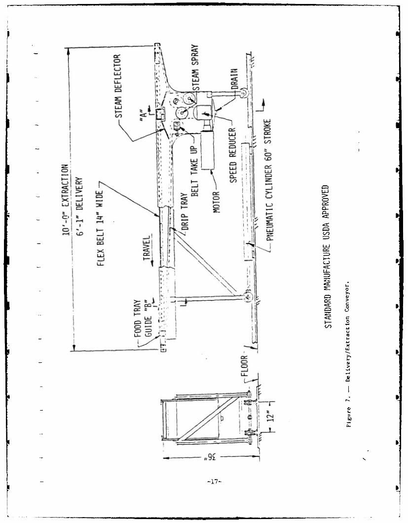
2-3 Conveyors (See Figure 7 and Drawings D12559 & D12560). The entrance and exit
conveyor systems are similar in construction. The exit conveyo*' has a chiller hood and
the last portion of this conveyor consists of a slideway. These differences will be
covered in more detail once the function of each unit is discussed.
2.3.1 Entrance Conveyor; The entrance conveyor is loaded by the system operator with
filled food trays and at the proper time in the system cycle ' the conveyor is driven by a
pneumatic cylinder toward the open vacuum chamber. A limit switch stops the conveyor
motion at a preset position, and starts the belt motion. The belt feeds a loaded food tray
onto the tray cradle. The belt motion stops when the next food tray, loaded on the
conveyor, contacts a tray position limit switch at the front of the conveyor. The
conveyor assembly then retracts and the infusion cycle continues.
-16-
»
5 er:
ex:
CD er: <x
t— oo
o >> > c 0 u c o
(0
*-> K
>
U.
-17-
r
2.3.2 Exit Conveyor; The exit conveyor has a similar function, with differences to be
discussed. The exit conveyor begins it's cycJe by stroking into the open vacuum chamber,
and stopping 2 to 3 inches away from engaging the food tray on the cradle. The entrance
conveyor must first push the immersed tray into engagement with the exit conveyor
belt. This design was used to eliminate the possibility of a tray bridging the two belt
systems (one tray engaged with both belts). Once a tray is engaged with the exit
conveyor belt, the tray continues along the belt until its position under the chiller hood is
detected by a limit switch. The food tray remains under the chiller hood, which blows
20°F air over the food product to bring it from process temperature down to ambient.
On the next cycle the belt pushes the cooled tray ou f the hood and onto a slide rack
which provides a stack up area for the trays to accumulate. The operator mu<t remove
the food tray after each cycle or the second tray will trip a limit switch and stop the unit
before a food tray can be dropped on the floor. The slide rack assembly is identical to
the wire belt support, but has no belt over it. Aside from the chiller hood end the slide
rack, the exit conveyor is the same as the entrance unit, as discussed previously.
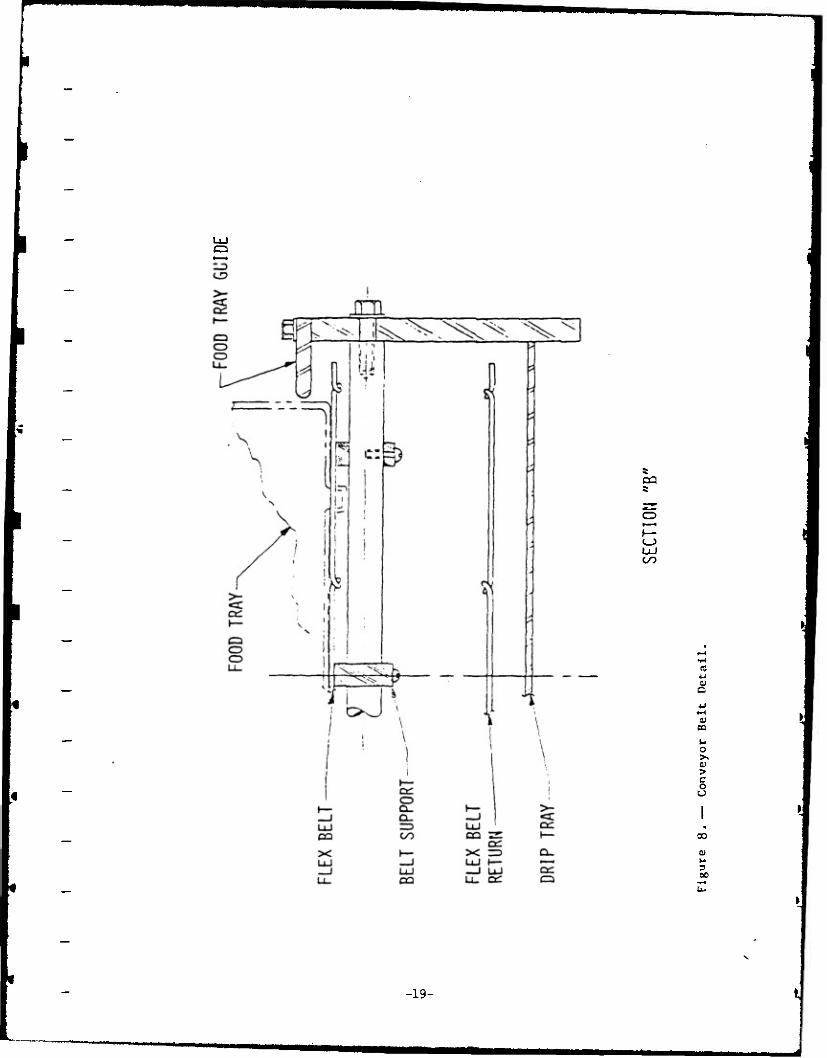
2.3.3 Conveyor Components: A DC variable speed unit was chosen as the conveyor belt
drive to allow the belt speeds to be optimally adjusted. Bearings in this system are
either a high molecular weight polyethylene (HMP) bushings that require no lubrication or
a double sealed ball bearing unit that is lubricated with food safe grease. The flexible
wire belt supports the tray weight by sliding across three HMP belt support rails. To
ensure proper alignment of the food trays for engagement with the vacuum chamber tray
cradle, there are two food tray guides. The guides have a tapered leading edge and then
a straight section to hold the tray steady while it is pushed onto the cradle assembly.
Each food tray has four tabs which engage the wire belt as shown in Figure 6. These tabs
allow the belt to positively push the trays along and limit the angular misalignment that
a tray can have as it engages the tray cradle.
-18-
ca
CO
UJ oo
03 4J
0) cc
u 0 >. >
U
CO
3 00
-19-
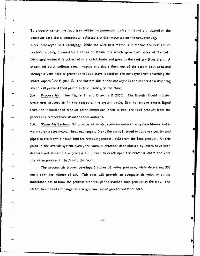
To properly center the food tray within the immersion dish a limit switch, located on the
conveyor base plate, contacts an adjustable striker mounted on the conveyor leg.
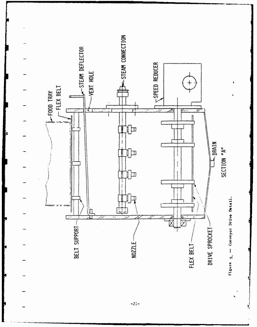
2.3.* Conveyor Beit Cleaning; While the wire belt motor is in motion the belt return
portion is being cleaned by a series of steam jets which spray both sides of the belt.
Dislodged material is collected in a catch basin and goes to the sanitary floor drain. A
steam deflector collects steam vapors and ducts them out of the steam bath area and
through a vent hole to prevent the food trays loaded on the conveyor from absorbing the
water vapors (<fee Figure 9). The bottom side of the conveyor is enclosed with a drip tray
which will prevent food particles from falling on the floor.
2.* Process Air (See Figure 6 and Drawing D12555): The lipoidal liquid infusion
cycle uses process air in two stages of the system cycle, first to remove excess liquid
from the infused food product after immersion, then to cool the food product from the
processing temperature down to room ambient.
2.^.1 Warm Air System; To provide warm air, room air enters the system blower and is
warmed by a steam--to-air heat exchanger. Next the air is filtered to food use quality and
piped to the warm air manifold for removing excess liquid from the food product. At this
point in the overall system cycle, the vacuum chamber door closure cylinders have been
deenergized allowing the process air blower to crack open the chamber doors and vent
the warm process air back into the room.
The process air blower develops 5 inches of water pressure, while delivering 300
cubic feet per minute of air. This rate will provide an adequate air velocity at the
manifold slots to blow the process air through the stacked food product in the tray. The
steam to air heat exchanger is a single row finned galvanized steel core.
-2U-
O
^->
o
CQ o DQ
X
&
> u O
u o
•^. >. C_> 01
O > c o Cd
a. u oo
1
Llj 1 > • ►—< <J\ CÜ a
3 ÖC
-21-
wmmmmmmmm
A thermostatically controlled steam throttling valve is used to control the process air
temperature, with the thermostatic bulb placed just upstream of the filter unit to obtain
a mixed air temperature. The steam supply is reduced by a regulating valve from the 90
psi main to 5 psi for use in the coil. The coil performance can be improved by raising
this regulated steam pressure, if needed. Air temperatures approaching those of the
steam are possible due to the large coil size. The coil size was designed to match the
filter duct size available, which eliminates aduitional transition pieces and makes a
compact unit. The air filter provides 99.9+ percent removal of airborn particulate
matter and is suitable for clean room or sanitary use. The air duct transitions after the
filter down to the 3" pipe size for the vacuum chamber penetration. A 3" butterfly
vacuum valve provides the sealing needed during the vacuum process and minimal
restriction when the process air is required.
2.4.2 Chilled Air; To provide chilled process air room air enters the system blower and
is driven through an evaporator coil. The chilled air is filtered and ducted to the chiller
hood to cool the infused food product from the processing temperature of up to 150° F
down to 60°F. The cool air vents out the hood into the room. For added efficiency a
second flexible duct can be added to the tray inlet side of the chiller hood to recycle the
chilled air. Given the low density food products envisioned for this system, the lower
hood temperatures were not considered necessary at this time.
The evaporator coil receives freon from a packaged refrigeration unit with built-
in controls. A thermostatic bulb mounted in the coil duct will provide the refrigeration &
unit with its temperature feedback. A second set of refrigerant lines supplies the
vacuum trap with coolant (a needle valve in the trap's liquid supply line will control
coolant flow through the trap coil). Identical air filter units will be used in warm and
chilled air supplies to simplify filter replacement. A flexible 6" duct connects the air
transition from the filter to the chiller hood.
-22-

tmmmmmmm
The air handling unit is located over the midpoint of the exit conveyor travel to minimize
hose travel. The chiller hood is designed to split the air flow and ensure cold air Hows
across the top and bottom surfaces of the infused food.
-23-
•
«■■
3.0 ELECTRICAL SYSTEMS
The design for the electrical system is based on the criteria outlined in Figure 1.
The primary control element of the vacuum infusion system is a microprocessor-based
programmable logic controller. The programmable logic controller performs the task of
sequential operations when in automatic mode and maintains interlock control over the
discrete and analog inputs and outputs required to run the system in manual mode.The
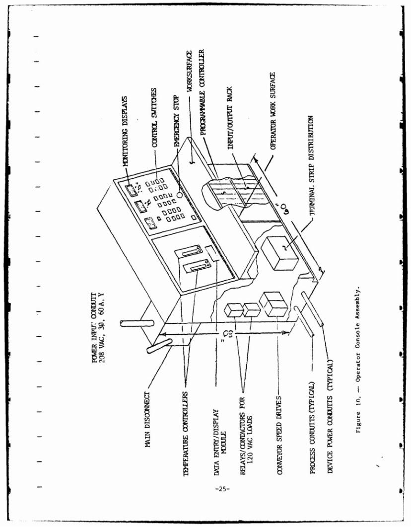
operator control console (Figure 10) serves as the central interface point for all control
operations. The control console provides the operator with the switches for device
activation as well as displays for monitoring system process variables (i.e. pressure,
temperature, and liquid level). The control console functions as the power distribution
center for all the motors, pumps, blowers, and valve actuators.
3t„I Operating Modes
The vacuum infusion system utilizes two operating modes, manual and
automatic. When the system is turned on,it immediately defaults to manual mode. All
displays are energized as well as the indicators that represent current device positions.
In manual mode the operator has direct control over the entire process cycle. Input
commands from the operator are checked against interlock conditions to prevent the
possibility of operating devices out of the necessary safety sequence. Prior to selecting
automatic mode, the operator must accomplish the following:
1. Energize the hot water pump and steam supply system
2. Fill the reservoir with lipoidal liquid
3. Energize the recirculation pump
4. Adjust temperature setpoints
5. Adjust liquid level setpoint
6. Verify all components are operational
7. Allow the system sufficient time to reach setpoint
-24-
m»
F
■ The automatic mode enables the programmable controller to have direct control
over the complete process cycle. The device switches available to the operator in
manual mode are nonfunctional when operating in automatic mode. However, tempera-
ture and liquid level setpoints remain operator adjustable at ail times.
Once automatic mode is selected, the operator initiates the process cycle by
selecting the START sequence switch. The two main responsibilities of the operator
from this point arc: 1) load trays on the entrance conveyor, and 2) pick up trays as they
come off the exit conveyor, 3) ensure sufficient lipoidal liquid is available in the
reservoir.
An exit conveyor limit switch has been provided to prevent trays from jamming or
dropping food on the floor. If a tray is left on the exit conveyor table, the next tray to
come off the conveyor belt will push the previous tray into a limit switch and ail
operations will be suspended until the operator removes the trays from the exit conveyor
table and resets the system from the control console. Critical process cycle times will
not be extended, but operation will stop when timer functions are satisfied.
3.1.1 Safety Considerations
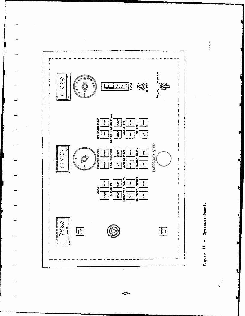
Emergency stop switches are provided at three locations; the operator control
console, the vacuum chamber, and the exit conveyor. Activation of an emergency stop
from any of these three locations will result in loss of power to all field devices (i.e.
motors, pumps, blowers, and valves). The chamber doors, conveyor tables, and tray
carriage remain stationary when power is removed. When the emergency stop condition
is activated an alarm on the control console will sound and operation will be transferred
to manual mode. Once the operator has corrected the situation that caused the
emergency stop, normal operations can be resumed by pressing the Reset switch on the
operator control console (Reference Figure 11).
-40-
' '.1 I i J s a
g s r
■3CI
H5Q3ÜE.III
EEirnirEiuj
«DQlHllE mm §TT
c CO
u o
*-> CO
u <y
a
-27-
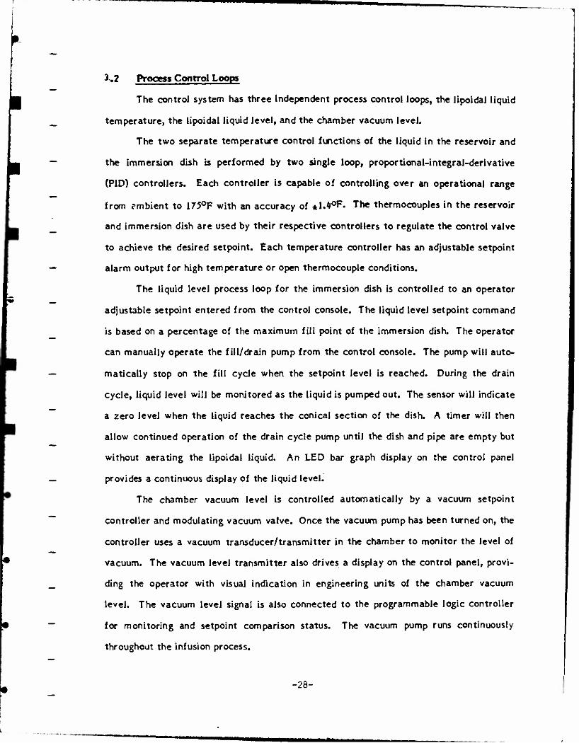
3.2 Process Control Loops
The control system has three independent process control loops, the lipoidal liquid
temperature, the lipoidal liquid level, and the chamber vacuum level.
The two separate temperature control functions of the liquid in the reservoir and
the immersion dish is performed by two single loop, proportional-integral-derivative
(PID) controllers. Each controller is capable of controlling over an operational range
from ?mbient to 175°F with an accuracy of *M°F« The thermocouples in the reservoir
and immersion dish are used by their respective controllers to regulate the control valve
to achieve the desired setpoint. Each temperature controller has an adjustable setpoint
alarm output for high temperature or open thermocouple conditions.
The liquid level process loop for the immersion dish is controlled to an operator
adjustable setpoint entered from the control console. The liquid level setpoint command
is based on a percentage of the maximum fill point of the immersion dish. The operator
can manually operate the fill/drain pump from the control console. The pump will auto-
matically stop on the fill cycle when the setpoint level is reached. During the drain
cycle, liquid level will be monitored as the liquid is pumped out. The sensor will indicate
a zero level when the liquid reaches the conical section of the dish. A timer will then
allow continued operation of the drain cycle pump until the dish and pipe are empty but
without aerating the lipoidal liquid. An LED bar graph display on the control panel
provides a continuous display of the liquid level.
The chamber vacuum level is controlled automatically by a vacuum setpoint
controller and modulating vacuum valve. Once the vacuum pump has been turned on, the
controller uses a vacuum transducer/transmitter in the chamber to monitor the level of
vacuum. The vacuum level transmitter also drives a display on the control panel, provi-
ding the operator with visual indication in engineering units of the chamber vacuum
level. The vacuum level signal is also connected to the programmable logic controller
for monitoring and setpoint comparison status. The vacuum pump runs continuously
throughout the infusion process.
-28-
Once the setpoint is reached, the vacuum level is held by the modulating control valve.
The VAC SETPT indicator on the control panel is energized when the vacuum level
setpoint is reached, and the next cycle step is initiated.
3.3 Sensor Considerations
A key element of the control system is the sensors used for detecting system state
changes. Sensors have been appropriately selected for monitoring temperature, vacuum
level, liquid level, device movements, and water flow.
The temperature sensors selected are Type T thermocouples, these will be used
for all process control signals as well as noncritical monitoring points.
An absolute pressure transducer provides continuous feedback of chamber vacuum
level. This signal is used to provide continuous indication at the control console as well
as close loop control on the vacuum pump isolation valve (VI). An analog roughing gauge
is mounted on the chamber for local indication of the chamber vacuum level.
The liquid level sensor in the immersion dish is an ultrasonic type that provides
continuous feedback of the liquid level from 0 to 6-KJ inches. The sensor is used to *
provide continuous indication, as well as control information for the fill/drain pump
operation.
The ability to detect the movements and positions of various devices is critical to
the sequential operation of the system. Lever actuated limit switches are precisely
located to sense the position of the chamber doors, conveyor tables, product trays, and
specific valves. Adequate adjustment capability has been designed in for easy set up of
switch actuation points.
The water used for cooling the vacuum pump is monitored by a flow switch inter-
lock. The flow switch is a snap action paddle type.
-29-
3.* Drive Motors & Valve Actuators
The drive motors for the conveyor belts are variable speed DC motors. The
operator can adjust the belt speed for each conveyor from the motor drive located inside
the control console.
The motors for the various pumps and blowers are squirrel-cage induction type.
Drawing D12566 shows the motors used in the system and their power requirements.
Motors 1/2 hp and smaller were selected to operate on 208-volt, single-phase, 60-cycle
circuits. Motors larger than 1/2 hp were selected to operate on 208-volt, three-phase,
60-cycle circuits. This best utilizes the efficiencies and current requirements of
available motors. Motor starters used with all motors are full-voltage, across the line,
with integral thermal overloads.
The pneumatic actuators for the system are controlled by electrically operated
solenoid air valves. The solenoids operate from 115-voIt, single-phase, 60-cycle circuits.
3.5 Operational Summary
The following operational summary assumes that the system is adequately
sterilized, that all components are operational, that the conveyor tables are retracted
away from the chamber, and the chamber doors and connecting valves are closed. Refer
to Figure 11 for switch layout on the operator panel.
NOTE: At any point during the cycle, in either automatic or manual mode, the operator can immediately stop the system by pressing any of the three EMERGENCY STOP switches.
1. Turn the power on by pressing the POWER switch on the control panel at the operator console.
the audible alarm will sound, the operator should press the RESET switch to clear the system
the digital displays should energize and show values reflective of the current system status
system operations default to manual mode
-30-

the switch indicator lights show the current position and state of each device in the system.
2. Verify the reservoir has an adequate supply of liquid for operation, fill ar required.
3. Manual mode operations:
start the hot water pump by pressing the corresponding START switch
enter the temperature setpoints on the temperature controller as per manufacturer's instructions.
start the recirculation pump by pressing the corresponding START switch
start the vacuum pump by pressing the corresponding START switch.
enter the immersion dish liquid level setpoint by adjusting the level select dial to the desired percent of full (0-100%)
start the chiller by pressing the corresponding START switch
i*. Allow sufficient time for the temperature of the liquid in the reservoir to achieve the setpoint. The temperature can be continuously monitored on the displays. Each of the temperature displays has a selector switch associated with it. The process display has a two-position switch, and the monitor display has a five position switch. Table 1 lists the temperature data displayed for each switch selection.
TABLE 1
Temperature Displays
Device Switch Setting
Process Display
Process Display
Monitor Display
Monitor Display
Monitor Display
Monitor Display
Monitor Display
Data
Immersion Dish Infusion Liquid
2 Reservoir Infusion Liqu
1 Circulating hot water
2 Ambient inside Vacuum Chamber
3 Cold air
k Warm air
5 to 12 Spares
-31-
5. Prior to starting the cycle, the operator should load product trays on the entrance conveyor, the first tray should be positioned such that it actuates the entrance limit switch. Subsequent trays should be po-itioned with a minimum of six-inch spacing between trays.
6. Manual sequential operations:
a. Open the chamber doors by pressing the chamber door OPEN switch.
b. Cycle the conveyor tables in by pressing the conveyor table IN switch.
c. Cycle the product tray into the chamber by pressing the conveyor motor ON switch. The steam bath for each conveyor belt will be energized while the belt is moving - the entrance conveyor belt will stop automatically when the next product tray moves to the end of the belt. The exit conveyor belt stops when the product tray is positioned under the chiller hood. If desired both belts can be stopped by pressing the conveyor motor OFF switch.
d. Retract the conveyor tables by pressing the conveyor table OUT switch.
e. Close the chamber doors by pressing the chamber door CLOSE switch.
f. Lower the product tray by pressing the tray position DOWN switch.
g. Start the vacuum cycle by pressing VAC SETPOINT switch. This opens the isolation valve between the pump and the chamber.
- Monitor the vacuum level through the display, when the setpoint is reached the VAC SETPT indicator will light.
- When the setpoint is reached the isolation valve will modulate to maintain setpoint. Keep the vacuum pump running at all times.
- The operator can stop the vacuum pump at any point by pressing the STOP switch.
h. Fill the immersion dish to the selected setpoint level by holding the FILL/DRAIN switch in the FILL position. The LED display provides an indication of the liquid level in the dish.
- the fill/drain pump and the isolation valve operate automatically when the switch is selected.
- a high level override will automatically de-energize the pump and close the valve if a preset high level limit value is reached.
-32-
i. The dwell time measurement is started when the level setpoint is reached. The dwell period is operator adjustable from the Timer Display Module. The operator can raise the tray at any point before the dwell time cycle completes by pressing the tray position Up switch.
- When the time period is completed the vacuum is released by vacuum break valve.
- The product tray is raised from the liquid and permitted to drain into the immersion dish.
- The tray may be shaken after it has been removed from the liquid. This feature promotes the removal of excess liquid from the food and tray. Shake time is adjustable from zero up to the required time period.
- Empty the immersion dish by holding the FILL/DRAIN switch in the DRAIN position - the fill/drain pump and the isolation valve will automatically de- energize when the immersion dish is empty.
Open the warm air valve and start the blower by pressing the warm air ON switch.
- The blower will assist in removal of excess liquid from the product trays as the trays cycle out.
Remove the processed food tray by the conveyor and operate conveyor until tray is positioned under chiller hood.
j. Repeat steps b through i.
The steps outlined in the previous sections are described as manual mode
operation. These steps will be automatically and sequentially performed in auto mode.
Select auto mode by pressing the AUTO switch on the control panel. The operator's
primary responsibility in auto mode will be loading and removal of the product trays.
Thii docuatnt rtporti rtitaroh undfrtaktn at tht US Army »«tick RtMarch, Davflopmnt and Rnglntfring Ctntfr and had bt«n aaiignad Mo. UncX/TJi-$$/t>7trin th. tariff of rfportt approvfd for publication.
-33-
APPENDIX A
COMPONENT SPECIFICATIONS
-J3-
1 - COMPONENT SPECIFICATIONS
General
Proof of conformance with contract code requirements: Where materials or
equipment are specified to conform to requirements of the Underwriters Laboratories,
Inc., or the Factory Mutual System, the Contractor shall submit proof of such
conformance. The label or listing of the specified agency will be acceptable evidence.
In lieu of the label or listing, the Contractor may submit a written certificate, from any
approved nationally recognized testing organization adequately equipped and competent
to perform such service, stating that the items have been tested and that the units
conform to the requirements, including methods of testing, of the specified agency.
Where equipment is specified to conform to requirements of the ASME Boiler and
Pressure Vessel Code, the design, fabrication, and installation shall conform to the code
in every respect, except that code stamping is not required
0 Method of Construction: As much as practical, equipment shall be
mounted on a minimum number of bases to facilitate site installation and
relocation at a later date. All utilities and service lines shall terminate
at one general location of the completed unit to facilitate hook up after
installation.
0 Workmanship: Workmanship shall be of the highest grade throughout and
in accordance with the best standard practice for this type of equipment.
Castings and other parts shall fit accurately and shall be tight where
necessary. In joint pieces of similar metal, fastening devices and metal
used for welding shall be of the same material as the metal being joined.
When corrosion-resisting steel is joined to dissimilar metal, fastening
devices and metal used for welding shall be corrosion-resisting steel.
Chromium plating, where used, shall be applied over nickel plating.
-37-
Name plates; Each major item of equipment shall have the
manufacturer's name, address, and catalog number on a plate securely
attached to the item.
Safety Requirements: Belts, pulleys, chains, gears, couplings, projecting
setscrews, keys, and other rotating parts shall be fully enclosed or
properly guarded. High-temperature equipment and piping so located as
to endanger personnel or create a fire hazard shall be properly guarded
or covered with insulation of a type as specified.
Verification of Dimensions: The contract drawings show the extent and
general arrangement of the vacuum infusion system. The Contractor
shall visit the premises to, be thoroughly familiar with all details
of the work and working conditions. Final arrangement shall be to suit
actual site installation area.
Coordination of Trades: The Contractor shall be specifically responsible
for the coordination and proper relation of his/her work to the
building structure and to the work of all trades.
Materials: Materials and Equipment shall conform to the respective
publications and other requirements specified below. Other materials
and equipment shall be as specified elsewhere herein and as shown, and
shall be the products of manufacturers regularly engaged in such
manufacture. Items of equipment shall essentially duplicate equipment
that has been in satisfactory use at least two years prior to bid opening
and shall be supported by a service organization.
-38-

Welding
Welding shall be done in a thorough manner with welding rod of compatible
composition with the sheets or parts to be welded. Welds shall be strong and ductile,
with excess metal on exposed working surfaces ground off and joints finished smooth to
match adjoining surfaces. Welds shall be free of imperfections such as pits, runs,
spatter, and cracks, and shall have the same color as the adjoining surfaces. Joints shall
be welded by some process other than by carbon-arc welding or any process that permits
carbon pickup. Butt welds made by welding straps under seams, by filling in with solder,
and by grinding, will not be acceptable. Welded joints shall be homogeneous with the
sheet metal. In no case shall spot welding be substituted for full welding. Where sheet
sizes necessitate a joint, such joint shall be welded.
Vacuum Chamber
o Design and fabricate in accordance with ASME Pressure Vessel Code Section VIII, Division I.
o Operating Pressure: i torr to 20 Ps^9-
o Operating Temperature: 60°toi50°r7-
o Door hinge assembly shall be designed to provide 2 psi minimum force on door seal with 100 'psig air supply cylinders.
o For additional details reference drawing D12557.
Food Tray Conveyor:
o Maximum loading of (3) three trays (each 2*M x 12") at 10 lbs. (5 lbs./sq.ft.) each.
o Variable speed D.C. motor with speed reducer to provide belt speed of 0 to 30 feet per minute.
o All components used shall be rated for washdown use.
o All materials contacting the food product shall be compatible with all applicable food service requirements.
o For additional details reference drawings D12559 and D12560.
-39-
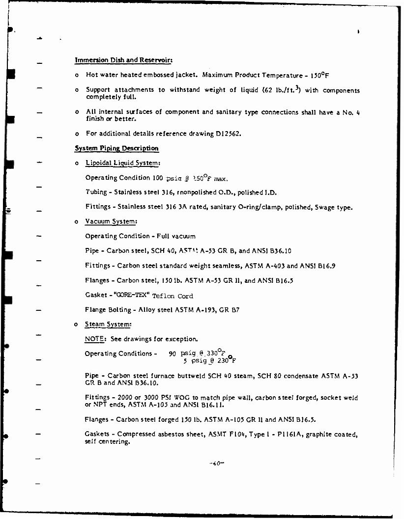
Immersion Dish and Reservoir;
o Hot water heated embossed jacket. Maximum Product Temperature - 150°F
o Support attachments to withstand weight of liquid (62 lb./ft.^) with components completely full.
o All internal surfaces of component and sanitary type connections shall have a No. 4 finish or better.
o For additional details reference drawing D12562.
System Piping Description
o Lipoidal Liquid System:
Operating Condition 100 psiq £ I50°f max.
Tubing - Stainless steel 316, rnonpolished O.D., polished I.D.
Fittings - Stainless steel 316 3A rated, sanitary O-ring/clamp, polished, Swage type,
o Vacuum System:
Operating Condition - Full vacuum
Pipe - Carbon steel, SCH 40, AST*'. A-53 GR B, and ANSI B36.10
Fittings - Carbon steel standard weight seamless, ASTM A-403 and ANSI B16.9
Flanges - Carbon steel, 150 lb. ASTM A-53 GR II, and ANSI B16.5
Gasket - "GORE-TEX" Teflon Cord
Flange Bolting - Alloy steel ASTM A-193, GR B7
o Steam System:
NOTE: See drawings for exception.
Operating Conditions - 90 psig @.330°F 5 psig_@ 230 F
Pipe - Carbon steel furnace buttweld SCH 40 steam, SCH 80 condensate ASTM A-53 GR Band ANSI B36.10.
Fittings - 2000 or 3000 PSI WOG to match pipe wall, carbon steel forged, socket weld or NPT ends, ASTM A-105 and ANSI B16.ll.
Flanges - Carbon steel forged 150 lb. ASTM A-105 GR II and ANSI B16.5.
Gaskets - Compressed asbestos sheet, ASMT F104, Type I - PI 161 A, graphite coated, self centering.
-40-
.
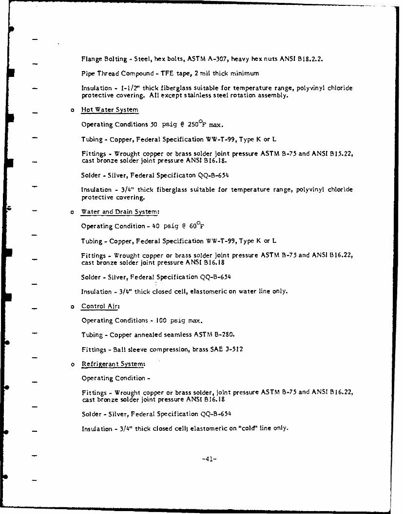
Flange Bolting - Steel, hex bolts, ASTM A-307, heavy hex nuts ANSI B 18.2.2.
Pipe Thread Compound - TFE tape, 2 mil thick minimum
Insulation - 1-1/2*' thick fiberglass suitable for temperature range, poly vinyl chloride protective covering. All except stainless steel rotation assembly.
o Hot Water System
Operating Conditions 50 psig @ 250°F max.
Tubing - Copper, Federal Specification WW-T-99, Type K or L
Fittings - Wrought copper or brass solder joint pressure ASTM B-75 and ANSI B 15.22, cast bronze solder joint pressure ANSI B16.18.
Solder - Silver, Federal Specificaton QQ-B-654
Insulation - 3/4" thick fiberglass suitable for temperature range, polyvinyl chloride protective covering.
o Water and Drain System:
Operating Condition - 40 psig @ 60 F
Tubing - Copper, Federal Specification WW-T-99, Type K or L
Fittings - Wrought copper or brass solder joint pressure ASTM B-75 and ANSI B 16.22, cast bronze solder joint pressure ANSI B16.18
Solder - Silver, Federal Specification QQ-B-654
Insulation - 3/4" thick closed ceil, elastomeric on water line only.
o Control Air;
Operating Conditions - 100 psig max.
Tubing - Copper annealed seamless ASTM B-280.
Fittings - Ball sleeve compression, brass SAE J-512
o Refrigerant System:
Operating Condition -
Fittings - Wrought copper or brass solder, joint pressure ASTM B-75 and ANSI B 16.22, cast bronze solder joint pressure ANSI B16.18
Solder - Silver, Federal Specification QQ-B-654
Insulation - 3/4" thick closed cell; elastomeric on "cold" line only.
-41-
I
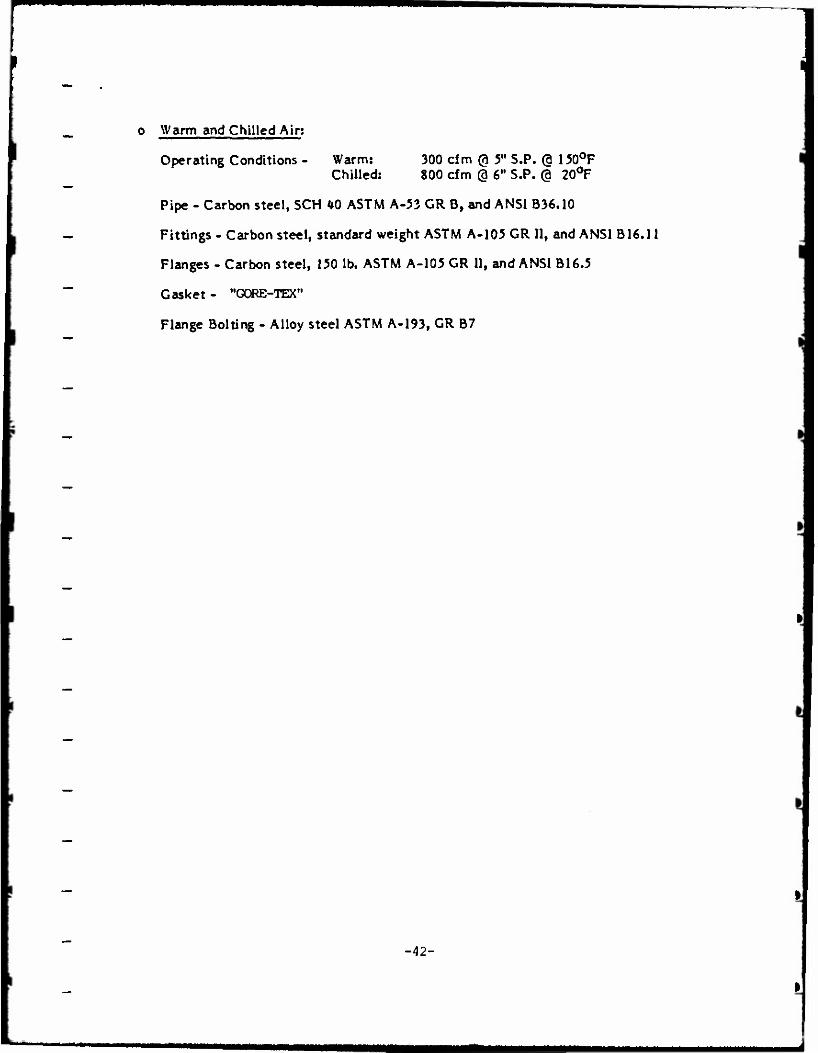
o Warm and Chilled Air;
Operating Conditions - Warm: 300 cfm @ 5" S.P. @ 150°F Chilled: 800 cfm @ 6" S.P. @ 20°F
Pipe - Carbon steel, SCH <*0 ASTM A-53 GR B, and ANSI B36.10
Fittings - Carbon steel, standard weight ASTM A-105 GR II, and ANSI B16.ll
Flanges - Carbon steel, 150 lb. ASTM A-105 GR II, and ANSI B16.5
Gasket- "GORE-TEX"
Flange Bolting - Alloy steel ASTM A-193, GR B7
-42-
APPENDIX B
BILL OF MATERIAL
-43-
MMMNHWW
1
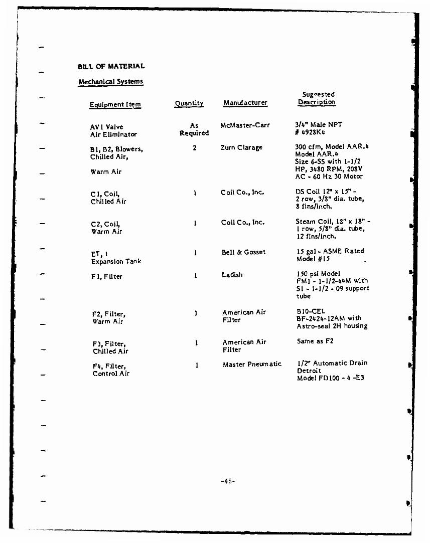
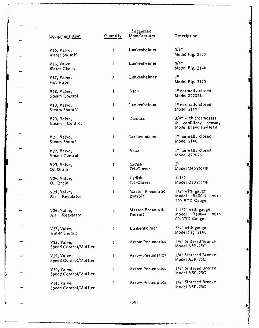
BILL OF MATERIAL
Mechanical Systems
Equipment Item Quantity Manufacturer Suggested
Description
AVI Valve Air Eliminator
As Required
McMaster-Carr 3M" Male NPT # 192SK«
Bl, B2, Blowers, Chilled Air,
Warm Air
2 Zurn Oarage 300 cfm, Model AAR.« Model AAR.fc Size 6-SS with 1-1/2 HP, 3*80 RPM, 20SV AC - 60 Hz 30 Motor
Ci, Coil, Chilled Air
1 Coil Co., Inc. DSCoU 12" x 15"- 2 row, 3/8" dia. tube, 8 fins/inch.
C2, Coil, Warm Air
1 Coil Co., Inc. Steam Coil, 18" x 18" - 1 row, 5/8" dia. tube, 12 fins/inch.
ET, 1 Expansion Tank
1 Bell & Gösset 15 gal - AS ME Rated Model n 15
Fl, Filter 1 Ladish 150 psi Model FM1 - 1-1/2-MM with SI - 1-1/2 - 09 support tube
F2, Filter, Warm Air
1 American Air Filter
B10-CEL BF-2W-12AM with Astro-seal 2H housing
F3, Filter, Chilled Air
1 American Air Filter
Same as F2
F4. Filter. 1 Master Pneumatic 1/2" Automatic Drain
Control Air Detroit Model FD100-4-E3
-45-
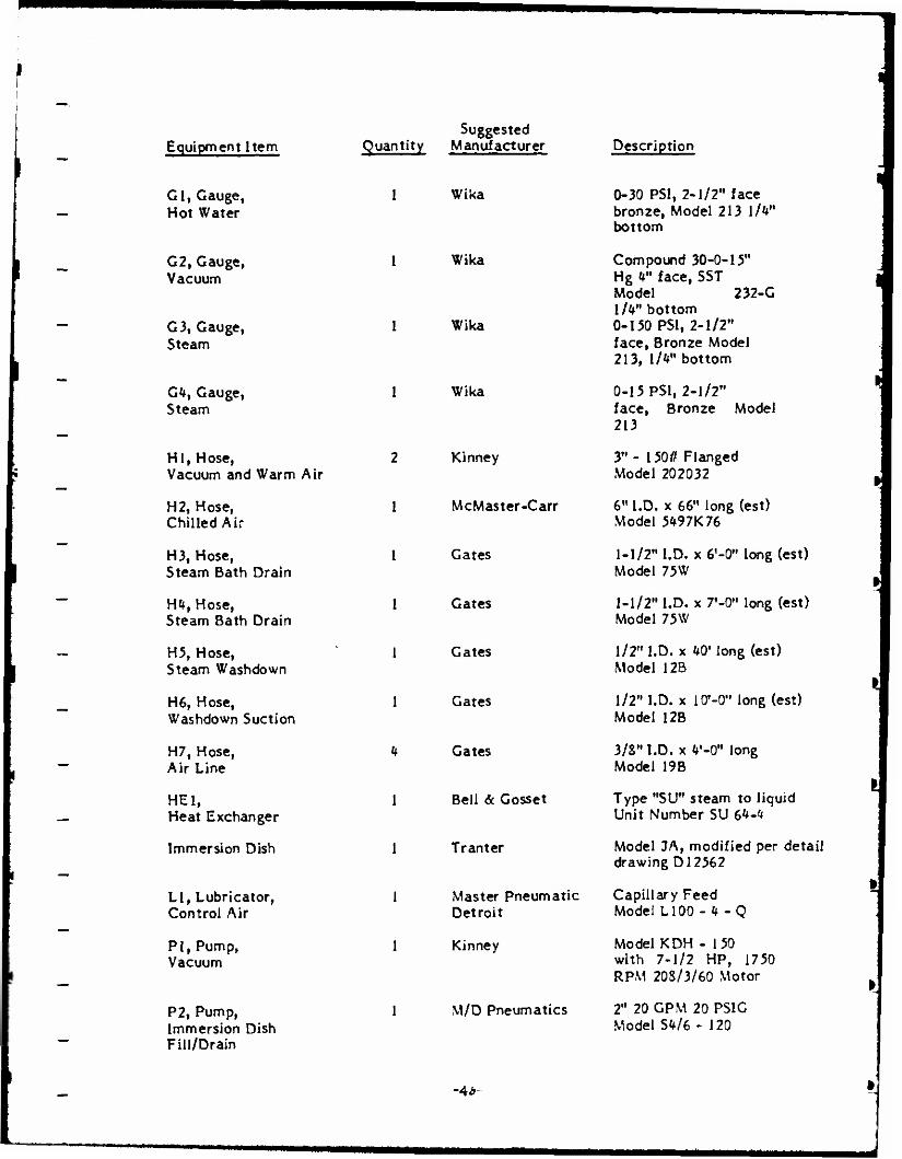
Equipment Item Suggested
Quantity Manufacturer Description
Cl, Gauge, Hot Water
G2, Gauge, Vacuum
G 3, Gauge, Steam
G*, Gauge, Steam
HI, Hose, Vacuum and Warm Air
H2, Hose, Chilled Air
H3, Hose, Steam Bath Drain
m, Hose, Steam Bath Drain
H5, Hose, Steam Washdown
H6, Hose, Washdown Suction
H7, Hose, Air Line
HEl, Heat Exchanger
Immersion Dish
LI, Lubricator, Control Air
PI, Pump, Vacuum
P2, Pump, Immersion Dish Fill/Drain
1 Wika
1 Wika
1 Wika
1 Wika
2 Kinney
1 McMaster-Carr
1 Gates
1 Gates
1 Gates
1 Gates
U Gates
1 Bell & Gösset
1 Tranter
1 Master Pneumatic Detroit
1 Kinney
M/D Pneumatics
0-30 PSI, 2-1/2" face bronze, Model 213 1/fc" bottom
Compound 30-0-15" Hg H" face, SST Model 232-G l/U" bottom 0-150 PSI, 2-1/2" face, Bronze Model 213, 1 A" bottom
0-15 PSI, 2-1/2" face, Bronze Model 213
3"- 150// Flanged Model 202032
6" I.D. x 66" long (est) Model 5497K76
1-1/2" I.D. x 6'-0" long (est) Model 75W
1-1/2" I.D. x 7'-0" long (est) Model 75W
1/2" I.D. x 40' long (est) Model 12B
1/2" I.D. x lO'-O" long (est) Model 12B
3/8" I.D. x V-0" long Model 19B
Type "SU" steam to liquid Unit Number SU 6^-t*
Model JA, modified per detail drawing D12562
Capillary Feed Model L100 -4 - Q
Model KDH - 150 with 7-1/2 HP, 1750 RPM 20S/3/60 Motor
2" 20 GPM 20 PSIG Model SW6 - 120
-Ab-
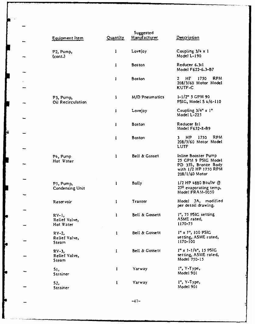
Equipment Item
P2, Pump, (cont.)
P3, Pump, Oil RecircuJation
pt*, Pump Hot Water
P5, Pump, Condensing Unit
Reservoir
RV-1, Relief Valve, Hot Water
RV-2, Relief Valve, Steam
RV-3, Relief Valve, Steam
SI, Strainer
S2, Strainer
Suggested Quantity Manufacturer
Lovejoy
Boston
Boston
M/D Pneumatics
Lovejoy
Boston
Boston
Bell & Cosset
Description
Coupling 3/*» x 1 Model L-190
Reducer 6.3:1 Model F622-6.3-B7
2 HP 1750 RPM 208/3/60 Motor Model KUTF-C
1-1/2" 5 CPM 90 PSIG, Model S 4/6-110
Coupling 3/V x 1" Model 1-225
Reducer 8:1 Model F632-8-B9
3 HP 1750 RPM 208/3/60 Motor Model LUTF
Inline Booster Pump 25 GPM 9 PSIG Model PD 35S, Bronze Body with 1/2 HP 1750 RPM 208/1/60 Motor
Bally 1/2 HP 4880 Btu/hr @ 1 25° evaporating temp. J Model FRAM-0050 1
Tranter Model JA, modified 1 per detail drawing. 1
Bell & Gossett 1", 75 PSIG setting 1 ASME rated, 1170-75
Bell & Gossett 1" x 1", 100 PSIG setting, ASME rated, 1170-100
Bell <3c Gossett l"x 1-1/*", 15 PSIG !
setting, ASME rated, Model 750-15
Yarway 1", Y-Type, Model 901
Yarway 1", Y-Type, Model 901
-47-
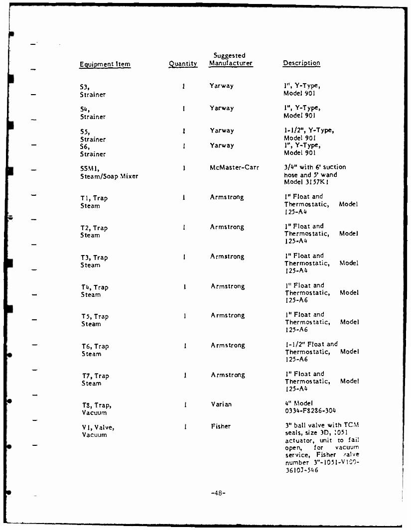
Equipment Item £ Suggested
uantity Manufacturer Description
S3, Strainer
1 Yarway 1», Y-Type, Model 901
Strainer 1 Yarway 1«, Y-Type,
Model 901
S5, Strainer S6, Strainer
1 Yarway
1 Yarway
1-1/2", Y-Type, Model 901 1", Y-Type, Model 901
SSM1, Steam/Soap Mixer
1 McMaster-Carr 3/<»" with 6' suction hose and 5' wand Model 3157K1
Tl,Trap Steam
1 Armstrong I" Float and Thermos tatic, 125-Mt
Model
T2, Trap Steam
I Armstrong 1" Float and Thermos tatic, 125-Ai*
Model
T3, Trap Steam
1 Armstrong 1" Float and Thermos tatic, 125-Ai*
Model
T*, Trap Steam
1 Armstrong I" Float and Thermostatic, 125-A6
Model
T5, Trap Steam
1 Armstrong I" Float and Thermostatic, 125-A6
Model
T6, Trap Steam
I Armstrong 1-1/2" Float and Thermostatic, 125-A6
Model
T7, Trap Steam
I Armstrong 1" Float and Thermostatic, 125-A4
Model
T8, Trap, Vacuum
1 Varian <*" Model 033*»-F8286-304
VI, Valve, Vacuum
1 Fisher 3" ball valve wit seals, size 3D, 1
hTCM 051
actuator, unit to fail open, for vacuum service, Fisher /alve number 3"-1051-VI00- 36103-5^6
-48-
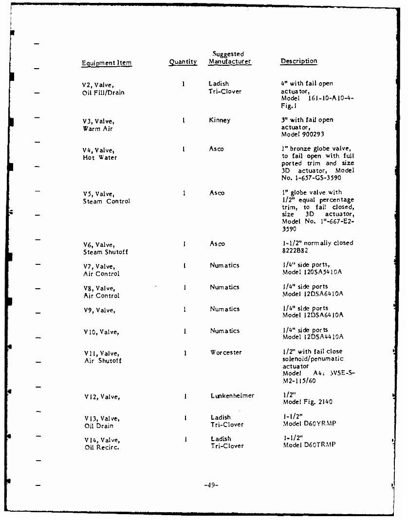
Equipment Item
V2, Valve, Oil Fill/Drain
V3, Valve, Warm Air
VU, Valve, Hot Water
V5, Valve, Steam Control
V6, Valve, Steam Shutoff
V7, Valve, Air Control
V8, Valve, Air Control
V9, Valve,
ViO, Valve,
V11, Valve, Air Shutoff
V12, Valve,
VI3, Valve, Oil Drain
Vl^, Valve, Oil Recirc.
Suggested Quantity Manufacturer
1 Ladish Tri-Clover
Kinney
Asco
Description
4" with fail open actuator, Model 161-10-A10-4- Fig.l
3" with fail open actuator, Model 900293
I" bronze globe valve, to fail open with full ported trim and size 3D actuator, Model No. 1-657-GS-3590
1 Asco 1" globe valve with 1/2" equal percentage trim, to fail closed, size 3D actuator, j Model No. l"-667-E2- 3590
1 Asco 1-1/2" normally closed 8222B82
1 Numatics Uk" side ports, !
Model 120SA5M0A
1 Numatics \lk" side ports Model 12DSA6M0A
1 Numatics Ilk" side ports \ Model 12DSA6M0A
I Numatics llUn side ports Model 12DSAW0A
1 Worcester 1/2" with fail close j solenoid/penuma tic actuator Model M*L 3VSE-S- M2-115/60 |
1 Lunkenheimer 1/2" l Model Fig. 2140
1 Ladish Tri-Clover
1-1/2" Model D60YRMP
1 Ladish Tri-Clover
1-1/2" % Model D60TRMP
-49-
Equipment Item Suggested
Quantity Manufacturer Description
I
l
V15, Valve, Water Shutoff
V16, Valve, Water Check
V17, Valve, Hot Water
V18, Valve, Steam Control
V19, Valve, Steam Shutoff
V20, Valve, Steam Control
V21, Valve, Steam Shutoff
V22, Valve, Steam Control
V23, Valve, Oil Drain
V24, Valve, Oil Drain
V25, Valve, Air Regulator
V26, Valve, Air Regulator
V27, Valve, Water Shutoff
V28, Valve, Speed Control/Muffler
V29, Valve, Speed Control/Muffler
V30, Valve, Speed Control/Muffler
V31, Valve, Speed Control/Muffler
Lunkenheimer
Lunkenheimer
Lunkenheimer
A sco
Lunkenheimer
Dan f oss
Lunkenheimer
As co
Ladish Tri-CIover
Ladish Tri-CIover
Master Pneumatic Detroit
Master Pneumatic Detroit
Lunkenheimer
Arrow Pneumatics
Arrow Pneumatics
Arrow Pneumatics
Arrow Pneumatics
3/4" Model Fig. 2140
3/V Model Fig. 2144
1" Model Fig. 2140
1" normally closed Model 822026
l" normally closed Model 2140
3/4" with thermostat <5c capilliary sensor, Model Bravo Hi-Head
1" normally closed Model 2140
1" normally closed Model 822026
2" Model D60YRMP
1-1/2" Model D60YRMP
1/2" with gauge Model R100-4 with 200-BDD Gauge
1-1/2" with gauge Model R100-4 with 60-BDD Gauge
3/4" with gauge Model Fig. 2140
1/4" Sintered Bronze Model ASP-2SC
1/4" Sintered Bronze Model ASP-2SC
1/4" Sintered Bronze Model ASP-2SC
1/4" Sintered Bronze Model ASP-2SC
-50-
I
I
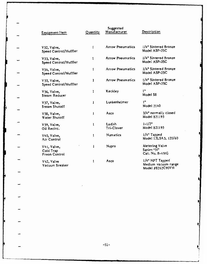
Equipment Item
V32, Valve, Speed Control/Muffler
V33, Valve, Speed Control/Muffler
V34, Valve, Speed Control/Muffler
V35, Valve, Speed Control/Muffler
V36, Valve, Steam Reducer
V37, Valve, Steam Shutoff
V38, Valve, Water Shutoff
V39, Valve, Oil Recirc.
V40, Valve, Air Control
V41, Valve, Cold Trap Freon Control
V42, Valve Vacuum Breaker
Suggested Quantity Manufacturer
Arrow Pneumatics
Arrow Pneumatics
Arrow Pneumatics
Arrow Pneumatics
Description
1/4" Sintered Bronze Model ASP-2SC
1/4" Sintered Bronze Model ASP-2SC
1/4" Sintered Bronze Model ASP-2SC
1/4" Sintered Bronze Model ASP-2SC
Keckley 1" Model S8
Lun kenne im er r Model 2140
Asco 3/4" normally closed Model 821195
Ladish Tri-Clover
1-1/2" Model 821195
Numatics 1/4" Tapped Model 13LSA3, 120/60
Nupro Metering Valve Series "M" Cat. No. B-4MG
Asco 1/4" NPT Tapped Medium vacuum range Model //8262C90VM
-51- 1
•m^^m^^mmm mmm
' -
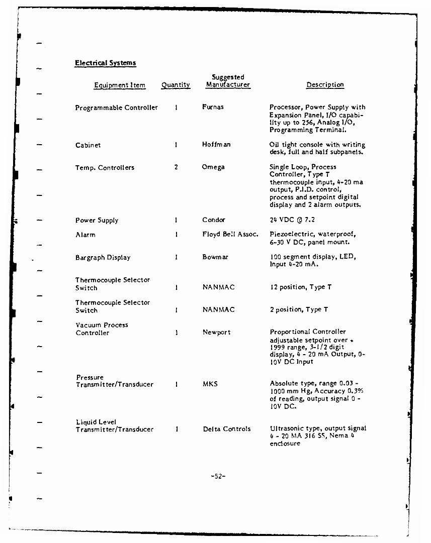
Electrical Systems
Equipment Item Quantity Suggested
Manufacturer Description
Programmable Controller 1
Cabinet
Temp. Controllers
Power Supply
Alarm
Bargraph Display
Thermocouple Selector Switch
Thermocouple Selector Switch
Vacuum Process Controller
Pressure Transmitter/Transducer
Liquid Level Transmitter/Transducer
Furnas
Hoffman
Omega
Condor
Floyd Bell Assoc.
Bowmar
NANMAC
NANMAC
Newport
MKS
Processor, Power Supply with Expansion Panel, I/O capabi- lity up to 256, Analog I/O, Programming Terminal.
Oil tight console with writing desk, full and half subpanels.
Single Loop, Process Controller, Type T thermocouple input, 4-20 ma output, P.l.D. control, process and setpoint digital display and 2 alarm outputs.
24 VDC @ 7.2
Piezoelectric, waterproof, 6-30 V DC, panel mount.
100 segment display, LED, Input 4-20 mA.
12 position, Type T
Delta Controls
2 position, Type T
Proportional Controller adjustable setpoint over ♦ 1999 range, 3-1/2 digit displayt 4-20 mA Output, 0- 10V DC Input
Absolute type, range 0.03 - 1000 mm Hg, Accuracy 0.3^ of reading, output signal 0 - 10V DC.
Ultrasonic type, output signal 4-20 MA 316 SS, Nema 4 enclosure
-52-
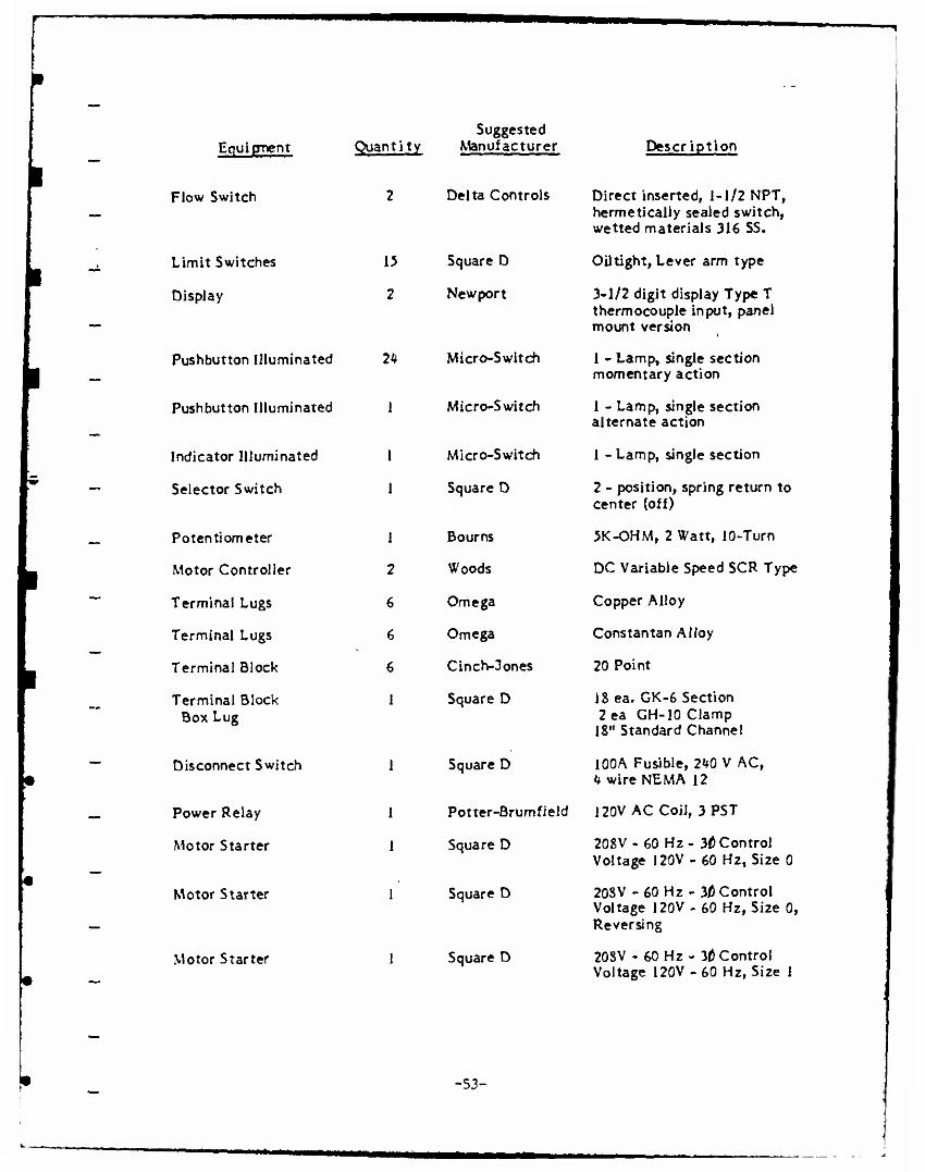
Equipment
Flow Switch
Limit Switches
Display
Pushbutton Illuminated
Pushbutton Illuminated
Indicator Illuminated
Selector Switch
Potentiometer
Motor Controller
Terminal Lugs
Terminal Lugs
Terminal Block
Terminal Block Box Lug
Disconnect Switch
Power Relay
Motor Starter
Motor Starter
Motor Starter
Quantity Suggested
Manufacturer Description
2 Delta Controls Direct inserted» 1-1/2 NPT, hermetically sealed switch, wetted materials 316 5S.
15 Square D OUtight, Lever arm type
2 Newport 3-1/2 digit display Type T thermocouple input, panel mount version
7k Micro-Switch 1 - Lamp, single section momentary action
1 Micro-Switch 1 - Lamp, single section alternate action
1 Micro-Switch 1 - Lamp, single section
1 Square D 2 - position, spring return to center (off)
1 Bourns 5K-OHM, 2 Watt, 10-Turn
2 Woods DC Variable Speed SCR Type
6 Omega Copper Alloy
6 Omega Constantan Alloy
6 Cinch-3ones 20 Point
1 Square D 18 ea. GK-6 Section
Square D
Potter-Brumfield
Square D
Square D
Square D
2ea GH-10 Clamp 18" Standard Channel
100A Fusible, 2<*0 V AC, k wire NEMA 12
120V AC Coil, 3PST
208V - 60 Hz- 30 Control Voltage 120V - 60 Hz, Size 0
208V - 60 Hz- 30 Control Voltage 120V - 60 Hz, Size 0, Reversing
208V - 60 Hz - 3f) Control Voltage 120V -60 Hz, Size I
-53-
*MB*

I Equipment
Motor Starter
Quantity
2
Suggested Manufacturer
Square D
Motor Starter 2 Square D
Circuit Breaker 1 Square D
Circuit Breaker 1 Square D
Circuit Breaker 1 Square D
Circuit Breaker 2 Square D
Control Relays 10 Potter-Brumfield
Fuse Block 6 Square D
Description
208V - 60 Hz - 30 Control Voltage 120V - 60 Hz, Size 00
20SV -60 Hz- 10 Control Voltage 120V - 60 Hz
100A Frame Thermal - mag, 3 Pole, 35 Amp
100A Frame Thermal - mag, 3 Pole, 25 Amp
100A Frame Thermal - mag, 3 Pole, 15 Amp
100A Frame Thermal - mag, 2 Pole, 15 Amp
2W DC Coil with Socket
Single Circuit
-54-
APPENDIX C
CONSTRUCTION STRATEGY
-55-
^^^
_ Construction Strategy
All materials and equipment shall be installed in accordance with the approved
— recommendations of the manufacturer to conform with the contract documents. The
installation shall be accomplished by workmen skilled in this type of work.
Method of Construction
As much as practical, equipment shall be mounted on a minimum number of bases to
facilitate site installation and relocation at a later date. All utilities and service lines
1 — shall terminate at one general location of the completed unit to facilitate hook up after
installation.
Wiring and Conduit shall be installed as follows:
All fabrication and wiring of components internal to the control console (Figure 10)
shall be accomplished and checked before delivery to the site. All component wiring
— external to the control console shall be performed at the site.
0 Conduit shall be routed to avoid any interface with mechanical equipment, and piping.
0 Conduit shall be rigid aluminum unless otherwise noted.
0 All wiring shall be single conductor stranded copper, NEC type THWN size as noted.
Pipe shall be installed as follows:
— ° Unless otherwise specified herein, pipe and fitting shall conform to the requirements of ANSI B31.1.
0 Pipe shall be cut accurately to measurements established at the job site, worked into ~ place without springing or forcing, and properly clear windows, doors, and other
openings. Cutting or other weakening of the building structure to facilitate piping installation will not be permitted.
0 Pipes shall have burrs removed by reaming, and shall be so installed as to permit free expansion and contraction without causing damage to building structure, pipe, joints,
__ or hangers.
° Changes in direction shall be made with fittings, except that bending of pipe up to four inches will be permitted, provided a pipe bender is used and wide sweep bends
"" are formed. The center line radius of bend shall be not less than six diameters of the pipe. Bent pipe showing kinks, wrinkles, flattening or other malformations will not be accepted.
-56-

Horizontal mains shall pitch up or down in the direction of flow. The grade shall be not less than 1 inch in 40 feet.
Reduced fittings shall be used for changes in pipe sizes.
Open ends of pipelines and equipment shall be properly capped or plugged during installation to keep dirt or other foreign materials out of the systems.
Pipe not otherwise specified shall be uncoated.
0 Connections between ferrous and copper piping shall be electrically isolated from each other with dielectric unions and meet the joint requirements.
Joints shall be made up as follows:
° Ream all pipe ends before joint connections are made.
0 Screwed joints shall be made up with a teflon filled compound and not more than three threads shall show after joint is made-up.
0 Joint compounds shall be applied to the male thread only, and care shall be exercised to prevent compound from reaching the interior of the pipe.
° Screwed unions, welded unions or bolted flanges shall be provided wherever required to permit convenient, maintenance-wise removal of equipment, valves, and piping accessories from the piping system.
0 Field welded joints shall conform to the requirements of the A WS, ANSI B31.1-1973, and the requirements of Division 17 -"Welding, Brazing and Soldering".
° Flanged joints shall be assembled with appropriate flanges, gaskets, and bolting, the clearance between flange faces shall be such that the connections can be gasketed and bolted tight without imposing undue strain on the piping system.
0 Copper tubing for solder joints cr.-ll be cut square and burrs shall be removed with approved cutting and reaming tools. Inside surfaces of fittings and outside surfaces of tubes in joint area shall be cleaned with steel wool before assembly of joint. Joint flux, filler material and heat source shall be applied in accordance with the manufac- turer's instructions to provide proper capillary action to fill the socket space and to achieve 100 percent of shear-line strength capability. Valves in copper piping shall have screwed ends with end adapters to suit mechanical connections, unless solder jointing is specified or indicated for a given application. Copper joints which fail pressure tests shall be remade with new materials including pipe or tubing fitting, and filler metal.
Copper tubing with mechanical joints shall be rut square and burrs shall be removed with approved cutting and reaming tools. Care shall be exercised to not work hardened copper surfaces and in case of doubt, tube ends shall be cut off or annealed by heating to a temperature and air cooling in accordance with the manufacturer's instructions.
-57-
mmma
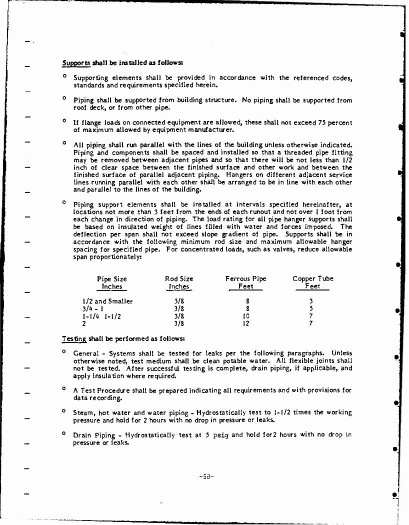
Supports shall be installed as follows
0 Supporting elements shall be provided in accordance with the referenced codes, standards and requirements specified herein.
0 Piping shall be supported from building structure. No piping shall be supported from roof deck, or from other pipe.
° If flange loads on connected equipment are allowed, these shall not exceed 75 percent of maximum allowed by equipment manufacturer.
0 All piping shall run parallel with the lines of the building unless otherwise indicated. Piping and components shall be spaced and installed so that a threaded pipe fitting may be removed between adjacent pipes and so that there will be not less than 1/2 inch of clear space between the finished surface and other work and between the finished surface of parallel adjacent piping. Hangers on different adjacent service lines running parallel with each other shall be arranged to be in line with each other and parallel to the lines of the building.
0 Piping support elements shall be installed at intervals specified hereinafter, at locations not more than 3 feet from the ends of each runout and not over 1 foot from each change in direction of piping. The load rating for all pipe hanger supports shall be based on insulated weight of lines filled with water and forces imposed. The deflection per span shall not exceed slope gradient of pipe. Supports shall be in accordance with the following minimum rod size and maximum allowable hanger spacing for specified pipe. For concentrated loads, such as valves, reduce allowable span proportionately:
Pipe Size Rod Size Ferrous Pipe Copper Tube Inches Inches Feet Feet
1/2 and Smaller 3/8 8 3 3/4 - 1 3/8 8 5 I-]/« 1-1/2 3/8 10 7 2 3/8 12 7
Testing shall be performed as follows:
0 General - Systems shall be tested for leaks per the following paragraphs. Unless otherwise noted, test medium shall be clean potable water. All flexible joints shall not be tested. After successful testing is complete, drain piping, if applicable, and apply insulation where required.
0 A Test Procedure shall be prepared indicating all requirements and with provisions for data recording.
0 Steam, hot water and water piping - Hydrostatically test to 1-1/2 times the working pressure and hold for 2 hours with no drop in pressure or leaks.
0 Drain Piping - Hydrostatically test at 5 psig and hold for2 hours with no drop in pressure or leaks.
-53-
0 Vacuum Piping - Pneumatic test at 5 psig and check with leak detector solution, no leakage will be acceptable.
0 Lipoidal Liquid Piping - Hydrostatically test at 125 psig and hold for 2 hours with no drop in pressure or leaks.
o
o
Control Air Tubing - Pneumatic test with oil free compressed air to system pressure in 25 psig increments at 1/2 hour per increment. Check with leak detector solution.
Refrigerant Tubing - Pneumatic test with dry nitrogen to minimum pressures specified per ANSI B9.1 for refrigerant used. Check with leak detector solution.
Warm and Chilled Air System - Ducts, plenums, and casings shall be tested and made substantially airtight at static pressure indicated for the system before covering with insulation. The term, substantially airtight, shall be construed to mean that no air leakage is noticeable through the senses of feeling or hearing.
-59-
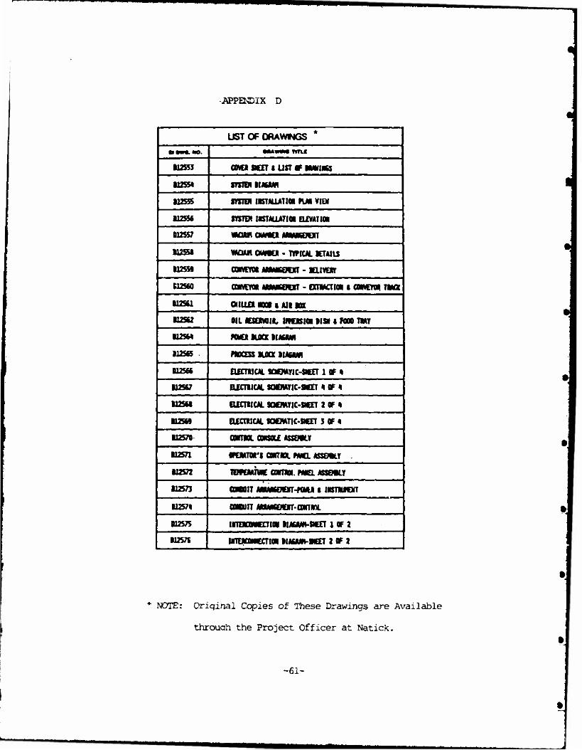
APPENDIX D
UST OF DRAWWGS *
t$mm%.mo. IM—I «TU
112553 cova sen i usT tr MANIACS
B1255* SYSTEH IIACAM
U2S55 mroi IBTALLATIOI KM VIEM
B12SS6 STSTDI IKTALUTlOi ELEVATION
D12S57 «aw atAftat AMMMOOT
012551 wann awtu - TYPICAL BCTAILS
B1255B aftVCffft «MM60CHT - BELWEIf
612560 COWEYOI MAMKOOT - EXTIACTiai C COBWETQ« TMCX
B12S61 OILLO K» | All m
112542 OIL BttONOiL tftUSIOI1!» 1 N0O TMT
B12S6* WO BLOCK HAMM
B12S65 PBOCESS BLOCK BIAiBAJI
B12566 ELECTUCAL SOtMTIC-SKET 1 OF 4
M2567 ELECTUCAL MOWIC-SÄET 1 OF 4
112561 ELECTUCAL SCMEMTIC-SKET 2 OF 6
112569 ELECTUCAL SQCMTIC-9CET S OF 4
112570 CQKTBOL CONSOLE ASSOVLY
112571 OFOäTOA'S CONTNOL FANOL ASSEHLT
•12572 TDTOWTWE CDBTBOI. PMEL ASSEMBLY
112573 CONBOIT ABBAB600T-WJM l INSTBUJCiT
U2574 CONDUIT AttAMOiVT-CIMTIIX.
B12575 maamaim UASA/N-SHEET i OF 2
112576 iiTEBcatcaiai UA6AAV»CET 2 OF 2
NOTE: Original Copies of These Drawings are Available
throuqh the Project Officer at Natick.
-61-
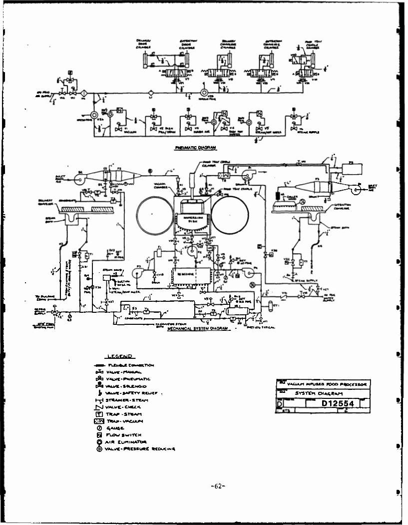
niMMmi
fWEUMATC OAQRAM
* i if ~, 1 n
2S-^r
«W MHPl
^$~*
^ >W* (.MM. V»t«(»»/tO«» KM»«.
r -sHo—^- i.kitk «_ L.
4- c-^—^Sr^-^tev MECHANISM. SYSTEM PAQBAM 'WBlH-tWiMk
LSftCMB
A VALVC-PMCUTUtTtC
Ji \Äfcvc-»ArcTv neuer .
H^ 3T*AJ*C»-ST*AM fVj VALwC-CMttK.
E) TIUf-STtAn
g ru)w SWITCH
© At« CUMIMATO«
ra* v«£Ukrt »*rus*.o rooo P«ocesso«
SYSTCH D<AQ*Af-i
D12554 r
-62-
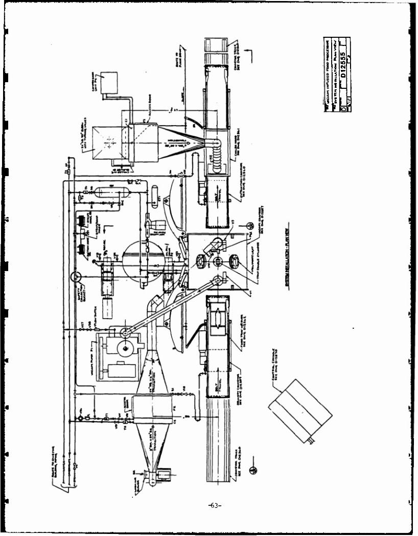
Lfc
10
M
1 - i
a
-63-

8- o
it
Ufa-
-64-
i
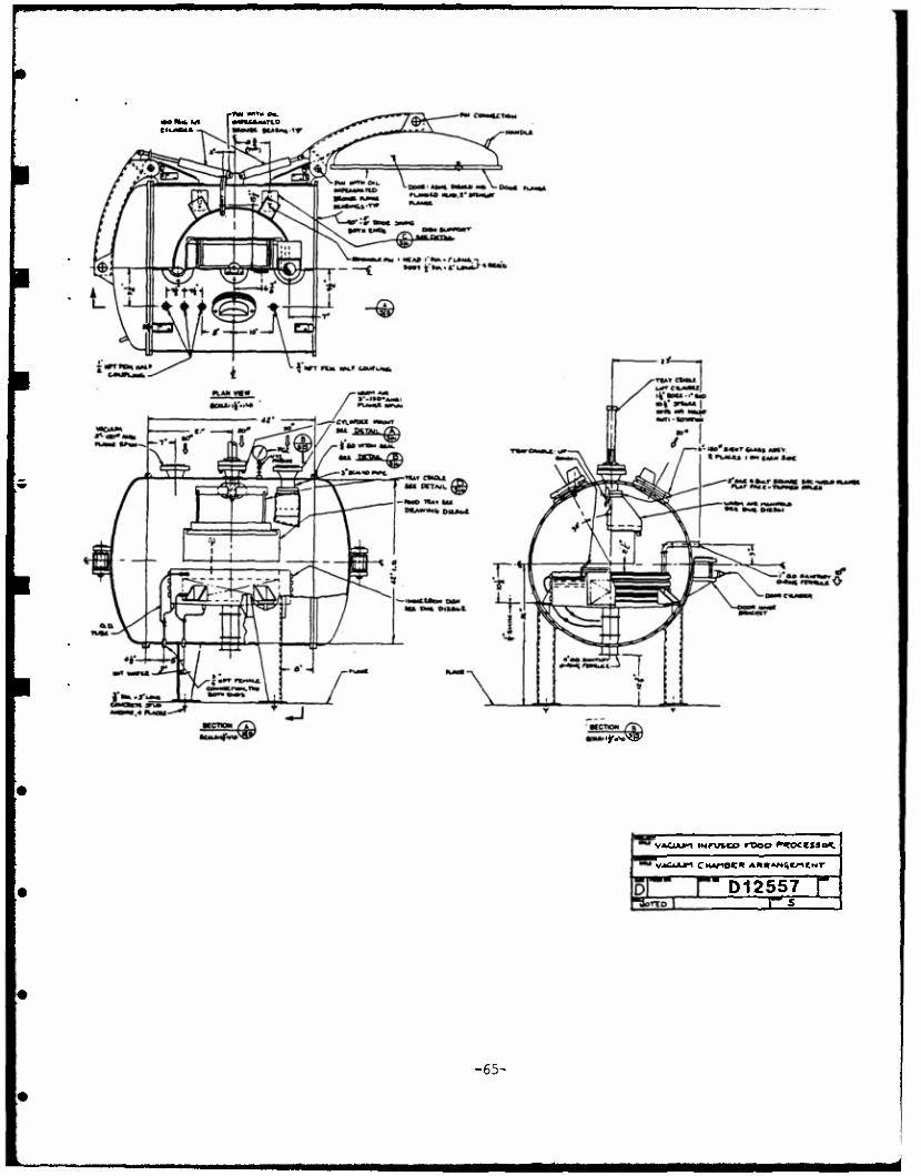
1*-^
VACUUM iNPVAco rooo ^*occsso*.
"D12557 f
-65-
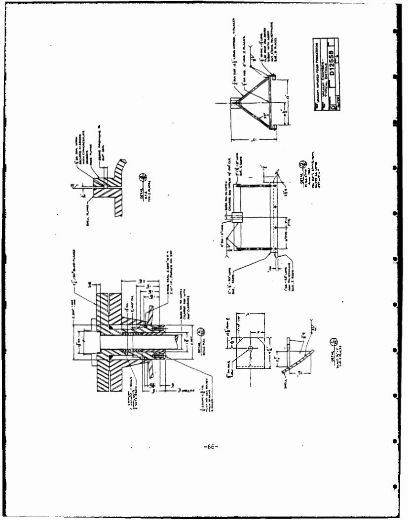
Ml. ■"ill
•— .4
s f—.»-*"
1 / \ ,! r
?r jit I di
-66-
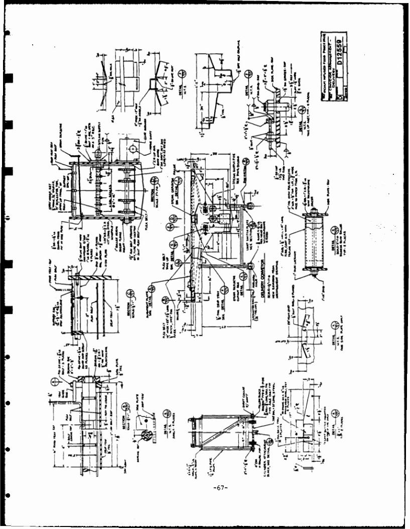
-67-
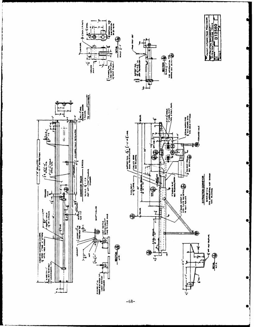
»«—H
IV 2 LJ rp. I jflF
a 4i i
1? ST
" !;
C4
Q |Q!5
-68-
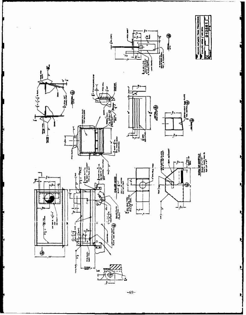
a
'///X i AW h
-69-
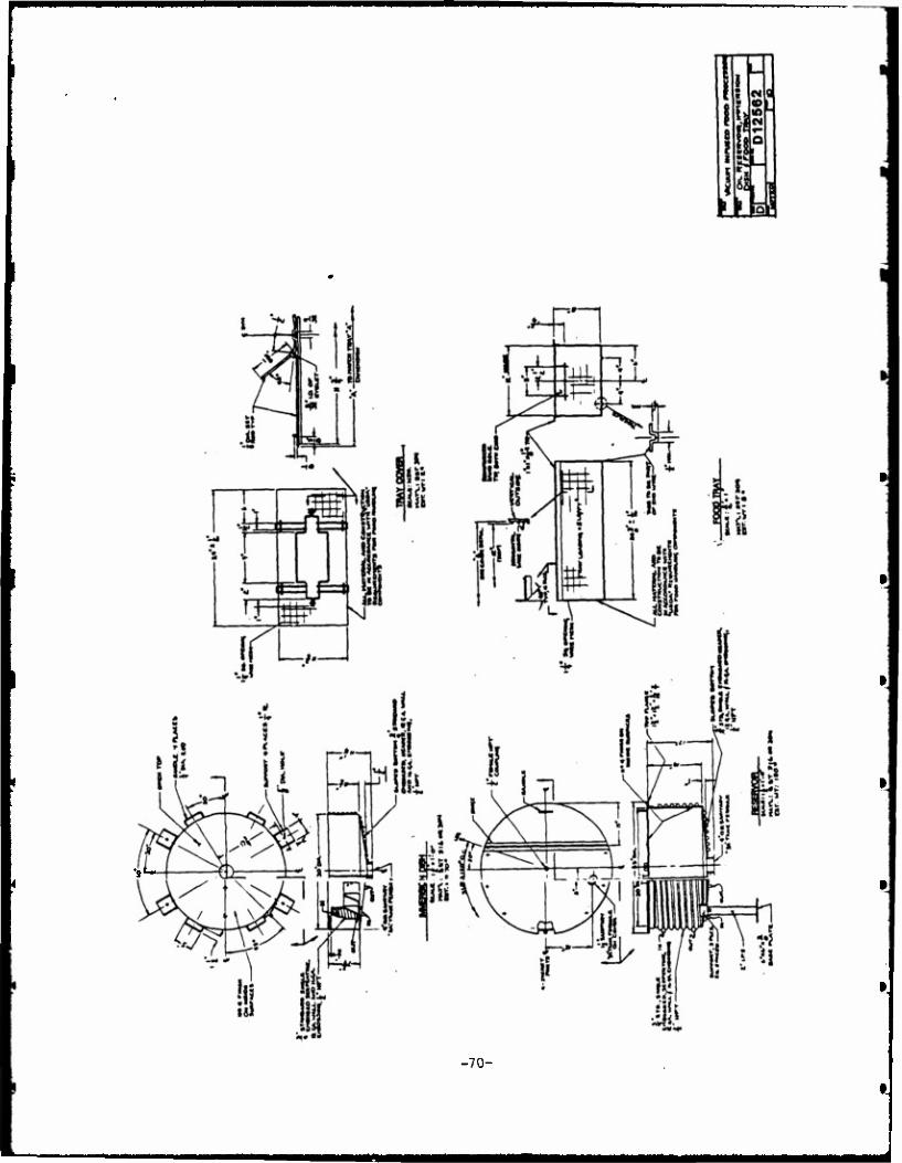
•,l*
-70-
*m
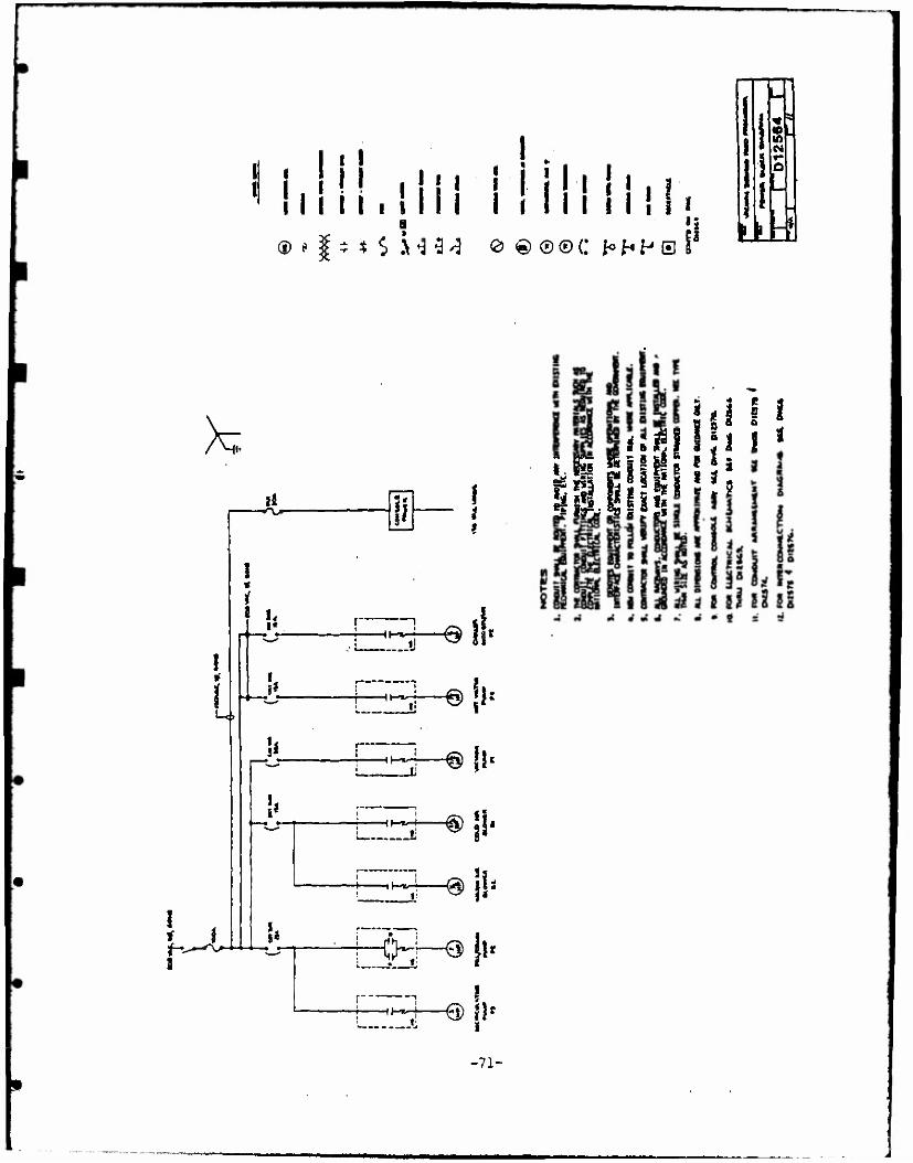
^■w
I 1' i M ill' 11 11 . I
I
II in i ill. ®*I-*$.\'33'J e©®®CM«PS
■r-
h
IH* 3-«««
Li?i \i SlJliil
^ * ä 1 5 2
1 i | 5 Ig 1 s!
i i
Ui
HHr
lh*-
!
It
Hl-*- i Ij
H It-*-
i»
h^ll-
<H—9 fi< i
HHx~ •6) «■ i
-71-
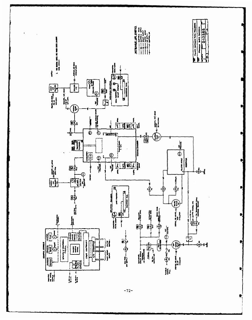
ä 1 B
I. i
»lt.« Uli!
i! I 1
il 7
M' T it! fr* 1*5
£
KB j a
BÖ
1 11
?l
ii. in; ifj <|)t
ls;
—©
4U I TSISO|s
e\ H
i!
T —*—
IA
in • il in -
o
LL
•ml!
r
Hl ij
rCBj i ■ *—-
\ «
ll
ih ;i
3
11
n^t^H
-72-
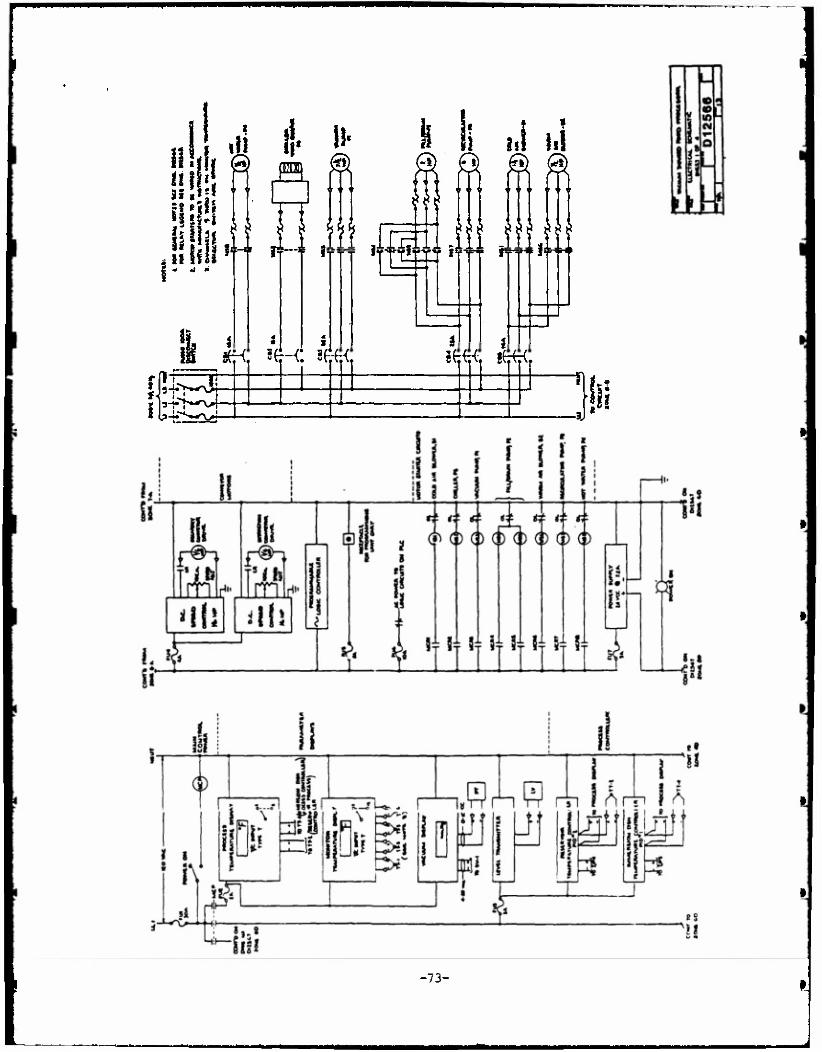
^M^^M
i i * S '( @ pq &fi S| '' Y Y 2 * I ■ __^^_
liigl*
!M! 11' Tl lilhi j? ■■ Sell !«w' f3> 58 If II M ST
li sJ hi
?£._/• SL*.£ y
77?
«H ae-c !p TT
3T'
f<
111111 1111,1
??? ??? ???
i 8«tf iFfcC
-73-
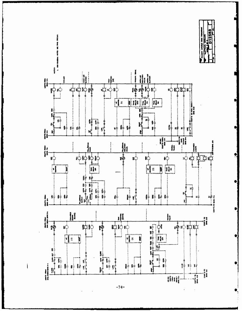
»I«
tiki
-74-
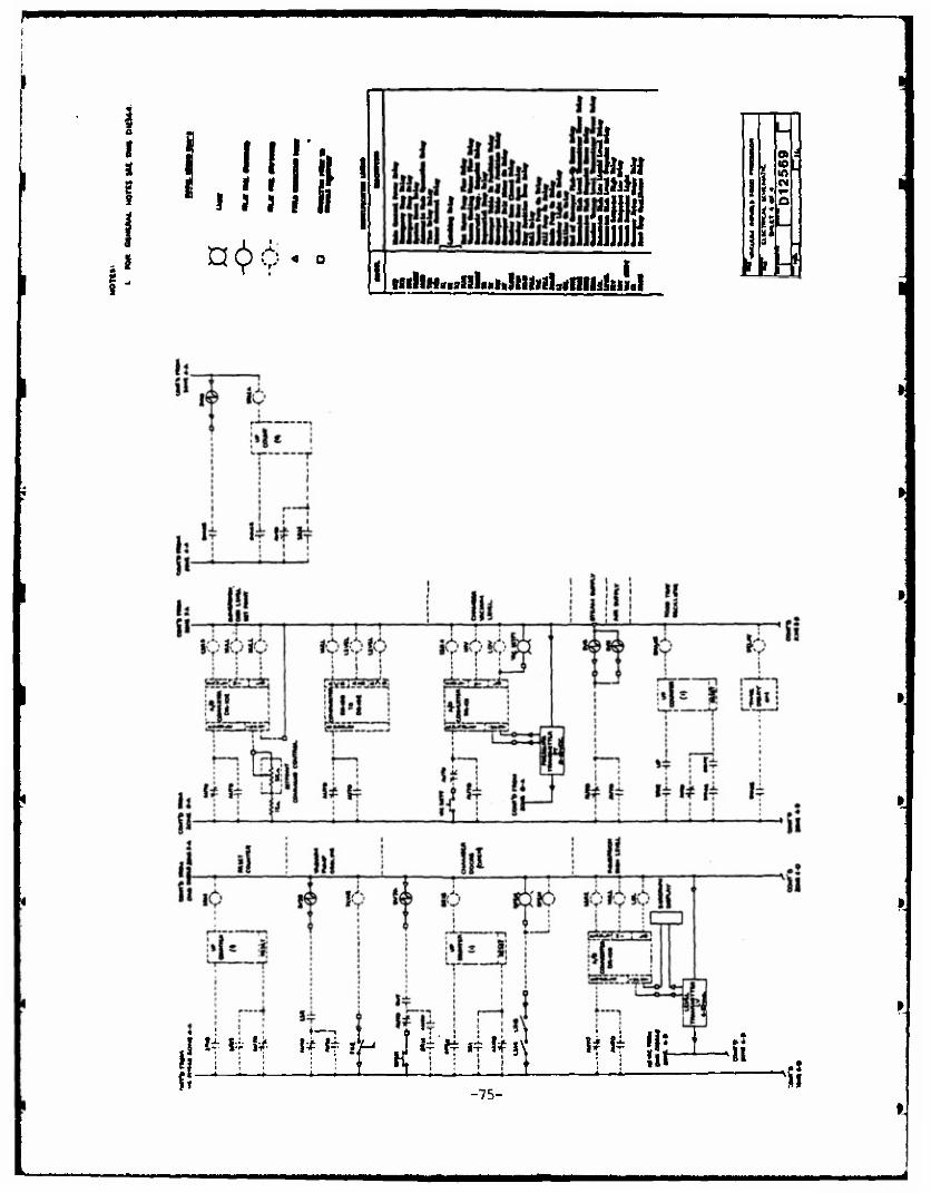
\
Mi 4 • if n<>6 4 a
1 U ttihn**8nUuHUiuih*mulmd
H
(0 m
i
I I* Liillia •ft ÜM-Ü -75-
ti
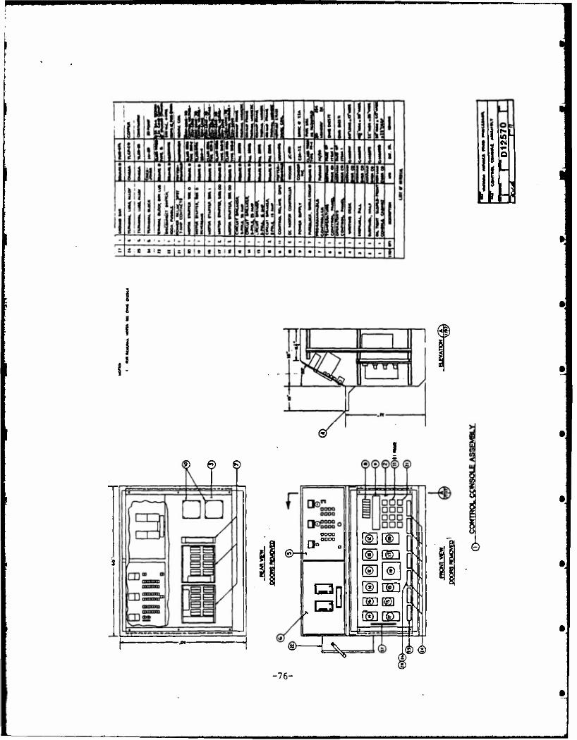
CM
I
i a
it
£) © ©
@- «
D
<g>" ^
®l l©l ® dlcsa
GECED
NT
S
ü
0
-76-
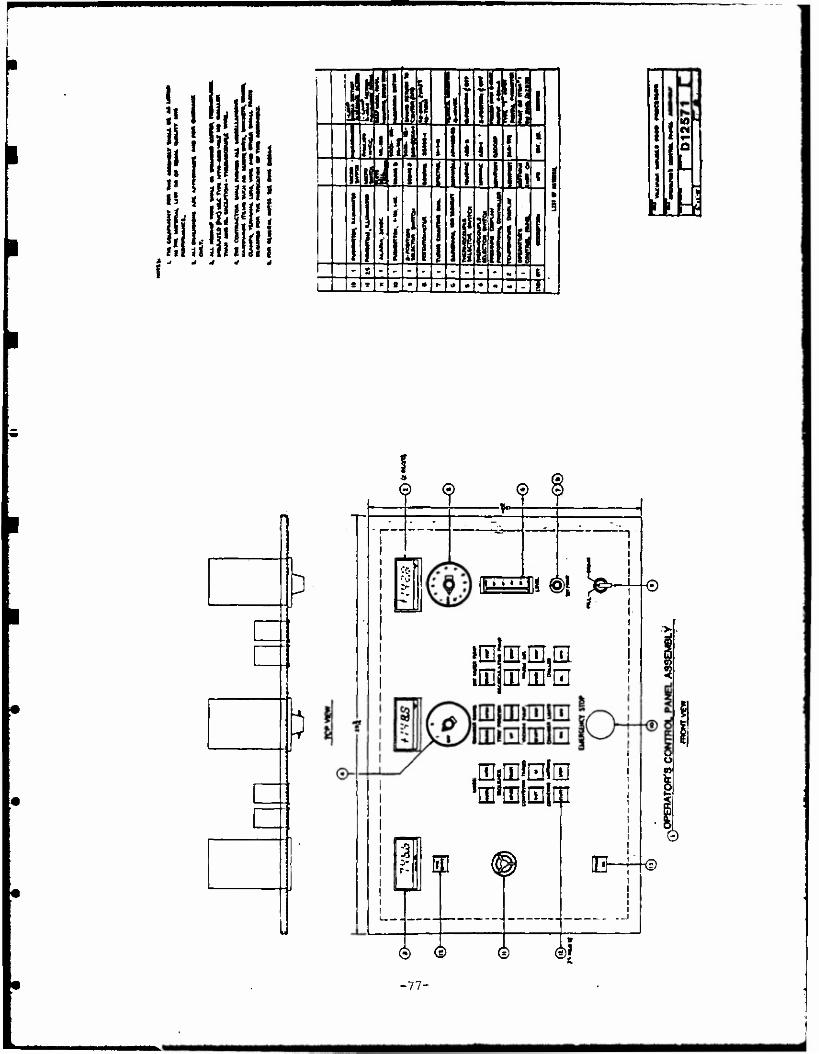
I I '4. ■Hi
2 furl i
-> -I 4
w
li h
II
li1 ii 1$
i in
i Ik
3
3
1 V'
•v, iiii *€>! >j 1*4-«
tit
im mwm
ffl'mlHliii
m
® ®
-77-
© ®|
©
©
■a
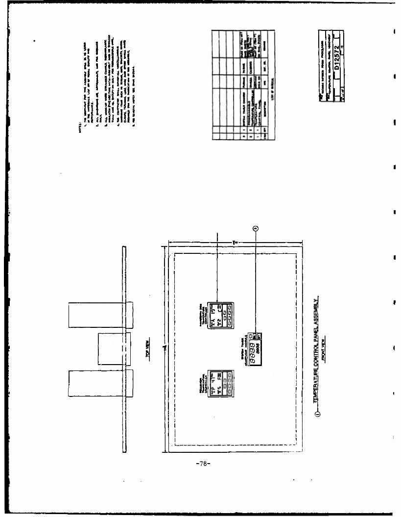
V i !
V
: |i| J [in
ifi iflli iiiUt
CM r- C4
©
li
i~
•l«.
< Ai
öGB 55! CD! CD CD
-78-
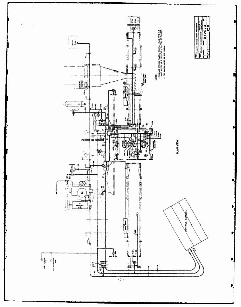
-79-
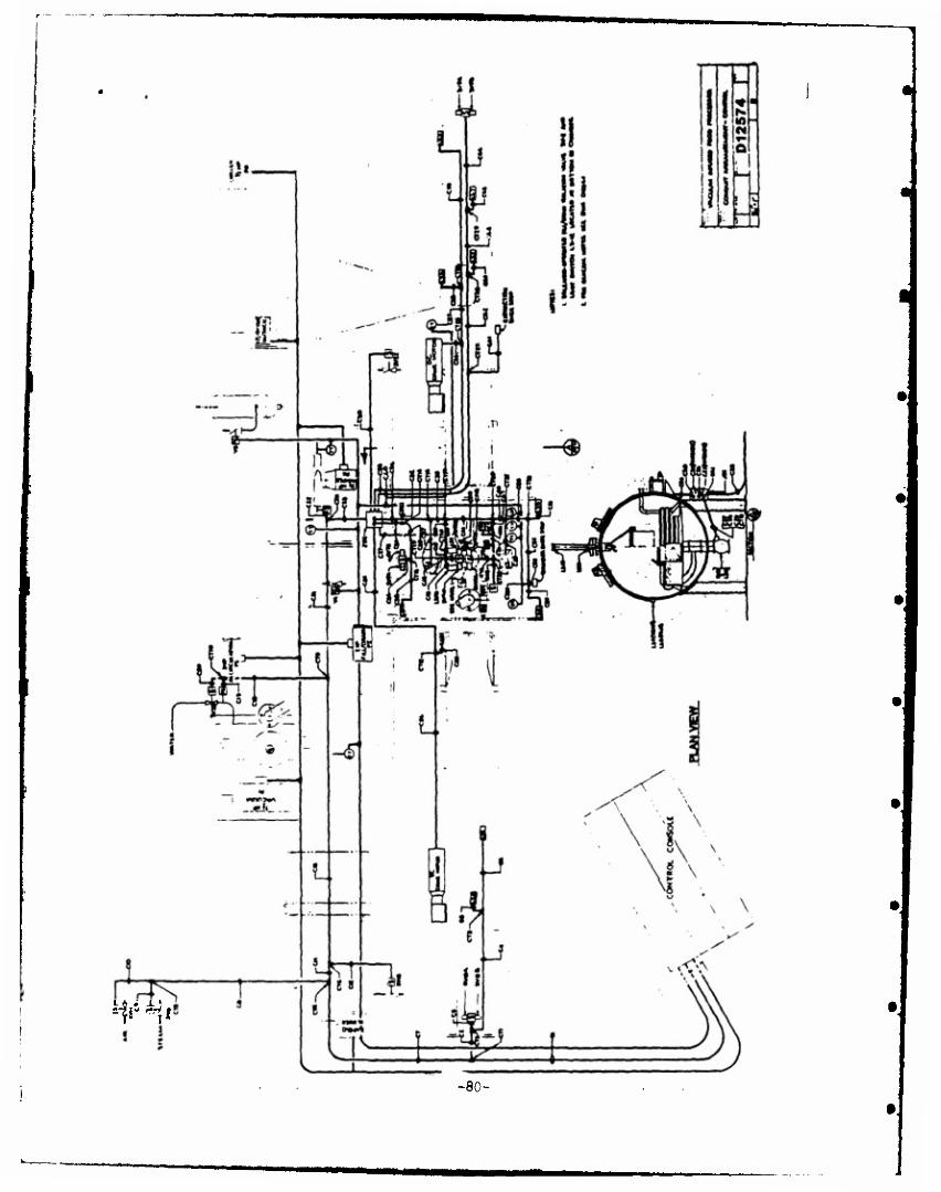
ty*ii
-80-
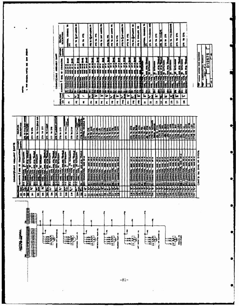
{'
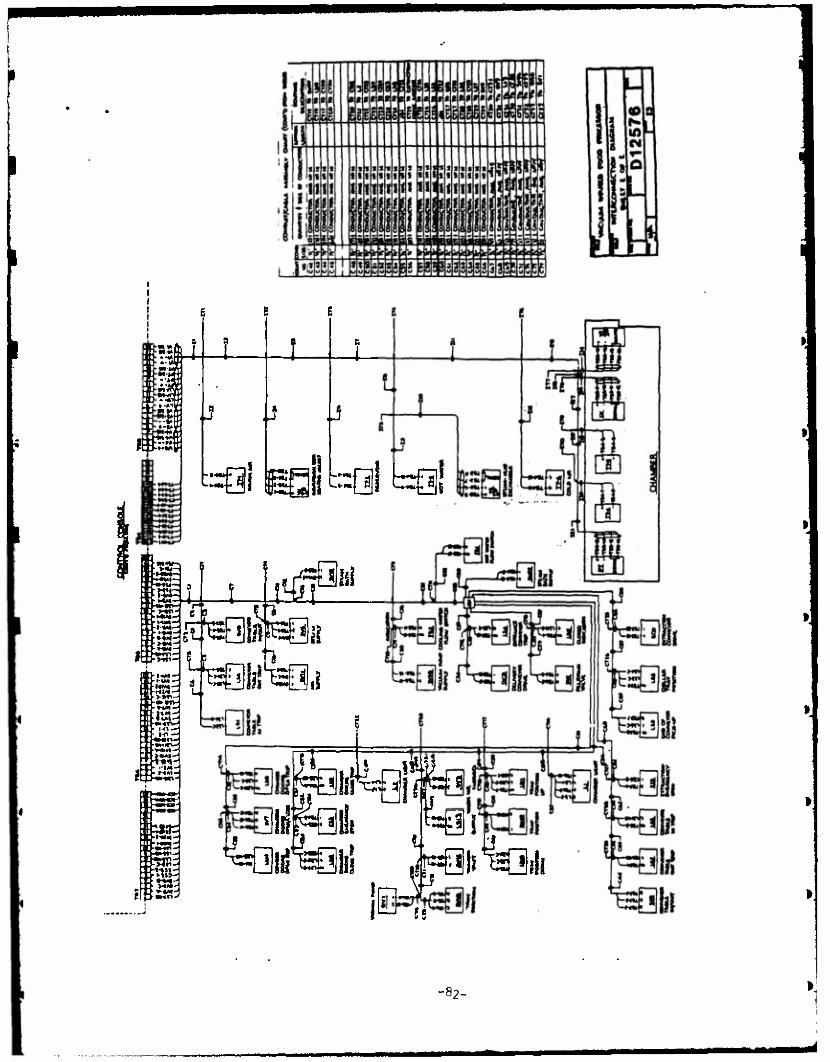
=ai m(\
J
..«=15
J
:::Qj rQI
«BE ■HW-
■ »4M
-l-«M-H
zB
•-IM-
HIM- ■>»«V •■»tH
T . UM-
MM
t 3 i itrfp"
Siiiglf^
H
-82-