Design Of A Low-Impact Wastewater Collection And Treatment ...
65
Santa Clara University Scholar Commons Civil Engineering Senior eses Engineering Senior eses 6-10-2014 Design Of A Low-Impact Wastewater Collection And Treatment System For Siladen Island In Indonesia Kyle Astill Santa Clara Univeristy Charles Rymer Santa Clara Univeristy Joseph Sarmiento Santa Clara Univeristy Follow this and additional works at: hps://scholarcommons.scu.edu/ceng_senior Part of the Civil and Environmental Engineering Commons is esis is brought to you for free and open access by the Engineering Senior eses at Scholar Commons. It has been accepted for inclusion in Civil Engineering Senior eses by an authorized administrator of Scholar Commons. For more information, please contact [email protected]. Recommended Citation Astill, Kyle; Rymer, Charles; and Sarmiento, Joseph, "Design Of A Low-Impact Wastewater Collection And Treatment System For Siladen Island In Indonesia" (2014). Civil Engineering Senior eses. 18. hps://scholarcommons.scu.edu/ceng_senior/18
Transcript of Design Of A Low-Impact Wastewater Collection And Treatment ...

Santa Clara UniversityScholar Commons
Civil Engineering Senior Theses Engineering Senior Theses
6-10-2014
Design Of A Low-Impact Wastewater CollectionAnd Treatment System For Siladen Island InIndonesiaKyle AstillSanta Clara Univeristy
Charles RymerSanta Clara Univeristy
Joseph SarmientoSanta Clara Univeristy
Follow this and additional works at: https://scholarcommons.scu.edu/ceng_senior
Part of the Civil and Environmental Engineering Commons
This Thesis is brought to you for free and open access by the Engineering Senior Theses at Scholar Commons. It has been accepted for inclusion in CivilEngineering Senior Theses by an authorized administrator of Scholar Commons. For more information, please contact [email protected].
Recommended CitationAstill, Kyle; Rymer, Charles; and Sarmiento, Joseph, "Design Of A Low-Impact Wastewater Collection And Treatment System ForSiladen Island In Indonesia" (2014). Civil Engineering Senior Theses. 18.https://scholarcommons.scu.edu/ceng_senior/18
ii
TITLE PAGE
DESIGN OF A LOW-IMPACT WASTEWATER COLLECTION AND TREATMENT
SYSTEM FOR SILADEN ISLAND IN INDONESIA
by
Kyle Astill
Charles Rymer
&
Joseph Sarmiento
SENIOR DESIGN PROJECT REPORT
submitted to
the Department of Civil Engineering
of
SANTA CLARA UNIVERSITY
in partial fulfillment of the requirements
for the degree of
Bachelor of Science in Civil Engineering
Santa Clara, California
Spring 2014

iii
ACKNOWLEDGEMENTS
We would like to thank our project advisor Dr. Steven Chiesa, whose valuable guidance and
advice has been essential to the design and learning process of this team.
We would also like to thank Professor Loring Pfeiffer, for her valuable advice in assembling a
successful thesis and presentation.
And Sarah Westropp at Bobocha Siladen resort, the design team’s primary island contact, whose
on-site information about Pulau Siladen has been fundamental to the design of this system.
iv
DESIGN OF A LOW-IMPACT WASTEWATER COLLECTION AND TREATMENT
SYSTEM FOR SILADEN ISLAND IN INDONESIA
Kyle Astill, Charles Rymer, and Joseph Sarmiento
Department of Civil Engineering
Santa Clara University, Spring 2014
ABSTRACT
Untreated wastewater is highly destructive to human health and the environment.
Choosing an island location, Pulau Siladen, which has no wastewater treatment solution, the
design team embarked upon designing a centralized collection and treatment system to treat the
island population’s wastewater, in the interests of preserving human health and the sensitive
coral reefs surrounding the island. This system features a gravity sewer system, flow
equalization, sequencing batch reactor, sand filter and disinfection as part of the treatment
process. This project will emphasize the reduction in use of highly specialized and manufactured
components, in an effort to minimize the economic, environmental and societal impacts of
implementing this project. Due to the large scale of this project, it is estimated that 1 more year
of work by a senior design project team will be necessary to see this design in a state ready to be
implemented on the island.

v
TABLE OF CONTENTS
CERTIFICATE OF APPROVAL .................................................................................................... i
TITLE PAGE .................................................................................................................................. ii
ACKNOWLEDGEMENTS ........................................................................................................... iii
ABSTRACT ................................................................................................................................... iv
TABLE OF FIGURES .................................................................................................................. vii
INTRODUCTION .............................................................................................................. 1
SITE LOCATION ........................................................................................................................... 5
Coral Reefs .................................................................................................................................. 5
Pulau Siladen ............................................................................................................................... 9
DESIGN PHILOSOPHY .............................................................................................................. 15
Potential Solutions..................................................................................................................... 15
Logic in Selecting a Solution .................................................................................................... 18
Chosen Solution Strategy .......................................................................................................... 19
Project Design Tasks ................................................................................................................. 21
DESIGN CRITERIA .................................................................................................................... 23
Environmental Discharge Standards ......................................................................................... 23
Determination of Average Daily Flow ...................................................................................... 25
SYSTEM COMPONENTS AND DESIGN ................................................................................. 27
Sewer Network Design.............................................................................................................. 27
Flow Equalization Sump ........................................................................................................... 31
Treatment System Components ................................................................................................ 35
Sequencing Batch Reactor ........................................................................................................ 38
Sequencing Batch Reactor Design Criteria ............................................................................... 41
AquaCAM-D ............................................................................................................................. 42
Tentative SBR Daily Timing Schedule ..................................................................................... 44
Slow Trickle Sand Filters .......................................................................................................... 46
Sludge Drying Bed .................................................................................................................... 47
Disinfection ............................................................................................................................... 48
ENGINEER’S OPINION OF MOST PROBABLE COST .......................................................... 50

vi
OTHER ISSUES ........................................................................................................................... 52
Non-Technical Issues ................................................................................................................ 52
Ethical Issues ............................................................................................................................. 53
Conclusion ................................................................................................................................. 54
WORKS CITED ........................................................................................................................... 55
vii
TABLE OF FIGURES
Figure 1: Slum conditions result from poor sanitation. ................................................................. 1 Figure 2: Vibrant coral reefs are beautiful yet endangered. .......................................................... 2
Figure 3: Disease wreaks havoc on coral ecosystems. .................................................................. 3 Figure 4: Rich coral reef ecosystems in Indonesia. ....................................................................... 6 Figure 5: Pulau Siladen surrounded by barrier reef. Resorts located on west coast and local
village to the south. ......................................................................................................................... 7 Figure 6: Siladen Island (A) with respect to the Southeast Asia region ........................................ 8
Figure 7: Pulau Siladen (A) and other similar Manado Islands. .................................................... 8 Figure 8: Panorama of the island. .................................................................................................. 9 Figure 9: One resort, view from water. .......................................................................................... 9 Figure 10: Higher quality concrete construction for some locals. Main road is a footpath as there
are no vehicles on the island. ........................................................................................................ 10 Figure 11: Resort restaurant building retains traditional Indonesian architecture while being of
adequate construction on a concrete slab. ..................................................................................... 11 Figure 12: One resort is capable of maintaining a luxurious pool. .............................................. 11
Figure 13: Crystal clear waters off the northern point. ................................................................ 12 Figure 14: Beautiful reef formations and water, worthy of protection. ....................................... 12 Figure 15: Conceptual Drawing of a Traditional Septic Tank System. ....................................... 15
Figure 16: Municipal-Type Wastewater Treatment Facility. ...................................................... 16 Figure 17: Common package treatment plant layout. .................................................................. 17
Figure 18: Screen capture of generated 3D model. ..................................................................... 28 Figure 19: Sewer system design schematic. ................................................................................ 29 Figure 20: Main pipeline profile, 0 Station represents the system’s northernmost point. ........... 30
Figure 21: Daily flow trend. ........................................................................................................ 32
Figure 22: Sump Section and Plan view. ..................................................................................... 33 Figure 23: Pump performance curve for Model 915. Operating in efficient region. ................... 34 Figure 24: Conceptual flowchart of treatment process. ............................................................... 36
Figure 25: Proposed site location, at low point of sewer network. .............................................. 37 Figure 26: Proposed system layout. ............................................................................................. 37
Figure 27: Flowchart illustrating each SBR phase. ..................................................................... 38 Figure 28: Similar concrete basin with AquaCAM-D unit. ......................................................... 40
Figure 29: Tipton TEII model as delivered to client. (Tipton Environmental Inc.) .................... 49

1
INTRODUCTION
Proper sanitation is a basic human need. “It is a crucial stepping stone to better health,”
and vital in ensuring a decent quality of living and preventing poverty. (UNICEF) “2.5 billion
people still lack access to improved sanitation, including 1.2 billion who have no facilities at
all… 1.5 million children die a year, succumbing to diarrheal diseases… The message is clear:
We need to greatly accelerate progress in sanitation, particularly in sub-Saharan Africa and
Southern Asia.” (UNICEF) Data shows that “people are choosing to move up the ‘sanitation
ladder’, abandoning open defecation and revealing a demand for sanitation facilities,” (UNICEF)
illuminating a reason for this project’s conception and completion.
Figure 1: Slum conditions result from poor sanitation.
2
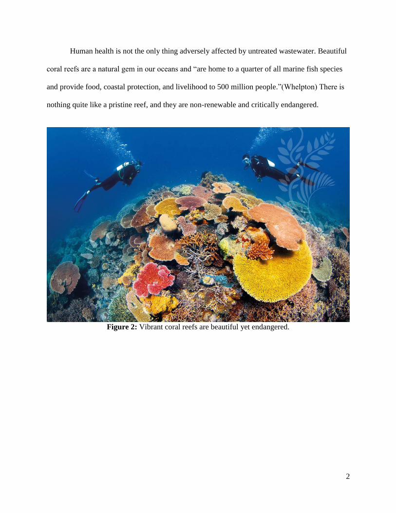
Human health is not the only thing adversely affected by untreated wastewater. Beautiful
coral reefs are a natural gem in our oceans and “are home to a quarter of all marine fish species
and provide food, coastal protection, and livelihood to 500 million people.”(Whelpton) There is
nothing quite like a pristine reef, and they are non-renewable and critically endangered.
Figure 2: Vibrant coral reefs are beautiful yet endangered.
3
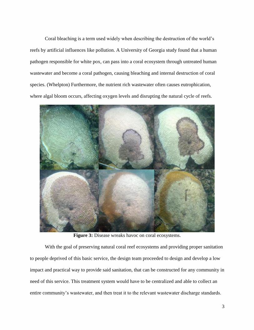
Coral bleaching is a term used widely when describing the destruction of the world’s
reefs by artificial influences like pollution. A University of Georgia study found that a human
pathogen responsible for white pox, can pass into a coral ecosystem through untreated human
wastewater and become a coral pathogen, causing bleaching and internal destruction of coral
species. (Whelpton) Furthermore, the nutrient rich wastewater often causes eutrophication,
where algal bloom occurs, affecting oxygen levels and disrupting the natural cycle of reefs.
Figure 3: Disease wreaks havoc on coral ecosystems.
With the goal of preserving natural coral reef ecosystems and providing proper sanitation
to people deprived of this basic service, the design team proceeded to design and develop a low
impact and practical way to provide said sanitation, that can be constructed for any community in
need of this service. This treatment system would have to be centralized and able to collect an
entire community’s wastewater, and then treat it to the relevant wastewater discharge standards.

4
The system would have to be first developed to fully provide sanitation for a single location, as a
form of testing for treatment effectiveness of the system. If successful, this system would be
scaled and adapted to suit other communities similar to the initial site location. This initial
system would have to be scalable and suitable for a small community, as it is desired to provide
proper sanitation to people far and wide, not just those who happen to be living in larger cities
where a municipal type treatment system is most suitable. Because economic power and
education between first world and third world counties is disparate, this system would have to
have a minimal economic and environment footprint, as well as being easily operable and
maintained by unskilled laborers.

5
SITE LOCATION
Coral Reefs
The world’s richest coral reefs are scattered far and few between amongst few locations,
including Australia, The Mediterranean oceans, many islands in the Pacific and Atlantic oceans,
and all of the countries sharing the Southeast Asia sea. Amongst Scuba diving
tourists/professionals, and those in the industry of marine resources conservation, the world’s
most beautiful but also most endangered reefs are situated in Indonesia. A report by Worldwatch
Institute, a large environmental research organization that works closely with the United States
Government’s policymakers stated:
“If you're going to talk about coral, Indonesia is the place to be. With the world's richest
and most extensive coral reefs, Indonesia probably harbors more underwater species than any
other nation. This archipelago of 17,000 islands is also where the stakes are highest for ocean
conservation: more people live closer to reefs here, in the fourth-most populous nation on Earth,
than anywhere else... The devastating implications of El Niño and climate change for corals, and
ways to stop reef-killing fishing practices and the spread of coral disease-are tremendously
important for this nation of coastal dwellers and fish eaters.” (Worldwatch)
6
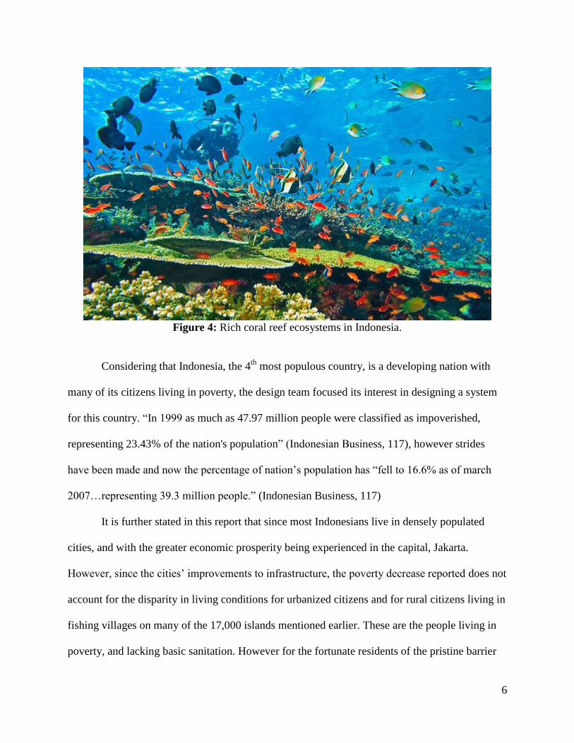
Figure 4: Rich coral reef ecosystems in Indonesia.
Considering that Indonesia, the 4th
most populous country, is a developing nation with
many of its citizens living in poverty, the design team focused its interest in designing a system
for this country. “In 1999 as much as 47.97 million people were classified as impoverished,
representing 23.43% of the nation's population” (Indonesian Business, 117), however strides
have been made and now the percentage of nation’s population has “fell to 16.6% as of march
2007…representing 39.3 million people.” (Indonesian Business, 117)
It is further stated in this report that since most Indonesians live in densely populated
cities, and with the greater economic prosperity being experienced in the capital, Jakarta.
However, since the cities’ improvements to infrastructure, the poverty decrease reported does not
account for the disparity in living conditions for urbanized citizens and for rural citizens living in
fishing villages on many of the 17,000 islands mentioned earlier. These are the people living in
poverty, and lacking basic sanitation. However for the fortunate residents of the pristine barrier
7
reef islands, the locals are assisted above the poverty line by the money offered by tourism from
the thousands of Scuba diving enthusiasts eager to experience some of the world’s most beautiful
marine wildlife.
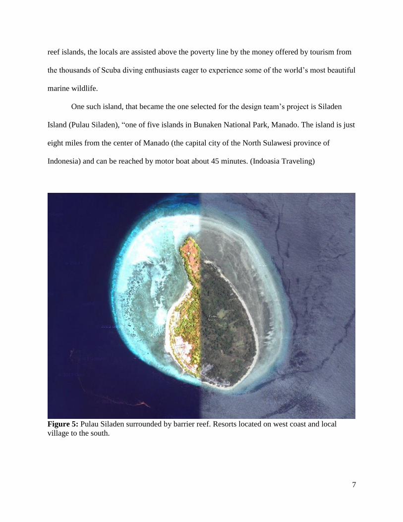
One such island, that became the one selected for the design team’s project is Siladen
Island (Pulau Siladen), “one of five islands in Bunaken National Park, Manado. The island is just
eight miles from the center of Manado (the capital city of the North Sulawesi province of
Indonesia) and can be reached by motor boat about 45 minutes. (Indoasia Traveling)
Figure 5: Pulau Siladen surrounded by barrier reef. Resorts located on west coast and local
village to the south.
8
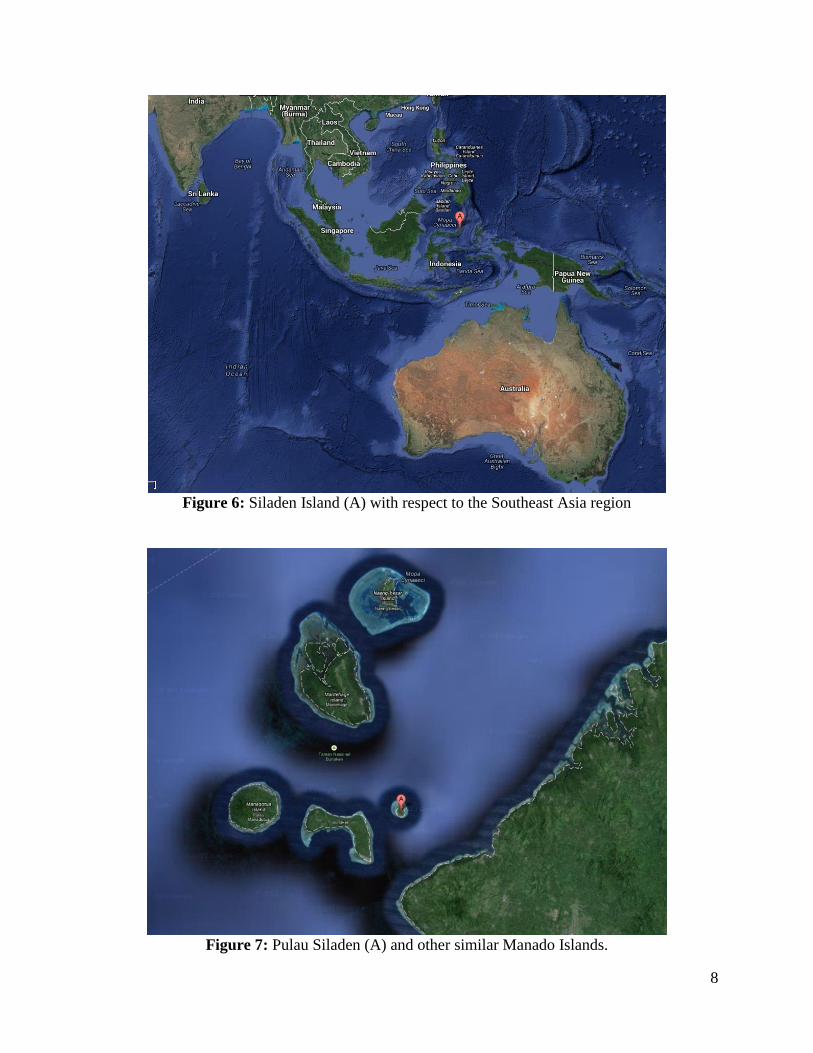
Figure 6: Siladen Island (A) with respect to the Southeast Asia region
Figure 7: Pulau Siladen (A) and other similar Manado Islands.
9
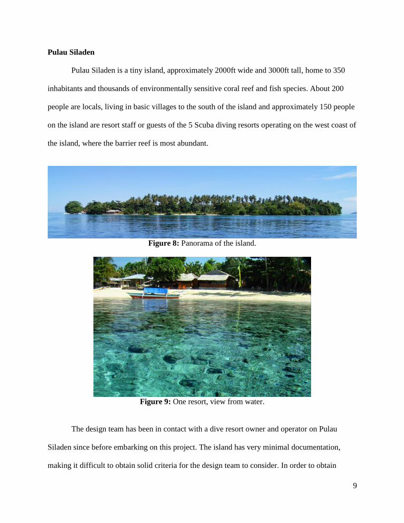
Pulau Siladen
Pulau Siladen is a tiny island, approximately 2000ft wide and 3000ft tall, home to 350
inhabitants and thousands of environmentally sensitive coral reef and fish species. About 200
people are locals, living in basic villages to the south of the island and approximately 150 people
on the island are resort staff or guests of the 5 Scuba diving resorts operating on the west coast of
the island, where the barrier reef is most abundant.
Figure 8: Panorama of the island.
Figure 9: One resort, view from water.
The design team has been in contact with a dive resort owner and operator on Pulau
Siladen since before embarking on this project. The island has very minimal documentation,
making it difficult to obtain solid criteria for the design team to consider. In order to obtain
10
sufficient data for the system design, the design team to relied on specific and quality questions
and answers with the island contact, as well as using Google earth and manipulating data with
various engineering programs at the team’s disposal.
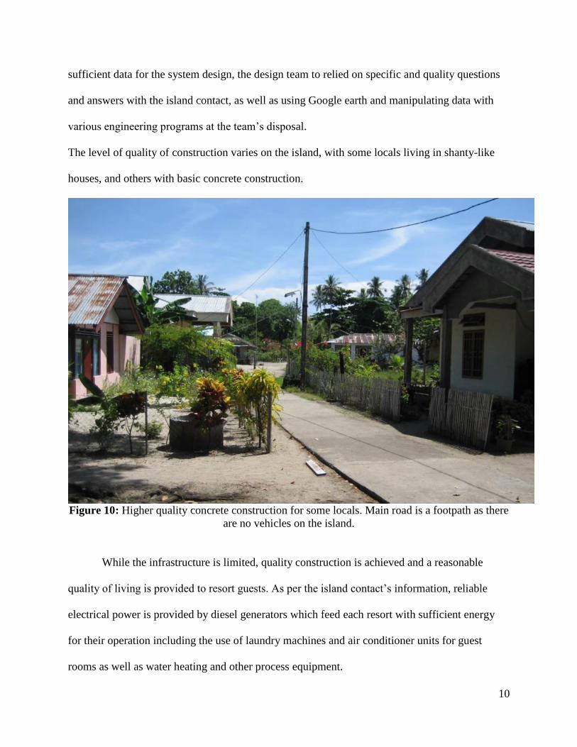
The level of quality of construction varies on the island, with some locals living in shanty-like
houses, and others with basic concrete construction.
Figure 10: Higher quality concrete construction for some locals. Main road is a footpath as there
are no vehicles on the island.
While the infrastructure is limited, quality construction is achieved and a reasonable
quality of living is provided to resort guests. As per the island contact’s information, reliable
electrical power is provided by diesel generators which feed each resort with sufficient energy
for their operation including the use of laundry machines and air conditioner units for guest
rooms as well as water heating and other process equipment.

11
Figure 11: Resort restaurant building retains traditional Indonesian architecture while being of
adequate construction on a concrete slab.
Figure 12: One resort is capable of maintaining a luxurious pool.
12
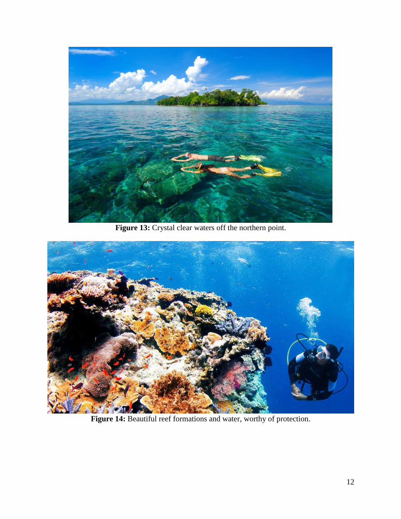
Figure 13: Crystal clear waters off the northern point.
Figure 14: Beautiful reef formations and water, worthy of protection.
13
It is clear that there is much to be valued on Pulau Siladen. Resort owners have invested
much in infrastructure, to build and operate such quality resorts in this pristine remote island.
There is much at stake for the resort operators economically, for if this island’s corals reefs are
severely degraded, or human health is known to be at risk on this island, resort operators and
locals alike would no longer reap the benefits of the steady income from tourism here, hence it is
all parties’ best interests to protect and preserve Pulau Siladen. However, for all the beauty and
investment in infrastructure on the island, there is still currently no method of providing proper
sanitation whatsoever on the island.
According to the island contact, currently in place are individual small septic pits situated
under each lavatory. This is a primitive ancient Dutch method where layers of dirt, coral and
natural fibers filter the effluent produced by each toilet, collecting the sludge in the membranes
and the mildly filtered water passes below, permeating into the soil. With this method, the
excreta is not distanced sufficiently from humans and manual labor is required to scrape the toxic
sludge from the membranes. Due to the poor level of treatment and the residual sludge remaining
in the ground, this does not classify as an adequate and sustainable practice for providing proper
sanitation. This potentially leaves the local environment susceptible to damage caused by
wastewater contamination.
In an effort to be sustainable, some resort operators state on their websites that kitchen
sink/food preparation water is collected and transported by boat to be dumped into the ocean.
(Siladen) Considering that this design team’s Wastewater Treatment (WWT) system will treat all
forms of wastewater, this laborious collection and discharge method will be eliminated, helping
offset the cost in the implementation of the designed system.
14
It is reported that resort owners are concerned about the purity of the groundwater and
possible sludge runoff issues due to prolonged use of an inadequate treatment method. It is also
reported that fresh water is scarce and that all island inhabitants, including guests are encouraged
to use fresh water very sparingly. Rainwater and groundwater are the two sources of potable
water. It would be catastrophic if the aquifer became contaminated, forcing wells to be
decommissioned, and requiring the difficult task of decontaminating it.
According to World Weather Online, this region is susceptible to heavy storm downpour
due to its tropical climate. (WWO) This large volume of rainfall causes runoff into the ocean to
be a regular occurrence. With the soil being laden with effluent, paired with large amounts of
runoff, it is inevitable that contaminants will make it into the ocean, and the contaminated soil
would certainly affect land based life in the long run.
The Siladen resort on the island has a mission “to preserve the natural habitat and assist
the local villagers.”(Siladen) It is the design team’s goal in assisting island inhabitants in
fulfilling this mission, therefore validating this project as having community need, and
additionally satisfying a commercial need, by preserving the assets that generate economic
prosperity on the island. Primarily, the goal is to preserve the natural habitat and safeguard
human health with a long term, cost effective and sustainable waste solution. It would be a wise
investment for the primary stakeholders on the island.
15
DESIGN PHILOSOPHY
Potential Solutions
During the design process, four potential solutions to providing Wastewater Treatment
for Pulau Siladen were identified.
Septic tank
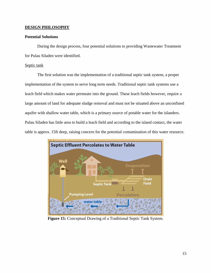
The first solution was the implementation of a traditional septic tank system, a proper
implementation of the system to serve long term needs. Traditional septic tank systems use a
leach field which makes water permeate into the ground. These leach fields however, require a
large amount of land for adequate sludge removal and must not be situated above an unconfined
aquifer with shallow water table, which is a primary source of potable water for the islanders.
Pulau Siladen has little area to build a leach field and according to the island contact, the water
table is approx. 15ft deep, raising concern for the potential contamination of this water resource.
Figure 15: Conceptual Drawing of a Traditional Septic Tank System.
16
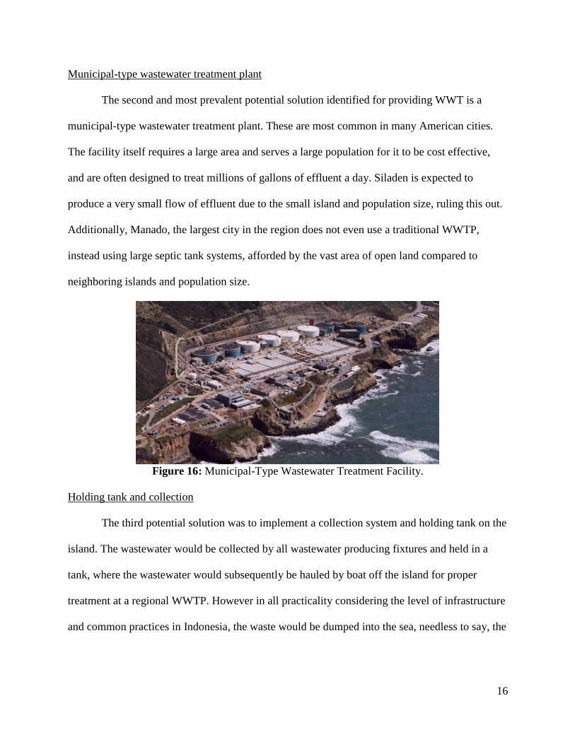
Municipal-type wastewater treatment plant
The second and most prevalent potential solution identified for providing WWT is a
municipal-type wastewater treatment plant. These are most common in many American cities.
The facility itself requires a large area and serves a large population for it to be cost effective,
and are often designed to treat millions of gallons of effluent a day. Siladen is expected to
produce a very small flow of effluent due to the small island and population size, ruling this out.
Additionally, Manado, the largest city in the region does not even use a traditional WWTP,
instead using large septic tank systems, afforded by the vast area of open land compared to
neighboring islands and population size.
Figure 16: Municipal-Type Wastewater Treatment Facility.
Holding tank and collection
The third potential solution was to implement a collection system and holding tank on the
island. The wastewater would be collected by all wastewater producing fixtures and held in a
tank, where the wastewater would subsequently be hauled by boat off the island for proper
treatment at a regional WWTP. However in all practicality considering the level of infrastructure
and common practices in Indonesia, the waste would be dumped into the sea, needless to say, the
17
design team did not accept this. Further detraction from this alternative is that this process would
require laborious trips to and from the island, burning fuel which is only getting more expensive.
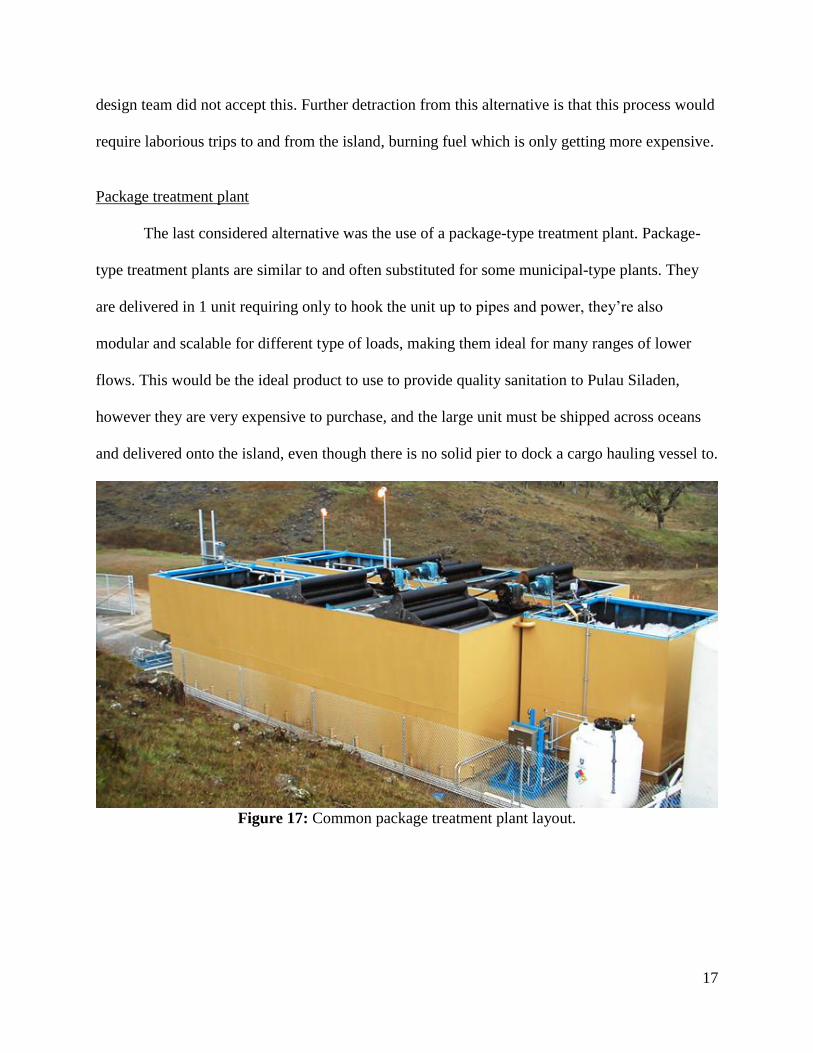
Package treatment plant
The last considered alternative was the use of a package-type treatment plant. Package-
type treatment plants are similar to and often substituted for some municipal-type plants. They
are delivered in 1 unit requiring only to hook the unit up to pipes and power, they’re also
modular and scalable for different type of loads, making them ideal for many ranges of lower
flows. This would be the ideal product to use to provide quality sanitation to Pulau Siladen,
however they are very expensive to purchase, and the large unit must be shipped across oceans
and delivered onto the island, even though there is no solid pier to dock a cargo hauling vessel to.
Figure 17: Common package treatment plant layout.
18
Logic in Selecting a Solution
There were two primary overall considerations taken when determining the best solution
to Pulau Siladen’s wastewater problem: site constraints and economic considerations. For the
site, the solution had to be practical and appropriate for a small island population. Many
traditional solutions are better suited for larger populations, so it is imperative that there is a
solution that is adaptable for Pulau Siladen’s population. The island is remote and difficult to
deliver cargo to unless it can be hauled from a small basic boat on the beach, ruling out the use
of large, heavy or bulky components. There is a mechanical engineer at at least one resort who
can fix machines and systems which is useful for routine maintenance and oversight of the
system with training.
For economic considerations, Indonesia has drastically lower labor costs than America;
their minimum wage ranges from $0.50 to $1.25/hour in American dollars. (Wage Indicator)
That is something the design team considered in its opinion of most probable cost. Shipping
costs were considered in the design because most parts would be produced in America and
shipped over to Indonesia. Operation and maintenance of the system was considered. When
determining the system components, it was imperative to make sure maintenance of the system
was ergonomic. Otherwise the system would be short-lived and would fail. The system was
designed to use readily-available and redundant parts, such as spare pumps, primarily for those
not as readily-available. This would ensure that if those parts fail, they can be replaced and the
system can continue operating without having to wait for replacements or custom parts to be
shipped.
19
Chosen Solution Strategy
After considering the potential solutions to the problems previously mentioned, the most
suitable option was the package-type treatment approach. This system incorporates a gravity
sewer collection system, Sequencing Batch Reactor (SBR) with slow-trickle intermittent sand
filters and finally a disinfection system to remove pathogens before discharge into the reef water.
Treated water pipe will have a valve fitting to divert flow to a chlorine contact chamber to
provide residual disinfection, allowing the treated water to be used as recycled water to offset
potable water demands.
Various methods for providing biological treatment were considered, an SBR was
selected as the most suitable option and the design team determined that only 1 SBR tank would
be required, lending itself merit due to the small land footprint stipulation. The fact that
“equalization, aeration and sedimentation occurs in time sequence batches rather than in the
conventional space sequence of continuous-flow systems”, (Abreu & Estrada) as well as all
processes occurring in just 1 tank further reinforced the decision to incorporate and SBR design.
For such a small community and isolated location with several limitations, this type of system is
the best option. This entire system offers a relatively simple, small-scale solution that is ideal for
the low island population. It is designed to have minimal process control and be easily operated
and maintained by the locals who lack technical expertise.
There are specific constraints that must be considered and designed for. First, the effluent
from the system must be treated to a stringent degree so that it can be safely discharged into the
ocean without harming people or the environment. The system should use readily available parts
with common materials. This will prevent any major issues when replacing parts or finding
spares, should failure occur. One major objective is to minimize the initial and life-cycle cost, so
20
finding cost effective components and materials that are not overpowered or designed, will play
a significant role in the success of this system. Also, due to the location and remoteness of the
island, delivering necessary items is an added burden. Minimizing trips to and from the island for
supplies will save time and money in completing this project. In case of any failure or damage to
parts, ideally enough redundant materials are on site so that any problems may be addressed
immediately. Ordering spare parts may be a lengthy process given the island’s location. Having
redundant materials on hand gives the locals the peace of mind that if issues arise, they may be
resolved in a timely fashion.
21
Project Design Tasks
The project design tasks can be split into two separate categories. The first set of tasks
involves the collection of sufficient data to begin designing. These tasks include researching
environmental discharge standards, determining the average daily wastewater flow on the island,
understanding island topography, and calculating the peak flow for equalization purposes.
Knowledge of the island topography and geographical constraints are required to layout and
design the sewer network and collection system to gather waste from all fixtures effectively. The
second category of the project tasks consist of the actual design of all the treatment system
components. Once the daily flow and peak flow were determined, the equalization sump could
be designed, along with the accompanying piping and components.
The second major system component is the SBR. The design of this involved the design
of the basin itself, including tank sizing and geometry, as well as construction method and
material selection. Equipment to provide the biological treatment has to be considered,
specifically designing a method and component to adequately mix, aerate and decant the water.
Further considerations for the SBR design were in devising a timing schedule for each phase of
treatment, so that timely treatment could occur each day without requiring multiple SBR tanks.
The slow trickle sand filters are the following component in the treatment process which
required design and research. The size, orientation and materials are essential to its operating
efficiency. Another element that is part of the project is the sludge dewatering beds. Along with
the sand filters, the drying beds need to be sized to be able to hold the required capacity and
contain the necessary amounts of materials to perform as desired. The final component as part of
the treatment system is the ultra-violet (UV) disinfection. The UV system must be capable of
providing enough disinfection for the determined flow and treat to reach the required treated

22
effluent standard. All these main components are part of the project design tasks for this project.
Each task requires in-depth research and/or calculation in order to allow the entire system to
function properly.
23
DESIGN CRITERIA
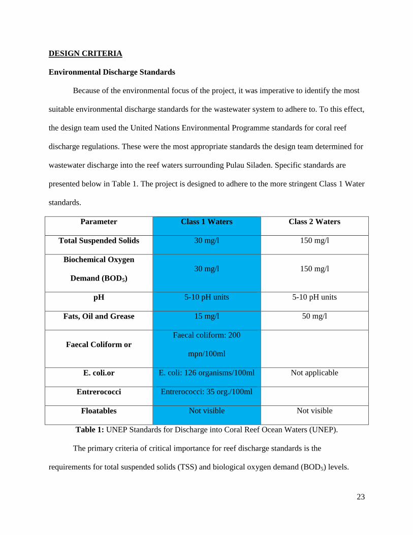
Environmental Discharge Standards
Because of the environmental focus of the project, it was imperative to identify the most
suitable environmental discharge standards for the wastewater system to adhere to. To this effect,
the design team used the United Nations Environmental Programme standards for coral reef
discharge regulations. These were the most appropriate standards the design team determined for
wastewater discharge into the reef waters surrounding Pulau Siladen. Specific standards are
presented below in Table 1. The project is designed to adhere to the more stringent Class 1 Water
standards.
Parameter Class 1 Waters Class 2 Waters
Total Suspended Solids 30 mg/l 150 mg/l
Biochemical Oxygen
Demand (BOD5)
30 mg/l 150 mg/l
pH 5-10 pH units 5-10 pH units
Fats, Oil and Grease 15 mg/l 50 mg/l
Faecal Coliform or
Faecal coliform: 200
mpn/100ml
E. coli.or E. coli: 126 organisms/100ml Not applicable
Entrerococci Entrerococci: 35 org./100ml
Floatables Not visible Not visible
Table 1: UNEP Standards for Discharge into Coral Reef Ocean Waters (UNEP).
The primary criteria of critical importance for reef discharge standards is the
requirements for total suspended solids (TSS) and biological oxygen demand (BOD5) levels.

24
Class 1 standards mandate that average monthly values of TSS and BOD levels must not exceed
30 mg/L. This is also known as the 30-30 rule.
25
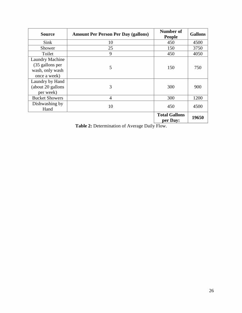
Determination of Average Daily Flow
Average daily flow of wastewater generated is the primary criteria in sizing any WWT
system. In order to size and design the sump, the peak flow must also be known, which is
determined using the average daily flow. The approach chosen to find the average daily flow
took into account all the sources of wastewater on the island from which wastewater would enter
the collection system. Sources such as sinks, toilets, and showers were among the list. The island
contact provided a best guess estimate of the amount of each different source of wastewater
would be on the whole island. Next, the amount of wastewater flow from each source was
researched and altered by estimation. There are currently about 350 people residing on the island.
Most are locals while the rest are tourists. In order to allow for generous population growth on
the island (double that of contact’s population growth estimate), the system was designed to
serve 450 people - 300 locals and 150 guests. The wastewater produced from each source was
measured in gallons per person per day. This number was multiplied by the number of people
using each source. All these factors were added together to equal the total amount of average
flow per day, which was calculated to be 19,650 gallons per day. 20,000 gallons per day was
used instead for the daily flow to be treated. This is equivalent to a flow of 13.9 gallons per
minute of waste entering the system to be treated. The calculations for the determination of
average daily flow are shown below in Table 2.
26
Source Amount Per Person Per Day (gallons) Number of
People Gallons
Sink 10 450 4500
Shower 25 150 3750
Toilet 9 450 4050
Laundry Machine
(35 gallons per
wash, only wash
once a week)
5 150 750
Laundry by Hand
(about 20 gallons
per week)
3 300 900
Bucket Showers 4 300 1200
Dishwashing by
Hand 10 450 4500
Total Gallons
per Day: 19650
Table 2: Determination of Average Daily Flow.
27
SYSTEM COMPONENTS AND DESIGN
Sewer Network Design
With the essential data of expected average daily flow known, the first step is to design
an adequately sized collection system, fed by gravity to convey wastewater from source locations
to the centralized treatment system. Since the calculated 20,000 gallons per day is only an
average, it gives no information as to how much flow will be experienced at one moment, as
wastewater will not be generated at a constant rate throughout the day. Using the Babbit
equation, which considers the island’s population, the peaking factor was determined to be 5 –
the highest value that can be applied in the modeling program ‘SewerCAD V8i’ which was used
to design the sewer network. Using this peaking factor, the peak hourly flow was determined to
be 4200 gallons, all data was inputted in the SewerCAD program. This program is a powerful
tool that calculates using the Manning’s equation, the most appropriate pipe and manhole
characteristics and profiles, mainly slope and pipe diameter requirements. To determine the
required slopes and other criteria, ground elevations and other geographic constraints must be
inputted into the model, to satisfy the required range of 3ft-10ft of pipe cover and full gravity
flow be achieved. Because this is will be a newly constructed sewer network, Infiltration and
Inflow are neglected. After extensive searching, the design team found that no topographic data
is available for Pulau Siladen, so the design team utilized the geographic data afforded by
Google Earth. Using the built-in Google Earth functionality in Civil3D 2011, the design team
was able to import the 3D map provided by Google Earth and set it correct to a standardized
Indonesian Datum and accurate real-world coordinates as seen in Appendix N. A three-
dimensional topographic map was generated with island photo overlay, and since the model is
set to the datum, Civil3D was able to provide elevations relative to sea-level at any location on
28
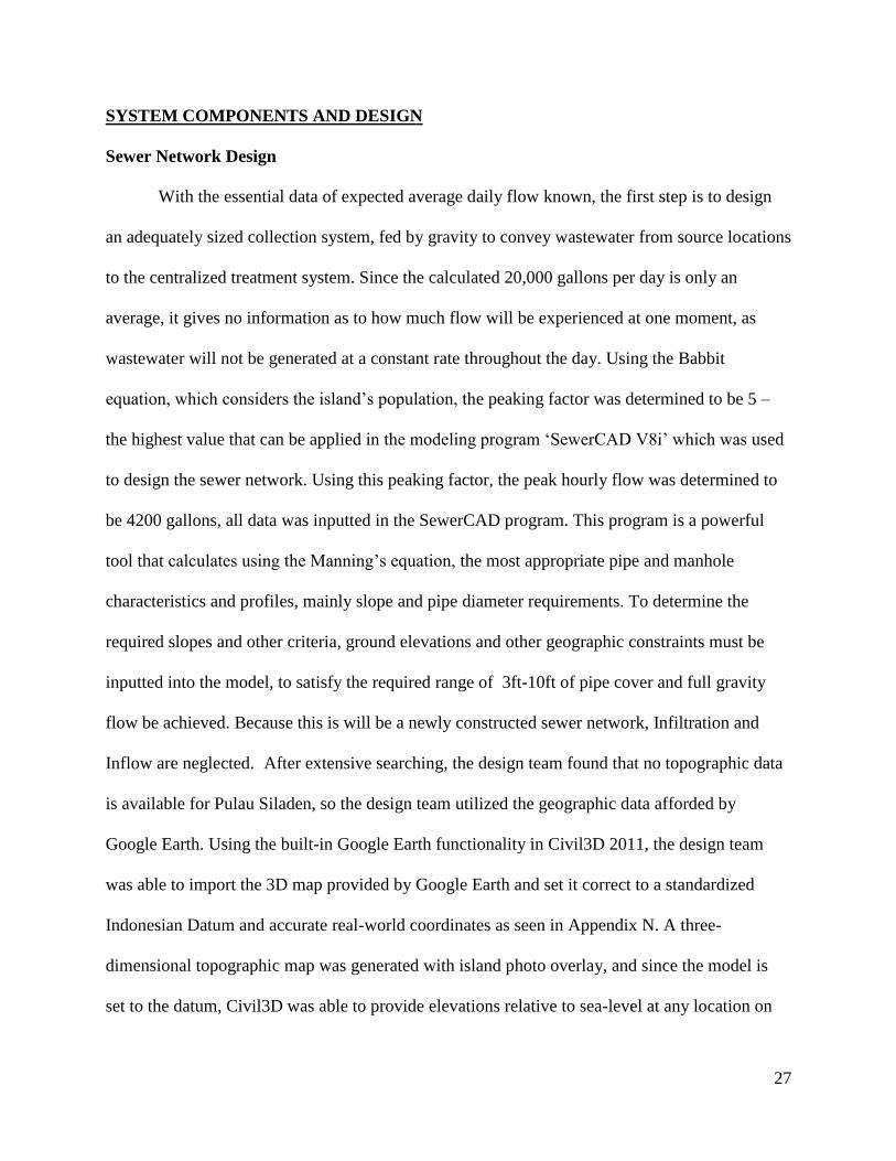
the 3D model. A screen capture of the topographic model used for overall system design as well
as ground elevations for SewerCAD is displayed below in Figure 18, where the thick green line
represents the proposed sewer line installation, under the road, to collect all sources of
wastewater.
Figure 18: Screen capture of generated 3D model.
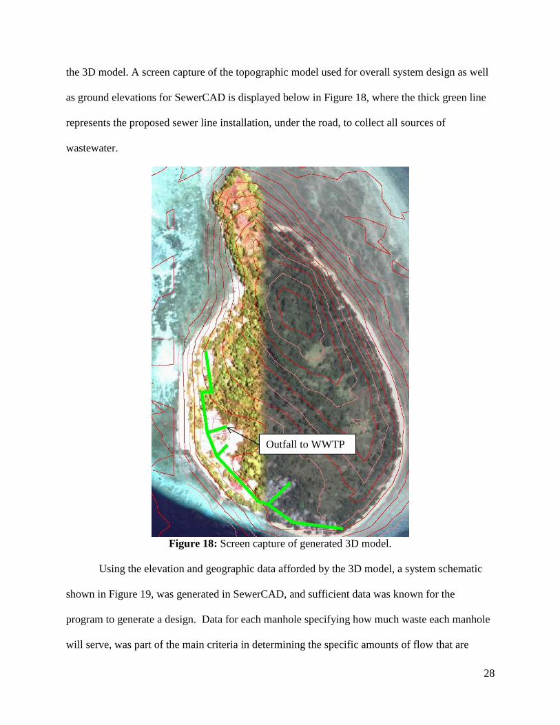
Using the elevation and geographic data afforded by the 3D model, a system schematic
shown in Figure 19, was generated in SewerCAD, and sufficient data was known for the
program to generate a design. Data for each manhole specifying how much waste each manhole
will serve, was part of the main criteria in determining the specific amounts of flow that are
Outfall to WWTP
29
occurring through each pipe in the system, generating component characteristic tables, included
in Appendix A.
Figure 19: Sewer system design schematic.
After many failed network calculations, and tweaking variables, the SewerCAD model
finally displayed no error messages, which indicated that the program was successful in
designing a fully gravity-fed sewer system, meeting required ranges for flow velocity, pipe slope
and cover etc. The conduit characteristic tables in Appendix A, show that extremely low flow is
experienced through the northernmost conduit, meaning that the required minimum flow velocity
of 1ft/s is not satisfied. As a solution, the design team determined that a clean-out valve would be
installed as part of the northernmost manhole, so that flushing may occur, preventing residual
solid buildup in the sewers.
Outfall to WWTP
30
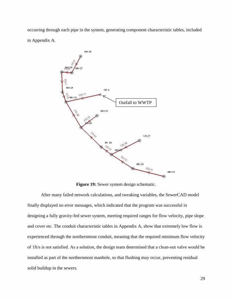
SewerCAD was able to generate pipe profiles with reference to land elevations, depicted
below in Figure 20.
Figure 20: Main pipeline profile, 0 Station represents the system’s northernmost point.
The outfall point depicted in the above images, coincides with a depression in elevation
which is the lowest point in the entire sewer network. After discussion with the island contact, a
site location was selected, described in further sections.
It was determined that the sewer network will be composed of 6” and 8” diameter PVC
pipes. Further pipe information is displayed in the conduit tables in Appendix A. PVC was
identified as the ideal pipe material as it is light, cheap and durable enough for the application at
hand, where concrete or iron piping would be too heavy duty to deliver and construct on Pulau
Siladen. Standard details are provided in Appendix B, that specify pipe and manhole
construction drawings, adapted from the city of San Jose’s published typical details.
Outfall to WWTP

31
Flow Equalization Sump
There exists a large amount of variation in wastewater flow through the sewers at
different times of the day. In general, the “amount of variation tends to increase with a decrease
in sewer system size, because of the lack of damping effects from longer flow times found in
larger systems… The extreme low flow usually occurs between 2am and 6am, with two peaks
occurring during daylight hours around 9am and 6pm.” (Wastewater Treatment - EPA) Because
of the highly varying nature of flow to be expected, the design team wished to equalize the
influent prior to discharge into the SBR for treatment.
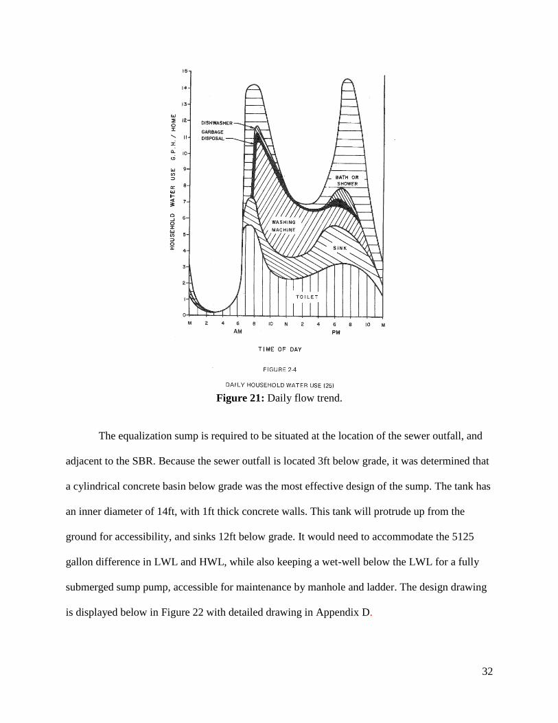
The flow trend depicted in Figure 21 represents the variation in flow of a similar small,
sewered residential community. The design team adapted its assumed flow trends from this
diagram and applied the trend ratios to the average daily flow. The excel calculations can be
found in Appendix C, where the cumulative difference in outflow into the sump and SBR was
calculated, assuming a sump pumping rate of the 13.9 GPM value stated earlier. This allowed for
a calculation of the High water level (HWL) and Low water level (LWL), in determining the
difference in these values which represents the equalization volume of water required by the
sump of 5125 gallons.
32
Figure 21: Daily flow trend.
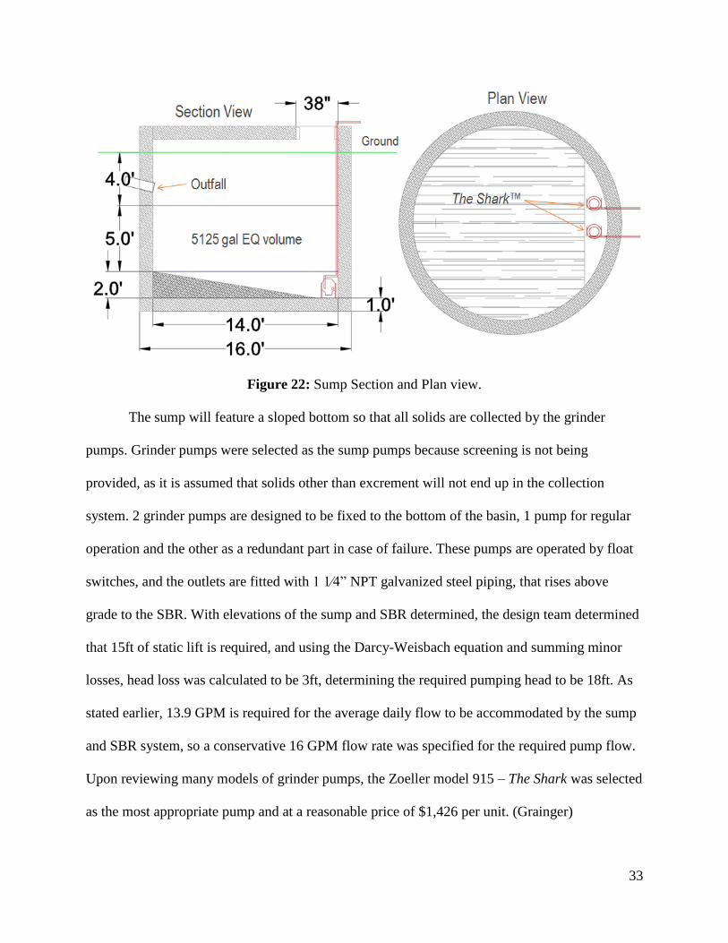
The equalization sump is required to be situated at the location of the sewer outfall, and
adjacent to the SBR. Because the sewer outfall is located 3ft below grade, it was determined that
a cylindrical concrete basin below grade was the most effective design of the sump. The tank has
an inner diameter of 14ft, with 1ft thick concrete walls. This tank will protrude up from the
ground for accessibility, and sinks 12ft below grade. It would need to accommodate the 5125
gallon difference in LWL and HWL, while also keeping a wet-well below the LWL for a fully
submerged sump pump, accessible for maintenance by manhole and ladder. The design drawing
is displayed below in Figure 22 with detailed drawing in Appendix D.
33
Figure 22: Sump Section and Plan view.
The sump will feature a sloped bottom so that all solids are collected by the grinder
pumps. Grinder pumps were selected as the sump pumps because screening is not being
provided, as it is assumed that solids other than excrement will not end up in the collection
system. 2 grinder pumps are designed to be fixed to the bottom of the basin, 1 pump for regular
operation and the other as a redundant part in case of failure. These pumps are operated by float
switches, and the outlets are fitted with 1 1⁄4” NPT galvanized steel piping, that rises above
grade to the SBR. With elevations of the sump and SBR determined, the design team determined
that 15ft of static lift is required, and using the Darcy-Weisbach equation and summing minor
losses, head loss was calculated to be 3ft, determining the required pumping head to be 18ft. As
stated earlier, 13.9 GPM is required for the average daily flow to be accommodated by the sump
and SBR system, so a conservative 16 GPM flow rate was specified for the required pump flow.
Upon reviewing many models of grinder pumps, the Zoeller model 915 – The Shark was selected
as the most appropriate pump and at a reasonable price of $1,426 per unit. (Grainger)

34
Study of the manufacturer’s published specifications and pump performance curve depicted in
Figure 23, show that the required pumping head and flow rate lies in the most efficient range to
pump at, meaning that this pump is the perfect selection for the specified criteria, minimizing
pumping energy requirements.
Figure 23: Pump performance curve for Model 915. Operating in efficient region.

35
Treatment System Components
All wastewater from the entire island is collected by the sewer system and transported to
the location of the treatment system. The actual treatment system is composed of several parts.
The water flows from the sewer into the equalization basin, or sump. The sump collects and
equalizes the flow throughout each day so that there is a constant flow into the sequencing batch
reactor. The sequencing batch reactor (SBR) is an activated sludge process designed to provide
biological treatment in the multiple phases mentioned earlier. The SBR is mainly responsible for
removal of the biological oxygen demand (BOD5) and the total suspended solids (TSS). After a
cycle of SBR treatment, the wastewater is decanted into the slow trickle sand filters. These
provide further filtration of the wastewater. Once the wastewater has traveled through the sand
filters, it is conveyed to the UV disinfection system. The UV system disinfects the wastewater so
that it can be safely discharged into the ocean without fear of exposing swimmers to harmful
pathogens. There is a possible site and system for future chlorination so that some wastewater
may be used towards water reclamation.
In the SBR system, sludge is actively retained in order to biologically treat the
wastewater. However, some of that sludge is removed each day in order to maintain a steady
state in the reactor. The sludge that is removed is manually transported in 55 gallon drums to the
sludge drying or dewatering bed. This drying bed allows the sludge to dry so that it can be used
for land application, as it is a natural fertilizer.
36
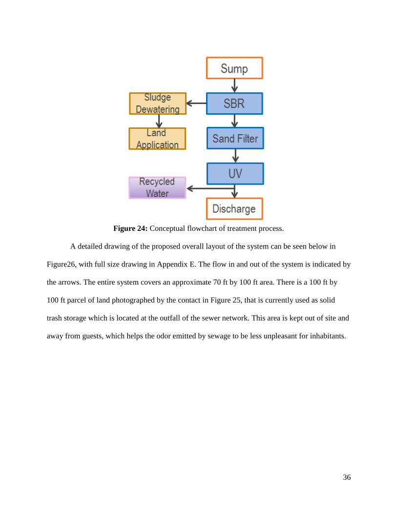
Figure 24: Conceptual flowchart of treatment process.
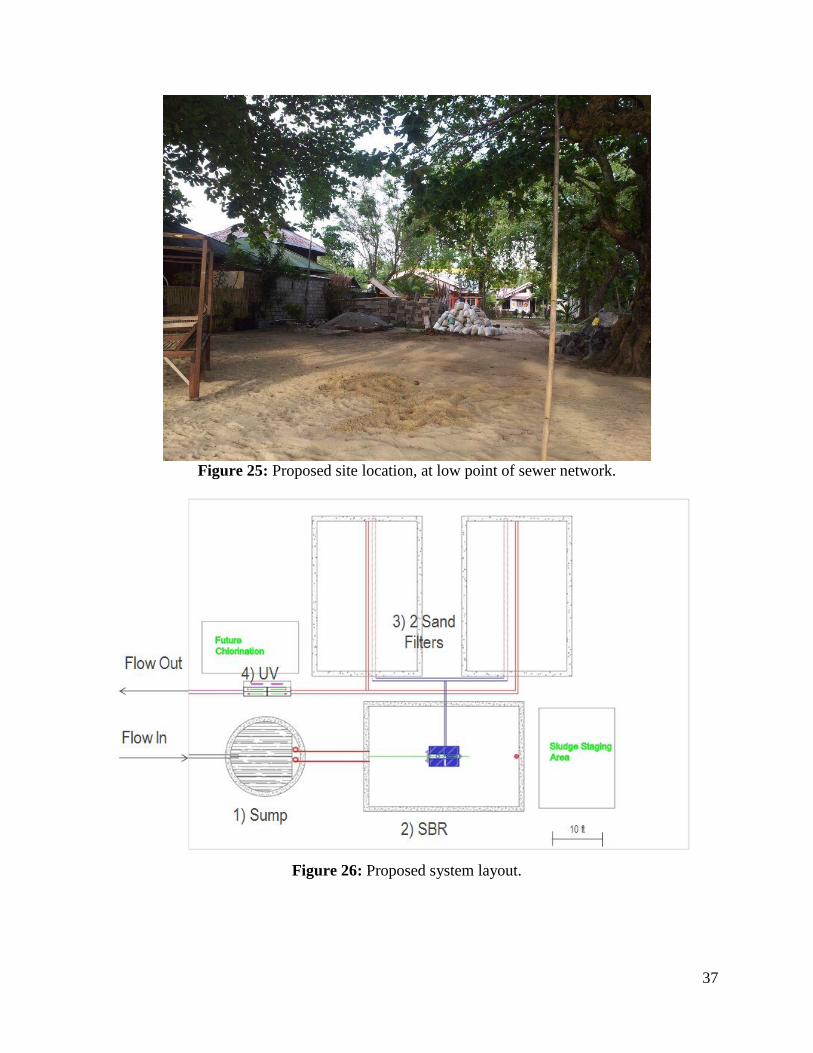
A detailed drawing of the proposed overall layout of the system can be seen below in
Figure26, with full size drawing in Appendix E. The flow in and out of the system is indicated by
the arrows. The entire system covers an approximate 70 ft by 100 ft area. There is a 100 ft by
100 ft parcel of land photographed by the contact in Figure 25, that is currently used as solid
trash storage which is located at the outfall of the sewer network. This area is kept out of site and
away from guests, which helps the odor emitted by sewage to be less unpleasant for inhabitants.
37
Figure 25: Proposed site location, at low point of sewer network.
Figure 26: Proposed system layout.

38
Sequencing Batch Reactor
As mentioned, the Sequencing Batch Reactor (SBR) is the chosen method of treatment
for this project. It uses an activated sludge process to biologically treat wastewater. The process
removes BOD5 and TSS while providing nitrification and denitrification. The system operates in
multiple phases: filling, anoxic mixing, aerobic mixing, settling, and decant.
Figure 27: Flowchart illustrating each SBR phase.
These phases operate on a continuous cycle. In the anoxic phase, influent wastewater is
mixed with the sludge to provide contact between microorganisms and the substrate. This mixing
creates an environment that is favorable for the procreation of microorganisms, and the Anoxic
conditions provide nitrogen removal. The aerobic phase provides oxygen so that the
microorganisms can feed on the substrate. Adjusting the timing of these phases can provide a
simple way to create an environment where nitrification and denitrification occur. The goal is to
have the microorganisms to completely remove all TSS, BOD5 and adequate nitrogen removal.
The amount of removal depends on the length of the phases. The settling phase is when the
aeration and mixing cease to allow separation of solids. The sludge sinks to the bottom leaving

39
treated effluent above. The decant phase removes the treated effluent from the tank lowering the
water level to a designated Low water level. Some of the sludge is then pumped out and
transported to the dewatering bed. Sludge will be wasted through the use of a designated sludge
pump with flexible hose to fill the barrels. The Allegro model 9404-04 submersible sludge pump,
was selected for its relatively low but sufficient pumping head and power requirements. This
model is by far the most cost effective unit after research of potential other products. 2 pumps
will be purchased initially, at $716 per unit. One unit will be fixed in the SBR and the other held
on site as a spare. Manufacturer spec sheet is included in Appendix F. After decant phase
completion, the daily cycle starts over.
During the design process, various methods of constructing the SBR were considered.
The most simple design is a square or rectangular base with surrounding walls and an open top.
A circular tank was also considered but ruled out due to difficulty in construction. A third option
was an earthen basin lined with BIOWORKS lining, a heavy duty, high density polyurethane
lining designed for earthen basins containing sewage. (BIOWORKS) This was the cheapest
option considering materials costs. However, the required footprint it would cover to hold
enough wastewater while maintaining a suitable slope for earth basin stability, far exceeded the
available space, ruling this option out. The most suitable choice for this project is a concrete
rectangular basin. Table 3 displays the potential dimensions calculated for sufficient basin size.
40
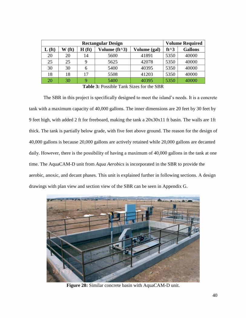
Rectangular Design Volume Required
L (ft) W (ft) H (ft) Volume (ft^3) Volume (gal) ft^3 Gallons
20 20 14 5600 41891 5350 40000
25 25 9 5625 42078 5350 40000
30 30 6 5400 40395 5350 40000
18 18 17 5508 41203 5350 40000
20 30 9 5400 40395 5350 40000
Table 3: Possible Tank Sizes for the SBR
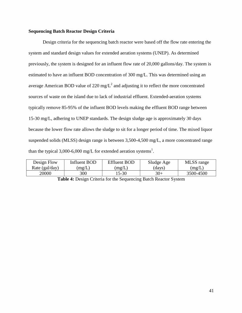
The SBR in this project is specifically designed to meet the island’s needs. It is a concrete
tank with a maximum capacity of 40,000 gallons. The inner dimensions are 20 feet by 30 feet by
9 feet high, with added 2 ft for freeboard, making the tank a 20x30x11 ft basin. The walls are 1ft
thick. The tank is partially below grade, with five feet above ground. The reason for the design of
40,000 gallons is because 20,000 gallons are actively retained while 20,000 gallons are decanted
daily. However, there is the possibility of having a maximum of 40,000 gallons in the tank at one
time. The AquaCAM-D unit from Aqua Aerobics is incorporated in the SBR to provide the
aerobic, anoxic, and decant phases. This unit is explained further in following sections. A design
drawings with plan view and section view of the SBR can be seen in Appendix G.
Figure 28: Similar concrete basin with AquaCAM-D unit.
41
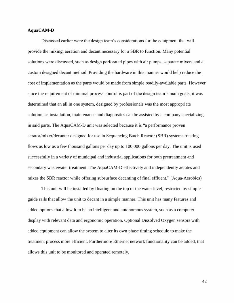
Sequencing Batch Reactor Design Criteria
Design criteria for the sequencing batch reactor were based off the flow rate entering the
system and standard design values for extended aeration systems (UNEP). As determined
previously, the system is designed for an influent flow rate of 20,000 gallons/day. The system is
estimated to have an influent BOD concentration of 300 mg/L. This was determined using an
average American BOD value of 220 mg/L2 and adjusting it to reflect the more concentrated
sources of waste on the island due to lack of industrial effluent. Extended-aeration systems
typically remove 85-95% of the influent BOD levels making the effluent BOD range between
15-30 mg/L, adhering to UNEP standards. The design sludge age is approximately 30 days
because the lower flow rate allows the sludge to sit for a longer period of time. The mixed liquor
suspended solids (MLSS) design range is between 3,500-4,500 mg/L, a more concentrated range
than the typical 3,000-6,000 mg/L for extended aeration systems1.
Design Flow
Rate (gal/day)
Influent BOD
(mg/L)
Effluent BOD
(mg/L)
Sludge Age
(days)
MLSS range
(mg/L)
20000 300 15-30 30+ 3500-4500
Table 4: Design Criteria for the Sequencing Batch Reactor System
42
AquaCAM-D
Discussed earlier were the design team’s considerations for the equipment that will
provide the mixing, aeration and decant necessary for a SBR to function. Many potential
solutions were discussed, such as design perforated pipes with air pumps, separate mixers and a
custom designed decant method. Providing the hardware in this manner would help reduce the
cost of implementation as the parts would be made from simple readily-available parts. However
since the requirement of minimal process control is part of the design team’s main goals, it was
determined that an all in one system, designed by professionals was the most appropriate
solution, as installation, maintenance and diagnostics can be assisted by a company specializing
in said parts. The AquaCAM-D unit was selected because it is “a performance proven
aerator/mixer/decanter designed for use in Sequencing Batch Reactor (SBR) systems treating
flows as low as a few thousand gallons per day up to 100,000 gallons per day. The unit is used
successfully in a variety of municipal and industrial applications for both pretreatment and
secondary wastewater treatment. The AquaCAM-D effectively and independently aerates and
mixes the SBR reactor while offering subsurface decanting of final effluent.” (Aqua-Aerobics)
This unit will be installed by floating on the top of the water level, restricted by simple
guide rails that allow the unit to decant in a simple manner. This unit has many features and
added options that allow it to be an intelligent and autonomous system, such as a computer
display with relevant data and ergonomic operation. Optional Dissolved Oxygen sensors with
added equipment can allow the system to alter its own phase timing schedule to make the
treatment process more efficient. Furthermore Ethernet network functionality can be added, that
allows this unit to be monitored and operated remotely.

43
The design team submitted a design request form to Aqua-Aerobics, with detailed custom
design criteria determined by the team. Project Application Engineer Rungrod Jittawattanarat,
Ph.D. produced a design report included in Appendix H for the CAM-D unit custom for the
project’s design specifications. For the particular characteristics of Siladen’s SBR system, a 10hp
motor unit to provide mixing, aeration and decant pumping was suggested. The “Preliminary
price for equipment listed on the design including freight and standard supervision service is
$192,700.” – Jittawattanarat
Initially the calculated cost of $193,000 was staggering and much higher than expected.
However a premium is always to be paid for a high tech, all-in-one unit with manufacturing
support and guarantee. Most of the options were selected so as to ensure a more autonomous
operation of the unit, however options can be removed depending on budget requirements if
sacrifices to the intelligence of the system are to be accepted.
44
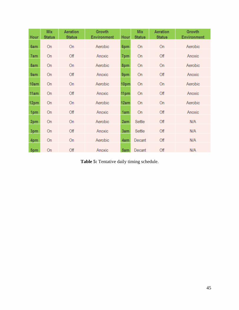
Tentative SBR Daily Timing Schedule
While the AquaCAM-D unit may intelligently alter its phase timing schedule, the design
team developed a tentative SBR daily timing schedule, so that 1 cycle may operate per day to
provide required treatment. Utilizing the same daily flow trend displayed in Figure 21, the design
team considered the high flows experienced during the day, and ~0 flow during the 2am-6am
period. Throughout the day the SBR would be constantly filling and mixing, accounting for the
mix and aeration phases identified as part of the SBR cycle. The settle and decant phases rely on
0 flow entering the reactor so that all particle may settle adequately, thus it was decided to
capitalize on the extreme low flow during early morning hours to accommodate the settle and
decant phases. Apart from the settle and decant phases, the Table 5, below shows that mixing
status is constantly on. Aeration status will be alternated to create and aerobic and anoxic
conditions vital in ensuring proper BOD removal as well as additional denitrification.
A report titled Nitrogen removal in a low-loaded single tank sequencing batch reactor,
by John Palis and Robert Irvine describe the testing set-up and results due to varying aerobic and
anoxic conditions using differing phase timing. The report concludes that by simply ceasing
aeration once adequate nitrification has occurred, the anoxic conditions produced result in
impressive denitrification and increased Ph stability. (Palis & Irvine)
This timing schedule is tentative, and the only way to meaningfully improve the schedule
would be to monitor various chemical concentrations during actual running of the system
specific to Siladen’s SBR. Instead, with the added intelligent options and DO sensor of the
AquaCAM-D unit, the timing schedule can be improved most effectively but the unit
autonomously.
45
Table 5: Tentative daily timing schedule.
46
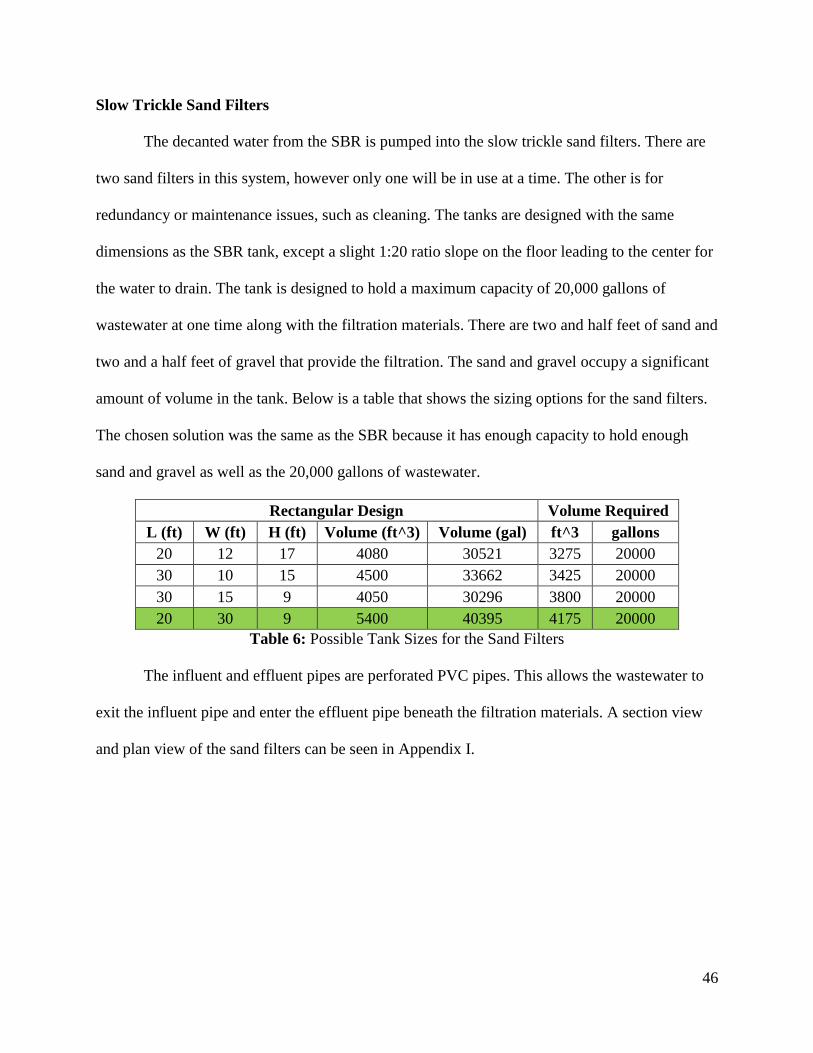
Slow Trickle Sand Filters
The decanted water from the SBR is pumped into the slow trickle sand filters. There are
two sand filters in this system, however only one will be in use at a time. The other is for
redundancy or maintenance issues, such as cleaning. The tanks are designed with the same
dimensions as the SBR tank, except a slight 1:20 ratio slope on the floor leading to the center for
the water to drain. The tank is designed to hold a maximum capacity of 20,000 gallons of
wastewater at one time along with the filtration materials. There are two and half feet of sand and
two and a half feet of gravel that provide the filtration. The sand and gravel occupy a significant
amount of volume in the tank. Below is a table that shows the sizing options for the sand filters.
The chosen solution was the same as the SBR because it has enough capacity to hold enough
sand and gravel as well as the 20,000 gallons of wastewater.
Rectangular Design Volume Required
L (ft) W (ft) H (ft) Volume (ft^3) Volume (gal) ft^3 gallons
20 12 17 4080 30521 3275 20000
30 10 15 4500 33662 3425 20000
30 15 9 4050 30296 3800 20000
20 30 9 5400 40395 4175 20000
Table 6: Possible Tank Sizes for the Sand Filters
The influent and effluent pipes are perforated PVC pipes. This allows the wastewater to
exit the influent pipe and enter the effluent pipe beneath the filtration materials. A section view
and plan view of the sand filters can be seen in Appendix I.
47
Sludge Drying Bed
The purpose of the sludge drying bed is to allow the sludge to be dewatered by the sun
before it is used for land application. Water in the sludge permeates through layers of sand and
gravel and then exits the beds to be put back into the treatment system. This is an
environmentally mindful approach to handling sludge removal, as it requires no power and few,
simple parts compared to other possible solutions like belt or centrifuge dewatering.
The beds are located at an offsite location away from the other treatment system
components. There are eight modules in the drying bed, with each module holding one day’s
generated sludge. The system is designed for a seven day drying cycle. So, seven of the modules
would always be in use, emptying out the oldest sludge in a module and replacing it with new
sludge. The eighth is a redundant module so that any necessary cleaning or maintenance can be
performed without disrupting the seven day cycle. From the calculations included in Appendix J,
there is approximately 250 gallons of sludge per day being removed from the SBR. Each module
was sized according to this value. Each module is five feet by seven feet and almost 4 feet deep.
The entire bed is 17 feet by 25 feet and just over 6 feet high. There are four layers of sand or
gravel. The top layer is one half foot of fine sand. The next layer is one quarter foot of coarse
sand. Then, there is one quarter foot of fine gravel. The bottom layer is one quarter foot of coarse
gravel. A plan view and section view can be seen in Appendix K.
48
Disinfection
During the design process, the project team devised two possible solutions for providing
adequate disinfection to treat the water to a higher quality, safe for swimmers and divers.
Chlorination
Because it is widely used for wastewater treatment systems, chlorination was considered
an option for disinfection. It can also be supplied in various different ways, making it a versatile
treatment option. Unfortunately, the disadvantages associated with water chlorination do not
make it the best option for Pulau Siladen. Three in particular are especially harmful for Pulau
Siladen: chlorine residual is toxic to aquatic life, chlorine’s toxicity would require special
handling, and potential long-term environmental effects (United States Environmental Protection
Agency, 1999). Each of these disadvantages might compromise the goal of improving the area’s
environmental health, so chlorination was not chosen for disinfection.
Ultraviolet Radiation
Ultraviolet Radiation has two key advantages that make it the most preferable solution
for Pulau Siladen. First, there is no residual environmental effect after disinfection (United States
Environmental Protection Agency, 2003). This is important because of the coral reefs that
surround the island. UV systems also require less space and no storage of chemicals, than other
disinfection systems (United States Environmental Protection Agency, 2003). Because of the
limited space on Pulau Siladen, it is ideal to conserve space whenever possible. Between
chlorination and UV radiation, UV radiation is a better solution for wastewater treatment on
Pulau Siladen.
The UV disinfection system is based off the Tipton Environmental TEII-600-AZ model.
Technical information can be found in Appendix L. The unit itself, according to Tipton’s
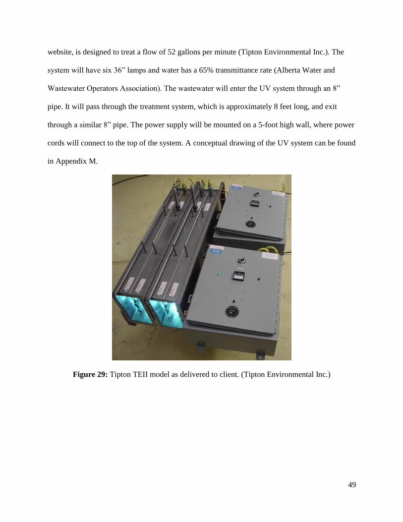
49
website, is designed to treat a flow of 52 gallons per minute (Tipton Environmental Inc.). The
system will have six 36” lamps and water has a 65% transmittance rate (Alberta Water and
Wastewater Operators Association). The wastewater will enter the UV system through an 8”
pipe. It will pass through the treatment system, which is approximately 8 feet long, and exit
through a similar 8” pipe. The power supply will be mounted on a 5-foot high wall, where power
cords will connect to the top of the system. A conceptual drawing of the UV system can be found
in Appendix M.
Figure 29: Tipton TEII model as delivered to client. (Tipton Environmental Inc.)
50
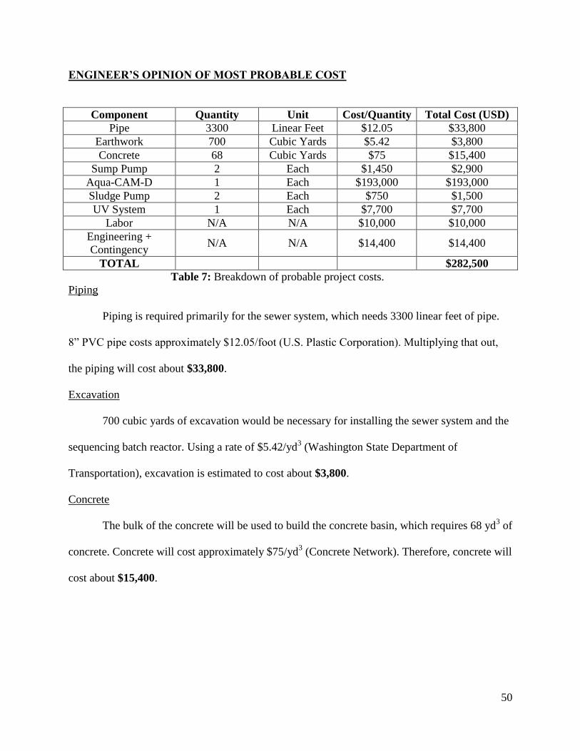
ENGINEER’S OPINION OF MOST PROBABLE COST
Component Quantity Unit Cost/Quantity Total Cost (USD)
Pipe 3300 Linear Feet $12.05 $33,800
Earthwork 700 Cubic Yards $5.42 $3,800
Concrete 68 Cubic Yards $75
$15,400
Sump Pump 2 Each $1,450 $2,900
Aqua-CAM-D 1 Each $193,000 $193,000
Sludge Pump 2 Each $750 $1,500
UV System 1 Each $7,700 $7,700
Labor N/A N/A $10,000 $10,000
Engineering +
Contingency N/A N/A $14,400 $14,400
TOTAL $282,500
Table 7: Breakdown of probable project costs.
Piping
Piping is required primarily for the sewer system, which needs 3300 linear feet of pipe.
8” PVC pipe costs approximately $12.05/foot (U.S. Plastic Corporation). Multiplying that out,
the piping will cost about $33,800.
Excavation
700 cubic yards of excavation would be necessary for installing the sewer system and the
sequencing batch reactor. Using a rate of $5.42/yd3 (Washington State Department of
Transportation), excavation is estimated to cost about $3,800.
Concrete
The bulk of the concrete will be used to build the concrete basin, which requires 68 yd3 of
concrete. Concrete will cost approximately $75/yd3 (Concrete Network). Therefore, concrete will
cost about $15,400.
51
Pumps
Both sump pumps and sludge pumps are ordered as entire units. The project team
received quotes for pumps and determined the probable cost based on those quotes. Because of
redundancy, two of each pump would be ordered. Respectively, the sump pumps will cost $2,900
while the sludge pumps will cost $1,500.
AquaCAM-D
The AQUA-CAM-D is the primary component of the sequencing batch reactor and the
most expensive piece of equipment. Based on a quote from Rungrod Jittawattanarat, Ph.D., the
AQUA-CAM-D will cost approximately $193,000.
Labor and Contingency
While highly variable, it is imperative to set aside money for labor and contingency
purposes. Labor costs are all-inclusive and take into account the lower labor rates in Indonesia.
That being said, $10,000 is being set aside from labor. To ensure that there are enough funds to
compensate for issues that appear in the field, $14,400, (about 8% of the system cost) is being set
aside for engineering and contingency costs.
52
OTHER ISSUES
Non-Technical Issues
The project has four non-technical issues that need to be addressed as it moves forward.
The first one would be handling foreign regulations. While the project has been designed using a
number of assumptions in America, construction and implementation of the system would be
subject to Indonesian laws. It would be imperative going forward to perform extensive research
on Indonesian laws and how they will impact development of the wastewater system. The level
of Indonesian government support and oversight is another non-technical issue associated with
the project. Indonesia currently has widespread sanitation problems within the country.
Management of water sanitation is influenced by government policy at both state and local levels
but currently the roles of government are unclear in water sanitation issues. Having the
government place a greater amount of emphasis on wastewater sanitation would be a boon to the
development of the project. Community support of the project is the third non-technical issue
associated with the project. In terms of infrastructure, the project would have a huge impact on
the island. Installation of the sewer network would require removal of the road on the island and
a whole new wastewater system would be installed. The project is ultimately to improve the
well-being of Pulau Siladen’s community but it would not fulfill its purpose without the support
of the community itself. Finally, determining payment for the project is an underlying issue.
Who would be responsible for paying for the project: residents of the island, resort owners, or the
Indonesian government? There would need to be some sort of resolution regarding payment of
the project before it can move forward.
53
Ethical Issues
Along with non-technical issues, the project has some ethical issues associated with it.
The first is the acquisition of property for the project. Relatively speaking, the project requires a
large amount of land, most of which is currently owned privately. Ethical concerns would arise
with how to acquire that property. Could a fair negotiation for the land be conducted or would
the implementation of eminent domain be required? Environmental impacts associated with
construction of the system pose another ethical issue. Despite the environmental focus of the
project, would it be ethical if the construction damages the environment? It is imperative that the
project construction leaves the environment in as good if not better condition than before the
construction started. Similar to environmental impacts, maintaining adequate public health is an
ethical issue. It needs to be certain that the project will improve the well-being of both the
environment and population before it can proceed. Finally, labor conditions for the project
presents a huge ethical issue. As explained earlier, the minimum wage in Indonesia lags greatly
behind the minimum wage in America. Work in Indonesia is highly susceptible to be exploited
for cheap labor. Ethically speaking, it is important that workers on the project are paid a living
wage and are not exploited.
54
Conclusion
The goal of designing a low-impact wastewater treatment system for Siladen Island was
to develop a system that would treat wastewater in order to both preserve the surrounding
environment and improve sanitation on the island. The main focus of this project was to create a
design that could sufficiently treat wastewater before discharge into the ocean. As a result, the
coral reefs could be preserved and the drinking water supply would not be at risk. The design
team focused on ensuring the system is feasible for a small population while providing an
acceptable amount of treatment to do that. The team was in communication with a resort owner
on the island to ensure accurate design conditions, both regarding population and geography, for
the system. A collection system was designed to ensure that contaminated wastewater reaches
the treatment system in a controlled manner. The wastewater then undergoes treatment within the
sequencing batch reactor and is subsequently treated using ultraviolet radiation. After UV
radiation, the treated water is discharged into the ocean. Overall, the system will provide sewage
treatment with the potential for recycled water production in the future.
Considering this project was conceived from scratch, the wastewater treatment design is
still in a fairly conceptual stage. The current design proves that it is feasible to design a
wastewater treatment system for small islands like Pulau Siladen. The team recommends that
other design teams take the current wastewater system design and expand upon it. One of the
tertiary goals of the project heading in was to design a system that is compatible on islands
similar to Pulau Siladen. A focus on creating a more refined, adaptable solution from using this
current design would be ideal.
55
WORKS CITED
Allegro Industries. Specifications. N.p.: Allegro Industries, n.d. Allegro Safety. 21 Nov. 12. Web.
10 June 2014.
"AquaCAM-D." Aqua-Aerobic Systems. N.p., n.d. Web. 10 June 2014.
"BIOWORKS® Construction Design." Bioworks. N.p., n.d. Web. 10 June 2014.
Castle, James, Todd Callahan, and Andri Manuwoto. Indonesian Business: The Year in Review
2007. N.p.: Equinox, 2010. Google Books. Web. 10 June 2014.
Chow, Ven T., Rolf Eliassen, and Ray K. Linsley, eds. Wastewater Engineering: Collection,
Treatment, Disposal. Montr al: McGraw-Hill, 1972. Print.
"Concrete Price Considerations - Cost of Concrete." ConcreteNetwork.com. Web. 22 May 2014.
CornerstonesMUD.com. Cornerstones Municipal Utility District, n.d. Web. 22 May 2014.
"Disinfection Systems." Tipton Environmental International, Inc. Tipton Environmental
International, Inc., n.d. Web. 22 May 2014.
"Grinder Pump System." Grainger. N.p., n.d. Web. 10 June 2014.
Metcalf & Eddy., George Tchobanoglous. Wastewater Engineering: Collection, Treatment,
Disposal. McGraw-Hill, 1972.
"Minimum Wages in Indonesia." WageIndicator.org. N.p., n.d. Web. 22 May 2014.
Palis, John C., and Robert L. Irvin. "Nitrogen Removal in a Low-loaded Single Tank Sequencing
Batch Reactor." Water Pollution Control Federation57 (n.d.): 82-86. Web. 10 June
2014.
Progress on Drinking Water and Sanitation: Special Focus on Sanitation. New York, NY:
UNICEF, 2008. World Health Organization. Web. 10 June 2014.
"PVC Pipe." USPlastic.com. United States Plastic Corporation. Web.
56
Roosmini, Dwina, and Suphia Rahmawati. "Domestic Wastewater Services and Facilities in
Indonesia: Policy and Regulation Role." Water Environment Partnership in Asia
(2012). Print.
Ryan, John C. "Indonesia's Coral Reefs on the Line." World Watch (2001): n. pag. World Watch.
Worldwatch Institute. Web. 21 May 2014.
"Sequencing Batch Reactors: An Efficient Alternative to Wastewater Treatment." RPI
Department of Chemical Engineering. Rensselaer Polytechnic Institute, n.d. Web. 22
May 2014.
"Siladen Island Manado : Suitable for Swim, Snorkeling and Diving." Visit Indonesia Today.
N.p., 13 Dec. 2011. Web. 10 June 2014.
"Siladen Weather, Indonesia." World Weather Online. N.p., n.d. Web. 10 June 2014.
"Sustainability - Siladen Resort & Spa, Bunaken Marine Park, Indonesia." Siladen Resort Spa
Bunaken Marine Park Indonesia. N.p., n.d. Web. 21 May 2014.
"The Caribbean Environment Programme." Wastewater, Sewage and Sanitation. United Nations
Environmental Programme, n.d. Web. 22 May 2014.
United States of America. Environmental Protection Agency. Office of Water. Wastewater
Technology Fact Sheet: Chlorine Disinfection. N.p.: n.p., 1999. Web.
United States of America. Environmental Protection Agency. Wastewater Technology Fact
Sheet: Disinfection for Small Systems. N.p.: n.p., 2003. Web.
"UV Disinfection." (n.d.): n. pag. Alberta Water and Wastewater Operators Association. Web. 22
May 2014.
"Wastewater, Sewage and Sanitation." The Caribbean Environment Programme. N.p., n.d. Web.
09 June 2014.

57
Wastewater Treatment: Facilities for Sewered Small Communities. Washington: U.S.
Environmental Protection Agency, 1977. Print.
Whelpton, Leigh. "Untreated Wastewater Kills Coral." Yale Environment Review. Yale School of
Forestry & Environmental Studies, 2012. Web. 10 June 2014.
"WSDOT - Construction Cost Indices." WSDOT - Construction Office. Washington State
Department of Transportation, Mar. 2014. Web. 22 May 2014.