Design of a Cryogenic Tissue Pulverizer for Biochemical...
65
Design of a Cryogenic Tissue Pulverizer for Biochemical Analysis Preparation Sara Alford – Team Leader Christine Koranda – Communications Carla Maas – BWIG Ryan Roth – BSAC Biomedical Engineering Design 402 University of Wisconsin – Madison May 7, 2003 Advisor: Paul Thompson Clients: Jeff Ross and Charles Tessier
Transcript of Design of a Cryogenic Tissue Pulverizer for Biochemical...

Design of a Cryogenic Tissue Pulverizer for Biochemical Analysis
Preparation
Sara Alford – Team Leader Christine Koranda – Communications
Carla Maas – BWIG Ryan Roth – BSAC
Biomedical Engineering Design 402 University of Wisconsin – Madison
May 7, 2003
Advisor: Paul Thompson Clients: Jeff Ross and Charles Tessier
2
Abstract:
The cryogenic tissue pulverizer processes surgically-removed tissue by freezing and grinding the sample into a powder (10 µm diameter particles). To accomplish this task, our design incorporates a pneumatic driven grinding head with a grinding chamber. After careful consideration between motor and pneumatic driven designs, a pneumatically grinding mechanism was chosen for the final design. The pneumatic cylinder, controlled by a timer circuit and solenoid, delivers the power needed to grind the sample. The sample is placed in a grinding chamber surrounded by a polystyrene insulated cooling chamber containing a dry ice and alcohol bath. This ensures that the tissue will remain frozen throughout the grinding process. A detachable grinding head attaches to the pneumatic cylinder and pulverizes the sample. The contour of the grinding head and the curvature of the grinding chamber were matched in order to maximize tissue contact. Our efforts this semester have been focused on building a working prototype. It was tested using liver tissue samples and its performance compared to the existing method using a mortar and pestle. Design Problem:
To design a device that completes the preparation process done manually to prep a tissue sample for biochemical analysis. The device should freeze the tissue (with liquid nitrogen), and grind it to a powder. The sample should be easily collected. Overview of Project Work:
Work on this project began in BME 301 during the spring semester of 2002.
Initial design mechanism for the grinding method and background research was focused
on during that semester. Three designs were initially considered. The next semester, fall
2002, focused on choosing a method to deliver the power needed to grind. A motor
driven and pneumatic driven design were explored thoroughly before choosing a
pneumatically powered grinding mechanism. Initial testing to determine the best
mechanism of pounding and shape of the grinding head and bowl were undertaken. Near
the end of the semester, the development of a prototype was started. This last semester
continued work on the prototype, including the designing of a sample grinding chamber
and cooling chamber. An electrical timing circuit was made to control the pounding rate
of the grinding head. The prototype was working by mid-semester, and then tested with
liver samples in the lab to rate its performance. The project was displayed at the
3
engineering EXPO, and was awarded an honorable mention as well as a K-12 Outreach
Award. A patent proposal was submitted, but was not accepted by WARF.
Background:
Biological and Clinical Rationale
When a tumor is removed from a patient during a surgical resection, a pathologist
analyzes it with microscopy. The information about the tumor cells obtained through this
method is often insufficient to determine precisely what kind of treatment is most
effective for the patient. A more accurate and informative analysis of the tissue is
desired, and therefore the tissue sample is sent to a molecular biology laboratory for
profiling of DNA, RNA, and protein. This information is important in determining a
possible specific treatment that may inhibit or decrease tumor growth. However, before a
profile can be completed, the tissue sample must be preserved and prepared for the
molecular testing. The current preparation procedure involves freezing the sample with
liquid nitrogen and using a mortar and pestle to grind up the sample to a fine powder.
This process is tedious and time-consuming. A molecular biologist may spend several
hours per day solely grinding samples. Our proposed device would replace the current
manual preparation of tissue samples, allowing the researcher to spend his/her time on
other tasks. Ultimately, this device would be placed in a clinical setting so that a
physician or other health care staff could simply insert the fresh extracted sample and
later remove the ground sample, to be sent to a laboratory for testing.
Design Requirements and Constraints
The final design must fulfill several client requirements (Appendix A). The
device should freeze a tissue sample, less than a gram in mass, with liquid nitrogen and
subsequently grind the sample to a powder the consistency of powdered sugar (10 µm
diameter). After analysis, the sample should be efficiently collected. The device needs
to have the capability to prepare 40 tissue samples per day, with each sample processing
time less than or comparable to the manual processing time of 15 minutes. All parts in
contact with the tissue sample should be removable or easily cleaned to avoid cross
contamination of tissue samples. Lastly, the device should fit on a laboratory bench.

4
Cryogenic System Design Considerations:
Due to the use of liquid nitrogen, our group needs to be aware of its implications
to the overall design. In general, a cryogenic storage device must be designed to
withstand forces resulting from internal pressure, the weight of contents, and bending
stresses. All materials that come in contact with the sample must withstand the cold
temperature of liquid nitrogen (-196o C).
Most cryogenic devices are based on the concept of a dewar flask principle – a
double walled container with the inner space being well insulated. In this design, the
inner vessel is constructed of a material compatible with the cryogenic fluid, making
material compatibility a major factor in designing a system (Flynn, 1997).
Properties and behavior of materials included must be considered at low
temperatures since they often vary significantly from room temperature. These factors
include thermal properties such as the ability to conduct heat as well as thermal
expansivity, a material’s cyclic expansion and contraction due to a change in temperature
from low to room temperature.
It also includes mechanical properties such as ductility and brittleness. Materials
exhibiting low-temperature embrittlement should not be used in cryogenic systems.
When a material is subjected to a force of high enough stress level, the elastic behavior of
the material will no longer hold. The material becomes brittle, breaking without any
more deformation, or becomes ductile, permanently deformed. Both results lead to
system failure and inadequate performance. Material’s brittleness is related to its ability
to dislocate under stress, which is related to structure. Metals, specifically face-centered
cubic (fcc) metals and their alloys, are most often used in cryogenic equipment. These
materials include metals such as aluminum, copper, and nickel. The body-centered cubic
(bcc) and the hexagonal close packed metals are less desirable low-temperature devices
because they are more apt to become brittle. Plastics and glass are less desirable
materials because they tend to be very brittle and can shatter upon contact with a
substance as cold as liquid nitrogen. When stress is applied to glass, atomic bonds in the
structure rupture causing the propagation of a crack resulting in a fracture of the glass
piece (Flynn, 1997).

5
Important considerations must also be taken into account concerning the use of
liquid nitrogen in this device. Some general properties of liquid nitrogen are given in
Table 1.
Property Value *Molecular weight of N2 28.01 g/mol §Boiling Point (at 1 atm) -196o C §Density 8.07x10⁵ g/m3 *Heat of Vaporization 199 kJ/kg §Nitrogen gas evolved per volume liquid nitrogen
0.7 m3 vapor per 1 L (0.001 m3) liquid nitrogen
Table 1: Properties of Liquid Nitrogen (N2). Information from the following sources *(“Periodic Table”, 2002), §(MacNeil, 2002).
In general, the container that holds liquid nitrogen must be a good insulator. A
dewar is a specially made container designed to hold substances as cold as liquid
nitrogen; unfortunately, most dewars are expensive. A thermos is an alternative container
for liquid nitrogen; however, the liquid nitrogen will evaporate faster, and the outside of
the thermos will become very cold to touch ("Physics Van", 2002). Evaporation of the
liquid nitrogen will cause high pressure inside the thermos. Drilling a hole in the thermos
allows nitrogen vapor to escape preventing explosions. Care must also be taken when
handling liquid nitrogen to prevent serious frostbite burns resulting from direct contact
with liquid nitrogen or contact with a surface that was cooled by liquid nitrogen. Safety
glasses and waterproof welder’s gloves should be worn (K3PGP Experimenter’s Corner,
2002). Since the nitrogen gas that evolves from the liquid state can also be hazardous,
liquid nitrogen should only be used in well-ventilated areas (MacNeil, 2002).
An insulated chamber containing a coolant can also be used to surround a desired
area to prolong the time the chamber is cool. Dry ice or dry ice with alcohol can be used
as a coolant. To contain the coolant, polystyrene foam insulation can be used. This is a
non-deteriorating and vapor-proof material used commonly to ship dry ice around the
country (ansciproducts.com, 2002).
6
Existing Grinding Products on the Market
A comprehensive search of existing products on the market solidified the need for
the designing of a new device. Devices currently being sold do not meet all requirements
set by our client. Although most products grind tissue, they are not compatible with
liquid nitrogen. The following devices were considered in detail to aid design of our
cryogenic tissue pulverizer:
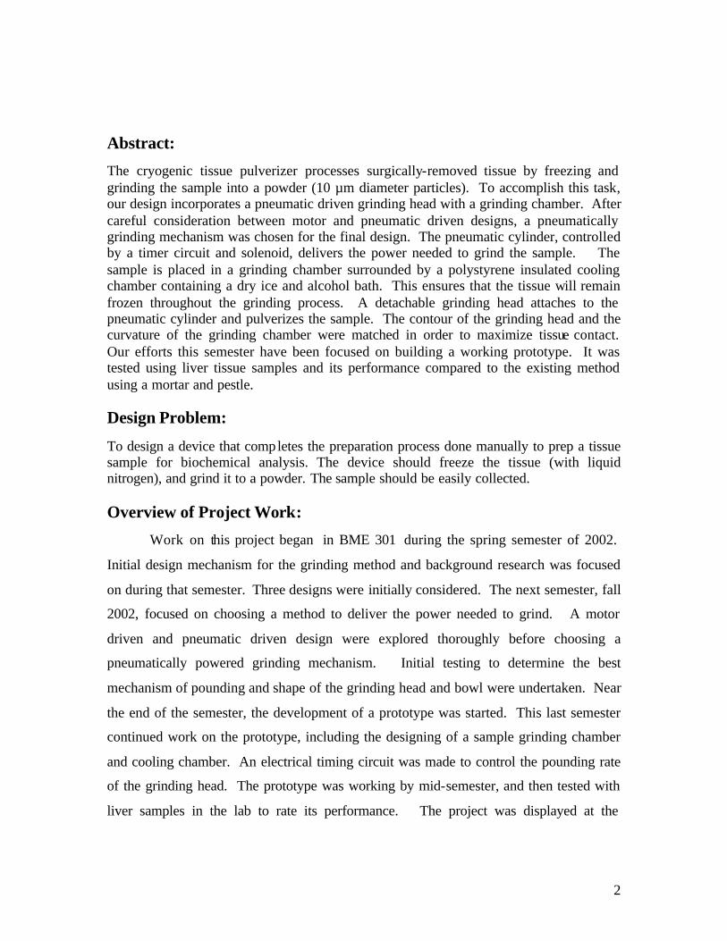
BeadBeater
Biospec Products, Inc. currently produces the BeadBeater (Figure 1), a bead
milling homogenizer. This device is used to disrupt small cells like yeast. The machine
operates by stirring and agitating glass beads, which collide with cells, resulting in
crushing. Recently researchers have begun using the BeadBeater to grind plant and
animal tissue with bead sizes of 1.0 to 2.5 mm. The beads are available in glass, stainless
steel, zirconia, chrome steel, and tungsten. Tougher materials require beads with a higher
density (Meyer, 2002).
Figure 1: The BeadBeater . The top unit spins the metal or glass beads to create collisions with the tissue particles. The collision force breaks apart the tissue (Meyer, 2002). Image from <http://www.biospec.com>.
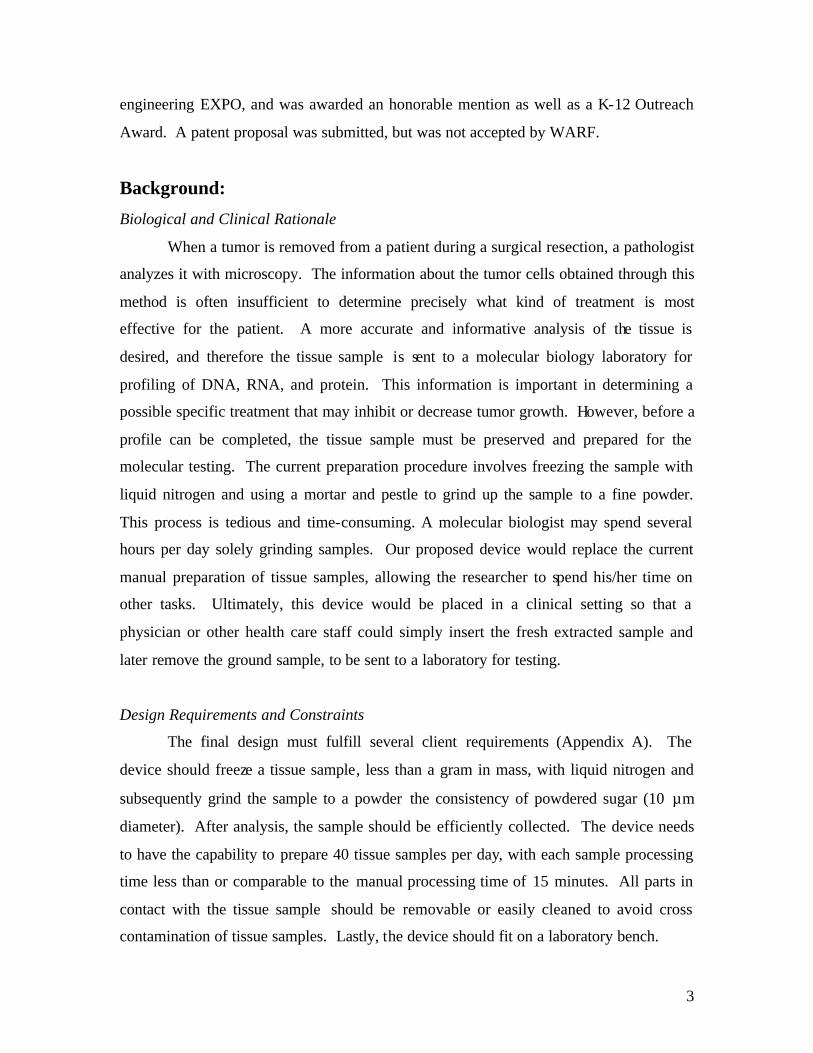
Pestle and tube homogenizer
Pestle and tube homogenizers (Figure 2) consist of a Teflon pestle precisely fitted
to a tube. The distance between the tube and pestle is specialized for the particular cell
type to be homogenized. The pestle spins and grinds the sample with a shearing force.
The pestle is pushed downward and the sample can only pass the spinning pestle if it is

7
smaller than the clearance between the tube and pestle (Seetharam and Sharma, 1991).
The tube is typically placed in a beaker of ice to keep the tissue cold. The main problem
with homogenizers is preparation, as the tissue must be grinded prior to processing
(Burgess, 2002).
Figure 2: The Potter-Elvehjem Homogenizer (LabGlass, 2002). The precision-fit tube is on the left, and the pestle that is attached to a motor is shown on the right. To homogenize a sample, the pestle is forced downward to the bottom of the tube. Image taken from <http://www.lab-glass.com>.
Bio-Pulverizer
The Bio-Pulverizer consists of a stainless steel base and a piston that uses freeze
fracturing to grind a tissue sample. The tissue is pre-frozen with liquid nitrogen and
inserted into a pre-cooled base. The piston and spring loaded hammer are connected via
a trigger loaded mechanism (Figure 3). The sample is then pounded once or twice to
achieve desired consistency. It is then inverted to drop sample into appropriate collection
vial (Meyer, 2002).
Figure 3: Images of the Bio-pulverizer. The spring loaded bio-pulverizer is shown on the left. The mortar and piston are shown individually on the right. This device grinds by freeze fracturing. Image taken from <http://www.biospec.com/Brochures/cryog/BioPulv.html.>
8
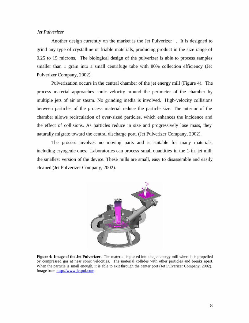
Jet Pulverizer
Another design currently on the market is the Jet Pulverizer . It is designed to
grind any type of crystalline or friable materials, producing product in the size range of
0.25 to 15 microns. The biological design of the pulverizer is able to process samples
smaller than 1 gram into a small centrifuge tube with 80% collection efficiency (Jet
Pulverizer Company, 2002).
Pulverization occurs in the central chamber of the jet energy mill (Figure 4). The
process material approaches sonic velocity around the perimeter of the chamber by
multiple jets of air or steam. No grinding media is involved. High-velocity collisions
between particles of the process material reduce the particle size. The interior of the
chamber allows recirculation of over-sized particles, which enhances the incidence and
the effect of collisions. As particles reduce in size and progressively lose mass, they
naturally migrate toward the central discharge port. (Jet Pulverizer Company, 2002).
The process involves no moving parts and is suitable for many materials,
including cryogenic ones. Laboratories can process small quantities in the 1- in. jet mill,
the smallest version of the device. These mills are small, easy to disassemble and easily
cleaned (Jet Pulverizer Company, 2002).
Figure 4: Image of the Jet Pulverizer. The material is placed into the jet energy mill where it is propelled by compressed gas at near sonic velocities. The material collides with other particles and breaks apart. When the particle is small enough, it is able to exit through the center port (Jet Pulverizer Company, 2002). Image from http://www.jetpul.com.

9
Grinding Mechanism Design Alternatives:
To simplify and focus efforts, our group initially divided the project into different
components: cooling/freezing, grinding, and sample collection. During the first semester
of this project, the grinding method was deemed most important and central to the design
of our device. Focus was directed towards possible mechanisms for grinding; assuming
liquid nitrogen could be pumped or poured via an undetermined mechanism. Our
preliminary design solutions included a plethora of mechanisms such as sliding plates,
beads, pressurized air, pounding hammers, blenders, and funnels. From these designs, we
chose to focus on three main ones to seriously consider and develop further. Based on
test results grinding mechanism effectiveness, as well as other criteria, the grinding
mechanism was chosen.
Grinding Mechanism # 1: The Blender
One design option explored was the blender (Figure 5). Operating like a kitchen
blender, this design uses sharp blades to break frozen sample into fine particles. Blades
are connected through a metal shaft to a motor, which supplies the energy needed to
break the sample. By covering the blending area with a lid, sample loss is prevented.
After the sample is broken, it is washed into the collection vial through the discharge port
with small amounts of liquid nitrogen. The discharge port is selectively opened when the
sample has finished blending.
Figure 5: Blender. The sample is cut into smaller pieces by the spinning blades of the blender. The liquid nitrogen spray will wash the samp le through the discharge port and into the collection vial.

10
Grinding Mechanism # 2: A Funnel Grinder
This design uses a metal cone that rotating around its central axis to grind the
sample. After a sample insertion, the motor rotates the cone creating a shear force
against the sample. Only particles sizes of appropriate size are allowed through the
discharge port into the vial (Figure 6).
Figure 6: Funnel Grinder. The motor spins a cone shaped grinder to break apart the sample by shear forces. When the sample reaches an appropriate size it enters the collection vial through the discharge port. Grinding Mechanism # 3: The Impulse Sampler
The impulse sampler design incorporates the same catabolic mechanism as the
cryogenic pulverizer, but attempts to further the process using automation (see Figure 7).
After the sample is then pulverized and consequently broken into smaller particles by
impulses from the pulverizing head. A motor controls the impulses through a spiral gear,
raising the head with each turn of the motor.

11
Figure 7: Impulse Sampler. The impulse-sampler freezes tissue samples with liquid nitrogen and processes them with impulses delivered by the motor.
Evaluating of Early Grinding Designs:
Initial Testing:
To better evaluate our designs, our group decided to conduct initial testing. We
tested the following methods: two plates sliding past each other, a shaker with ball
bearings, a rotating pestle and a hammer repetitively pounding (Pictures in Appendix B).
Two flat surfaces, providing shear forces to the frozen tissue sample, did not adequately
grind the sample. This process only shredded small layers of cells. Next, we looked at
metal beads in a confined container. The sample stuck to the beads and was hard to
isolate. The hammering test revealed the need for a sample containment mechanism.
Otherwise, sample tended to project bits outward. With an enclosed container, it was
broken into smaller pieces, not a fine powder. We then decided to try the rotating pestle
motion. This motion did not initially break the sample appropriately, but was the best
method for achieving a fine powder once the sample was preprocessed into smaller
pieces. Based on these results, a hybrid design incorporating a pounding hammer motion
first, switching to a rotating pestle motion later would provide optimal grinding of frozen
tissue.

12
Another observation helped realize the importance of cooling. The tissue
remained frozen for around 3 – 5 minutes after being exposed to room temperature
directly after immersion in liquid nitrogen. This led to trouble maintaining frozen tissue
samples. Thawing and refreezing led to tissue freezing hard onto surfaces.
Evaluation Process:
Each of these grinding designs had its advantages as well as disadvantages. As
shown in the design matrix (table 2), we used appropriate criteria to judge each design.
Grinding efficiency, due to its importance, was weighted by a factor of 4.
Criteria Blender Funnel Grinder Impulse Sampler
Grinding Efficiency (4x) - - 0 Simplicity + + 0 Sample Collection Efficiency - + + Durability 0 + + Noise Acceptability 0 + 0 Cleaning - 0 + Processing Time 0 + + Pressure Release + + + Total + 2 6 5 Total 0 3 1 3 Total - -6 -4 0 Total Score -4 2 5
Table 2: Design Matrix. Eight criteria were used to evaluate the three grinding designs, with grinding efficiency weighted by a factor of 4. A plus (+) was given when the design met the criteria. A zero (0) was given when the design neither met the criteria nor failed. A minus (-) was given to the design if it failed the criteria. The total score was obtained by adding all criteria with pluses equal to 1, zeros equal zero, and minuses equal to –1.
Based on this initial evaluation of the gr inding mechanism, the impulse sampler
was chosen for our final design. The exact grinding sequence incorporates several hard
impact pounds to break up the sample followed by rotation of the head around its central
axis, providing shear force. This combination effectively produces a homogenous fine
powder.
Grinding Head Shape and Chamber Design:
Next, further testing was conducted to determine the most effective grinding head
shape and grinding container. The grinding effectiveness of three different objects was

13
tested to help determine the optimal grinding chamber design and head shape. The three
sets of stainless steel grinding tools included round bowls with slanted sides, a flat
bottomed (7.6 cm) soup ladle with completely rounded surfaces (4.1 cm) and common
kitchen spoons with completely rounded surfaces. Comparisons of the bowls to the
ladles test for shape, while, comparisons of the ladles to the spoons test for size. Each
testing set was composed of two duplicate items (i.e. two identical bowls) to achieve a
close fit during grinding of shelled peanuts.
We performed preliminary testing to identify the best method for testing. The
same person pounded to avoid inconsistencies in pounding force. A board was used to
distribute the force over the grinding object. Approximately 15 impulses were applied to
the bowls and ladles, while only 1 pound was applied to the spoons.
We observed a heterogeneous mixture resulting from the slanted bowl. Smaller
peanut particles were present around the periphery of the sample. We attributed this
result to the edges grinding more effectively than the flat surface. Overall the soup ladles
ground the sample to a much smaller homogenous consistency with the same amount of
pounding, suggesting that the rounded surfaces are more effective at grinding. The
spoons pulverized the peanuts to a small powder with only 1 pound. This suggests that a
smaller area concentrates the force to grind the material better. This is probably due to
the increased pressure on the peanuts since the spoon has a smaller surface area than the
ladle. Since pressure is the force per unit of area, smaller areas with the same force will
have higher levels of pressure. This is also intuitive since the same force was applied to
many more peanuts in the ladle (approximately 15) than in the spoons (2 peanuts).
Future testing could be more quantitative. The average size of the larger peanut
particles could be recorded. Since our client wants a fine powder, we found qualitative
observation an acceptable method of analysis, especially since each tool set had clear
differences in resulting particle size. Another improvement to this experiment would be
the use of frozen materials to more accurately represent the frozen tissue. Due to the
limitations of our room temperature setting (no cooling materials such as dry ice or liquid
nitrogen), we did not test frozen materials such as chicken breast.
14
Grinding System Design Alternatives:
Based on initial testing data, the group tackled the overall grinding system design.
Two plausible methods of powering the grinder were designed: motor driven or
pneumatically driven.
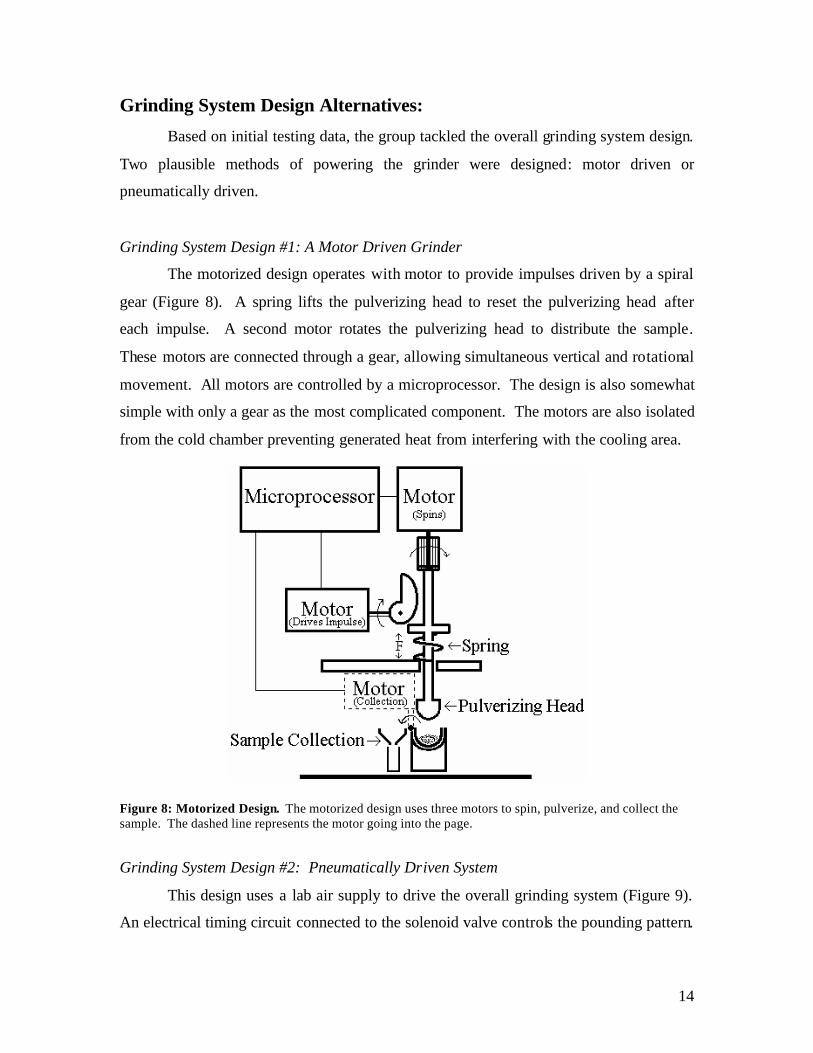
Grinding System Design #1: A Motor Driven Grinder
The motorized design operates with motor to provide impulses driven by a spiral
gear (Figure 8). A spring lifts the pulverizing head to reset the pulverizing head after
each impulse. A second motor rotates the pulverizing head to distribute the sample.
These motors are connected through a gear, allowing simultaneous vertical and rotational
movement. All motors are controlled by a microprocessor. The design is also somewhat
simple with only a gear as the most complicated component. The motors are also isolated
from the cold chamber preventing generated heat from interfering with the cooling area.
Figure 8: Motorized Design. The motorized design uses three motors to spin, pulverize, and collect the sample. The dashed line represents the motor going into the page.
Grinding System Design #2: Pneumatically Driven System
This design uses a lab air supply to drive the overall grinding system (Figure 9).
An electrical timing circuit connected to the solenoid valve controls the pounding pattern.
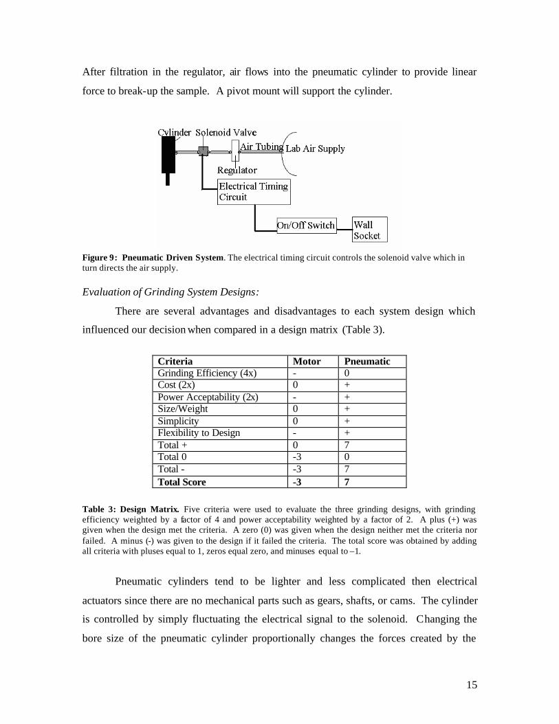
15
After filtration in the regulator, air flows into the pneumatic cylinder to provide linear
force to break-up the sample. A pivot mount will support the cylinder.
Figure 9: Pneumatic Driven System. The electrical timing circuit controls the solenoid valve which in turn directs the air supply.
Evaluation of Grinding System Designs:
There are several advantages and disadvantages to each system design which
influenced our decision when compared in a design matrix (Table 3).
Criteria Motor Pneumatic Grinding Efficiency (4x) - 0 Cost (2x) 0 + Power Acceptability (2x) - + Size/Weight 0 + Simplicity 0 + Flexibility to Design - + Total + 0 7 Total 0 -3 0 Total - -3 7 Total Score -3 7
Table 3: Design Matrix. Five criteria were used to evaluate the three grinding designs, with grinding efficiency weighted by a factor of 4 and power acceptability weighted by a factor of 2. A plus (+) was given when the design met the criteria. A zero (0) was given when the design neither met the criteria nor failed. A minus (-) was given to the design if it failed the criteria. The total score was obtained by adding all criteria with pluses equal to 1, zeros equal zero, and minuses equal to –1.
Pneumatic cylinders tend to be lighter and less complicated then electrical
actuators since there are no mechanical parts such as gears, shafts, or cams. The cylinder
is controlled by simply fluctuating the electrical signal to the solenoid. Changing the
bore size of the pneumatic cylinder proportionally changes the forces created by the
16
cylinder. Pneumatics allow for continuous application of force, facilitating sample
pulverization. The pneumatic grinder also has several disadvantages. It is difficult to
stop the piston during a stroke. This may be a safety issue. Maintenance and repair will
require both electrical and pneumatic experts, increasing maintenance cost.
The motorized design is also expected to be more cost effective and smaller than
the pneumatic design. The smaller size is better for laboratories where lab bench space is
often limited. Also, the lab does not need access to compressed air. The motorized
design is not without disadvantages. The motorized design is not able to provide
continuous force but instead delivers impulses, which are a less effective means of
grinding. Motor electronics will less likely experience resistivity changes due to the cold.
Our final decision to use pneumatic power was further supported by professor
advice. Initially, in conversations with Professor Roderic Lakes, we learned that using an
electrical motor is an indirect way to apply force since it changes electricity to circular
motion to linear motion. For an electric grinder, he suggested seeking out other options.
Upon hearing the requirements of our design Professor Frank Fronczak highly
recommended pneumatic power for our final design. Taking their advice, pneumatic
power was chosen for our final design and warranted a thorough background search on
pneumatic systems.
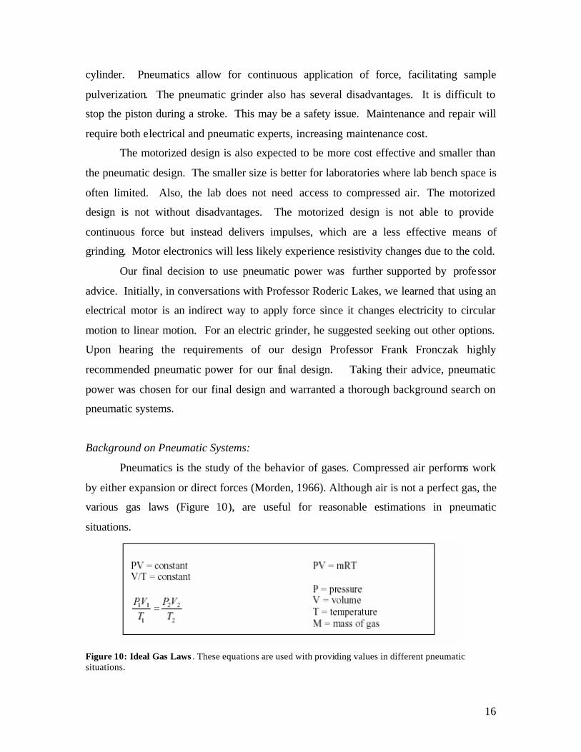
Background on Pneumatic Systems:
Pneumatics is the study of the behavior of gases. Compressed air performs work
by either expansion or direct forces (Morden, 1966). Although air is not a perfect gas, the
various gas laws (Figure 10), are useful for reasonable estimations in pneumatic
situations.
Figure 10: Ideal Gas Laws . These equations are used with providing values in different pneumatic situations.

17
Pneumatic tools operate on compressed air. Hospitals have many uses for
compressed air including pneumatic drills, saws and ventilators.(Jacob and Kumaresh,
2001). Other general purpose pneumatic tools drill, rivet, chip, and caulk. These tools
fall into two main categories: percussive and rotary. Riveting hammers, which fall under
the percussive category, provide between 700 to 3,000 impacts per minute (British
Compressed Air Society, 1955).
Pneumatic tools offer many advantages over mechanical tools. They provide
linear motion without complicated mechanical parts such as gears, cams or shafts. By
varying the air pressure, the applied force can be controlled. This applied force can also
be easily maintained for durations of time. Speed can be controlled by changing valve
and pipe sizes (Morden, 1966). Pneumatic circuits can be developed with many parallels
to electric circuits, allowing for designs with precise control of piston action. An
explanation of va lves common to these circuits can be found in Appendix C.
The primary device for changing compressed air into operation power for tools is
the cylinder. The standard components of a cylinder are the barrel, end covers, piston,
and piston rod. The force generated by the piston is given by the following equation:
F = pA (F = force, p=pressure; A = area of piston).
The simplest pneumatic cylinder is the single-acting type (Figure 11). The
cylinder is fed compressed air from a compressor. Assuming the piston starts in the
upright position, the air expands inside the chamber above the piston forcing the piston
down. The lower chamber of the piston is connected to a vent that allows the air
underneath the piston to exit, decreasing resistance to the moving piston. The piston is
returned by a spring (Pinches and Callear, 1996).
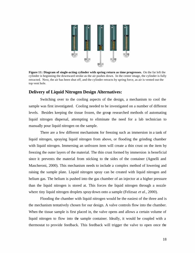
18
Figure 11: Diagram of single-acting cylinder with spring return as time progresses. On the far left the cylinder is beginning the downward stroke as the air pushes down. In the center image, the cylinder is fully retracted. Next, the air has been shut off, and the cylinder retracts by spring force, as air is vented out the top vent hole. Delivery of Liquid Nitrogen Design Alternatives:
Switching over to the cooling aspects of the design, a mechanism to cool the
sample was first investigated. Cooling needed to be investigated on a number of different
levels. Besides keeping the tissue frozen, the group researched methods of automating
liquid nitrogen dispersal, attempting to eliminate the need for a lab technician to
manually pour liquid nitrogen on the sample.
There are a few different mechanisms for freezing such as immersion in a tank of
liquid nitrogen, spraying liquid nitrogen from above, or flooding the grinding chamber
with liquid nitrogen. Immersing an unfrozen item will create a thin crust on the item by
freezing the outer layers of the material. The thin crust formed by immersion is beneficial
since it prevents the material from sticking to the sides of the container (Agnelli and
Mascheroni, 2000). This mechanism needs to include a complex method of lowering and
raising the sample plate. Liquid nitrogen spray can be created with liquid nitrogen and
helium gas. The helium is pushed into the gas chamber of an injector at a higher pressure
than the liquid nitrogen is stored at. This forces the liquid nitrogen through a nozzle
where tiny liquid nitrogen droplets spray down onto a sample (Felizsaz et al., 2000).
Flooding the chamber with liquid nitrogen would be the easiest of the three and is
the mechanism tentatively chosen for our design. A valve controls flow into the chamber.
When the tissue sample is first placed in, the valve opens and allows a certain volume of
liquid nitrogen to flow into the sample container. Ideally, it would be coupled with a
thermostat to provide feedback. This feedback will trigger the valve to open once the
19
temperature reached a certain warmth threshold to re-cool the chamber. Currently, only
two alternatives for liquid nitrogen flow are available in the cryogenics industry: an
expensive, high-flow-rate pump and a pressur ized sealed tank (“Cryocare Report”, 1996).
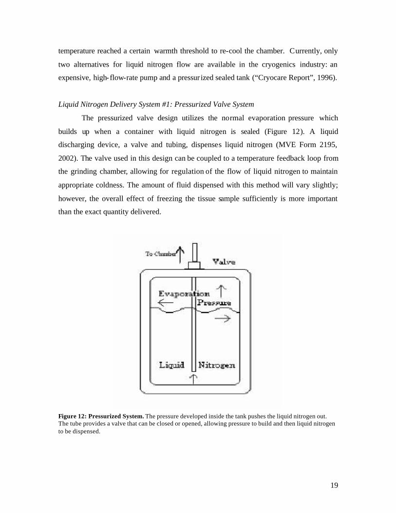
Liquid Nitrogen Delivery System #1: Pressurized Valve System
The pressurized valve design utilizes the normal evaporation pressure which
builds up when a container with liquid nitrogen is sealed (Figure 12). A liquid
discharging device, a valve and tubing, dispenses liquid nitrogen (MVE Form 2195,
2002). The valve used in this design can be coupled to a temperature feedback loop from
the grinding chamber, allowing for regulation of the flow of liquid nitrogen to maintain
appropriate coldness. The amount of fluid dispensed with this method will vary slightly;
however, the overall effect of freezing the tissue sample sufficiently is more important
than the exact quantity delivered.
Figure 12: Pressurized System. The pressure developed inside the tank pushes the liquid nitrogen out. The tube provides a valve that can be closed or opened, allowing pressure to build and then liquid nitrogen to be dispensed.

20
Liquid Nitrogen Delivery System #2: Un-pressurized Pump System
Using a pump to deliver liquid nitrogen to the sample chamber is the second
alternative to consider for this device. A cryogenic pump is defined as a pump that cools
a surface to approximately –255°C in order to produce a very low vacuum with pressures
of about 10-8 mm Hg (“Online Dictionary”, 2002). Pumps currently on the market include
both manual and automated pumps. The manual pumps are simple in design and affix
directly to storage dewars. If a manual pump, such as the one shown in Figure 13, were
incorporated, we would modify the device to automate operation of the pump.
Figure 13: A Manual Pump. This pump is manufactured by Brymill Cryogenic Systems. (http://www.brymill.com/catalog_4_nitro.htm)
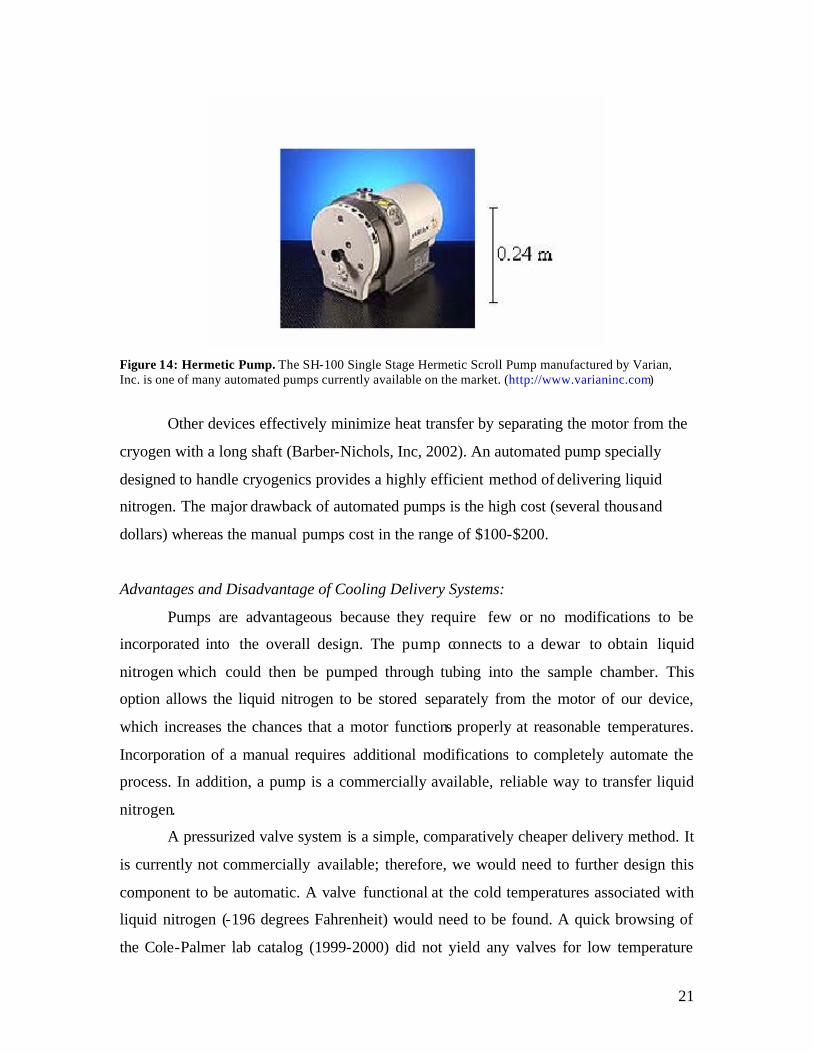
The automated pumps have a hermetic design, which involves both a motor and a
pump. Devices such as the one displayed in Figure 14 minimize the transfer of ambient
heat from the motor to the cryogen using a vacuum system.
21
Figure 14: Hermetic Pump. The SH-100 Single Stage Hermetic Scroll Pump manufactured by Varian, Inc. is one of many automated pumps currently available on the market. (http://www.varianinc.com)
Other devices effectively minimize heat transfer by separating the motor from the
cryogen with a long shaft (Barber-Nichols, Inc, 2002). An automated pump specially
designed to handle cryogenics provides a highly efficient method of delivering liquid
nitrogen. The major drawback of automated pumps is the high cost (several thousand
dollars) whereas the manual pumps cost in the range of $100-$200.
Advantages and Disadvantage of Cooling Delivery Systems:
Pumps are advantageous because they require few or no modifications to be
incorporated into the overall design. The pump connects to a dewar to obtain liquid
nitrogen which could then be pumped through tubing into the sample chamber. This
option allows the liquid nitrogen to be stored separately from the motor of our device,
which increases the chances that a motor functions properly at reasonable temperatures.
Incorporation of a manual requires additional modifications to completely automate the
process. In addition, a pump is a commercially available, reliable way to transfer liquid
nitrogen.
A pressurized valve system is a simple, comparatively cheaper delivery method. It
is currently not commercially available; therefore, we would need to further design this
component to be automatic. A valve functional at the cold temperatures associated with
liquid nitrogen (-196 degrees Fahrenheit) would need to be found. A quick browsing of
the Cole-Palmer lab catalog (1999-2000) did not yield any valves for low temperature

22
cryogenic systems; therefore a more rigorous search would need to be conducted. Also, a
temperature gauge could easily be integrated, thereby keeping the temperature in the
sample-grinding chamber below a temperature threshold during the entire preparation
process. Based on these advantages, we would like to incorporate one into the design,
but based on cost limitations of this project, it is not feasible. Therefore, manual cooling
of the sample was decided to be the best means possible with the resources available.
Sample Chamber Design:
Next, the focus turned to designing a sample chamber that would meet the
temperature requirements. Before the tissue grinding process can begin, all materials that
contact the tissue must be cooled. Pre-cooling and cold storage of the device is
accomplished by either periodic liquid nitrogen application or an additional cooling
system. Adding liquid nitrogen periodically is ideal, therefore different cooling systems
were considered. Two options currently exist: a dependent storage of the device in a
freezer or an independent cooling system. The necessity of a freezer would be a major
drawback; therefore an independent cooling system was incorporated in the sample
chamber design.
When designing our sample chamber, two other requirements besides the
temperature concerns governed our design. The chamber needs to be rounded in shape
to match the grinding head. Also, the chamber should provide a means for sheltering the
sample to minimize the amount of sample spray during grinding. Secondary to these is
the ease of sample collection. Early in the project, two options were considered. One
option uses a hole at the base of the sample chamber, which can be selectively opened to
allow the sample to pass through. The other option inverts the sample chamber, dropping
ground sample into a funnel. When building the prototype, our group did not consider
this design constraint as vital, and was not pursued further. The lab technician needs to
manually place the sample in a test tube, taking them about one minute.
Liquid Nitrogen Volume and Time Testing:
To better understand the temperature limitations as well as amount of pressure
building up in the sample chamber; a testing protocol was created to determine the

23
required volume of liquid nitrogen needed to completely freeze a tissue sample and time
until sample thawing. Each mouse liver tissue sample, 1 cm3 in size, was placed in a
mortar, and a specific volume of liquid nitrogen was poured over the sample. Liquid
nitrogen volumes ranged from 6-20 mL. The time required for the liquid nitrogen to
evaporate, as well as the first sign of sample thawing was recorded. Thawing was
determined by a change in the color of the sample. It was observed that at least 15 mL of
liquid nitrogen was required to completely freeze a sample and the tissue began to thaw
after 5 minutes. Further testing of three repetitions per sample for 15 mL and 20 mL of
liquid nitrogen were completed. Thawing times were averaged. Data and calcula tions
can be found in Appendix D. A one-tailed t-test assuming independent samples was
performed, resulting in a p-value of 0.09, meaning that for a 95% confidence level, the
addition of 15 mL and 20 mL of liquid nitrogen was not statistically significantly
changing thawing time. Therefore, the volume of liquid nitrogen used to freeze a sample
can be in the range of 15-20 mL. These values were then used to do pressure calculations
found in Appendix E.
Chamber Insulation Design Alternatives:
Based on the testing data, a tissue sample stored in the device for any extended
amount of time longer than 5 minutes will being to thaw. To ensure that the sample
remains frozen during the entire grinding process, the device should have an additional
system to keep the tissue frozen. To effectively keep the sample chamber cold, two
insulation designs, an insulated chamber and an additional dry ice insulated chamber
were developed.
Chamber Insulation Design #1: Insulated Chamber
In this simple design, the grinding sample chamber is surrounded by a thick layer
of insulating material (Figure 15). When liquid nitrogen is placed in the sample chamber,
the chamber is cooled, freezing the sample. Because of the insulation, the amount of time
needed for the sample chamber to warm up is lengthened. Depending on the thickness
and properties of the material chosen, the exact time it takes before the sample thaws can
be manipulated.

24
Figure 15: Insulated Grinding Chamber. Insulation is wrapped around the grinding chamber to keep the chamber from warming up as fast.
Chamber Insulation Design #2: Additional Dry Ice Insulated Chamber
In this design, another chamber underneath the grinding chamber is included.
This insulated container holds a dry ice and alcohol mixture which simulates an -80 ° C
freezer, significantly increasing the time the sample chamber is cold enough to keep the
sample frozen.
Figure 14: Dry Ice and Alcohol Bath Insulation Unit. An insulated chamber containing dry ice and alcohol is placed underneath the sample chamber to keep the unit cool.
Evaluation of Insulation Designs:
By simply surrounding the device with insulation, the increased time that the
sample remains cold will not be significant enough. The dry ice and alcohol bath would
drastically improve the time the sample remains frozen. The dry ice system is a more
complex system than the insulation, but not unreasonable. Dry ice and alcohol are
25
common place in many medical and biochemical laboratories. Based on this, the dry ice
and alcohol chamber was chosen for our final design.
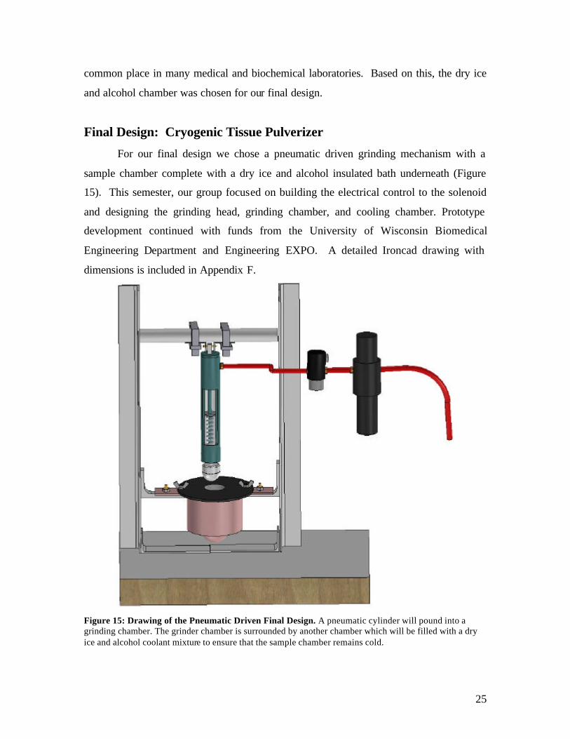
Final Design: Cryogenic Tissue Pulverizer
For our final design we chose a pneumatic driven grinding mechanism with a
sample chamber complete with a dry ice and alcohol insulated bath underneath (Figure
15). This semester, our group focused on building the electrical control to the solenoid
and designing the grinding head, grinding chamber, and cooling chamber. Prototype
development continued with funds from the University of Wisconsin Biomedical
Engineering Department and Engineering EXPO. A detailed Ironcad drawing with
dimensions is included in Appendix F.
Figure 15: Drawing of the Pneumatic Driven Final Design. A pneumatic cylinder will pound into a grinding chamber. The grinder chamber is surrounded by another chamber which will be filled with a dry ice and alcohol coolant mixture to ensure that the sample chamber remains cold.
26
Structural Components
Sample Chamber and Metal Insulating Chamber
Design development of the sample chamber over the past two semesters has
focused on keeping the tissue sample cold during the grinding process while addressing
other client requirements. Initial designs for the sample chamber were minor variations
of the final design. The general design needs to have both a rounded bottom to mimic the
shape of the mortar it is replacing and sides that prevent any sample from escaping from
the chamber during grinding. The chamber itself needs to be removable to facilitate ease
in cleaning between samples. While in use, the sample chamber needs to be securely
attached to prevent its movement during grinding.
Constructed from stainless steel, the final design of the sample chamber features a
thin, wide rim connected to a hollow cylinder and a pipe cap. The wide rim has two
holes that allow the sample chamber to be placed over two screws of the metal insulating
chamber and tightened in place with wing nuts. The height of the hollow cylinder
(approximately three inches) adequately prevents the sample from exiting the chamber
during grinding. The pipe cap is nearly hemispherical and forms the rounded bottom of
the sample chamber.
The sample chamber fits inside the metal insulating chamber, and the wide rim
rests on top of the insulating chamber. The space between the walls of the metal
insulating chamber and the sample chamber provides room for a dry ice and alcohol
mixture that further insulates the sample during the entire grinding process in addition to
cooling from the liquid nitrogen (Figure 16). The metal insulating chamber is formed
from a larger hollow cylinder and two thin rectangles that allow the chamber to be
attached to the main structure of the device. Mounted on each thin rectangle is a screw to
provide a point of attachment for the sample chamber. Each rectangle also has a lateral
hole to allow for a second set of screw attachments to the L-brackets that support the
insulating chamber. The bottom of the metal insulating chamber features a smaller
hemispherical dome that mirrors the bottom of the sample chamber in order to allow the
dry ice and alcohol mixture to fully surround and insulate the bottom of the sample
chamber. AutoCAD drawings of the sample chamber can be found in Appendix G.

27
Figure 16: Ironcad Drawings of Sample and Cooling Chamber. A cooling chamber surrounds the inner grinding chamber. The cooling chamber contains a dry ice and alcohol bath.
Grinding head
The grinding head was machined from stainless steel and its shape was
determined to most closely match the contour of the inside curvature of the pipe cap that
forms bottom of the sample chamber. The radius of curvature for the grinding head was
chosen to be the same as that of the pipe cap to maximize the contact surface area during
grinding. To firmly attach the grinding head to the pneumatic cylinder, the grinding head
features a threaded hole the same size as the screw at the end of the pneumatic cylinder.
The grinding head can be easily cleaned due to the incorporation of a threaded cylinder
attachment. AutoCAD drawing of the grinding head are in Appendix G.
Stand
The design of the stand for the device was implemented with three basic
objectives: withstand linear force exerted by cylinder, hold cylinder upright, and
incorporate simple component attachment. The stand must withstand the linear force of
the cylinder. The design is rectangular, incorporating four components: top, bottom, and
two sides. The top and bottom of the stand withstands three-point bending, while the two
sides withstand tensile force. The amount of force exerted by the cylinder is determined
by the amount of air pressure applied. The average expected lab air pressure produced by
a building’s HVAC system is 100 psi (Fronczak, 2002). Estimating a bore diameter of
one square inch, to simplify calculations, the stand is able to respond with a 100 pounds
force.
The other two main concerns are easily addressed by specializing design for linear
force. To hold the cylinder upright, the base was chosen as a plane. The plane provides
enough material on all sides to prevent the cylinder from falling over. Simple attachment
of components is achieved by plastic ties wrapped through holes in the side supports.

28
The local hardware store was the best place for materials. Considerations for part
selection include cleaning efficacy, durability, and strength.
A steel rod acts as the top of the stand. The rod simplifies attachment of the
cylinder mount provides adequate strength against the three-point bending. The pivot
mount, a Bimba bracket kit, was chosen to minimize buckling. The permanent pivot
mount is carefully aligned over the entrance to the grinding chamber to minimize
buckling in the direction the pivot did not swing. Since a pivot mount reduced buckling
in only one plane, a ball and socket joint would have been preferable.
A plane of wood serves as the stand base. It is relatively lightweight, easy to
attach bolts to; however, wood is not easily cleaned, especially the combination of
unfinished wood and animal tissues. For this reason, a piece of sheet metal was chosen to
cover the plane of wood. The wood also holds the rest of the stand upright. The sides of
the stand are two steel posts with holes down the side. They are strong enough to
withstand force produced by the cylinder, easily cleaned, and allow easy attachment of
other components. All components are easily bolted together to provide a secure
structure for the cylinder, sample chamber, cooling chamber, solenoid, and upright
regulator. AutoCAD drawings of the stand are in Appendix G.
Stand Strength: Three-Point Bending Analysis
The cylinder is mounted by a pivot joint at one end. This pivot joint is connected
to rod and support bars. For this situation, three-point bending is a concern. The cylinder
will deliver 100 pounds of force to the tissue sample and to the mounting hardware. The
rod must withstand bending, and the support bars must withstand the tension applied. The
equations for three-point bending are shown below (see Equations 1.1).
(Equation 1.1) I
My=σ
where M = moment; y = distance from neutral axis; I = inertia; and σ = maximum stress. (Equation 1.2) εσ E= where σ = maximum stress; E = elastic modulus; and ε = strain.
(Equation 1.3) 4*)4
( rIπ
=

29
where I = inertia; r = radius.
The maximum stress for a particular material is often known from previous stress-
strain experiments involving graphs of equation 1.2. Using this maximum stress of the
material and comparing the value to the maximum stress generated from bending (see
Equation 1.3), we determine if the material is suitable or if the dimensions for the
material are suitable. A new material may offer a stronger alternative; however, if more
strength is needed from the same material, altering the dimensions of the material to
increase the distance from the neutral axis will also increase maximum stress allowed
prior to failure.
Pneumatic Components of Final Design:
Pneumatic Cylinder:
According to the Bimba cylinder catalog, a 1-1/16” bore air cylinder will provide
a force of approximately 0.9 times the air line pressure. With lab pressure varying
between 80 – 120 psi, the cylinder provides 72 – 108 lbs of force. This value will be
stabilized with a regulator.
After the bore size is selected, there are many Bimba cylinders to choose from.
Following the advice of Professor Frank Fronczak, we chose a single acting disposable
cylinder (Figure 17). The spring operated return stroke allows the cylinder to retract
without the use of the air supply. Disposable cylinders are inexpensive, light duty
cylinders that cannot be serviced if seals deteriorate.
Figure 17: Bimba Single Acting Pneumatic Cylinder. Shown with screw-in brass fitting. Digital camera image of actual purchased 1-1/16” bore cylinder. (11” in length).

30
We chose a 4” stroke length for the cylinder. Only the last 1” of this stroke length
will be used since the cylinder needs only to clear the maximum sample height. Also,
with the appropriate valve cycling pattern, the cylinder will not fully retract, preventing
sample loss, since the grinding head will remain deep within the grinding chamber edges.
A circular rod shape was chosen for flexibility in future modifications. The
circular rod shape leaves open the possibility for the future design of a twisting motion in
the rod to facilitate shear forces to grind the sample.
The additional option “N” (low temperature seals and lubrication), was added to
our cylinder. At cold temperatures the cylinder’s life is shortened due to the changing
consistency of lubricants, overstressed metal, and damaged and brittle seals (Korane,
2002). The low temperature seals extend the operating range of our cylinder to
encompass -40° to 200°F for only $0.80.
We discarded the option of ordering an attached solenoid valve to reduce cost and
allow more flexibility in our design. Our final cylinder order consists of a 094-PN
cylinder special ordered, pivot brackets (mounting), and piston rod clevis (mounting)
from Price Engineering, a Bimba Distributor.
Regulator/Filter:
To implement the pneumatic system and ensure proper maintenance of moving
parts, a filter/regulator is incorporated (Figure 18). The air pressure from the HVAC
system installed within a building is expected to be near 120 psi. The pressure will
fluctuate due to the number of users on the HVAC system. A regulator is necessary to
control these pressure fluctuations and prevent the pressure from exceeding the chosen
level set by the user. The regulated pressure drives the cylinder in regular intervals. For
our design, we selected a filter coup led with a regulator.
The other component of the combination, the filter, removes debris and liquid
from the pressurized air. Unfiltered debris and liquid results in excess wear on the
cylinder, limiting its lifetime. Vertical placement is essential for proper filter function.

31
Figure 18: The Filter/Regulator. This filters debris and liquid while regulating air flow into the pneumatic cylinder. Digital camera image of Parker regulator. (9” in height)
Solenoid Valve:
Cylinder control is established through controlling the air line. This is performed
with a simple 3-way, 2-position inline valve (Figure 19). The “3 way” describes the 3
ports for the valve including: inlet, vent, and out (to cylinder). Only 2 ports are connected
to the air line system, since the cylinder has a spring operated return. The third port is
left open as a vent to release air on the cylinder's return stroke. The solenoid allows the
design to be electrically controlled, turning electrical energy into mechanical movement
of the valve. Energizing the solenoid causes the valve to open, allowing air flow to the
cylinder and extending the rod to pound. Upon de-energizing, the valve opens to vent air
to the environment, allowing the spring retraction of the cylinder’s rod to reset the stroke.
Figure 19: Solenoid Valve. The solenoid valve controls the cylinder motion during grinding. Digital camera image of purchased Humphrey solenoid valve. (3” in height).
On the advice of an engineer at Price Engineering, we selected the 31-E1-120-
VAC solenoid valve. The 1/8” port allows attachment to our cylinder’s air tubing without
size adaptors. The wires extending from the solenoid valve are connected to an electrical
wall socket to provide the electrical source. A timing circuit will control this electrical
source (see Electrical section).

32
Additional Accessories:
From Price Engineering we ordered 5 push- in fittings and 10 feet of air tubing to
connect all of the pneumatic parts together. The fittings have male pipe threads that fit
directly into the ports of the cylinder, solenoid valve, and regulator. The air tubing is
pushed into the fitting and instantly locks into the fitting, providing a superior air seal.
Teflon tape was used to seal the threading on the fittings to ensure minimal air loss.
Electronic Control of Final Design:
Main Timing Circuit
The main timing circuit is the original creator of the desired ON/OFF signal. Our
circuit, based from designs by W.D. Phillips, is composed of the following components:
• 555 timer: 8 pin LM555
• 2 capacitors: 47 uF and 1 uF
• 2 resistors: 1 kΩ and 680 Ω
• potentiometer: 5 MΩ
• light-emitting diode (LED)
• voltage source 9 V
The circuit was built for initial testing on a protoboard (Figure 20). The
potentiometer, a variable resistor, was added to allow the most variability. This ON time
eventually corresponds to the time solenoid valve is open. Resistor and capacitor values
were chosen to provide approximately a frequency of 1 Hz, translated to the pneumatic
system to 1 pound/second.
The following equations (Phillips, 2003) show the controlling variables:
CRRf
*)2(44.1
21 +=
CRRONtime *)(*69.0 21 +=
CROFFtime *)(*69.0 2=
OFFtimeONtime
DutyCycle =
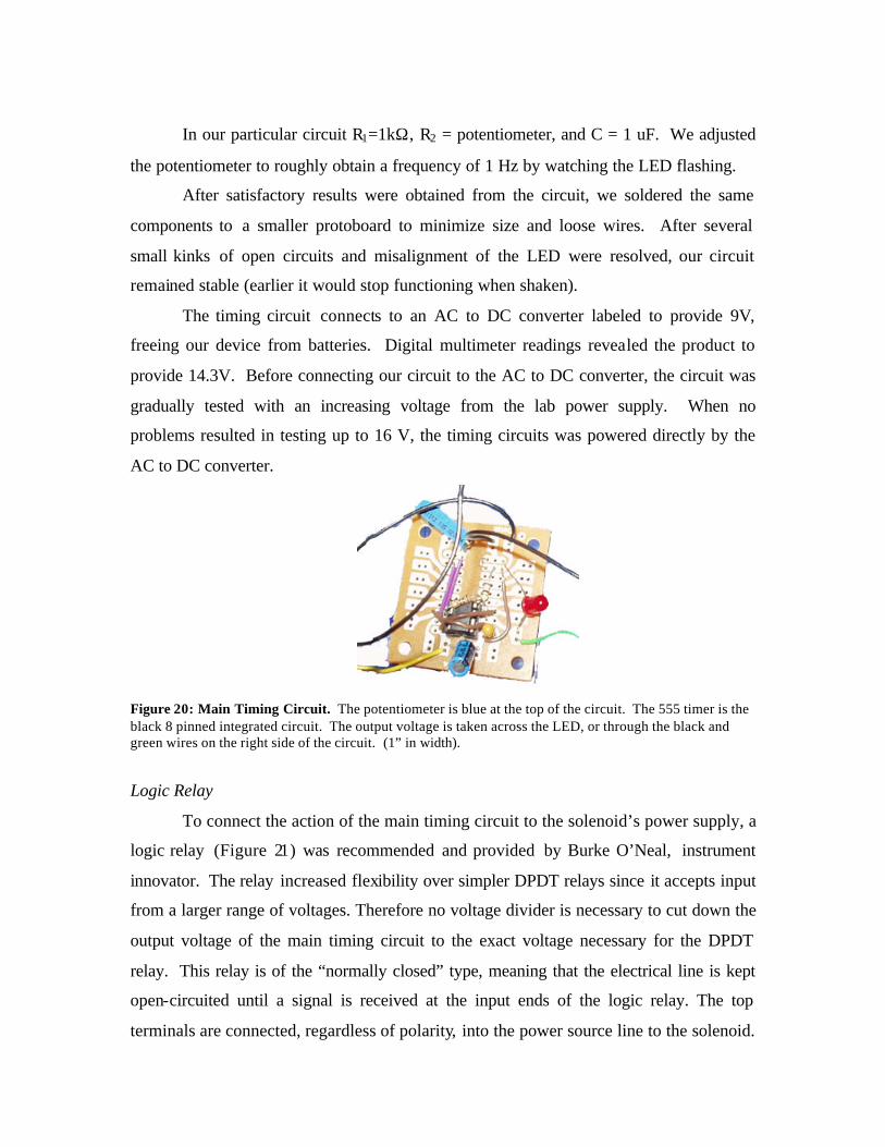
In our particular circuit R1=1kΩ, R2 = potentiometer, and C = 1 uF. We adjusted
the potentiometer to roughly obtain a frequency of 1 Hz by watching the LED flashing.
After satisfactory results were obtained from the circuit, we soldered the same
components to a smaller protoboard to minimize size and loose wires. After several
small kinks of open circuits and misalignment of the LED were resolved, our circuit
remained stable (earlier it would stop functioning when shaken).
The timing circuit connects to an AC to DC converter labeled to provide 9V,
freeing our device from batteries. Digital multimeter readings revealed the product to
provide 14.3V. Before connecting our circuit to the AC to DC converter, the circuit was
gradually tested with an increasing voltage from the lab power supply. When no
problems resulted in testing up to 16 V, the timing circuits was powered directly by the
AC to DC converter.
Figure 20: Main Timing Circuit. The potentiometer is blue at the top of the circuit. The 555 timer is the black 8 pinned integrated circuit. The output voltage is taken across the LED, or through the black and green wires on the right side of the circuit. (1” in width).
Logic Relay
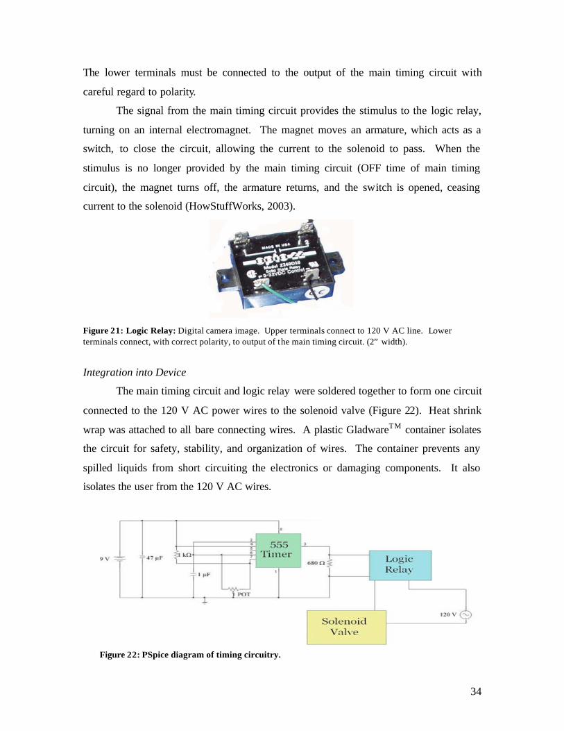
To connect the action of the main timing circuit to the solenoid’s power supply, a
logic relay (Figure 21) was recommended and provided by Burke O’Neal, instrument
innovator. The relay increased flexibility over simpler DPDT relays since it accepts input
from a larger range of voltages. Therefore no voltage divider is necessary to cut down the
output voltage of the main timing circuit to the exact voltage necessary for the DPDT
relay. This relay is of the “normally closed” type, meaning that the electrical line is kept
open-circuited until a signal is received at the input ends of the logic relay. The top
terminals are connected, regardless of polarity, into the power source line to the solenoid.
34
The lower terminals must be connected to the output of the main timing circuit with
careful regard to polarity.
The signal from the main timing circuit provides the stimulus to the logic relay,
turning on an internal electromagnet. The magnet moves an armature, which acts as a
switch, to close the circuit, allowing the current to the solenoid to pass. When the
stimulus is no longer provided by the main timing circuit (OFF time of main timing
circuit), the magnet turns off, the armature returns, and the switch is opened, ceasing
current to the solenoid (HowStuffWorks, 2003).
Figure 21: Logic Relay: Digital camera image. Upper terminals connect to 120 V AC line. Lower terminals connect, with correct polarity, to output of the main timing circuit. (2” width).
Integration into Device
The main timing circuit and logic relay were soldered together to form one circuit
connected to the 120 V AC power wires to the solenoid valve (Figure 22). Heat shrink
wrap was attached to all bare connecting wires. A plastic GladwareTM container isolates
the circuit for safety, stability, and organization of wires. The container prevents any
spilled liquids from short circuiting the electronics or damaging components. It also
isolates the user from the 120 V AC wires.
Figure 22: PSpice diagram of timing circuitry.
35
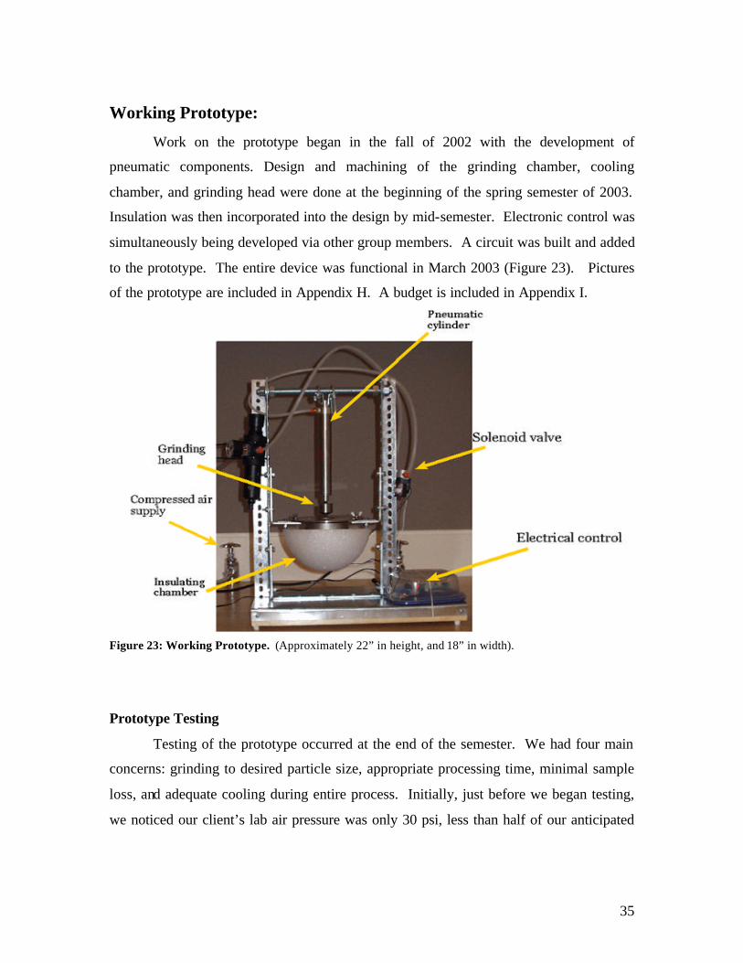
Working Prototype:
Work on the prototype began in the fall of 2002 with the development of
pneumatic components. Design and machining of the grinding chamber, cooling
chamber, and grinding head were done at the beginning of the spring semester of 2003.
Insulation was then incorporated into the design by mid-semester. Electronic control was
simultaneously being developed via other group members. A circuit was built and added
to the prototype. The entire device was functional in March 2003 (Figure 23). Pictures
of the prototype are included in Appendix H. A budget is included in Appendix I.
Figure 23: Working Prototype. (Approximately 22” in height, and 18” in width).
Prototype Testing
Testing of the prototype occurred at the end of the semester. We had four main
concerns: grinding to desired particle size, appropriate processing time, minimal sample
loss, and adequate cooling during entire process. Initially, just before we began testing,
we noticed our client’s lab air pressure was only 30 psi, less than half of our anticipated

36
80 – 100 psi. This variable may have affected our results. Despite this altercation, we
continued testing the device on mouse liver tissue.
Testing continued with the supplies (tissue, dry ice, alcohol, liquid nitrogen,
safety gloves, safety glasses, and a scraper) provided by our client. As were limited to 2
mouse liver tissue samples, we decided to discard plans to compare grinding results
between manual and automated grinding. There was also disagreement between our
clients on whether a protein assay was appropriate for quantization of grinding. Dr. Jeff
Ross suggested homogenizing the samples and then performing the protein assay to
determine how much protein was released from the cells. Charles Tessier, the graduate
student who works most often with the tissue grinding, opposed the test. He argued that
the homogenization would equal out the grinding results and did not regard a protein
assay as an effective judge of particle size. With only 2 samples, no statistical
comparisons were possible since we would be unable to estimate standard deviations or
means with only 1 sample per treatment. The group collectively decided that submitting
the 2 tissue samples to automated grinding would be more worthwhile.
Any similar future testing of particle size would be most effectively determined
with either a microscope or fine mesh in a freezer room or outside on a day below
freezing to prevent sample melting. Previous testing revealed tissue to melt very quickly
at room temperature, making such tests difficult.
After we began grinding, we noticed the time required for the whole process was
much shorter than manual preparation. Judging by the particle size and rate of change
from large to small particles per unit time, we concluded a grinding period of 1 minute
was sufficient. A second sample was tested to check for consistent and repeatable
grinding.
The particle sizes produced by our device had a greater range than manual
preparation. The sizes of the particles ranged from one millimeter to approximately ten
microns. Professional observation by Charles Tessier, who has processed many samples
manually, rated the grinding efficiency as 80% acceptable. This rating shows room for
improvement. To better grind the sample, a shaking plate may be implemented into the
device to redistribute and center the sample directly underneath the grinding head. A
37
turning grinding head would contribute shearing forces to grind the remaining larger
tissue pieces.
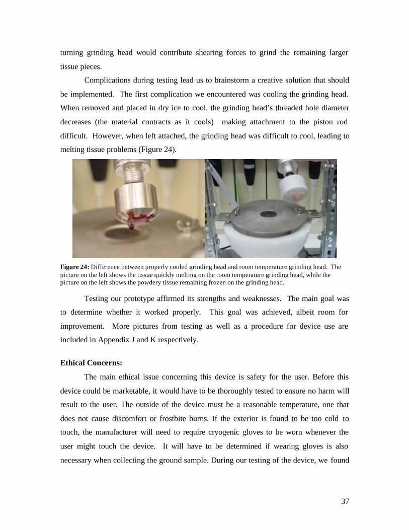
Complications during testing lead us to brainstorm a creative solution that should
be implemented. The first complication we encountered was cooling the grinding head.
When removed and placed in dry ice to cool, the grinding head’s threaded hole diameter
decreases (the material contracts as it cools) making attachment to the piston rod
difficult. However, when left attached, the grinding head was difficult to cool, leading to
melting tissue problems (Figure 24).
Figure 24: Difference between properly cooled grinding head and room temperature grinding head. The picture on the left shows the tissue quickly melting on the room temperature grinding head, while the picture on the left shows the powdery tissue remaining frozen on the grinding head.
Testing our prototype affirmed its strengths and weaknesses. The main goal was
to determine whether it worked properly. This goal was achieved, albeit room for
improvement. More pictures from testing as well as a procedure for device use are
included in Appendix J and K respectively.
Ethical Concerns:
The main ethical issue concerning this device is safety for the user. Before this
device could be marketable, it would have to be thoroughly tested to ensure no harm will
result to the user. The outside of the device must be a reasonable temperature, one that
does not cause discomfort or frostbite burns. If the exterior is found to be too cold to
touch, the manufacturer will need to require cryogenic gloves to be worn whenever the
user might touch the device. It will have to be determined if wearing gloves is also
necessary when collecting the ground sample. During our testing of the device, we found

38
touching of the exterior metal to not result in any user discomfort. Warning labels for the
extremely cold temperatures inside the chamber may be required.
In addition to safety in handling the device, another concern is how often the user
will need to handle liquid nitrogen directly during the entire process. The amount of
handling or transfer of liquid nitrogen should be minimized in conjunction with this
device in order to prevent possible burns from the cryogen. With the current prototype,
the user must transfer liquid nitrogen to the device’s sample chamber for each sample to
be processed.
While safety is the major ethical issue with this device, the cleaning and
sterilization of the device is also a concern. The method chosen for disinfecting the
sample chamber between successive samples processed must be reliable and efficient in
order to prevent contamination of the next sample inserted into the device. The sample
chamber is made of stainless steel, so it can be cleaned thoroughly with an autoclave.
Also, this procedure should be well documented so any user would be able to follow the
instructions and disinfect the sample grinding area between samples.
Another possible ethics issue with the device may occur if the device falls into the
wrong hands. Certain individuals may want to sample tissues in order to design
destructive carcinogens or proliferate disease. This is not the scope of the tissue sampler
demographic. We encourage the use of the tissue preparation device to provide a resource
for researchers trying to eliminate cancer. Any use of the device for destructive means is
discouraged.
Our project does not directly involve animal care, although we do use mouse
tissue samples provided by our client. If our client’s research advances to human
subjects, different protocol will need to be followed. Although we are not personally in
charge of ethical animal care, as members of a design team, we must still assure proper
treatment and protocol is followed in sacrificing the mice. Verifying that our client has
consulted the Research Animal Resources Center (RARC) is an important part of ethical
testing, since tissue is collected from the mice liver. Since mice tissue could be a
biohazard, we carefully consulted with our client before safely labeling and disposing of
the ground mouse tissue.

39
Regulation Concerns:
The Center for Biologics Evaluation and Research (CBER) regulates medical
devices that collect, process, test, and manufacture blood, blood components, and cellular
products. The CBER has developed The Device Action Plan of 1997 and implemented
this plan on April 26, 1999. This plan helps to ensure that the policies of the CBER are
consistent with those of the Food and Drug Administration’s (FDA) Center for Devices
and Radiological Health (CDRH), the Office of Regulatory Affairs (ORA) and the Office
of Chief Council (OCC). The CBER website has many links to the FDA (CBER, 2002)
Currently the FDA has three classes of regulation for medical devices.
Information our group found relevant is included in Appendix L. Class III are the most
regulated and are typically devices, which either support or sustain human life or have an
unreasonable high risk of illness or injury associated with them. These devices all require
pre-market approval. Class II devices are subject to certain FDA standards. Class II
devices are subject to only general controls (FDA, 2002).
New devices that cannot be compared to an equivalent existing device of either
Class I or II will be classified as Class III. This classification will remain until a
Premarket Approval (PMA), Product Development Protocol (PDP), or a petition to the
FDA to reclassify the device as Class I or II is submitted. This means that we will need to
initially submit a PMA on our device and wait to see if the FDA determines “substantial
equivalence” with another preexisting device. If they categorize our device as Class I or
II, then we do not need to apply for approval. If they categorize our device as a Class III
(“new” device) we will need to either petition the FDA to reclassify it, or wait for further
classification (FDA, 2002).
Our device seems to fit between two categories: “Clinical Chemistry and Clinical
Toxicology-General purpose laboratory equipment labeled or promoted for a specific
medical use” and “Hematology and Pathology Devices – Tissue processing equipment.”
The chemistry categorization is Class I, and the tissue-processing category is exempt
from PMA forms (FDA, 2002). This suggests we will not have difficulty obtaining FDA
approval for our device.
Future Concerns and Direction of the Project:
40
As all four team members are graduating May 2003, our work on the device will
cease. Testing revealed several key developments that will greatly improve our device.
Due to time constraints we are not able to add them. Any future student group interested
in prototype development should consider the following concerns and suggestions for
future development.
Grinding:
After testing our system at 30 psi, our sample was rated 80% acceptable. Several
variables can be changed to improve grinding to a higher acceptance rate. Running the
device with air pressure at 80 psi will more than double the force applied to the sample.
If higher air pressure is not available, several alternatives exist. A larger cylinder bore
size will increase force applied to sample. A modification to rotate the grinding head will
add shearing forces to the grinding, proven by earlier testing to create finer granules.
Vibrations added to the sample chamber will help distribute the larger tissue pieces for
better grinding.
Cooling:
As mentioned in testing, the current procedure for cooling the grinding head is
insufficient. To remedy this problem, a switch bypass should be added to the timer
circuit to enable the user to flip a switch to submerge the grinding head into the sample
chamber for a prolonged period. The switch directly connects the solenoid to the AC
power line, avoiding the timing pattern and instead providing constant current. This
current holds the solenoid valve open, allowing constant airflow to the pneumatic
cylinder. With the pneumatic cylinder piston fully extended, the grinding head is deep
within the sample chamber, ideal for immersion of the grinding head in liquid nitrogen.
This method effectively cools the head without complications associated with reattaching
a pre-cooled grinding head.
Closer fitting polystyrene will improve insulation. While we were limited to
removable insulation for ease of cleaning the device, future development should include
finding a tighter fitting insulation. Other possibilities include quick drying liquid
41
polystyrene that can be painted on. If this option is pursued, the design must ensure that
the metal can be autoclaved for proper sanitation.
Additionally a simple circuit with a thermocouple, comparator and sound alarm
should be installed to alert the lab technician if the device temperature rises above
freezing. The thermocouple could be either submerged in the dry ice bath or integrated
into the metal. This addition is an important and inexpensive safety measure.
Ergonomics:
Several minor modifications should be made to the grinding and cooling
chambers to simplify assembly and cleaning. The lateral holes for the wing-nuts are
placed extremely close to the attachment creating too tight of a sample chamber fit. This
attachment site needs to be moved out laterally. A similar wing-nut attachment site
should be adapted to the cooling chamber as presently a wrench is required for loosening
the chamber. The current design does not allow easy emptying of the dry ice and alcohol
bath. Wing-nuts at the site allow removal and assembly to occur without tools.
Conclusions:
After 3 semesters of work we have achieved an 80% grinding efficiency under
limited conditions of 30 psi. Although the automation is not currently as effective as
manual grinding, the process cuts grinding time remarkably to 1 minute. At the current
stage, our device at least provides the initial preparation which will lead to proper
consistency with a small additional amount of manual work. Our device provides a much
more stable grinder than the fragile ceramic mortar and pestle of our client.
Pneumatic power and baths of liquid nitrogen and dry ice/alcohol do appear to be
effective design choices. All recommended changes to the design are merely additions
and not changes to the basic principles we have devised. The stand and machined
chambers remain solid through the pounds of the cylinder and harsh cryogenic
conditions. Our circuit is reliable, isolated, and safe. Provided with the procedure for
operation, our client should be readily able to grind and freeze his tissue samples in our
device.

42
References and Resources
Agnelli, M. and Mascheroni, R. 2001. Cryomechanical freezing. A model for the heat transfer process. Journal of Food Engineering 27: 263 – 270. Asymptote. Asymptote Cool Guide to Cryopreservation. 13 March 2002. http://www.asymptote.co.uk/process/cryo/cryoguide/report/storage.htm>. Barber-Nichols, Inc. Apr 26, 2002. http://www.barber-nichols.com/cryogenic.htm. BioCold Scientific. Laboratory Grade Freezers. 11 March 2002. <http://www.biocoldscientific.com/catalog/bc38.html>. British Compressed Air Society. “B.C.A.S. Handbook of Pneumatic Equipment.” British Compressed Air Society. 1955. Burgess, A. Biocore Lab Instructor, Personal Communication 2/21/02. CBER. “CBER Devices.” May 05, 2002. http://www.fda.gov/cber/devices.htm Cole-Palmer Instrument Company. Lab Catalog: 1999-2000. CryoCare Report No. 7.” (April 1996). CryoCare Foundation. 22 Apr 2002.
http://www.cryocare.org/ccrpt7.html. FDA. “Device Advice-Device Classification Panels.” May 05, 2002.
http://www.fda.gov/cdrh/devadvice/3131.html. Felisaz, F., Steinmann, R., Thompson, A., and Stojanoff, V. 2000. Liquid nitrogen cryospray for biological applications. Physica B. 284 – 288: 2074 – 2048. Flynn, T. 1997. Cryogenic Engineering. Marcel Dekker, Inc. New York, NY. “How Relays Work.” How Stuff Works. May 4, 2003. http://electronics.howstuffworks.com/relay.htm Humphrey Technical Library. 31E1/41E1 Mini-Myte Solenoid Valves. Oct 31, 1997. Ingersoll Rand. “IR Air Solutions Group.” May 3, 2002.
<http://www.air.ingersoll- rand.com>. Jacob R. and Kumaresh V. “Medical Grade Compressed Air.” World Federation of Societies of Anaesthesiologists. 2001. < http://www.nda.ox.ac.uk/wfsa/html/u13/u1302_01.htm> Jet Pulverizer Company. How Jet Pulverizers Operate. 11 March 2002. <http://www.jetpul.com/mequip/milloper.htm>. K3PGP Experimenter’s Corner. Cryogenic Cooling of Laser Diodes. 2 Feb 2002. http:/www.qsl.net/k3pgp/construction/cryolaser/cryolaser.htm.

43
Korane, Kenneth. “Maximizing Cylinder Performance.” Bimba Manufacturing Company.
www.bimba.com/techctr/tb052199b.htm LabGlass Products. LG-10650 Tissue Grinder. 10 March 2002. <http://www.lab- glass.com/html/nf/HMGN-LG-10650.html>. Linkam Heating. Heating and Freezing Stages for Optical Microscopy and Precision Temperature. 13 March 2002. <http://www.linkam.co.uk>. “Liquid Nitrogen: Safety Guidance for Oncology Staff.” University of Edinburgh, Department
of Oncology. 21 Oct 2002. http://www.onc.ed.ac.uk/liquidnitrogen.htm MacNeil, K. “Risk Assessment: Handling, Transportation and storage of liquid nitrogen and
other cryogenic material.” Bristol University, School of Chemistry. 8 Apr 2002. http://www.chm.bris.ac.uk/safety/lnitcry.htm
Meyer, S. Biospec Products Incorporated. Retrieved February 20, 2002. <http://www.biospec.com/index.html>. Minnesota Valley Engineering (MVE) Cyrogenics. Form 2195: Liquid Discharging Device
Installing and Operating Instructions. Received April 30, 2002. Morden, S. “Principles and Theory of Pneumatics.” Trade & Technical Press Ltd. England. 1966. “Online Dictionary.” Harcourt, Inc. 26 Apr 2002.
http://www.harcourt.com/dictionary/def/2/6/1/0/2610600.html “Periodic Table of Elements: Nitrogen.” Environmental, Chemistry and Hazardous Materials
Information and Resources. 8 Apr 2002. http://environmentalchemistry.com/yogi/periodic/N.html
"Physics Van Outreach Program." University of Illinois Physics Department. 2 Feb 2002. http://van.hep.uiuc.edu/van/qa/section/Solids_Liquids_and_Gases/Liquids/981741182.htm. Pinches, M. and Callear, B. “Power Pneumatics.” Prentice Hall. London. 1996. Seetharam, R. and Sharma, S., eds. 1991. Purification and Analysis of Recombinant Proteins. Marcel Dekker, Inc, New York. SPI Supplies. SPI Liquid Nitrogen Dewars & Accessories - Liquid nitrogen withdrawal devices. 11 March 2002. <http://www.2spi.com/catalog/instruments/liquid-nitrogen-withdrawal- devices.html>. Univerisity of Illinois Physics Department. Physics Van Outreach Program. 2 Feb 2002. http://van.hep.uiuc.edu/van/qa/section/Solids_Liquids_and_Gases/Liquids/9817 41182.htm.

44
W.D. Phillips. “Design Electronics – 555 timer.” Doctronics. May 4, 2003. http://www.doctronics.co.uk/555.htm Acknowledgements Dr. Jeff Ross – client, testing advice, testing supplies Charles Tessier – client, testing advice, testing supplies Paul Thompson – general advising Burke O’Neal – logic relay assistance Bill Hagquist – machine shop and AutoCAD expertise Prof. Frank Fronczak – pneumatic expertise
45
Appendix A -PDS
Tissue Sample Preparation Device for Biochemical Analysis Version 7 – May 5, 2003
Team Members: Sara Alford Christine Koranda Carla Maas Ryan Roth Client: Jeff Ross and Charles Tessier
UW – Medical School Department of Oncology
Advisor: Paul Thompson
Function: The device will grind a frozen tissue sample into a fine powder, replacing the manual mortar and pestle grinding technique currently used. It will also include a cooling method using liquid nitrogen keep the tissue frozen. The sample should be easily collected after grinding. Client Requirements:
• Sample and tools used must be kept cold at all times during the process • Must salvage as much of tissue sample as possible • Processing time should not exceed that for manual preparation (approximately – 15 minutes) • Device to be used 30 – 40 sample/day • Grind tissue to the consistency of powdered sugar (10µm diameter granules) • No cross sample contamination
Design requirement: 1. Physical and Operational Characteristics
a. Performance requirements: Tissue should be easily inserted into the device. After gr inding completion, tissue sample should be removed and grinding area cleaned before the next sample. Device will be in operation 3 – 5 hours per day. On average the device may have to be turned on 1 -3 times per day. It should be able to grind a soft tissue sample of a maximum sample size of 8 cm3 (2 x 2 x 2 cm). The tissue should remain frozen completely through the grinding experiment.
b. Safety: Liquid nitrogen should be contained to avoid possible contact with skin and clothing. Instrument should be insulated to prevent skin burns. Cryogenic gloves and safety glasses may be required for the use of the device. A means to vent pressure should be included to avoid build up and possible explosion.

46
c. Accuracy and Reliability: Technique should grind sample to a powdered sugar (10 µm diameter granules) consistency. The device should provide an optimal means of sample collection.
d. Life in Service: The device should last 5-10 years with proper handling and maintenance. Around 30-40 samples could be analyzed daily.
e. Operating Environment: Device would function in a normal room temperature (approximately 20°C) biochemistry laboratory. An alternative to laboratory bench storage may be storing the entire device or certain components in a -20° C or -80° C freezer. The interior wall be exposed to extremely cold (-196° C) temperatures. The exterior may be exposed to freezer condition (-20° or -80° C). The device will be handled by a laboratory technician.
f. Ergonomics: The sample should be easily inserted. The user’s hand should not be subjected to a cold temperature during sample insertion. There should be a method for easy refill of the desired coolant (dry ice and alcohol).
g. Size: The device should fit on a laboratory bench with a maximum volume of 0.9x0.61x0.61 m (3x2x2 ft).
h. Materials: Only materials that can withstand cold temperatures can be used (fcc metals such as Nickel, Aluminum, Stainless steel 18-8, Copper). Regular glass and plastics should not be used.
i. Cleaning: Any components of the device that come in contact with the sample should be removable for ease in cleaning and disinfecting (soap and water).
2. Production Characteristics:
a. Quantity: One prototype will be constructed. b. Target Product Cost: If a pathology lab were to purchase the device, a
reasonable range would be $5000-20,000. For our client’s biochemistry laboratory, a reasonable cost for the prototype is $1,000 – 1,500. 3. Miscellaneous
a. Standards and Specifications: Premarket approval by the FDA will be required.
b. Competition: i. Polytron system – a homogenizer that operates at room temperature to
grind up sample. ii. Biospec BeadBeater – uses glass or stainless-steel balls to break apart
sample, operates at room temperature. iii. Biospec Cryogenic Pulverizer – uses hammer to crush pre-frozen
sample in mortar. iv. Jet Pulverizer – use air pressure to pulverize sample.

47
Appendix B – Initial Testing Pictures Figure 1B: From upper left clockwise. (1) Pouring liquid nitrogen, (2) grinding with funnel, (3) Beads, (4) Tight fitting container, (5) Ground tissue in mortar, (6) Shearing force with spatula.
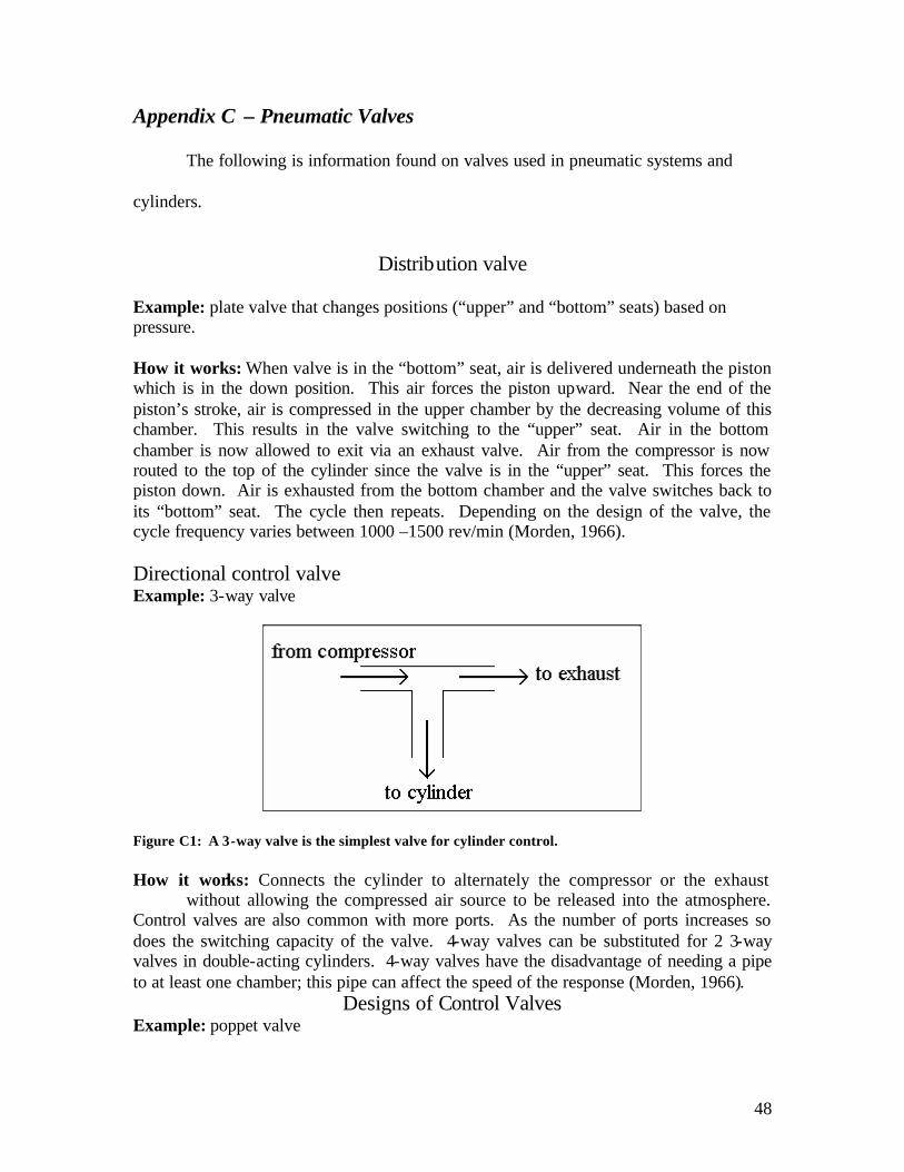
48
Appendix C – Pneumatic Valves
The following is information found on valves used in pneumatic systems and
cylinders.
Distribution valve
Example: plate valve that changes positions (“upper” and “bottom” seats) based on pressure. How it works: When valve is in the “bottom” seat, air is delivered underneath the piston which is in the down position. This air forces the piston upward. Near the end of the piston’s stroke, air is compressed in the upper chamber by the decreasing volume of this chamber. This results in the valve switching to the “upper” seat. Air in the bottom chamber is now allowed to exit via an exhaust valve. Air from the compressor is now routed to the top of the cylinder since the valve is in the “upper” seat. This forces the piston down. Air is exhausted from the bottom chamber and the valve switches back to its “bottom” seat. The cycle then repeats. Depending on the design of the valve, the cycle frequency varies between 1000 –1500 rev/min (Morden, 1966). Directional control valve Example: 3-way valve
Figure C1: A 3-way valve is the simplest valve for cylinder control. How it works: Connects the cylinder to alternately the compressor or the exhaust without allowing the compressed air source to be released into the atmosphere. Control valves are also common with more ports. As the number of ports increases so does the switching capacity of the valve. 4-way valves can be substituted for 2 3-way valves in double-acting cylinders. 4-way valves have the disadvantage of needing a pipe to at least one chamber; this pipe can affect the speed of the response (Morden, 1966).
Designs of Control Valves Example: poppet valve

49
Description: Seated valves use metal to metal seats or metal to elastomer seats for a better seal. Poppet valves provide low resistance when fully opened and a good seal when fully closed. These valves use a plunger to open/close the valve. Poppet valves are a more complicated design of control valves (Morden, 1966). Example: slide valve
Fig C2: An example of a slide valve. Description: Slide valves are limited to control valves of 4 or less ports. The slider connects the desired side of the cylinder to the exhaust, while the other valve is connected to the air supply (Morden, 1966). Example: Quick exhaust valve Description: Allows air in rod end of cylinder to escape more quickly thus decreasing resistance to the stroke. A moving diaphragm seals the exhaust port when pressure is applied (when the chamber is filling). This diaphragm opens the exhaust port when the air flow changes (Morden, 1966).

50
Appendix D – Liquid Nitrogen Testing Analysis of Results:
Sample
LN2 Volume
(ml)
Time for LN2
Evaporation (min)
Time to Thaw (min) Comments about Sample
3 6 NA NA center not frozen 1 10 1.58 2.67 froze to mortar, center not frozen well 2 15 1.08 4.83 completely frozen 2 15 1.33 5.50 completely frozen 2 15 0.58 6.00 completely frozen 3 20 1.12 5.67 completely frozen 3 20 0.67 6.33 completely frozen 3 20 0.70 6.25 completely frozen
LN2 Volume
(ml)
Average Evaporation Time (min)
Average Evaporation Time (sec) Average Thaw Time (min)
Average Thaw Time (sec)
15 1.0 60 5.4 330 20 0.83 50 6.1 360 Difference 0.6 30
T-test for 15ml and 20 ml LN2 volume t-Test: Two-Sample Assuming Equal Variances
15 ml
Volume 20 ml
Volume Mean 5.44 6.08 Variance 0.34 0.13 Observations 3 3 Pooled Variance 0.24 Hypothesized Mean Difference 0 df 4 t Stat -1.61 P(T<=t) one-tail 0.09 t Critical one-tail 2.13 P(T<=t) two-tail 0.18 t Critical two-tail 2.78
**Since the p-value (0.09) is greater than 0.05 (for a 95% confidence level), the difference in the thawing time, for the addition of 15 mL and 20 mL of liquid nitrogen is not statistically significant. Therefore, the volume of liquid nitrogen added can be in the range of 15-20 mL.

51
Appendix E – Pressure Calculations
Liquid Nitrogen Properties and Pressure Calculations In Sample Chamber
Atomic Mass N (g/mol) 14.00674 Atomic Mass N2 (g/mol)
28.01348
Density of LN2 Vapor N2 gas evolved per 1 L (0.001 m3) LN2
g/cm3 0.807 m3 0.7
kg/m3 804 L 700
Heat of Fusion of N2 Atmospheric Pressure
J/g 2.57E+0
4 N/m2,kg/(m*s2), Pa 101,325 J/mol 360.1 mm Hg 760 Latent Heat of Vaporization atm 1
J/kg 1.99E+0
5 Gas Constant R
J/mol 2.79E+0
3 J/(mol*K) 8.3143
LN2 Melting Point LN2 Boiling Point (oC)
F -345.75 oC -195.8 oC -209.86 K 77.35
K 63.14 273.15 + oC = K
Specific Heat of Nitrogen (at 77.35 K, liquid) J/(kg K) 2042 Specific Heat of Nitrogen (at 300 K, gas) J/(kg K) 1042
Volume LN2 to freeze sample once Corresponding Vapor N2 gas evolved LN2 Mass N2
n Moles N2
0.02 L 0.014 m3 0.01614 kg 20 mL 14 L 16.14 g 0.5762
assume T = -78.5
oC = 194.65 K (dry ice temperature)
let V=volume of space in the sample chamber actual volume of chamber will be V+1 cm3 (vol. of sample) P=F/A PV=nRT nRT = (0.57615 mol)*(8.3143 J/(mol*K)*(194.65 K) nRT = 932.4307051 J = N*m = kg*m2/s2 Assume chamber shape is hemisphere and cylinder Volume chamber = (π)*(radius)2*cylinder height+(0.5)(4/3)(π)(radius)3 π 3.14159 0.000001 m3 = 1 cm3

52
=
P/atm P P - atm P P
(Pa) V (m3 ) V (L) Height (m) Radius
(m) Radius (cm)
85.53 8.56E+06 ### 1.08E-04 1.08E-07 0.083 0.019 1.91 PV=nRT
P/T=(nR)/V
V (m3 ) (nR)/V T
(K) T (oC) P (Pa) ∆ P (Pa) 1.08E-04 4.45E+04 77.4 -195.8 3.44E+06 5.34E+06
97.4 -175.8 4.33E+06 Height (in) 3.25 117 -155.8 5.22E+06 Diameter (in) 1.5 137 -135.8 6.12E+06 157 -115.8 7.01E+06 177 -95.8 7.90E+06 197 -75.8 8.79E+06
0.0E+001.0E+062.0E+063.0E+064.0E+065.0E+066.0E+067.0E+068.0E+069.0E+06
-250 -200 -150 -100 -50 0
Temperature (oC)
Pres
sure
(Pa) inside sample chamber
atmospheric pressure =0.1E+06 Pa
The above graph shows how pressure inside a sealed sample chamber will increase as temperature increases. The temperature inside the sample chamber begins at -196oC, the temperature of the liquid nitrogen added to the chamber. It is assumed that a dry ice bath surrounds the sample chamber. The high values of pressure that result, even when the chamber is at the temperature of dry ice, indicate the need for a vent hole to atmospheric pressure so that the pressure build-up does not cause structural damage to the stainless steel sample chamber.

53
Appendix F: Ironcad Drawing of Final Design with Dimensions

54
Appendix G – AutoCAD Drawings of Grinding Head, Sample Chamber, Cooling Chamber and Stand.

55

56

57

58
Appendix H – Prototype Pictures Appendix H - Prototype Pictures Outer Cooling Chamber Top View:
Outer Cooling Chamber Side View Attached to Frame:

59
Bimba Cylinder Attached by Pivot Mount to Frame:
Grinding Chamber Side View:

60
Appendix I – Budget for Semester Part Quantity Price Purchaser Pneumatic Bimba cylinder – 094-PN 1 $25.85 BME dept. Bimba pivot brackets – D-167 1 $2.70 BME dept. Bimba grinding head mount - D-166-1 1 $3.10 BME dept. Parker regulator/filter - 05E-02A18AA 1 $35.49 BME dept. Humphrey solenoid valve - 31-E1-120VAC 1 $45.40 BME dept. Fittings (1/8") - KQ2-H07-345 5 $7.50 BME dept. Tubing (10ft section) - AP-44-N 1 $1.20 BME dept. Electrical Wall outlet plug 1 $3.30 Carla Plug-in flasher 1 $2.63 Carla Electrical tape 1 $1.33 Carla Switch pushbutton 1 $3.04 Carla Gladware Container for Circuit Protection 1 $0.55 Carla Sample Chamber
Sphere (unthreaded stainless steel butt-welded fitting cap) 1 $20.00 BME dept.
Chamber pipe (stainless steel, 1.5" diameter) 1 $10.00 BME dept.
Chamber labor (UW-Machine shop) -- $50.00 BME dept.
Cooling Chamber labor (UW-Machine shop) 1 Pending EXPO Grinding head Grinding head (nickel-plated cabinet knob, 1.25" diameter) 1 $2.31 Christine Grinding head (UW-Machine shop) 1 Pending EXPO Support Stand Sheet metal 1 $5.65 Ryan Wood for base (2"x12"x8') 1 $8.23 Ryan Post for support beams 1 $9.00 Ryan Threaded rod for cross-beam (5/8") 1 $2.29 Ryan U-bolts 2 $1.58 Ryan Washers, nuts, and bolts 43 $6.23 Ryan L brackets 2 $3.74 Ryan Drill bit 1 $20.97 Ryan Tax -- $3.23 Ryan Washers, nuts, and bolts $2.00 Carla Cooling Chamber Cauk gun 1 $2.12 Sara Foam board 1 $4.78 Sara Foam board cauk 1 $1.98 Sara Miscellaneous Parts

61
cabinet handles 2 $2.78 Sara soup ladles 1 $2.65 BME dept Pneumatic Total $123.89 BME dept. Electrical Parts $10.30 Carla Sample Chamber Total $80.00 BME dept. Support Stand Total $60.92 Ryan Grinding Head Total $2.31 Christine Cooling Chamber Total $11.66 Sara Miscellaneous Total $7.98 combo Machining Pending EXPO Total $297.04 BME dept paid $206.54 team members paid $90.50 EXPO Pending Total $297.04
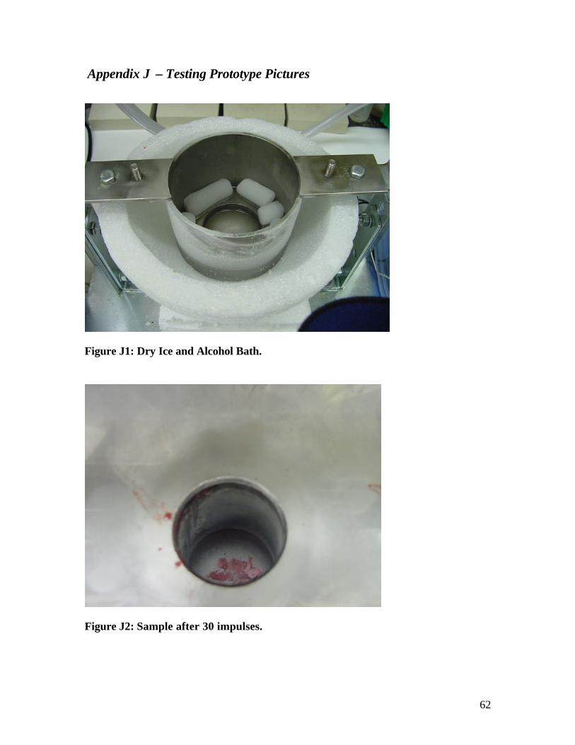
62
Appendix J – Testing Prototype Pictures
Figure J1: Dry Ice and Alcohol Bath.
Figure J2: Sample after 30 impulses.

63
Figure J3: Cooling Grinding Head in Dry Ice.
Figure J4: Grinding Tissue Sample. Lab PSI was only 30 psi as indicated by the regulator.

64
Appendix K - Procedure for Use
The following includes a step-by-step procedure for using the Cryopneumatic
Tissue Pulverizer.
Setup:
1. Affirm metal grinding chamber and head have been autoclaved
2. Immerse grinding head in liquid nitrogen*
3. Remove grinding chamber
4. Add dry ice and alcohol bath, stacking dry ice pellets around edge
5. Place grinding chamber in cooling chamber and tighten wing-nuts to secure
grinding chamber
6. Pour approximately 5 mL liquid nitrogen in grinding chamber
7. Insert tissue sample
8. Allow sample to cool (approximately 30 seconds)
9. Align grinding head over grinding chamber entrance
10. Plug in both electrical cords
11. Attach air hose to air supply securely with ring clamp
12. Turn switch ON
13. Allow pulverization for approximately 1 minute
14. Turn switch OFF
15. Remove wing-nuts to remove grinding chamber and empty sample into vial.
16. Autoclave grinding components for next use
*Step 2 will vary depending on whether a circuit by-pass is added to allow the
grinding head to be submerged in the liquid nitrogen while still attached.
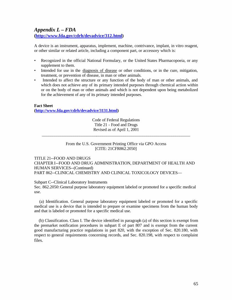
65
Appendix L – FDA (http://www.fda.gov/cdrh/devadvice/312.html) A device is an instrument, apparatus, implement, machine, contrivance, implant, in vitro reagent, or other similar or related article, including a component part, or accessory which is: • Recognized in the official National Formulary, or the United States Pharmacopoeia, or any
supplement to them. • Intended for use in the diagnosis of disease or other conditions, or in the cure, mitigation,
treatment, or prevention of disease, in man or other animals. • Intended to affect the structure or any function of the body of man or other animals, and
which does not achieve any of its primary intended purposes through chemical action within or on the body of man or other animals and which is not dependent upon being metabolized for the achievement of any of its primary intended purposes.
Fact Sheet (http://www.fda.gov/cdrh/devadvice/3131.html)
Code of Federal Regulations Title 21 - Food and Drugs
Revised as of April 1, 2001 _______________________________________________________________________
From the U.S. Government Printing Office via GPO Access
[CITE: 21CFR862.2050] TITLE 21--FOOD AND DRUGS CHAPTER I--FOOD AND DRUG ADMINISTRATION, DEPARTMENT OF HEALTH AND HUMAN SERVICES--(Continued) PART 862--CLINICAL CHEMISTRY AND CLINICAL TOXICOLOGY DEVICES— Subpart C--Clinical Laboratory Instruments Sec. 862.2050: General purpose laboratory equipment labeled or promoted for a specific medical use. (a) Identification. General purpose laboratory equipment labeled or promoted for a specific medical use is a device that is intended to prepare or examine specimens from the human body and that is labeled or promoted for a specific medical use. (b) Classification. Class I. The device identified in paragraph (a) of this section is exempt from the premarket notification procedures in subpart E of part 807 and is exempt from the current good manufacturing practice regulations in part 820, with the exception of Sec. 820.180, with respect to general requirements concerning records, and Sec. 820.198, with respect to complaint files.