Design, Modeling, and Analysis of a Novel Hydraulic Energy...
13
Research Article Design, Modeling, and Analysis of a Novel Hydraulic Energy-Regenerative Shock Absorber for Vehicle Suspension Junyi Zou, 1,2,3 Xuexun Guo, 1,2,3 Lin Xu, 1,2,3 Gangfeng Tan, 1,2,3 Chengcai Zhang, 1,2,3 and Jie Zhang 4 1 School of Automotive Engineering, Wuhan University of Technology, Wuhan 430070, China 2 Hubei Key Laboratory of Advanced Technology of Automotive Components, Wuhan University of Technology, Wuhan 430070, China 3 Hubei Collaborative Innovation Center for Automotive Components Technology, Wuhan University of Technology, Wuhan 430070, China 4 Technology Center, Wanxiang Group Corporation, Hangzhou 311215, China Correspondence should be addressed to Lin Xu; [email protected] Received 13 February 2017; Revised 31 May 2017; Accepted 21 June 2017; Published 8 August 2017 Academic Editor: Carlo Trigona Copyright © 2017 Junyi Zou et al. is is an open access article distributed under the Creative Commons Attribution License, which permits unrestricted use, distribution, and reproduction in any medium, provided the original work is properly cited. To reduce energy consumption or improve energy efficiency, the regenerative devices recently have drawn the public’s eyes. In this paper, a novel hydraulic energy-regenerative shock absorber (HERSA) is developed for vehicle suspension to regenerate the vibration energy which is dissipated by conventional viscous dampers into heat waste. At first, the schematic of HERSA is presented and a mathematic model is developed to describe the characteristic of HERSA. en the parametric sensitivity analysis of the vibration energy is expounded, and the ranking of their influences is 1 ≫ 2 > 1 > 2 ≈ . Besides, a parametric study of HERSA is adopted to research the influences of the key parameters on the characteristic of HERSA. Moreover, an optimization of HERSA is carried out to regenerate more power as far as possible without devitalizing the damping characteristic. To make the optimization results more close to the actual condition, the displacement data of the shock absorber in the road test is selected as the excitation in the optimization. e results show that the RMS of regenerated energy is up to 107.94 W under the actual excitation. Moreover it indicates that the HERSA can improve its performance through the damping control. 1. Introduction With the energy consumption rising rapidly, the energy crisis is being more and more urgent. e proportion of transportation energy consumption increases year by year, and the percent of which will come up to 26%. In gen- eral, the transportation of people and goods accounts for about 25% of total world energy consumption. Passenger transportation, in particular, light-duty vehicles, accounts for most transportation energy consumption, with light- duty vehicles consuming more energy than all modes of freight transportation, including heavy trucks, marine, and rail combined [1]. So a great number of countries have initiated the development of renewable power. Among this, the vibration energy of vehicle is one of the sources that can be harvested. In Figure 1 [2], the vehicle energy flows of a 2.5 L 2005 Camry are demonstrated. And Figure 1 shows that most fuel energy is wasted. erefore the energy regeneration can be considered as a new technology of energy saving, such as regenerative braking and regenerative suspension. As to energy harvesting, it can be traced back to many years ago. Okada and Harada [3] demonstrated an electrody- namic regenerative damper, and the power was harvested by a linear motor in the system. Suda and Shiiba [4] designed a multiple suspension which could realize the active control and energy regeneration. e active control strategy of energy-regenerative shock absorber was improved. Roshani et al. [5] conducted an experimental program to evaluate the potential of harvesting energy from roadways using piezoelectric materials, and it showed that the quantity and arrangement of the piezoelectric sensors alter the applied stresses, which leaded to variations in the generated output power. Zuo et al. [6] developed an electromagnetic energy Hindawi Shock and Vibration Volume 2017, Article ID 3186584, 12 pages https://doi.org/10.1155/2017/3186584
Transcript of Design, Modeling, and Analysis of a Novel Hydraulic Energy...
Research ArticleDesign, Modeling, and Analysis of a Novel HydraulicEnergy-Regenerative Shock Absorber for Vehicle Suspension
Junyi Zou,1,2,3 Xuexun Guo,1,2,3 Lin Xu,1,2,3 Gangfeng Tan,1,2,3
Chengcai Zhang,1,2,3 and Jie Zhang4
1School of Automotive Engineering, Wuhan University of Technology, Wuhan 430070, China2Hubei Key Laboratory of Advanced Technology of Automotive Components, Wuhan University of Technology, Wuhan 430070, China3Hubei Collaborative Innovation Center for Automotive Components Technology,Wuhan University of Technology, Wuhan 430070, China4Technology Center, Wanxiang Group Corporation, Hangzhou 311215, China
Correspondence should be addressed to Lin Xu; [email protected]
Received 13 February 2017; Revised 31 May 2017; Accepted 21 June 2017; Published 8 August 2017
Academic Editor: Carlo Trigona
Copyright © 2017 Junyi Zou et al.This is an open access article distributed under theCreativeCommonsAttribution License, whichpermits unrestricted use, distribution, and reproduction in any medium, provided the original work is properly cited.
To reduce energy consumption or improve energy efficiency, the regenerative devices recently have drawn the public’s eyes. Inthis paper, a novel hydraulic energy-regenerative shock absorber (HERSA) is developed for vehicle suspension to regenerate thevibration energy which is dissipated by conventional viscous dampers into heat waste. At first, the schematic of HERSA is presentedand a mathematic model is developed to describe the characteristic of HERSA. Then the parametric sensitivity analysis of thevibration energy is expounded, and the ranking of their influences is 𝑘1 ≫ 𝑚2 > 𝑚1 > 𝑘2 ≈ 𝑐𝑠. Besides, a parametric study ofHERSA is adopted to research the influences of the key parameters on the characteristic of HERSA. Moreover, an optimizationof HERSA is carried out to regenerate more power as far as possible without devitalizing the damping characteristic. To make theoptimization results more close to the actual condition, the displacement data of the shock absorber in the road test is selected as theexcitation in the optimization. The results show that the RMS of regenerated energy is up to 107.94 W under the actual excitation.Moreover it indicates that the HERSA can improve its performance through the damping control.
1. Introduction
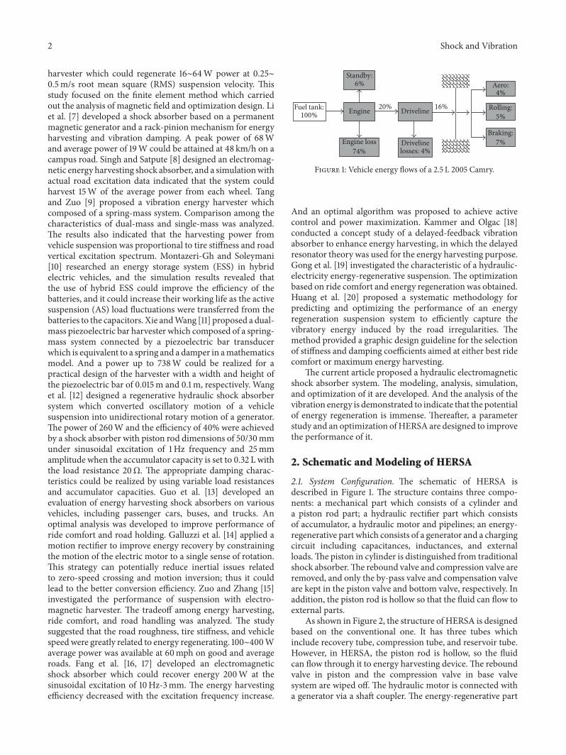
With the energy consumption rising rapidly, the energycrisis is being more and more urgent. The proportion oftransportation energy consumption increases year by year,and the percent of which will come up to 26%. In gen-eral, the transportation of people and goods accounts forabout 25% of total world energy consumption. Passengertransportation, in particular, light-duty vehicles, accountsfor most transportation energy consumption, with light-duty vehicles consuming more energy than all modes offreight transportation, including heavy trucks, marine, andrail combined [1]. So a great number of countries haveinitiated the development of renewable power. Among this,the vibration energy of vehicle is one of the sources that canbe harvested. In Figure 1 [2], the vehicle energy flows of a 2.5 L2005 Camry are demonstrated. And Figure 1 shows that most
fuel energy is wasted. Therefore the energy regeneration canbe considered as a new technology of energy saving, such asregenerative braking and regenerative suspension.
As to energy harvesting, it can be traced back to manyyears ago. Okada and Harada [3] demonstrated an electrody-namic regenerative damper, and the power was harvested bya linear motor in the system. Suda and Shiiba [4] designeda multiple suspension which could realize the active controland energy regeneration. The active control strategy ofenergy-regenerative shock absorber was improved. Roshaniet al. [5] conducted an experimental program to evaluatethe potential of harvesting energy from roadways usingpiezoelectric materials, and it showed that the quantity andarrangement of the piezoelectric sensors alter the appliedstresses, which leaded to variations in the generated outputpower. Zuo et al. [6] developed an electromagnetic energy
HindawiShock and VibrationVolume 2017, Article ID 3186584, 12 pageshttps://doi.org/10.1155/2017/3186584
2 Shock and Vibration
harvester which could regenerate 16∼64W power at 0.25∼0.5m/s root mean square (RMS) suspension velocity. Thisstudy focused on the finite element method which carriedout the analysis of magnetic field and optimization design. Liet al. [7] developed a shock absorber based on a permanentmagnetic generator and a rack-pinion mechanism for energyharvesting and vibration damping. A peak power of 68Wand average power of 19W could be attained at 48 km/h on acampus road. Singh and Satpute [8] designed an electromag-netic energy harvesting shock absorber, and a simulationwithactual road excitation data indicated that the system couldharvest 15W of the average power from each wheel. Tangand Zuo [9] proposed a vibration energy harvester whichcomposed of a spring-mass system. Comparison among thecharacteristics of dual-mass and single-mass was analyzed.The results also indicated that the harvesting power fromvehicle suspension was proportional to tire stiffness and roadvertical excitation spectrum. Montazeri-Gh and Soleymani[10] researched an energy storage system (ESS) in hybridelectric vehicles, and the simulation results revealed thatthe use of hybrid ESS could improve the efficiency of thebatteries, and it could increase their working life as the activesuspension (AS) load fluctuations were transferred from thebatteries to the capacitors. Xie andWang [11] proposed a dual-mass piezoelectric bar harvester which composed of a spring-mass system connected by a piezoelectric bar transducerwhich is equivalent to a spring and a damper in amathematicsmodel. And a power up to 738W could be realized for apractical design of the harvester with a width and height ofthe piezoelectric bar of 0.015m and 0.1m, respectively. Wanget al. [12] designed a regenerative hydraulic shock absorbersystem which converted oscillatory motion of a vehiclesuspension into unidirectional rotary motion of a generator.The power of 260W and the efficiency of 40% were achievedby a shock absorber with piston rod dimensions of 50/30mmunder sinusoidal excitation of 1Hz frequency and 25mmamplitude when the accumulator capacity is set to 0.32 L withthe load resistance 20Ω. The appropriate damping charac-teristics could be realized by using variable load resistancesand accumulator capacities. Guo et al. [13] developed anevaluation of energy harvesting shock absorbers on variousvehicles, including passenger cars, buses, and trucks. Anoptimal analysis was developed to improve performance ofride comfort and road holding. Galluzzi et al. [14] applied amotion rectifier to improve energy recovery by constrainingthe motion of the electric motor to a single sense of rotation.This strategy can potentially reduce inertial issues relatedto zero-speed crossing and motion inversion; thus it couldlead to the better conversion efficiency. Zuo and Zhang [15]investigated the performance of suspension with electro-magnetic harvester. The tradeoff among energy harvesting,ride comfort, and road handling was analyzed. The studysuggested that the road roughness, tire stiffness, and vehiclespeedwere greatly related to energy regenerating. 100∼400Waverage power was available at 60mph on good and averageroads. Fang et al. [16, 17] developed an electromagneticshock absorber which could recover energy 200W at thesinusoidal excitation of 10Hz-3mm. The energy harvestingefficiency decreased with the excitation frequency increase.
Fuel tank:100%
Standby:6%
Engine
Engine loss74%
Driveline
Drivelinelosses: 4%
16%20%
Aero:4%
Rolling:5%
Braking:7%
Figure 1: Vehicle energy flows of a 2.5 L 2005 Camry.
And an optimal algorithm was proposed to achieve activecontrol and power maximization. Kammer and Olgac [18]conducted a concept study of a delayed-feedback vibrationabsorber to enhance energy harvesting, in which the delayedresonator theory was used for the energy harvesting purpose.Gong et al. [19] investigated the characteristic of a hydraulic-electricity energy-regenerative suspension. The optimizationbased on ride comfort and energy regeneration was obtained.Huang et al. [20] proposed a systematic methodology forpredicting and optimizing the performance of an energyregeneration suspension system to efficiently capture thevibratory energy induced by the road irregularities. Themethod provided a graphic design guideline for the selectionof stiffness and damping coefficients aimed at either best ridecomfort or maximum energy harvesting.
The current article proposed a hydraulic electromagneticshock absorber system. The modeling, analysis, simulation,and optimization of it are developed. And the analysis of thevibration energy is demonstrated to indicate that the potentialof energy regeneration is immense. Thereafter, a parameterstudy and an optimization ofHERSA are designed to improvethe performance of it.
2. Schematic and Modeling of HERSA
2.1. System Configuration. The schematic of HERSA isdescribed in Figure 1. The structure contains three compo-nents: a mechanical part which consists of a cylinder anda piston rod part; a hydraulic rectifier part which consistsof accumulator, a hydraulic motor and pipelines; an energy-regenerative part which consists of a generator and a chargingcircuit including capacitances, inductances, and externalloads.The piston in cylinder is distinguished from traditionalshock absorber.The rebound valve and compression valve areremoved, and only the by-pass valve and compensation valveare kept in the piston valve and bottom valve, respectively. Inaddition, the piston rod is hollow so that the fluid can flow toexternal parts.
As shown in Figure 2, the structure of HERSA is designedbased on the conventional one. It has three tubes whichinclude recovery tube, compression tube, and reservoir tube.However, in HERSA, the piston rod is hollow, so the fluidcan flow through it to energy harvesting device.The reboundvalve in piston and the compression valve in base valvesystem are wiped off. The hydraulic motor is connected witha generator via a shaft coupler. The energy-regenerative part

Shock and Vibration 3
Compression strokeExtension stroke
Reservoir tube
piston
Seal & Guide assy
By-pass valve
Gas
Base valve assy
Replenishing valve
Motor
DC generator
External load
Inductance
Piston rod
2
1
(a)
M E
Electricgenerator
Hydraulicmotor
Compressioncavity
Recoverycavity
Energyregeneration systemCheck
valve 2
Checkvalve 1
Accumulator
(b)
Figure 2: Schematic of HERSA. (a) The assembly diagram of HERSA. (b) The equivalent diagram of HERSA.
has a common rotating mechanism which can be founded insome references.
When in the extension stroke, the fluid flows fromrebound chamber to hollow piston rod, then flows throughthe hollow channel in piston rod, along the pipeline to thehydraulic pump, flows through the hydraulic motor to thereservoir tube, and passes the replenishing valve back to thecompression chamber at last. In this stroke, most energy canbe harvested, and the external load can be adjusted to achievesemiactive suspension.
When in the compression stroke, the process is a littlemore complicated and the flow process can be divided intotwo parts:
(1) At first, because of the small cracking pressure, mostof the fluid flows through the by-pass valve fromcompression chamber to replenishing chamber;
(2) After step (1), the upper chamber will be filled withoil.There is a volumetric difference between the upperand lower chamber because of the existence of pistonrod. Just because of the volumedifference, the residualoil in lower chamber will flow through the hollowpiston to the regenerative part. As the volume ofpiston rod is small, so the volume of oil which flowsinto hydraulic motor is small too, and finally theharvested energy is little.
2.2. Mathematic Model of HERSA. Based on the workingprinciple of HERSA shown in the Figure 2, a mathematicmodel is proposed to demonstrate the system dynamics, such
as the damping characteristic. In the system, the hydraulicflow and generator circuit are important to the characteristic.
In the shock absorber, the damping force can be definedbelow:
𝐹𝑐 = 𝑃𝑓𝑆𝑓 − 𝑃𝑦𝑆𝑦, (1)
where 𝑃𝑓 and 𝑃𝑦 are, respectively, pressure of upper andinferior chamber and 𝑆𝑓 and 𝑆𝑦 are the ring area and surfacearea of piston.
While taking into account internal leakage in the system,it is understood that the fluid should flow through the checkvalve, the pipeline, and the hydraulicmotor-generator circuit.The damping force is dependent on the three parts above.To describe the damping characteristic in detail, the twoaspects, the hydraulic and the circuit system, are described,respectively.
2.2.1. Modeling of the Hydraulic System. In the extensionstroke, the fluid firstly flows through the elbow in the hollowpiston rod.This elbow can lead to the pressure partial loss, sothe pressure drop can be presented by
Δ𝑃𝑗𝑐 = 𝜀𝜌V𝑗𝑐2 , (2)
where Δ𝑃𝑗𝑐 is the pressure drop of elbows in the hydraulicsystem; 𝜀 is the local resistance coefficient; 𝜌 is the density ofhydraulic oil; V𝑗𝑐 is the flow velocity of the oil in this area.
Then the fluid flows through the hollow piston rod; thehollow channel can be simplified as a pipeline of short length.
4 Shock and Vibration
Assuming the fluid is in laminar flow state, so the pressuredrop can be presented by
Δ𝑃𝑙 = 𝜆𝜌𝑙𝑙V2𝑙2 . (3)
In the rubber hose, there are the common equations
𝜆 = 80𝑅𝑒 (4)
𝑅𝑒 = 2𝑟𝑙V𝑙𝑢V . (5)
Combining (4) with (5), (3) can be presented by
Δ𝑃𝑙 = 10𝑢V𝜌𝑙𝑙V𝑙𝑟𝑙2 , (6)
where Δ𝑃𝑙 is the pressure drop in pipeline; 𝜆 is the coefficientof tube friction; 𝑙𝑙 is the length of pipeline; V𝑙 is the flowvelocity of oil; 𝑟𝑙 is the radius of pipeline; 𝑅𝑒 is the Reynoldsnumber; 𝑢V is the kinematic viscosity of oil.
The valves in piston valve or base valve can lead to flowpressure drop; the check valves above are regarded as thin-wall holes, so the pressure drop can be presented by
𝑄𝑖 = 𝐶𝑑𝑆𝑖√2Δ𝑃𝑖𝜌 (7)
Δ𝑃𝑖 = 𝑄𝑖2𝜌2𝐶𝑑𝑆𝑖2 , (8)
where Δ𝑃𝑖 is the pressure drop of the check valve 𝑖; 𝑄𝑖 is theflow rate of the check valve 𝑖; 𝐶𝑑 is the flow coefficient; 𝑆𝑖 isthe cross area of the check valve 𝑖.
The reservoir tube in Figure 1 can be treated as anaccumulator in the system; the gas is assumed to be ideal gas.According to Boyle’s law, the gas pressure can be presented by
𝑃0𝑉0𝑛 = 𝑃𝑔𝑉𝑔𝑛𝑃𝑔 = 𝑃0 [ 𝑉0𝑉0 − (𝑆𝑦 − 𝑆𝑓) ∫ V (𝑡) 𝑑𝑡]
𝑛
, (9)
where 𝑃0 is the initial charge pressure of gas in reservoir tube;𝑉0 is the initial charge volume;𝑃𝑔 and𝑉𝑔 are, respectively, thegas pressure and volume after the fluid flows into reservoirtube; 𝑛 is the gas polytropic index; V(𝑡) is the velocity of piston.2.2.2. Modeling of the Hydraulic System. The electric circuitconsists of a motor, a DC generator, and an energy recoverycircuit, where the circuit includes the inductances and theexternal resistances.
In the extension stroke, the high pressure oil drives thehydraulic motor; then the motor drives the generator by acoupler. According to their connection, the rotational speedand the output torque of hydraulic motor can be presented by
𝑛hm = 𝑄hm𝑞 𝜂V𝑇hm = Δ𝑃𝑚𝑞2𝜋 𝜂𝑚,
(10)
where 𝑛hm and 𝑇hm are, respectively, the rotational speedand output torque of the hydraulic motor; 𝑞 is the motordisplacement; 𝑄hm is the flow rate through the hydraulicmotor; Δ𝑃𝑚 is the pressure drop between the inlet and outletof hydraulicmotor; 𝜂V and 𝜂𝑚 are, respectively, the volumetricefficiency and mechanical efficiency of the hydraulic motor.
The hydraulic motor drives the generator. According tothemoment equilibrium principle and the law of electromag-netic induction, the electromotive force (EMF) voltage, theelectromagnetic torque, and the input torque of generator canbe presented by
𝑇𝐺𝑖 = 𝐽𝑚�̇� + 𝑇𝑒𝑇𝑒 = 𝑘𝑡𝐼𝑈𝑒 = 𝑘V𝜔 = 𝐼𝑅,
(11)
where 𝑇𝐺𝑖 is the input torque of generator; 𝐽𝑚 is the totalrotational inertia of motor-generator unit; 𝜔 is the rotationalspeed of generator; 𝑇𝑒 is the electromagnetic torque ofgenerator in power regenerated status; 𝑘𝑡 and 𝑘V are the torqueconstant and EMF constant of generator, respectively; 𝑈𝑒 isthe EMF voltage; 𝐼 is the electric current in the circuit; 𝑅 isthe resistance in the circuit.
Ignoring the rotational inertia of the rotor in generator[21], the pressure drop of hydraulic motor can be presentedby
Δ𝑃𝑚 = 4𝜋2𝑄hm𝑘𝑡𝑘V𝜂V𝑞2𝑅𝜂𝑚 . (12)
As to the compression stroke, the volumetric differencecan lead to fluids flow through the hydraulic motor, so thepressure drop can be presented by
Δ𝑃V𝑚 = 4𝜋2𝑄V𝑚𝑘𝑡𝑘V𝜂V𝑞2𝑅𝜂𝑚 (13)
𝑄V𝑚 = 𝑆V |V| = 𝜋𝑟V2 |V| , (14)
where Δ𝑃V𝑚 is the pressure drop of the hydraulic motorin compression stroke; 𝑄V𝑚 is the flow rate through thehydraulic motor; 𝑆V is the cross area of the hollow piston rodwall; 𝑟V is the equivalent radius of the cross area.
Ignoring the internal leakage in hydraulic cylinder, theflow rate in all parts of the hydraulic system is the same, soit can be presented by
𝑄𝑐 = 𝑆𝑓 |V| = 𝑆𝑖V𝑖 = 𝜋𝑟𝑙2V𝑙 = 𝜋𝑟𝑙2V𝑗𝑐. (15)
According to the pressure equation, the pressure in thesystem can be presented by
𝑃𝑓 = 𝑃𝑦 + Δ𝑃𝑗𝑐 + Δ𝑃𝑙 + Δ𝑃𝑖 + Δ𝑃𝑚. (16)
Shock and Vibration 5
(a) (b)
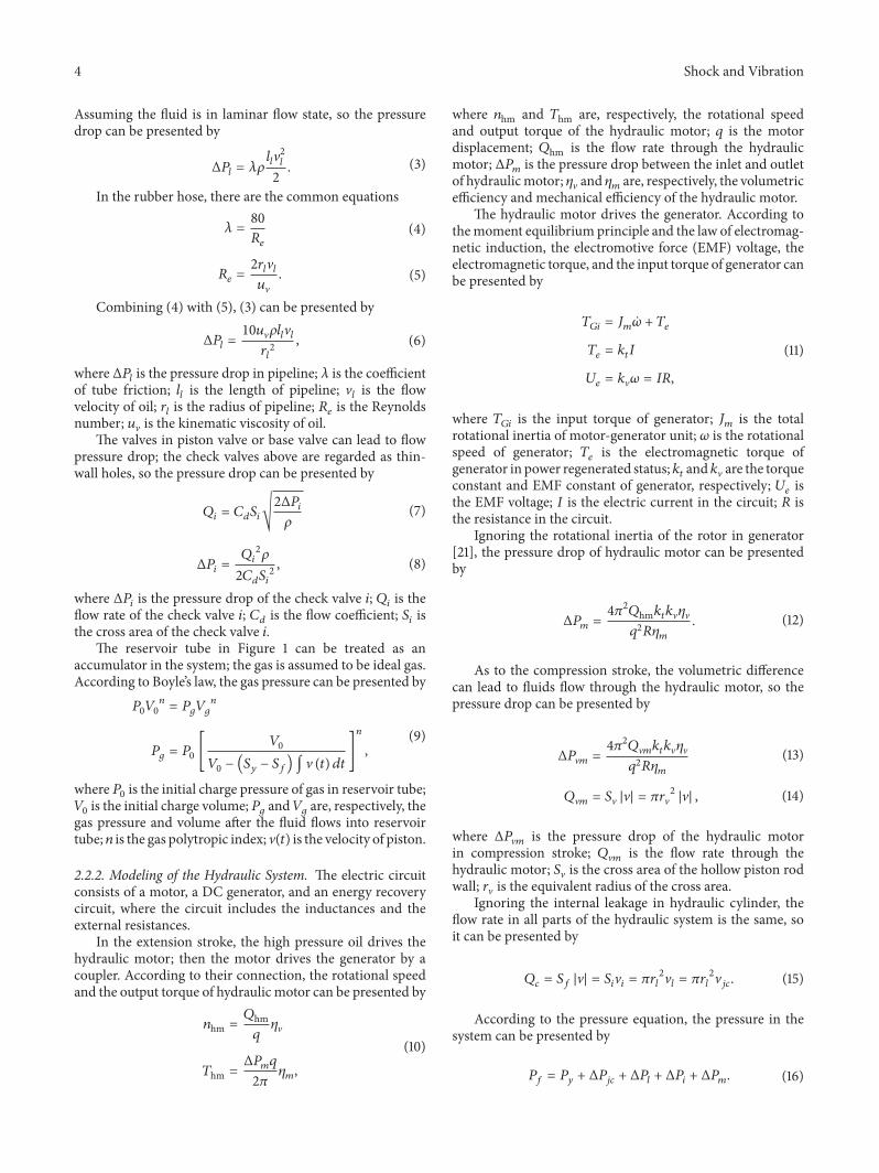
Figure 3: The prototype of the cylinder. (a) The drawing of thecylinder. (b) The fabrication of the cylinder.
Therefore, based on the above inference, the dampingforce can be presented by
𝐹𝑐𝑦 = 𝑃𝑔 (𝑆𝑦 − 𝑆𝑓) + 𝜌𝑆𝑦3V (𝑡)22𝐶𝑑𝑆22 + 4𝜋2𝑄V𝑚𝑘𝑡𝑘V𝑞2𝑅𝜂𝑚+ 10𝑢V𝜌𝑙𝑙𝑆𝑦2𝜋𝑟𝑙4 V (𝑡) + 𝜀𝜌𝑆𝑦32𝜋2𝑟𝑙4 V (𝑡)
2
𝐹𝑐𝑒 = 𝑃𝑔 (𝑆𝑓 − 𝑆𝑦) + 𝜌𝑆𝑦3V (𝑡)22𝐶𝑑𝑆12 + 4𝜋2𝑄hm𝑘𝑡𝑘V𝑞2𝑅𝜂𝑚+ 10𝑢V𝜌𝑙𝑙𝑆𝑦𝑆𝑓𝜋𝑟𝑙4 V (𝑡) + ∑ 𝜀𝜌𝑆𝑦𝑆𝑓22𝜋𝑟𝑙4 V (𝑡)2 .
(17)
In the equation, 𝐹𝑐𝑦 and 𝐹𝑐𝑒 are the damping force incompression stroke and extension stroke, respectively.
2.3. Prototype of the Cylinder in HERSA. As shown inFigure 3, the prototype of the cylinder inHERSA is fabricatedon the basis of a traditional shock absorber according tothe conceptual design in Figure 2. In consideration of theworse road excitation of SUVs or heavy trucks, this designtarget is commercial vehicle. The primary components in thesystem are a hydraulic cylinder, a motor, oil tubes, and a DCgenerator.
3. Analysis of Suspension Vibration Energy
3.1. Suspension Vibration Energy. The road roughness canlead to the vibration of the vehicle suspension. The vibrationenergy is transformed into thermal energy by the traditional
k1
k2 cs
z2
z1
q
m1
m2
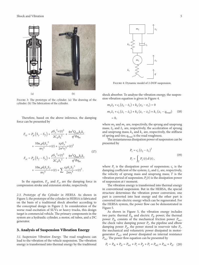
Figure 4: Dynamic model of 2-DOF suspension.
shock absorber. To analyze the vibration energy, the suspen-sion vibration equation is given in Figure 4.
𝑚2�̈�2 + 𝑐𝑠 (�̇�2 − �̇�1) + 𝑘2 (𝑧2 − 𝑧1) = 0𝑚1�̈�1 + 𝑐𝑠 (�̇�1 − �̇�2) + 𝑘2 (𝑧1 − 𝑧2) + 𝑘1 (𝑧1 − 𝑞road)
= 0,(18)
where𝑚2 and𝑚1 are, respectively, the sprung and unsprungmass; �̈�2 and �̈�1 are, respectively, the acceleration of sprungand unsprung mass; 𝑘2 and 𝑘1 are, respectively, the stiffnessof spring and tire; 𝑞road is the road roughness.
The instantaneous dissipation power of suspension can bepresented by
𝑃𝑠 = 𝑐𝑠 (�̇�2 − �̇�1)2𝑃𝑡 = ∫
𝑇𝑃𝑠 (𝑡) 𝑑 (𝑡) , (19)
where 𝑃𝑠 is the dissipation power of suspension; 𝑐𝑠 is thedamping coefficient of the system; �̇�2 and �̇�1 are, respectively,the velocity of sprung mass and unsprung mass; 𝑇 is thevibration period of suspension; 𝑃𝑠(𝑡) is the dissipation powerof suspension at 𝑡moment.
The vibration energy is transformed into thermal energyin conventional suspension. But in the HERSA, the specialstructure determines the vibration power conversion; onepart is converted into heat energy and the other part isconverted into electric energy which can be regenerated. Forthe HERSA system, the power flow can be demonstrated inFigure 5.
As shown in Figure 5, the vibration energy includestwo parts: thermal 𝑃th and electric 𝑃el power; the thermalpower 𝑃th consists of the mechanical friction power 𝑃𝑚1,the check valve damping power 𝑃𝑐, the pipeline and elbowdamping power 𝑃𝑝, the power stored in reservoir tube 𝑃𝑟,the mechanical and volumetric power dissipated in motor-generator 𝑃𝑚2, and power dissipated on internal resistance𝑃rin. The power flow equation can be presented by
𝑃𝑡 = 𝑃th + 𝑃el = 𝑃𝑚1 + 𝑃𝑐 + 𝑃𝑝 + 𝑃𝑟 + 𝑃𝑚2 + 𝑃rin + 𝑃el. (20)

6 Shock and Vibration
Mechanicalloss powerPm1 Power in the
flow valve andcompensation
valve Pc
Power in thehydraulic pipeand elbow Pp
Hydraulicdissipationpower in shockabsorber Pℎ
Power stored inthe reservoirtube Pr
Mechanical andvoluminal losspower Pm2
Power inputtedinto electricgenerator Pgin
Power inputtedinto the hydraulicmotor Pmin
Power dissipatedin internalresistance Prin
Power outputtedto external load
Pel
Thermalpower Pth
Suspensionvibrationenergy Pt
Figure 5: Power flow chart of suspension vibration energy.
0.0
0.3
0.6
0.9
1.2
1.5
1.8
Nor
mal
izat
ion
of R
MS
pow
er
N
Parameter variation1.45N1.3N1.15N0.85N0.60N0.45N
k1
k2
csm1
m2
(a)
0
20
40
60
80
100
120RM
S po
wer
(W)
B C DARoad grade
(b)
Figure 6: Parameter analysis of suspension vibration energy. (a) The influence of the parameters on RMS dissipation power, on the B graderoad. (b) The influence of different roads on RMS dissipation power.
3.2. Sensitivity Analysis of Suspension Vibration Energy. Thevibration energy is related to suspension system and theroad, so the parameter study is carried out to analyze thesensitivity. Amodel of quarter vehicle is established to analyzethe influences of vehicle parameters on vibration energy. Thevalues of the parameters are demonstrated in Table 1.
Based on the parameters in the Table 1, a simulationmodel is carried out to evaluate the influences of the vehicleparameters and different grade roads on suspension vibrationenergy.
In Figure 6(a), one parameter changes while the othersare kept at nominal value. The 𝑁 represents the nominalvalue of the parameters, and the parameters change in same
Table 1: Parameters of the quarter vehicle model.
Parameter of vehicle ValveSprung mass/𝑚2 350/kgUnsprung mass/𝑚1 40/kgSpring stiffness/𝑘2 20000/(N⋅m−1)Tire stiffness/𝑘1 180000/(N⋅m−1)Damping rate/𝑐𝑠 1500/(N⋅s⋅m−1)
proportion of 0.15𝑁. The influences of the parameters onvibration energy are as follows:

Shock and Vibration 7
−12000
−8000
−4000
0
4000
8000
Dam
ping
forc
e (N
)
0.01 0.03 0.05−0.03 −0.01−0.05
Displacement (m)
0.2 bar1.0 bar
1.8 bar2.6 bar
(a)
0
−15000
−12000
−9000
−6000
−3000
3000
6000
Dam
ping
forc
e (N
)
−0.03 −0.01−0.05 0.03 0.050.01Displacement (m)
0.2 bar1.0 bar
1.8 bar2.6 bar
(b)
Figure 7: The influence of check valve in HERSA. (a) The influence of by-pass valve on damping characteristics. (b) The influence ofreplenishing valve on damping characteristics.
(1) TheRMSpower is proportional to 𝑘1,𝑚2, and𝑚1, andthe increasing rate ranking is 𝑘1 ≫ 𝑚2 > 𝑚1;
(2) The 𝑘2 and 𝑐𝑠 almost have no influences on vibrationenergy, and the RMS power decreases at first andgradually tends to a constant value as 𝑐𝑠 increases;
(3) In Figure 6(b), the road grade is according to the ISOstandard [21].TheRMS power increases with the roadgrade increases from A to D, and the increasing rategets bigger and bigger from A to D. The results arecoincident with the results in Galluzzi et al. [14].
4. Parametric Analysis of HERSA
In the HERSA, there are many components in the system,such as the hydraulic cylinder, the piston, the pipeline, thecheck valve, the reservoir tube, the motor, the generator, andthe electric elements. The parameter is enormous. The initialparameter valve of HERSA is shown in Table 2.
In this paper, the parameters are various and shown inTable 2; the effects of them on the damping characteristicsof HERSA and regenerated energy are demonstrated in thefollowing analysis. A sinusoidal excitation is set as the roadroughness, and it can be presented by
𝑞road = 𝐴 sin (2𝜋𝑓𝑡) . (21)
𝐴 and 𝑓 are, respectively, the amplitude and frequency ofthe sinusoidal excitation, and the initial valves of𝐴 and 𝑓 are50mm and 1.67Hz respectively.
4.1. Parameter Study
4.1.1. Check Valve. In the system, there are by-pass valve andreplenishing valve. The by-pass valve mainly works in thecompression stroke, and the replenishing valve mainly worksin the extension stroke. And the key parameter of valves is the
Table 2: Parameters of the HERSA.
Parameter Valve𝐷 65mm𝑑 26mm𝜌 850 (kg/m3)𝑃0 15 bar𝑉0 0.5 L𝑞 10 (mL/r)𝜂V 0.9𝑛 1.2𝐽𝑚 10−7 (kg⋅m2)𝑃crack-valve1 0.2 bar𝑙𝑙 500mm𝑟𝑙 25mm𝑐𝑑 0.6𝑘𝑡 0.25 (N⋅m/A)𝑘V 0.25 (V⋅s/rad)𝜀 1.34𝜂𝑚 0.9𝑅𝑖𝑛 0.6Ω𝑅𝑜𝑢 15Ω𝑃crack-valve2 0.2 bar
cracking pressure. It affects greatly the damping force, and theinfluence diagram is presented in Figure 7.
As shown in Figure 7, the by-pass valve works in thecompression stroke, so, in Figure 7(a), the damping force inextension stroke almost has no changes, whereas the dampingforce in compression stroke increases with the increase ofcracking pressure. For the by-pass valve, the increase of Δ𝑃leads to the damping force increasing according to (8). Asto Figure 7(b), the damping force in the extension stroke
8 Shock and VibrationD
ampi
ng fo
rce (
N)
8 cc9 cc10 cc
11 cc12 cc
0
−17500
−14000
−10500
7000
−7000
3500
−3500
0.01 0.03 0.05−0.03 −0.01−0.05
Displacement (m)
(a)
8 cc9 cc10 cc
11 cc12 cc
0
1000
2000
3000
4000
5000
6000
Pow
er (W
)
1 2 3 40Time (S)
(b)
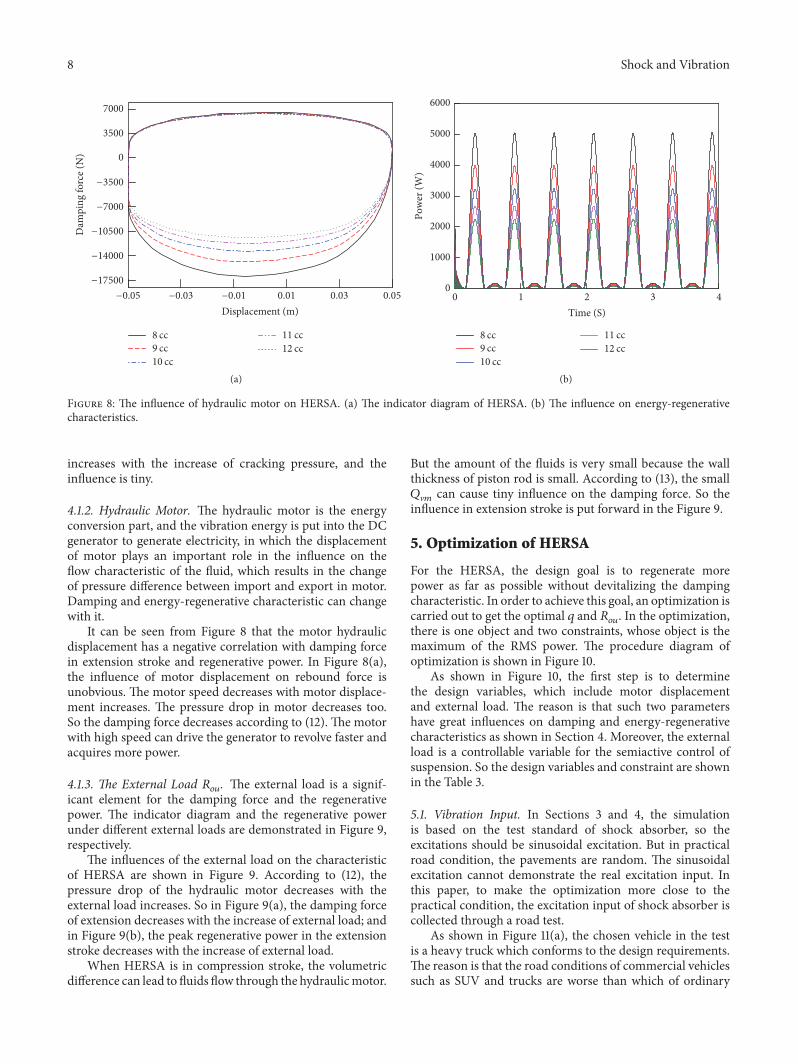
Figure 8: The influence of hydraulic motor on HERSA. (a) The indicator diagram of HERSA. (b) The influence on energy-regenerativecharacteristics.
increases with the increase of cracking pressure, and theinfluence is tiny.
4.1.2. Hydraulic Motor. The hydraulic motor is the energyconversion part, and the vibration energy is put into the DCgenerator to generate electricity, in which the displacementof motor plays an important role in the influence on theflow characteristic of the fluid, which results in the changeof pressure difference between import and export in motor.Damping and energy-regenerative characteristic can changewith it.
It can be seen from Figure 8 that the motor hydraulicdisplacement has a negative correlation with damping forcein extension stroke and regenerative power. In Figure 8(a),the influence of motor displacement on rebound force isunobvious. The motor speed decreases with motor displace-ment increases. The pressure drop in motor decreases too.So the damping force decreases according to (12). The motorwith high speed can drive the generator to revolve faster andacquires more power.
4.1.3. The External Load 𝑅𝑜𝑢. The external load is a signif-icant element for the damping force and the regenerativepower. The indicator diagram and the regenerative powerunder different external loads are demonstrated in Figure 9,respectively.
The influences of the external load on the characteristicof HERSA are shown in Figure 9. According to (12), thepressure drop of the hydraulic motor decreases with theexternal load increases. So in Figure 9(a), the damping forceof extension decreases with the increase of external load; andin Figure 9(b), the peak regenerative power in the extensionstroke decreases with the increase of external load.
When HERSA is in compression stroke, the volumetricdifference can lead to fluids flow through the hydraulicmotor.
But the amount of the fluids is very small because the wallthickness of piston rod is small. According to (13), the small𝑄V𝑚 can cause tiny influence on the damping force. So theinfluence in extension stroke is put forward in the Figure 9.
5. Optimization of HERSA
For the HERSA, the design goal is to regenerate morepower as far as possible without devitalizing the dampingcharacteristic. In order to achieve this goal, an optimization iscarried out to get the optimal 𝑞 and 𝑅𝑜𝑢. In the optimization,there is one object and two constraints, whose object is themaximum of the RMS power. The procedure diagram ofoptimization is shown in Figure 10.
As shown in Figure 10, the first step is to determinethe design variables, which include motor displacementand external load. The reason is that such two parametershave great influences on damping and energy-regenerativecharacteristics as shown in Section 4. Moreover, the externalload is a controllable variable for the semiactive control ofsuspension. So the design variables and constraint are shownin the Table 3.
5.1. Vibration Input. In Sections 3 and 4, the simulationis based on the test standard of shock absorber, so theexcitations should be sinusoidal excitation. But in practicalroad condition, the pavements are random. The sinusoidalexcitation cannot demonstrate the real excitation input. Inthis paper, to make the optimization more close to thepractical condition, the excitation input of shock absorber iscollected through a road test.
As shown in Figure 11(a), the chosen vehicle in the testis a heavy truck which conforms to the design requirements.The reason is that the road conditions of commercial vehiclessuch as SUV and trucks are worse than which of ordinary

Shock and Vibration 9
Table 3: Parameter determination of the optimization.
Parameter determination Range
Variable determination Hydraulic motor displacement/Dis 5∼40/(mL/r)External load/𝑅 5–40/Ω
Constraint condition 𝐹𝑐𝑒 8000∼12000/(N)𝐹𝑐𝑦 −6000∼−3000/(N)
10 Ohm15Ohm
20Ohm25 Ohm
−16000
−12000
−8000
−4000
0
4000
8000
Dam
ping
forc
e (N
)
0.01 0.03 0.05−0.03 −0.01−0.05
Displacement (m)
(a)
10 Ohm15Ohm
20Ohm25 Ohm
0
1000
2000
3000
4000
5000
Pow
er (W
)1 2 3 40
Time (S)
(b)
Figure 9: The influence of external load on HERSA. (a) The indicator diagram of HERSA. (b) The influence on energy-regenerativecharacteristics.
Optimized-objectRegenerative
energyHERSA
Parameter determination
Exci
tatio
n
Optimal value
Vibrationinput fromroad test
MIGA
Figure 10: The optimization procedure diagram.
passenger cars, and according to the relative analysis inSection 3, the commercial vehicles on worse road have biggerenergy-regenerative potential. So a light truck is selectedfor this test. Figures 11(c) and 11(d) are displacement sensorand data collection equipment, respectively. The suspensionworking states can be obtained through the test above.
To analyze the effects of different parameters on HERSA,several special road pavements are selected to compare theperformance of HERSA. And Figure 12 is physical image ofthese roads.
In the test, the sensor is fixed on the front suspension of atruckwith half loads at 50 km/h.Through the test, themotionstate of shock absorber can be obtained, and it is presented inFigure 13.
5.2. Optimization and Results. In the optimization, an algo-rithm named Multi-Island Genetic Algorithm (MIGA) wasadopted to perform the process. Considering that the con-straint condition should be prioritized, so weight factors of𝐹𝑐𝑒 and 𝐹𝑐𝑦 are 0.5 and 0.5, respectively. The block diagram isshown in Figure 14.
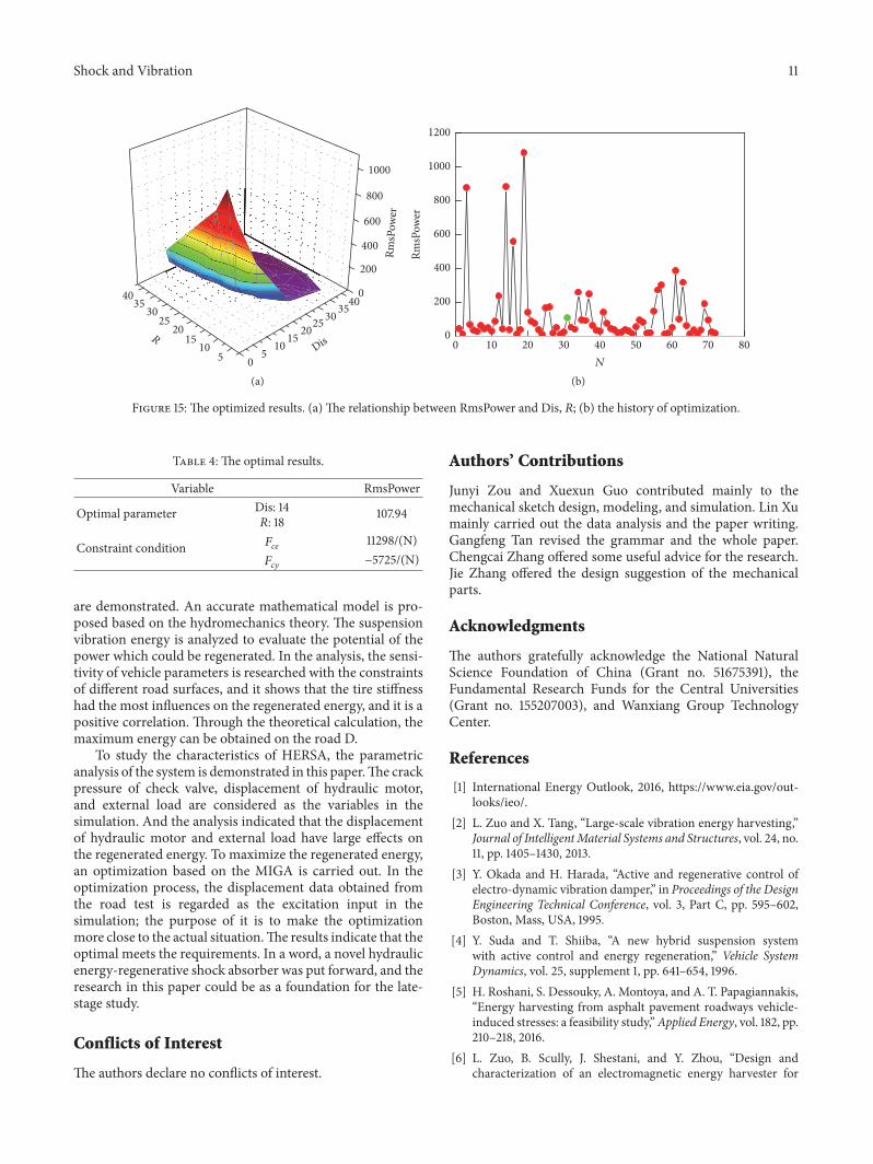
The optimization results are shown in Figure 15. InFigure 15, the relationship between RmsPower and Dis, 𝑅 ispresented. And Table 4 showed the RMS value of energy andthe corresponding damping force. After optimization, theregenerated energy increased greatly within the constraintcondition. In summary, through an overall consideration, theoptimization could improve the performance of HERSA, andit showed the semiactive control of HERSA was feasible.

10 Shock and Vibration
(a) (b)
(c) (d)Figure 11:The vehicle test for road roughness. (a)The vehicle in the test; (b) the location of sensor on the shock absorber; (c) the displacementsensor; (d) data collection equipment.
Figure 12: The road surface.
6. Conclusions
This paper presented a novel hydraulic energy-regenerativeshock absorber based on the traditional telescopic shockabsorber. The design, modeling, and analysis of the HERSA
−30
−20
−10
0
10
20
30
Disp
lace
men
t (m
m)
20 40 60 80 1000Time (S)
Figure 13: The typical road roughness.
Figure 14: The block diagram in software.
Shock and Vibration 11
1000
800
600
400
200
0
0
404035 3530 3025 25
20 2015 15
10 105 5
RDis
RmsP
ower
(a)
0
200
400
600
800
1000
1200
RmsP
ower
10 20 30 40 50 60 70 800N
(b)
Figure 15: The optimized results. (a) The relationship between RmsPower and Dis, 𝑅; (b) the history of optimization.
Table 4: The optimal results.
Variable RmsPower
Optimal parameter Dis: 14𝑅: 18 107.94
Constraint condition 𝐹𝑐𝑒 11298/(N)𝐹𝑐𝑦 −5725/(N)
are demonstrated. An accurate mathematical model is pro-posed based on the hydromechanics theory. The suspensionvibration energy is analyzed to evaluate the potential of thepower which could be regenerated. In the analysis, the sensi-tivity of vehicle parameters is researched with the constraintsof different road surfaces, and it shows that the tire stiffnesshad the most influences on the regenerated energy, and it is apositive correlation. Through the theoretical calculation, themaximum energy can be obtained on the road D.
To study the characteristics of HERSA, the parametricanalysis of the system is demonstrated in this paper.The crackpressure of check valve, displacement of hydraulic motor,and external load are considered as the variables in thesimulation. And the analysis indicated that the displacementof hydraulic motor and external load have large effects onthe regenerated energy. To maximize the regenerated energy,an optimization based on the MIGA is carried out. In theoptimization process, the displacement data obtained fromthe road test is regarded as the excitation input in thesimulation; the purpose of it is to make the optimizationmore close to the actual situation.The results indicate that theoptimal meets the requirements. In a word, a novel hydraulicenergy-regenerative shock absorber was put forward, and theresearch in this paper could be as a foundation for the late-stage study.
Conflicts of Interest
The authors declare no conflicts of interest.
Authors’ Contributions
Junyi Zou and Xuexun Guo contributed mainly to themechanical sketch design, modeling, and simulation. Lin Xumainly carried out the data analysis and the paper writing.Gangfeng Tan revised the grammar and the whole paper.Chengcai Zhang offered some useful advice for the research.Jie Zhang offered the design suggestion of the mechanicalparts.
Acknowledgments
The authors gratefully acknowledge the National NaturalScience Foundation of China (Grant no. 51675391), theFundamental Research Funds for the Central Universities(Grant no. 155207003), and Wanxiang Group TechnologyCenter.
References
[1] International Energy Outlook, 2016, https://www.eia.gov/out-looks/ieo/.
[2] L. Zuo and X. Tang, “Large-scale vibration energy harvesting,”Journal of IntelligentMaterial Systems and Structures, vol. 24, no.11, pp. 1405–1430, 2013.
[3] Y. Okada and H. Harada, “Active and regenerative control ofelectro-dynamic vibration damper,” in Proceedings of the DesignEngineering Technical Conference, vol. 3, Part C, pp. 595–602,Boston, Mass, USA, 1995.
[4] Y. Suda and T. Shiiba, “A new hybrid suspension systemwith active control and energy regeneration,” Vehicle SystemDynamics, vol. 25, supplement 1, pp. 641–654, 1996.
[5] H. Roshani, S. Dessouky, A. Montoya, and A. T. Papagiannakis,“Energy harvesting from asphalt pavement roadways vehicle-induced stresses: a feasibility study,”Applied Energy, vol. 182, pp.210–218, 2016.
[6] L. Zuo, B. Scully, J. Shestani, and Y. Zhou, “Design andcharacterization of an electromagnetic energy harvester for

12 Shock and Vibration
vehicle suspensions,” SmartMaterials and Structures, vol. 19, no.4, Article ID 045003, 2010.
[7] Z. Li, L. Zuo, G. Luhrs, L. Lin, and Y.-X. Qin, “Electromagneticenergy-harvesting shock absorbers: design, modeling, and roadtests,” IEEE Transactions on Vehicular Technology, vol. 62, no. 3,pp. 1065–1074, 2013.
[8] S. Singh and N. V. Satpute, “Design and analysis of energy-harvesting shock absorber with electromagnetic and fluiddamping,” Journal ofMechanical Science and Technology, vol. 29,no. 4, pp. 1591–1605, 2015.
[9] X. Tang and L. Zuo, “Vibration energy harvesting from randomforce and motion excitations,” Smart Materials and Structures,vol. 21, no. 7, Article ID 075025, 2012.
[10] M. Montazeri-Gh and M. Soleymani, “Investigation of theenergy regeneration of active suspension system in hybridelectric vehicles,” IEEE Transactions on Industrial Electronics,vol. 57, no. 3, pp. 918–925, 2010.
[11] X. D. Xie and Q. Wang, “Energy harvesting from a vehiclesuspension system,” Energy, vol. 86, pp. 385–392, 2015.
[12] R. Wang, F. Gu, R. Cattley, and A. Ball, “Modelling, testingand analysis of a regenerative hydraulic shock absorber system,”Energies, vol. 9, no. 5, p. 386, 2016.
[13] S. Guo, Y. Liu, L. Xu, X. Guo, and L. Zuo, “Performance eval-uation and parameter sensitivity of energy-harvesting shockabsorbers on different vehicles,” Vehicle System Dynamics, vol.54, no. 7, pp. 918–942, 2016.
[14] R. Galluzzi, A. Tonoli, N. Amati et al., “Regenerative shockabsorbers and the role of the motion rectifier,” SAE TechnicalPapers, 2016.
[15] L. Zuo and P.-S. Zhang, “Energy harvesting, ride comfort, androad handling of regenerative vehicle suspensions,” Journal ofVibration and Acoustics, Transactions of the ASME, vol. 135, no.1, Article ID 011002, 2013.
[16] Z. Fang, X. Guo, L. Xu, and H. Zhang, “Experimental study ofdamping and energy regeneration characteristics of a hydraulicelectromagnetic shock absorber,” Advances in Mechanical Engi-neering, vol. 2013, Article ID 943528, 2013.
[17] Z. Fang, X. Guo, L. Xu, and H. Zhang, “An optimal algo-rithm for energy recovery of hydraulic electromagnetic energy-regenerative shock absorber,” Applied Mathematics & Informa-tion Sciences, vol. 7, no. 6, pp. 2207–2214, 2013.
[18] A. S. Kammer and N. Olgac, “Delayed-feedback vibrationabsorbers to enhance energy harvesting,” Journal of Sound andVibration, vol. 363, pp. 54–67, 2016.
[19] B. Gong, X. Guo, S. Hu, and Z. Fang, “The ride comfortand energy-regenerative characteristics analysis of hydraulic-electricity energy regenerative suspension,” Journal of Vibro-engineering, vol. 18, no. 3, pp. 1765–1782, 2016.
[20] B. Huang, C.-Y. Hsieh, F. Golnaraghi, and M. Moallem, “Amethodology for optimal design of a vehicle suspension systemwith energy regeneration capability,” Journal of Vibration andAcoustics, Transactions of the ASME, vol. 137, no. 5, Article ID051014, 2015.
[21] Z. Fang, X. Guo, and L. Xu, “Energy dissipation and recovery ofvehicle shock absorbers,” SAE Technical Papers, 2012.

RoboticsJournal of
Hindawi Publishing Corporationhttp://www.hindawi.com Volume 2014
Hindawi Publishing Corporationhttp://www.hindawi.com Volume 2014
Active and Passive Electronic Components
Control Scienceand Engineering
Journal of
Hindawi Publishing Corporationhttp://www.hindawi.com Volume 2014
International Journal of
RotatingMachinery
Hindawi Publishing Corporationhttp://www.hindawi.com Volume 2014
Hindawi Publishing Corporation http://www.hindawi.com
Journal of
Volume 201
Submit your manuscripts athttps://www.hindawi.com
VLSI Design
Hindawi Publishing Corporationhttp://www.hindawi.com Volume 201
Hindawi Publishing Corporationhttp://www.hindawi.com Volume 2014
Shock and Vibration
Hindawi Publishing Corporationhttp://www.hindawi.com Volume 2014
Civil EngineeringAdvances in
Acoustics and VibrationAdvances in
Hindawi Publishing Corporationhttp://www.hindawi.com Volume 2014
Hindawi Publishing Corporationhttp://www.hindawi.com Volume 2014
Electrical and Computer Engineering
Journal of
Advances inOptoElectronics
Hindawi Publishing Corporation http://www.hindawi.com
Volume 2014
The Scientific World JournalHindawi Publishing Corporation http://www.hindawi.com Volume 2014
SensorsJournal of
Hindawi Publishing Corporationhttp://www.hindawi.com Volume 2014
Modelling & Simulation in EngineeringHindawi Publishing Corporation http://www.hindawi.com Volume 2014
Hindawi Publishing Corporationhttp://www.hindawi.com Volume 2014
Chemical EngineeringInternational Journal of Antennas and
Propagation
International Journal of
Hindawi Publishing Corporationhttp://www.hindawi.com Volume 2014
Hindawi Publishing Corporationhttp://www.hindawi.com Volume 2014
Navigation and Observation
International Journal of
Hindawi Publishing Corporationhttp://www.hindawi.com Volume 2014
DistributedSensor Networks
International Journal of