
Design Method of FRP Pipe for Oil Well...
12
International Journal of Oil, Gas and Coal Engineering 2015; 3(1): 1-12 Published online March 11, 2015 (http://www.sciencepublishinggroup.com/j/ogce) doi: 10.11648/j.ogce.20150301.11 ISSN: 2376-7669 (Print); ISSN: 2376-7677 (Online) Design Method of FRP Pipe for Oil Well Frontier Takashi Shimosakon, Masaki Uhara, Taiga Tatsumi, Shinichi Tamura, Yoshinori Nishino * NBL Technovator Co., Ltd., Osaka, Japan Email address: [email protected] (T. Shimosakon), [email protected] (M. Uhara), [email protected] (T. Tatsumi), [email protected] (S. Tamura), [email protected] (Y. Nishino) To cite this article: Takashi Shimosakon, Masaki Uhara, Taiga Tatsumi, Shinichi Tamura, Yoshinori Nishino. Design Method of FRP Pipe for Oil Well Frontier. International Journal of Oil, Gas and Coal Engineering. Vol. 3, No. 1, 2015, pp. 1-12. doi: 10.11648/j.ogce.20150301.11 Abstract: New technologies such as the centrifugal winding method and improved GPI screw joints have expanded the application performance and research results of fiberglass reinforced plastic pipes over their long-term development. This study describes a strength design method for new oil well pipes, which are required for untapping deep oil wells as existing oil and gas fields become depleted. The durability of these pipes must exceed 30 years. Here, we quantified the withstanding pressure (100 MPa), depth (7000 m), heat resistance (250°C) and the pH of the corrosion resistance (pH = 2). We also propose a strength design method that specifies new OCTGs for a global standard; namely, the Global Oil & Gas Pipe Institute (GPI) standard. Keywords: OCTG, EOR, Oilfield, FRP Pipe Design Method, Joint Coupling, Corrosion Resistance 1. Introduction This design method of the Global Oil & Gas Pipe Institute (GPI) is related to the design of strengthened oil wells containing corrosion-resistant fiberglass reinforced plastic (FRP) pipes of GPI standard 1) . The pipe construction is shown in Fig. 1. The design method encompasses the tubing of the oil well, casing, and line pipes. With reference to ASME and ASTM-related standards and based on many years of research, we have developed a new method for designing oil well pipe applications. Material manufacturing is inspected by the GPI traceability or in accordance with the ASME Code Case N-155. Test procedures for quality assurance are subjected to the E oil majors of specification. Test methods for determining the acceptable levels of stress and strain must conform to GPI or ASTM. The technology and analysis methods for designing the GPI standard are described elsewhere 2) . 2. Design Basis 2.1. Conventional Design Method According to current design standards for FRP piping (ASTM, ASME), the material and thickness of the anticorrosion layer should be based on the deterioration and erosion properties of resin, while those of the reinforced layer should satisfy the required pipe strength. The allowable stress level of the reinforced layer should be decided from hydrostatic test results multiplied by a safety factor. However, as has been confirmed through operational experience and design problems, such a macroscopic view of the design method cannot meet the FRP piping requirements under severe operating conditions, because the current rules do not necessarily consider the actual failure mechanism of FRP Under internal pressure, FRP fails by the following mechanism: ① Initiation of micro-cracks with sound and no growth; ② Cracking of the anti-corrosion layer and subsequent penetration of water (weeping); and ③ Fast crack growth and bursting. Because the weeping pressure is controlled by cracking of the anticorrosion layer, the strain of the anticorrosion is critical in the piping design and must be evaluated. 2)–7) Moreover, the average failure shear stress of the secondary bonding joint is known to reduce with increasing adhesive length of the thread cone and GPI joint. Other phenomena requiring evaluation are the delamination by fluid flow and the material deterioration during long-term operation, which significantly reduce the pipe strength. However, these phenomena are largely overlooked in current design standards. Our new FRP piping design method includes regulations for evaluating the strength and delamination of the anticorrosion layer and secondary adhesive joint. The details are given below. 8), 9)
Transcript of Design Method of FRP Pipe for Oil Well...
International Journal of Oil, Gas and Coal Engineering 2015; 3(1): 1-12
Published online March 11, 2015 (http://www.sciencepublishinggroup.com/j/ogce)
doi: 10.11648/j.ogce.20150301.11
ISSN: 2376-7669 (Print); ISSN: 2376-7677 (Online)
Design Method of FRP Pipe for Oil Well Frontier
Takashi Shimosakon, Masaki Uhara, Taiga Tatsumi, Shinichi Tamura, Yoshinori Nishino*
NBL Technovator Co., Ltd., Osaka, Japan
Email address: [email protected] (T. Shimosakon), [email protected] (M. Uhara), [email protected] (T. Tatsumi),
[email protected] (S. Tamura), [email protected] (Y. Nishino)
To cite this article: Takashi Shimosakon, Masaki Uhara, Taiga Tatsumi, Shinichi Tamura, Yoshinori Nishino. Design Method of FRP Pipe for Oil Well Frontier.
International Journal of Oil, Gas and Coal Engineering. Vol. 3, No. 1, 2015, pp. 1-12. doi: 10.11648/j.ogce.20150301.11
Abstract: New technologies such as the centrifugal winding method and improved GPI screw joints have expanded the
application performance and research results of fiberglass reinforced plastic pipes over their long-term development. This study
describes a strength design method for new oil well pipes, which are required for untapping deep oil wells as existing oil and gas
fields become depleted. The durability of these pipes must exceed 30 years. Here, we quantified the withstanding pressure (100
MPa), depth (7000 m), heat resistance (250°C) and the pH of the corrosion resistance (pH = 2). We also propose a strength design
method that specifies new OCTGs for a global standard; namely, the Global Oil & Gas Pipe Institute (GPI) standard.
Keywords: OCTG, EOR, Oilfield, FRP Pipe Design Method, Joint Coupling, Corrosion Resistance
1. Introduction
This design method of the Global Oil & Gas Pipe Institute
(GPI) is related to the design of strengthened oil wells
containing corrosion-resistant fiberglass reinforced plastic
(FRP) pipes of GPI standard1)
. The pipe construction is shown
in Fig. 1. The design method encompasses the tubing of the oil
well, casing, and line pipes. With reference to ASME and
ASTM-related standards and based on many years of research,
we have developed a new method for designing oil well pipe
applications. Material manufacturing is inspected by the GPI
traceability or in accordance with the ASME Code Case
N-155. Test procedures for quality assurance are subjected to
the E oil majors of specification. Test methods for determining
the acceptable levels of stress and strain must conform to GPI
or ASTM. The technology and analysis methods for designing
the GPI standard are described elsewhere 2)
.
2. Design Basis
2.1. Conventional Design Method
According to current design standards for FRP piping
(ASTM, ASME), the material and thickness of the
anticorrosion layer should be based on the deterioration and
erosion properties of resin, while those of the reinforced layer
should satisfy the required pipe strength. The allowable stress
level of the reinforced layer should be decided from
hydrostatic test results multiplied by a safety factor.
However, as has been confirmed through operational
experience and design problems, such a macroscopic view of
the design method cannot meet the FRP piping requirements
under severe operating conditions, because the current rules
do not necessarily consider the actual failure mechanism of
FRP
Under internal pressure, FRP fails by the following
mechanism: ① Initiation of micro-cracks with sound and no
growth; ② Cracking of the anti-corrosion layer and
subsequent penetration of water (weeping); and ③ Fast crack
growth and bursting. Because the weeping pressure is
controlled by cracking of the anticorrosion layer, the strain of
the anticorrosion is critical in the piping design and must be
evaluated. 2)–7)
Moreover, the average failure shear stress of the secondary
bonding joint is known to reduce with increasing adhesive
length of the thread cone and GPI joint.
Other phenomena requiring evaluation are the delamination
by fluid flow and the material deterioration during long-term
operation, which significantly reduce the pipe strength.
However, these phenomena are largely overlooked in current
design standards. Our new FRP piping design method includes
regulations for evaluating the strength and delamination of the
anticorrosion layer and secondary adhesive joint. The details
are given below. 8), 9)
2 Takashi Shimosakon et al.: Design Method of FRP Pipe for Oil Well Frontier
The design method is based on 45 years’ worth of research
and experience by Dr. Yoshinori Nishino and colleagues. The
corrosion-resistant layer strength and the strength of the
secondary adhesive joints were evaluated by measuring the
amount of distortion under the allowable stress and stress of
the loaded material (the allowable distortion). This approach
is based on the design method(10–15)
of OCTG constructed from
FRP.
The design method is detailed below.
2.2. Strength Design Method of the FRP Pipe Developed by
NBL
2.2.1. Design Basis of Anticorrosion Layer
Corrosion resistance and strength are the significant
parameters in anticorrosion layer design. To ensure corrosion
resistance, the constitution of the laminate materials must be
appropriately selected and the layer constructed with
sufficient thickness to last the designated lifetime.
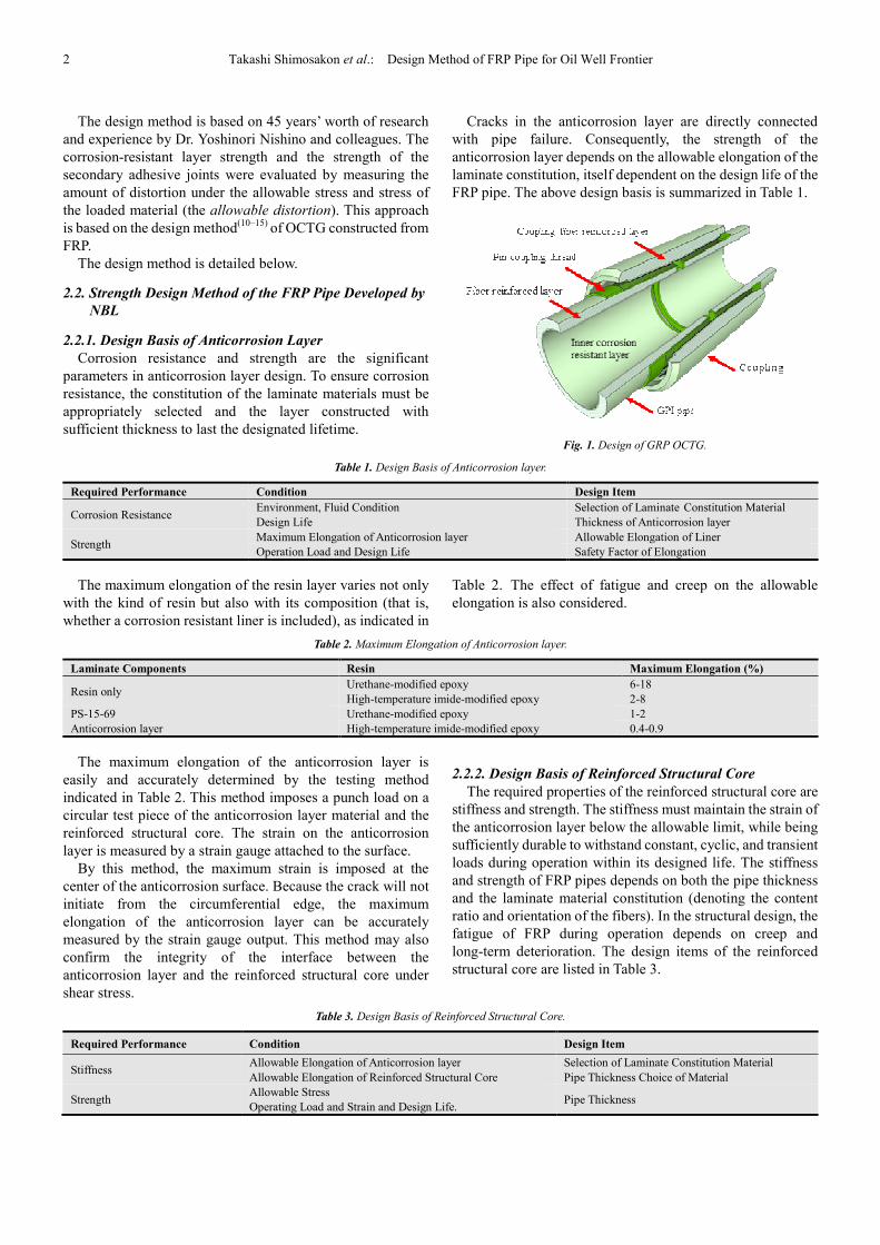
Cracks in the anticorrosion layer are directly connected
with pipe failure. Consequently, the strength of the
anticorrosion layer depends on the allowable elongation of the
laminate constitution, itself dependent on the design life of the
FRP pipe. The above design basis is summarized in Table 1.
Fig. 1. Design of GRP OCTG.
Table 1. Design Basis of Anticorrosion layer.
Required Performance Condition Design Item
Corrosion Resistance Environment, Fluid Condition Selection of Laminate Constitution Material
Design Life Thickness of Anticorrosion layer
Strength Maximum Elongation of Anticorrosion layer Allowable Elongation of Liner
Operation Load and Design Life Safety Factor of Elongation
The maximum elongation of the resin layer varies not only
with the kind of resin but also with its composition (that is,
whether a corrosion resistant liner is included), as indicated in
Table 2. The effect of fatigue and creep on the allowable
elongation is also considered.
Table 2. Maximum Elongation of Anticorrosion layer.
Laminate Components Resin Maximum Elongation (%)
Resin only Urethane-modified epoxy 6-18
High-temperature imide-modified epoxy 2-8
PS-15-69
Anticorrosion layer
Urethane-modified epoxy 1-2
High-temperature imide-modified epoxy 0.4-0.9
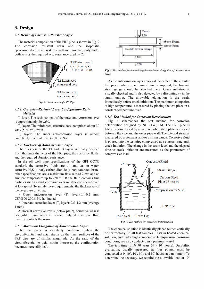
The maximum elongation of the anticorrosion layer is
easily and accurately determined by the testing method
indicated in Table 2. This method imposes a punch load on a
circular test piece of the anticorrosion layer material and the
reinforced structural core. The strain on the anticorrosion
layer is measured by a strain gauge attached to the surface.
By this method, the maximum strain is imposed at the
center of the anticorrosion surface. Because the crack will not
initiate from the circumferential edge, the maximum
elongation of the anticorrosion layer can be accurately
measured by the strain gauge output. This method may also
confirm the integrity of the interface between the
anticorrosion layer and the reinforced structural core under
shear stress.
2.2.2. Design Basis of Reinforced Structural Core
The required properties of the reinforced structural core are
stiffness and strength. The stiffness must maintain the strain of
the anticorrosion layer below the allowable limit, while being
sufficiently durable to withstand constant, cyclic, and transient
loads during operation within its designed life. The stiffness
and strength of FRP pipes depends on both the pipe thickness
and the laminate material constitution (denoting the content
ratio and orientation of the fibers). In the structural design, the
fatigue of FRP during operation depends on creep and
long-term deterioration. The design items of the reinforced
structural core are listed in Table 3.
Table 3. Design Basis of Reinforced Structural Core.
Required Performance Condition Design Item
Stiffness Allowable Elongation of Anticorrosion layer
Allowable Elongation of Reinforced Structural Core
Selection of Laminate Constitution Material
Pipe Thickness Choice of Material
Strength Allowable Stress
Operating Load and Strain and Design Life. Pipe Thickness
International Journal of Oil, Gas and Coal Engineering 2015; 3(1): 1-12 3
2.2.3. Design Basis of Joint
The pipe joint requires careful attention in the FRP piping
design. In most current FRP piping designs, the strength of the
FRP pipe joint is assumed to equal the adhesive strength of
two plates, based on the mean shear stress.
However, experiments and analyses carried out by NBL
Technovator Co., Ltd. have shown that the failure strength of
the joints largely depends on the shear stress concentration in
the adhesive layer. Therefore, multiplying the shear stress by a
safety factor, as implemented in current design methods, may
not be sufficiently conservative. As an example, the failure
pressure (or weeping pressure) of pipe joints measured in
hydrostatic tests is mainly controlled by the interfacial
strength between the roving cloth layer and the chopped strand
mat. In these tests, the mean shear stress reduces with
increasing adhesive length. This trend occurs because the
shear stress is concentrated around the edges of the adhesive
layer, and the stress concentration factor is a function of the
adhesive length and the stiffness of both layers.
The NBL design method allows either simplified analyses
by algebraic expressions or detailed analyses based on finite
element methods (FEMs). Simplified and detailed design
methods require different safety factors. The orthotropic
elastic properties of FRP are considered in the design analysis,
and the allowable stress and strain is decided for each material.
The optimal pipe thickness, geometry and dimensions are
determined by trial and error.
2.2.4. Calculation Basis
In NBL design, the elastic constants of the laminate
constituting materials are calculated by the linear law of
mixtures or some other well-known equation (the common
equations are listed in Appendix 2.) If necessary, equivalent
elastic constants of the laminated wall can be calculated by the
linear summation law.
In the simplified design method, the elastic constants
obtained by one of the above equations are substituted into the
algebraic expression shown in Section 3.
The detailed design method analyzes the stress by FEM. To
this end, NBL has developed the FRP-X software, which
performs two-dimensional plate, axisymmetric solid, and
three dimensional shell analyses of anisotropic materials on a
PC. FRP-X calculates the fiber direction and elastic modulus
element by element and outputs the stress and strain
components parallel and normal to the fiber. An auxiliary
program, FRP-MESH, automatically generates a proper mesh
from limited input data on the dimensions and material
composition of the joint. It also computes the elastic constants
of each material, the nodal coordinates, the node numbers
composing each element, and the fiber direction of each
element. Given the geometry and dimensions of the joint and
the laminate constitution, the optimized joint that satisfies the
stress and strain criteria at minimal cost is designed by trial
and error. For example, the most-recently submitted design of
the pipe joints is based on approximately 50 calculations,
varying the geometry and material in each case. Incidentally,
the complete set of analyses was completed in 10 hours,
including preparation of the input data.
NBL is currently focused on investigating the fatigue
strength and long-term deterioration of FRP materials and
structures and will propose a life prediction method within a
few years. Next, NBL plans to develop a CAD system for FRP
structural design. Combining FRP-X, FRP-MESH, and a post
processor, the CAD system will evaluate the FRP-X result
with reference to the design criteria. The system will also
include drawing software for displaying figures, tables, and
documents. Moreover, NBL has established a failure
simulation analysis method for the joint portion based on a
nonlinear spring model. This simplified nonlinear technique
simulates the entire failure process within a calculation time
only 20–30% higher than required for linear analysis.
2.3. Design Basis
2.3.1. Basic Pipe Specifications
The pipe is constructed from the following materials:
Inner surface: The anticorrosive specifications are
standardized in PS-15-69 (NBS).
Reinforced structure: Uses filament fiber reinforced core
plastic.
Outer surface: Stacked anticorrosion layers.
The basic pipe dimensions are listed in Table 4. The
nominal diameter is based on the inner diameter. The fitting
dimensions will be shown later.
Table 4. Basic Pipe Dimensions.
Tubing Pipe Casing & Line Pipe
D inch Pipe Length L (mm) Thread D inch Pipe Length L (mm) Thread
2-3/8
9500 mm GPI thread structure 8 round
5
9500 mm GPI thread structure 8 round
2-7/8 5-1/2
3-1/2 7
4-1/2 8-3/8
9-5/8
13-3/8
20
23-3/8
30
4 Takashi Shimosakon et al.: Design Method of FRP Pipe for Oil Well Frontier
The proper crest radius, total length of the thread root, and
the taper angle of the thread, determined by detailed stress and
strain analyses, may differ from the API standard.
2.3.2. Materials
・Raw materials
The raw materials are reinforced fiber: E glass fiber (0. 45
N/tex or higher); filament 23 µ; εmax 2%; laminated density 50
vol% or higher; circumferential direction: axial direction ratio
2:1, 1000–2000 g/m2; uniform filament length ± 0.1%;
combination of non-woven fabric and CSM 100200 g/m2; mat
irrigation surface of 13µ; 200 filament; 50 mm cut.
The resin is epoxy-modified; pH 2 or higher; εmax 4%–18%.
The usable temperature of resin (7 classes) ranges from its
thermal deformation temperature (60 °C) to 250°C.
・Quality control
Application: The material supplier is traceable by GPI16) or
by a guarantee program constructed for the QC system and
materials in accordance with ASME NCA-3800 and
NCA-4135.
GPI traceability standard: the pipe manufacturer should
enter the QC information of the material suppliers individual
product number, manufacturing information, and performance
test information, for traceability of the individual product.
The user constructs and installs the product and its
matching products, based on the traceability number and
conditions of use, enters the applicable construction
information, and applies the quality assurance traceability by
GPI signatories via the internet.
2.3.3. Design Scope
New oil well pipe design specifications (GPI load and
durability performance)
The new oil well pipe specifications in the GPI standard
stipulate a load of Grade 4 withstanding pressure and a Grade
6 heat resistance, as shown in the table below. The required
corrosion resistance is pH 2, and (omitting the details) the
short- and long-term endurance performance is 10 years and
50 years, respectively.
The standard length is 9.5 m, and the GPI standard
connection fittings are pin coupling screws. The oil well pipes
consist of tubing, casing and line pipe (see GPI standard.)
A GPI application product is named by its diameter,
withstanding pressure grade, and heat tolerance. For example,
Product 3-1/2M150 has a 3½-inch nominal diameter, a Grade
M withstanding pressure, and a heat design grade of 150 °C.
Table 5. GPI standard coupling (performance).
Withstanding
Pressure Grade Tubing & Casing Line Pipe
Designed
Pressure
Short-term
Load
10 years
Durability
50 years
Durability
E10 Tap water well, 100 m For water 10 MPa 5 MPa 3 MPa 2 MPa
E20 Tap water well, 200 m below For water 20 MPa 10 MPa 6 MPa 4 MPa
E40 Hot spring wells, 1,500-4,000 m Shale gas, CNG 40 MPa 20 MPa 12 MPa 8 MPa
G 2,000-6,000 m for oil field CNG gas tank 60 MPa 30 MPa 20 MPa 12 MPa
M 3,000-9,000 m for oil field Special purpose 1 80 MPa 40 MPa 26 MPa 16 MPa
H 4,000-12,000 m for oil field Special purpose 2 100 MPa 50 MPa 33 MPa 20 MPa
Withstanding
Temperature
(deg. C.)
-20 - 60 -10-80 0-110 25-250 25-200 Maximum 250
Temp. Grade 60 80 110 150 200 250
Product
Marking
Examples of products 2-7/8G-80: one coupling, in GPI tube with the other pin screw, outer diameter 2-7/8 inches, G grade
withstanding pressure, 100 degrees C. heat.
Examples of products 5(W)E20-80: in GPI tube with both ends pin screw, outer diameter 5 inches (casing inner tube), E20 grade
withstanding pressure, 80 degrees C. heat.
Examples of products 3-1/2M-100: 3-1/2 inches at GPI coupling, pressure-resistant M grade, 100 degrees C. heat.
Reference: API standard pipe design specifications
Long-term load: Internal pressures up to 3000 psi (21 MPa)
are imposed by the buried soil pressure, and self-restraint
loads are imposed by heavy thermal expansion and the piping
reaction force.
Short-term load (for buried piping only): This constitutes
the load associated with the track. The short-term maximum
load is 4000 psi (28 MPa).
Transient vacuum load: -1.0 kgf/cm2.
Other loads: These include the wind load, the vibration load
during an earthquake, and the restraint load due to anchoring.
Heat resistance: thermal stress and buckling; no special
provisions are made for these.
Corrosion resistance: acid degradation; no special
provisions are made for this.
Useful life: up to 30 years (medium-term 10 years). Under
varying load, the estimated number of repetitions should be
biased toward safety. If many repetitions are expected but their
number is difficult to estimate, the repetition number should
be set to 107.
・Evaluation
To confirm acceptable stress and strain under long-term
loading, the fatigue, creep, and aging properties are evaluated.
All combinations of short-term loads, which may act as
long-term loads, are evaluated in the same manner.
・Other checks
GPI standard compliant.
International Journal of Oil, Gas and Coal Engineering 2015;
3. Design
3.1. Design of Corrosion-Resistant Layer
The material composition of the FRP pipe is shown in Fig. 2.
The corrosion resistant resin and the isopthalic
epoxy-modified resin system (urethane, novolac, polyimide)
both satisfy the required acid resistance of pH = 2
Fig. 2. Construction of FRP Pipe
3.1.1. Corrosion-Resistant Layer Configuration Resin
Material
T1 layer: The resin content of the outer anti
is approximately 80 wt%.
T2 layer: The reinforced structure core comprises about 30
wt% (50% vol) resin.
T3 layer: The inner anti-corrosion layer is almost
completely made of resin (~100 wt%).
3.1.2. Thickness of Anti-Corrosion Layer
The thickness of the T1 and T3 layers
from the inner diameter of the FRP pipe, the
and the required abrasion resistance.
In the oil well pipe specifications of the GPI OCTG
standard, the corrosive fluids are oil and gas in water,
corrosive H2S (1 bar), carbon dioxide (1 bar) saturated brine;
other specifications are a maximum flow rate of 2 m/s and an
ambient temperature up to 250 °C. If the fluid contains fine
particles such as sand, corrosive wear must be considered even
at low speed. To satisfy these requirements, the thicknesses of
the layers are given as:
・ Outer anticorrosion layer (T1 layer
CSM100-200#1Ply laminated
・Inner anticorrosion layer (T3 layer): 0.5
1 mm).
At normal corrosive levels (below pH 2)
negligible. Lamination is needed only
directly contacts the resin.
3.1.3. Maximum Elongation of Anticorrosion Layer
The test piece is circularly configured when the
circumferential and axial strains on the inner surfaces of the
FRP pipe are of similar magnitude. As the ratio
circumferential to axial strain increases, the configuration
becomes more elliptical.
International Journal of Oil, Gas and Coal Engineering 2015; 3(1): 1-12
The material composition of the FRP pipe is shown in Fig. 2.
The corrosion resistant resin and the isopthalic
modified resin system (urethane, novolac, polyimide)
required acid resistance of pH = 2.
Construction of FRP Pipe.
Resistant Layer Configuration Resin
The resin content of the outer anti-corrosion layer
core comprises about 30
corrosion layer is almost
is finally decided
the corrosive fluids,
In the oil well pipe specifications of the GPI OCTG
oil and gas in water,
S (1 bar), carbon dioxide (1 bar) saturated brine;
pecifications are a maximum flow rate of 2 m/s and an
ambient temperature up to 250 °C. If the fluid contains fine
particles such as sand, corrosive wear must be considered even
at low speed. To satisfy these requirements, the thicknesses of
layer):0.1-0.2 mm,
0.5–1.2 mm (average
corrosive levels (below pH 2), corrosive wear is
if corrosive fluid
Maximum Elongation of Anticorrosion Layer
he test piece is circularly configured when the
circumferential and axial strains on the inner surfaces of the
FRP pipe are of similar magnitude. As the ratio of the
circumferential to axial strain increases, the configuration
Fig. 3. Test method for determining the
layer.
As the anticorrosion layer cracks
test piece, where maximum strain is imposed, the bi
strain gauge should be attached there. Crack initiation is
visually checked and is also detected by a discontinuity in the
strain output. The allowable elongation is the
immediately before crack initiation. The maximum elongation
at high temperature is measured by placing the test piece in a
constant-temperature oven.
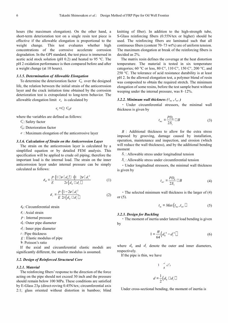
3.1.4. Test Method for Corrosion Deterioration
Fig. 4 schematizes the test method for corrosion
deterioration designed by NBL Co., Ltd.
laterally compressed by a vice. A carbon steel plate is inserted
between the vice and the outer pipe wall. The internal strain is
measured by a compass and/or a strain gauge. Corrosive fluid
is poured into the test pipe compressed at a constant rate until
crack initiation. The change in the strain level and the elapsed
time to crack initiation are measured as the parameters of
compressive load.
Fig. 4. Test method for corrosion Deterioration
The chemical solution is identically placed (either vertically
or horizontally) in all test samples. Tests in heated chemical
solution, and under high-temperature high
conditions, are also conducted in a pressure vessel
The test time is 10–50 years (4 × 10
evaluation, usually measured at four points, must be
conducted at 0, 101, 10
2, 10
3, and 10
determine the accuracy, we require the allowable load at 10
5
the maximum elongation of anticorrosion
the anticorrosion layer cracks at the center of the circular
test piece, where maximum strain is imposed, the bi-axial
strain gauge should be attached there. Crack initiation is
visually checked and is also detected by a discontinuity in the
strain output. The allowable elongation is the strain
immediately before crack initiation. The maximum elongation
at high temperature is measured by placing the test piece in a
Method for Corrosion Deterioration
the test method for corrosion
erioration designed by NBL Co., Ltd. The FRP pipe is
laterally compressed by a vice. A carbon steel plate is inserted
between the vice and the outer pipe wall. The internal strain is
measured by a compass and/or a strain gauge. Corrosive fluid
to the test pipe compressed at a constant rate until
crack initiation. The change in the strain level and the elapsed
time to crack initiation are measured as the parameters of
method for corrosion Deterioration.
al solution is identically placed (either vertically
or horizontally) in all test samples. Tests in heated chemical
temperature high-pressure corrosion
conditions, are also conducted in a pressure vessel.
rs (4 × 10⁵ hours). Durability
evaluation, usually measured at four points, must be
, and 104 hours, at a minimum. To
determine the accuracy, we require the allowable load at 104
6 Takashi Shimosakon
hours (the maximum elongation). On the other han
short-term deterioration test on a single resin test piece is
effective if the allowable elongation is proportional to the
weight change. This test evaluates whether high
concentrations of the corrosive accelerate corrosion
degradation. In the GPI standard, the test piece is immersed in
acetic acid stock solution (pH 0.2) and heated to 95 °C. The
pH 2 oxidation performance is then compared before and after
a weight change (at 10 hours).
3.1.5. Determination of Allowable Elongation
To determine the deterioration factor
life, the relation between the initial strain of the anticorrosion
layer and the crack initiation time obtained by the corrosion
deterioration test is extrapolated to long-term behavior. The
allowable elongation limit is calculated by
where the variables are defined as follows:
: Safety factor
: Deterioration factor
: Maximum elongation of the anticorrosive layer
3.1.6. Calculation of Strain on the Anticorrosion Layer
The strain on the anticorrosion layer is calcu
simplified equation or by detailed FEM analysis. This
specification will be applied to crude oil piping; therefore the
important load is the internal load. The strain on the inner
anticorrosion layer under internal pressure can be simply
calculated as follows:
: Circumferential strain
: Axial strain
: Internal pressure
: Outer pipe diameter
: Inner pipe diameter
: Pipe thickness
: Elastic modulus of pipe
: Poisson’s ratio
If the axial and circumferential elastic moduli are
significantly different, the smaller modulus is assumed
3.2. Design of Reinforced Structural Core
3.2.1. Material
The reinforcing fibers’ response to the direction of the force
acting on the pipe should not exceed 30 inch and the pressu
should remain below 100 MPa. These conditions are satisfied
by E-Glass 23µ (direct-roving 0.45N/tex; circumferential axis
2:1; glass oriented without distortion in bamboo; blind
DC
ae
DCa Se C e= ・
sC
DC
e
( ) (( )2 2
0
0
1 1 2
2i
d dP
E t d dθ
ν νε
+ + −=
+
( )( )
2
0
1 2
2
i
i
dP
E t d d
νε
−=
+ℓ
θεεℓ
P
0d
id
t
Eν
Takashi Shimosakon et al.: Design Method of FRP Pipe for Oil Well Frontier
hours (the maximum elongation). On the other hand, a
term deterioration test on a single resin test piece is
effective if the allowable elongation is proportional to the
weight change. This test evaluates whether high
concentrations of the corrosive accelerate corrosion
ndard, the test piece is immersed in
acetic acid stock solution (pH 0.2) and heated to 95 °C. The
pH 2 oxidation performance is then compared before and after
Determination of Allowable Elongation
over the designed
life, the relation between the initial strain of the anticorrosion
layer and the crack initiation time obtained by the corrosion
term behavior. The
is calculated by
anticorrosive layer
Anticorrosion Layer
The strain on the anticorrosion layer is calculated by a
simplified equation or by detailed FEM analysis. This
specification will be applied to crude oil piping; therefore the
important load is the internal load. The strain on the inner
anticorrosion layer under internal pressure can be simply
(1)
(2)
elastic moduli are
significantly different, the smaller modulus is assumed.
The reinforcing fibers’ response to the direction of the force
acting on the pipe should not exceed 30 inch and the pressure
should remain below 100 MPa. These conditions are satisfied
roving 0.45N/tex; circumferential axis
2:1; glass oriented without distortion in bamboo; blind
knitting of fiber). In addition to the high
S-Glass reinforcing fibers (0.55N/tex or higher) should be
used. The reinforcing fibers are laminated such that all
continuous fibers (content 70–73 wt%) are of uniform tension.
The maximum elongation at break of the reinforcing fibers is
decided as 2%.
The matrix resin defines the coverage at the heat distortion
temperature. The material is tested in six temperature
categories; 60 °C or less, 80 C°, 110 C°, 150 C°, 200 °C, and
250 °C. The tolerance of acid resistance durability is at least
pH 2. In the allowed elongation
was composited to obtain the required stretch. The minimum
elongation of some resins, before the test sample burst without
weeping under the internal pressure, was 8
3.2.2. Minimum wall thickness
・ Under circumferential stressors, the minimal wall
thickness is given by
mct B= +
B : Additional thickness to allow for the extra stress
imposed by grooving, damage caused by installation,
operation, maintenance and inspection, and erosion (which
will reduce the wall thickness), and by the
moment
Sℓ : Allowable stress under longitudinal tension
cS : Allowable stress under circumferential tension
・Under longitudinal stressors, the minimal wall thickness
is given by
mt Bℓ
・The selected minimum wall thickness is
or (5).
m mc mt Max t t=
3.2.3. Design for Buckling
・The moment of inertia under lateral load
by
( 064
d dπΙ = −
where 0d and id denote the outer and inner diameters,
respectively.
If the pipe is thin, we have
(1
2d d d= +
Under cross-sectional bending, the moment of inertia is
)2 21 1 2i
i
d d
E t d d
ν ν
.: Design Method of FRP Pipe for Oil Well Frontier
knitting of fiber). In addition to the high-strength tube,
ing fibers (0.55N/tex or higher) should be
used. The reinforcing fibers are laminated such that all
73 wt%) are of uniform tension.
The maximum elongation at break of the reinforcing fibers is
efines the coverage at the heat distortion
temperature. The material is tested in six temperature
categories; 60 °C or less, 80 C°, 110 C°, 150 C°, 200 °C, and
250 °C. The tolerance of acid resistance durability is at least
pH 2. In the allowed elongation test, a polymer blend of resin
was composited to obtain the required stretch. The minimum
elongation of some resins, before the test sample burst without
weeping under the internal pressure, was 8–12%.
Minimum wall thickness ( mct , mt ℓ )
Under circumferential stressors, the minimal wall
0
2mc
c
PDt B
S= + (3)
to allow for the extra stress
imposed by grooving, damage caused by installation,
operation, maintenance and inspection, and erosion (which
will reduce the wall thickness), and by the additional bending
longitudinal tension
circumferential tension
Under longitudinal stressors, the minimal wall thickness
0
2m
PDt B
S= +
ℓ
ℓ
(4)
The selected minimum wall thickness is the larger of (4)
( ),m mc mt Max t t=ℓ (5)
The moment of inertia under lateral load bending is given
)4 4
064
id dΙ = − (6)
denote the outer and inner diameters,
)0
1
2id d d= +
sectional bending, the moment of inertia is
International Journal of Oil, Gas and Coal Engineering 2015; 3(1): 1-12 7
( )3
212 1
bt
νΙ =
− (7)
where t is the pipe thickness, and b is the length of the cylinder
・Moment of inertia of a stiffened cylinder
Assuming that the circumferential and axial stiffness
sufficiently guard against external pressure buckling and axial
buckling respectively, we have
*
0
s
eL
ΙΙ = Ι + (8)
*Ι : Equivalent moment of inertia of cylinder reinforced
with stiffener
sΙ : Moment of inertia of stiffener
0Ι : Moment of inertia of cylinder alone
eL : = I(axial buckling) =
( )0
1
2 4
2,
3 1
d tMin L
ν
−
(circumferential buckling)
L : Interval of the stiffener
・The limiting pressure for axial buckling is given by
( )22 2 2
2 2 22 2
4 1
12 1cr
F
Em E tP
Sm d
θππν
= + −
ℓℓ
ℓ (9)
Eℓ : Axial elastic modulus
Eθ : Circumferential elastic modulus
ν : Poisson’s ratio
ℓ : Length of cylinder (interval of stiffener) t : Pipe wall thickness
d : Diameter of cylinder
FS : Safety factor(=3.0)
m : Integer
・The limiting external pressure for buckling (excluding
the burial pressure) is given by
c
dL kd
t= > L :
General buckling needs to be considered when
k = 1.11 for ν = 0.3
2 3
4 3/yL t
d d Eθ
σλ =
(10)
If 0.9λ ≥ , unstable buckling (shell plate buckling or
general buckling) must be considered.
If λ< 0.9 , the axisymmetric collapse is calculated.
2y
PD
tϕ
σ= (11)
Unstable buckling may occur if ϕ< 0.8, and
axisymmetrical collapse is possible if ϕ>1; both scenarios
need to be checked.
1) The shell-plate buckling pressure is computed as
follows:
(a) ( )2
4.72
/L D<
D
t
( )
2.52.6
/ 0.45 /cr
E tP
DL D t D
= − (12)
(b)
2
3.28L
D
<
D
t & ( )2
2.1
/L D<
D
t< ( )2
4.72
/L D
( )
2.52.6
/ 0.9 0.5 /cr
E tP
DfL D f t D
= − − (13)
f: Coefficient depending on the constraint imposed by the
boundary
Nθ =1
2f PD
(c)
2
0.524L
D
<
D
t<
2
3.28L
D
( )( )
( )2 42 2
2 2 22 2
0.4484 /3.6151.216
2.432 / 1.621 /cr
D LE t t DP
D D LD L D L
= + + + +
(14)
(d) D
t<
2
0.524L
D
3
2.2cr
tP E
D
=
(15)
2) Elastic general buckling pressure
( ) [ ]( ) ( )
2 40
3 2' 2 2 2 2
8 12
2 1 0.5
s b
cr
eb b
n E L tP E
DD L f n n
λ
λ λ
− Ι + Ι = + − + +
(16)

8 Takashi Shimosakon et al.: Design Method of FRP Pipe for Oil Well Frontier
02
b
D
L
πλ = 0L : Total length of cylinder
' 1
1f
fA
tL
=+
fA : Cross-section area of stiffener
where shell plate buckling may be critical, the stiffener will
be sufficiently rigid to provide a >10% safety margin against
buckling.
3) Axisymmetric collapse is given by
2 y
cr
tP
d
σ= (17)
① Safety factor
The buckling pressure limit of the buried pipe is
*
3
132 ' '
cr w
F
EP R B E
S d
Ι= (18)
1 0.33 w
w
hR
h= − : Coefficient of water buoyancy
wh : Water height from the top of the pipe
h : Ground height from the top of the pipe
'B : Coefficient of elastic support (=0.065
1
1 4H
e−+
)
H : Burial depth above the top of the pipe (ft)
'E : Elastic modulus of soil *EΙ : Equivalent bending rigidity of the pipe
d : Pipe diameter
FS : Safety factor (=3.0)
3.2.4. Design for Long-Term Load
Long-term load includes the internal pressure, the pressure
due to soil weight (which acts on buried pipes only), and the
reaction and constrained forces on the pipe caused by thermal
expansion.
0 0.754
CA
m
PD iMiMS
t Z Z+ + ≤
ℓ (19)
P : Internal pressure - soil pressure
0D : Outer pipe diameter
mt : Thickness of reinforced structural core
Z : Section modulus of pipe, (=2
4
mD tπ, D: Mean dia.)
i : Stress intensification factor (0.75i ≧ 1.0)
AM : Bending moment due to the weight load and other
sustained loads
CM : Bending moment imposed on the piping system by
thermal expansion, internal pressure deformation and anchor
displacement
3.2.5. Design for (Short-Term Load) + (Long-Term Load)
Short-term load includes transient over-pressure, truck load
(on buried pipes), and other loads such as seismic, wind, and
impact loads. As long-term and short-term loading can
simultaneously occur, both load classes are combined in the
design.
( )max 0 0.75 1.24
A B C
m
M MP D iMi S
t Z Z
++ + ≤
ℓ (20)
maxP : Peak pressure
BM : Bending moment imposed by transient over-pressure,
earthquakes, strong wind, impact and trucks passing (above
buried pipes only)
3.2.6. Detailed Analysis of Piping
If criteria (4) and (5) are not satisfied, a detailed stress
analysis of the entire piping system is recommended. The
design should consider the rationalized allowable stress
obtained in the detailed analysis.
3.3 Design of Joint
Provided that the reinforced structural core is designed
according to the criteria described in Section 3.2, the joint
portion will not fail under normal stress. However, failure of
the joint portion can initiate from the adhered layer;
specifically, the interface between the mat and roving layers.
Therefore, the adhered layer should be designed such that the
actual shear stress is below the allowable level.
The shear stress of the adhesive layer is highest at the edge
of the secondary portion, as indicated in Fig. 6.
( )( )
1 1 2 2
1
1 1 2 2
cosh
sinh
FC E t E t C
d E t E t Cτ
π+
=+
ℓ
ℓ (21)
( )( )
1 1 2 2
2
1 1 2 2
cosh
sinh
FC E t C E t
d E t E t Cτ
π+
=+
ℓ
ℓ (22)
( )max 1 2,Maxτ τ τ= (23)
F : Axial load on the joint portion
0
1 1 2 2
1 1GC
H E t E t
= +
(24)
0G : Shear modulus of the adhesive layer
H : Thickness of adhesive layer
1E , 2E : Elastic modulus of material 1.2
1t , 2t : Pipe thickness of range 1.2
ℓ : Length of adhesive layer
d : Diameter of adhesive layer
・ For long-term load
max cSτ ≤ℓ
International Journal of Oil, Gas and Coal Engineering 2015; 3(1): 1-12 9
・ For (short-term load) +(long-term load)
max1.2
cSτ ≤ℓ
cSℓ : Allowable shear stress
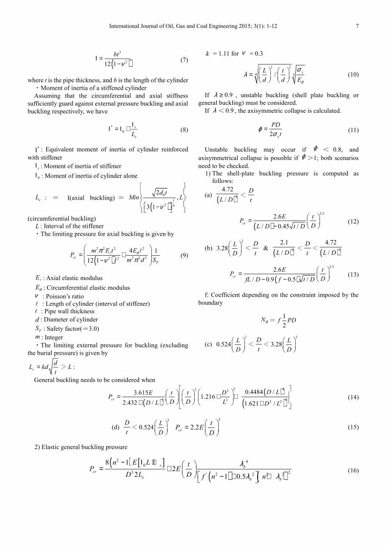
Fig. 5. Joint model.
・As stated above, for (short-term load) + (long-term load)
we have
max1.2
cSτ ≤ℓ
When conducting a detailed stress analysis of the joints, the
results should determine the allowable stress in the design.
In determining the smallest allowable shear stress, the joint
surface is assumed to taper at 1/16. Other parameters are ℓ/ 2t
= 8–10 and I = 2–4 mm. The optimal screw on the joint surface
is an 8-round screw.
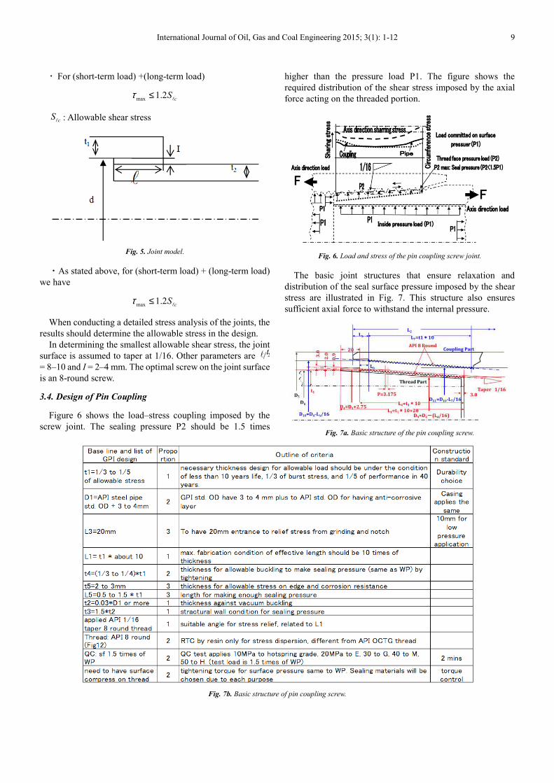
3.4. Design of Pin Coupling
Figure 6 shows the load–stress coupling imposed by the
screw joint. The sealing pressure P2 should be 1.5 times
higher than the pressure load P1. The figure shows the
required distribution of the shear stress imposed by the axial
force acting on the threaded portion.
Fig. 6. Load and stress of the pin coupling screw joint.
The basic joint structures that ensure relaxation and
distribution of the seal surface pressure imposed by the shear
stress are illustrated in Fig. 7. This structure also ensures
sufficient axial force to withstand the internal pressure.
Fig. 7a. Basic structure of the pin coupling screw.
Fig. 7b. Basic structure of pin coupling screw.
10 Takashi Shimosakon et al.: Design Method of FRP Pipe for Oil Well Frontier
The basic structure of the joints using an 8-round screw
exploits the characteristics of an FRP-specific ratio rigid pipe
by providing a corrosion-resistant layer resin layer on the
internal surface that contacts the fluid. Stress relaxation is
necessary such as to transmit the pressure load on the sealing
surface.
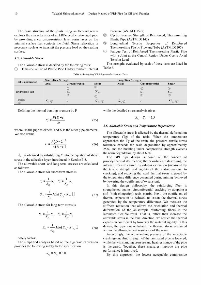
3.5. Allowable Stress
The allowable stress is decided by the following tests:
① Time-to-Failure of Plastic Pipe Under Constant Internal
Pressure (ASTM D1598)
② Cyclic Pressure Strength of Reinforced, Thermosetting
Plastic Pipe (ASTM D2143)
③ Longitudinal Tensile Properties of Reinforced
Thermosetting Plastic Pipe and Tube (ASTM D2105)
④ Fatigue Test of Reinforced Thermosetting Plastic Pipe
with a Joint at the Central Region Under Cyclic Axial
Tension Load
The strengths evaluated by each of these tests are listed in
Table 6.
Table 6. Strength of FRP Pipe under Various Tests.
Test Classification Short-Time Strength Long-Time Strength
Axial Circumferential Shear Axial Circumferential Shear
Hydrostatic Test
①
Sc1
②
①
1' cSℓ
②
①
Sℓ2
②
①
Sℓc2
②
Tension
Test 1Sℓ ③ -
1' cSℓ ③
2Sℓ ④ -
2' cSℓ ④
Defining the internal bursting pressure by P,
( )2
c
P D tS
t
−= (25)
where t is the pipe thickness, and D is the outer pipe diameter.
We also define
( )( )
22
4
P D tF
D t
−=
− (26)
cSℓ is obtained by substituting F into the equation of shear
stress in the adhesive layer, introduced in Section 3.3.
The allowable short- and long-term stresses are calculated
as follows:
The allowable stress for short-term stress is
1
1
1
F
S SS
=ℓ ℓ
1
1
1c c
F
S SS
=
( )1 1
1
1'c c c
F
S Min S SS
=ℓ ℓ ℓ
・ (27)
The allowable stress for long-term stress is
2
2
1
F
S SS
=ℓ ℓ
2
2
1c c
F
S SS
=
( )2 2
2
1'c c c
F
S Min S SS
=ℓ ℓ ℓ
・ (28)
Safely factor:
The simplified analysis based on the algebraic expression
provides the following safety factor specification
1 23.0
F FS S= =
while the detailed stress analysis gives
1 22.5
F FS S= =
3.6. Allowable Stress and Temperature Dependence
The allowable stress is affected by the thermal deformation
temperature (Tg) of the resin. When the temperature
approaches the Tg of the resin, the pressure tensile stress
tolerance exceeds the resin degradation by approximately
25%, and the buckling under compressive strength exceeds
the resin degradation by about 60%.
The GPI pipe design is based on the concept of
priority-thermal destruction; the priorities are destroying the
internal pressure caused by oil–gas extraction (measured by
the tensile strength and rigidity of the matrix material to
cracking), and reducing the axial thermal stress imposed by
the temperature difference generated during mining (achieved
by lowering the coefficient of expansion).
In this design philosophy, the reinforcing fiber is
strengthened against circumferential cracking by adopting a
soft (high elongation) resin matrix. Next, the coefficient of
thermal expansion is reduced to lessen the thermal stress
generated by the temperature difference. We measure the
stiffness reduction that allows the orientation and thermal
deformation of the anisotropic reinforcing fibers in the
laminated flexible resin. That is, rather than increase the
allowable stress in the axial direction, we reduce the thermal
expansion coefficient by lowering the material rigidity. In this
design, the pipe can withstand the thermal stress generated
within the allowable heat resistance of the resin.
Accordingly, the withstanding pressure of the acceptable
crushing–buckling strength of the laminated pipe is lowered,
while the withstanding pressure and heat resistance of the pipe
is increased. Together, these measures improve the pipe
performance is improved.
By this approach, the lowest acceptable compressive
International Journal of Oil, Gas and Coal Engineering 2015;
strength is about 40% of the axial tensile strength
from the design and test results (100 MPa). The heat
degradation is reduced by 10% at the maximum allowable
temperature, and finally contributes around 30% of the
allowable stress (75 MPa). Thus we have designed an oil well
pipe that can withstand the target internal pressure of 100 MPa,
a maximum temperature difference of 250°C, and a corrosion
resistance of pH 2. The expected durability of
is 50 years.
4. Quality Assurance
The quality assurance program of the OCTG interpolates
the IC chip along with the visible character information and
the bar code information display, which are
outside of the pipe surface with the internal pipe surface.
The design information from which the final material load
test was devised and the specified durability period is
maintained, is provided in the database. The information can
be confirmed via the Internet, according to the G
traceability16)
provided by a third party or by the API standard
quality assurance testing program. Detailed
omitted.
In the GPI quality assurance program
traceability may be subjected to a preferred insurance system,
such as PL liability insurance guarantees.
5. Conclusion
This work has described the basic design theory by which
we produce strong, durable (expected lifetime = 50 y) oil well
pipes. The pipes can withstand a pressure of 100 MPa and a
depth of 7000 m. In addition, they are heat-
and anti-corrosive to a pH of 2. The material constants derived
by the applied stress analysis are presented in the Appendix
(the theoretical details of the analysis are omitted).
In designing the pipe deployment, we drew on long
research by the authors, some of which is provided in the
reference list.
Fig. 8. Examples of products manufactured under the proposed
The present strength design method for FRP pipes in new
oil wells is based on the design logic of OCTG in the GPI
technology standard. Examples of pipes satisfy
standards are photographed in Fig. 8. These pipes have been
commercially available since 2009 and have made a
International Journal of Oil, Gas and Coal Engineering 2015; 3(1): 1-12
strength is about 40% of the axial tensile strength determined
from the design and test results (100 MPa). The heat
degradation is reduced by 10% at the maximum allowable
ibutes around 30% of the
allowable stress (75 MPa). Thus we have designed an oil well
pipe that can withstand the target internal pressure of 100 MPa,
a maximum temperature difference of 250°C, and a corrosion
resistance of pH 2. The expected durability of the oil well pipe
OCTG interpolates
the visible character information and
, which are visible from
with the internal pipe surface.
from which the final material load
test was devised and the specified durability period is
maintained, is provided in the database. The information can
be confirmed via the Internet, according to the GPI
provided by a third party or by the API standard
quality assurance testing program. Detailed information is
In the GPI quality assurance program, the product
traceability may be subjected to a preferred insurance system,
This work has described the basic design theory by which
we produce strong, durable (expected lifetime = 50 y) oil well
pipes. The pipes can withstand a pressure of 100 MPa and a
-resistant to 250°C
corrosive to a pH of 2. The material constants derived
by the applied stress analysis are presented in the Appendix
(the theoretical details of the analysis are omitted).
we drew on long-term
research by the authors, some of which is provided in the
Examples of products manufactured under the proposed design theory.
The present strength design method for FRP pipes in new
oil wells is based on the design logic of OCTG in the GPI
technology standard. Examples of pipes satisfying the GPI
standards are photographed in Fig. 8. These pipes have been
commercially available since 2009 and have made a
significant contribution to the market
PS: For OCTG applications
standard. (http://gpi-pipe.org)
Acknowledgement
This manuscript is certified by
Institute (GPI) which provided
GPI homepage (URL: http://www.g
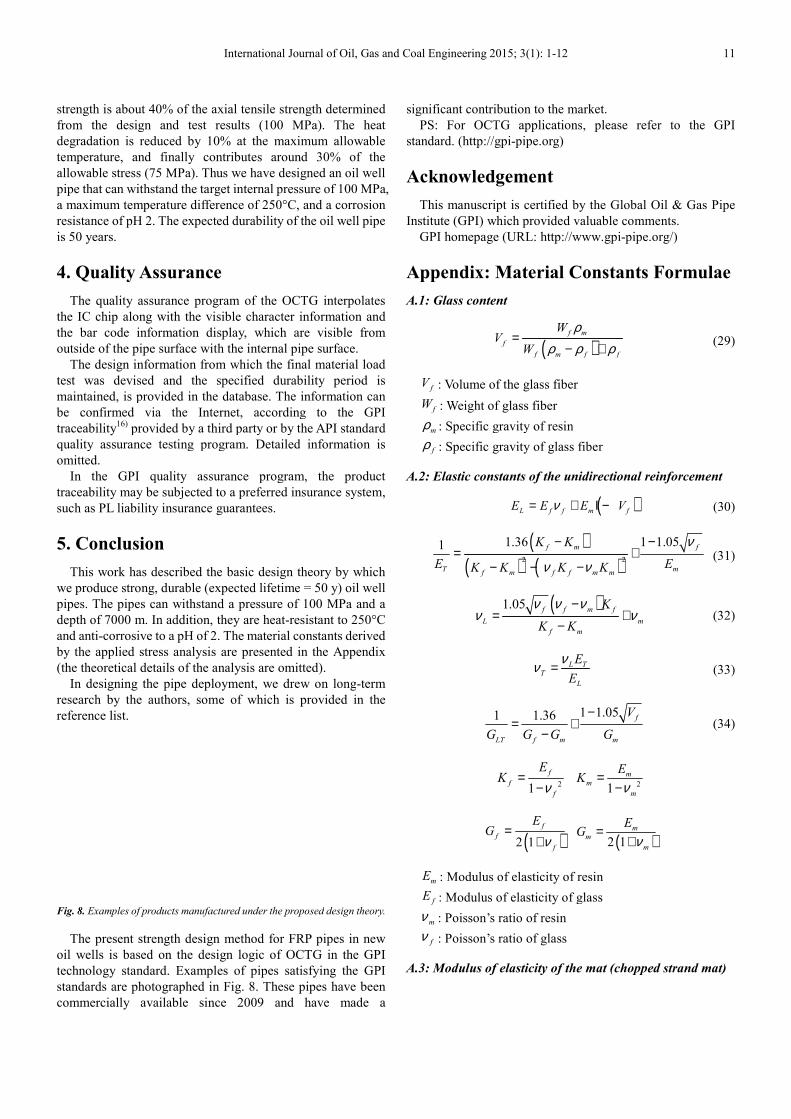
Appendix: Material Constants Formula
A.1: Glass content
(f m
f
f m f f
WV
W ρ ρ ρ=
− +
fV : Volume of the glass fiber
fW : Weight of glass fiber
mρ : Specific gravity of resin
fρ : Specific gravity of glass fiber
A.2: Elastic constants of the unidirectional
L f f m fE E E Vν= + Ι −
(( ) (2 2
1.36 1 1.051 f m f
T mf m f f m m
K K
E EK K K Kν ν
− −= +
− − −
(1.05 f f m f
L m
f mK K
ν ν νν ν
−= +
−
L T
TE
νν =
1 1.36
LT f m mG G G G
= +−
21
f
f
f
EK
ν=
−
( )2 1
f
f
f
EG
ν=
+
mE : Modulus of elasticity of resin
fE : Modulus of elasticity of glass
mν : Poisson’s ratio of resin
fν : Poisson’s ratio of glass
A.3: Modulus of elasticity of the
11
significant contribution to the market.
ons, please refer to the GPI
This manuscript is certified by the Global Oil & Gas Pipe
valuable comments.
http://www.gpi-pipe.org/)
Appendix: Material Constants Formulae
)f m
f m f f
W ρρ ρ ρ− + (29)
of the glass fiber
gravity of resin
Specific gravity of glass fiber
unidirectional reinforcement
( )L f f m fE E E V= + Ι − (30)
))2 2
1.36 1 1.05f m f
T mf m f f m m
K K
E EK K K K
ν
ν ν
− −= +
− − − (31)
)f f m f
L m
f m
K
K K
ν ν νν ν
−= + (32)
L T
L
E
E
ν (33)
1 1.051 1.36 f
LT f m m
V
G G G G
−= + (34)
2 21
m
m
m
EK
ν=
−
( )2 1
m
m
m
EG
ν=
+
of resin
of glass
of the mat (chopped strand mat)
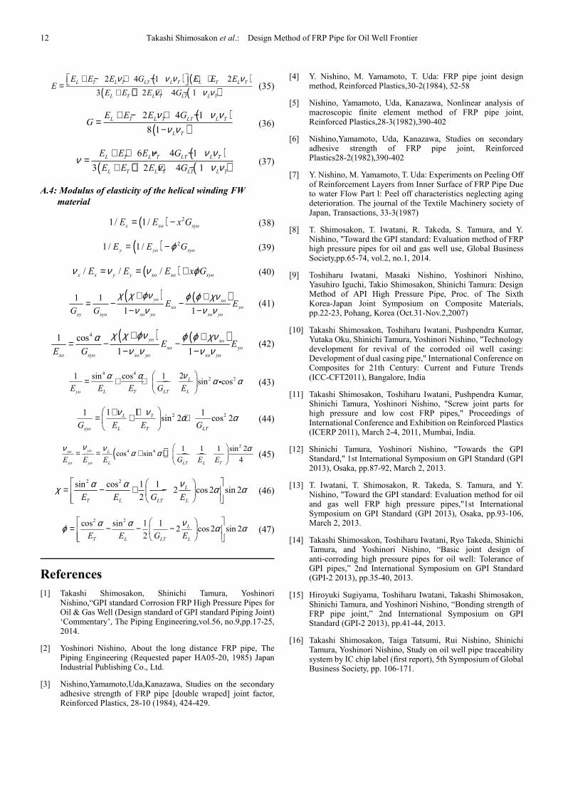
12 Takashi Shimosakon et al.: Design Method of FRP Pipe for Oil Well Frontier
( ) ( )( ) ( )2 4 1 2
3 2 4 1
L T L T LT L T L T L T
L T L T LT L T
E E E G E E EE
E E E G
ν ν ν νν ν ν
+ − + − + + =+ + + −
(35)
( )( )
2 4 1
8 1
L T L T LT L T
L T
E E E GG
ν ν νν ν
+ − + −=
− (36)
( )( ) ( )
6 4 1
3 2 4 1
L T L T LT L T
L T L T LT L T
E E E G
E E E G
ν ν νν
ν ν ν+ + − −
=+ + + −
(37)
A.4: Modulus of elasticity of the helical winding FW
material
( ) 21/ 1/x xo xyoE E x G= − (38)
( ) 21 / 1 /y yo xyoE E Gϕ= − (39)
( )/ / /x x y y xo xo xyoE E E x Gν ν ν ϕ= = + (40)
( ) ( )1 1
1 1
yo xo
xo yo
xy xyo xo yo xo yo
E EG G
χ χ ϕν ϕ ϕ χνν ν ν ν+ +
= − −− −
(41)
( ) ( )41 cos
1 1
yo xo
xo yo
xo xyo xo yo xo yo
E EE G
χ χ ϕν ϕ ϕ χναν ν ν ν+ +
= − −− −
(42)
4 42 221 sin cos 1
sin cosL
yo L T LT LE E E G E
να α α α
= + + −
i (43)
2 21 11 1sin 2 cos 2L T
xyo L T LTG E E G
ν ν α α + +
= + +
(44)
( )2
4 4 1 1 1 sin 2cos sin
4
yoxo L
xo yo L LT L TE E E G E E
νν ν αα α
= = + + − −
(45)
2 2sin cos 1 12 cos 2 sin 2
2
L
T L LT LE E G E
να αχ α α
= − + −
(46)
2 2cos sin 1 12 cos 2 sin 2
2
L
T L LT LE E G E
να αϕ α α
= − − −
(47)
References
[1] Takashi Shimosakon, Shinichi Tamura, Yoshinori Nishino,“GPI standard Corrosion FRP High Pressure Pipes for Oil & Gas Well (Design standard of GPI standard Piping Joint) ‘Commentary’, The Piping Engineering,vol.56, no.9,pp.17-25, 2014.
[2] Yoshinori Nishino, About the long distance FRP pipe, The Piping Engineering (Requested paper HA05-20, 1985) Japan Industrial Publishing Co., Ltd.
[3] Nishino,Yamamoto,Uda,Kanazawa, Studies on the secondary adhesive strength of FRP pipe [double wraped] joint factor, Reinforced Plastics, 28-10 (1984), 424-429.
[4] Y. Nishino, M. Yamamoto, T. Uda: FRP pipe joint design method, Reinforced Plastics,30-2(1984), 52-58
[5] Nishino, Yamamoto, Uda, Kanazawa, Nonlinear analysis of macroscopic finite element method of FRP pipe joint, Reinforced Plastics,28-3(1982),390-402
[6] Nishino,Yamamoto, Uda, Kanazawa, Studies on secondary adhesive strength of FRP pipe joint, Reinforced Plastics28-2(1982),390-402
[7] Y. Nishino, M. Yamamoto, T. Uda: Experiments on Peeling Off of Reinforcement Layers from Inner Surface of FRP Pipe Due to water Flow Part l: Peel off characteristics neglecting aging deterioration. The journal of the Textile Machinery society of Japan, Transactions, 33-3(1987)
[8] T. Shimosakon, T. Iwatani, R. Takeda, S. Tamura, and Y. Nishino, "Toward the GPI standard: Evaluation method of FRP high pressure pipes for oil and gas well use, Global Business Society,pp.65-74, vol.2, no.1, 2014.
[9] Toshiharu Iwatani, Masaki Nishino, Yoshinori Nishino, Yasuhiro Iguchi, Takio Shimosakon, Shinichi Tamura: Design Method of API High Pressure Pipe, Proc. of The Sixth Korea-Japan Joint Symposium on Composite Materials, pp.22-23, Pohang, Korea (Oct.31-Nov.2,2007)
[10] Takashi Shimosakon, Toshiharu Iwatani, Pushpendra Kumar, Yutaka Oku, Shinichi Tamura, Yoshinori Nishino, "Technology development for revival of the corroded oil well casing: Development of dual casing pipe," International Conference on Composites for 21th Century: Current and Future Trends (ICC-CFT2011), Bangalore, India
[11] Takashi Shimosakon, Toshiharu Iwatani, Pushpendra Kumar, Shinichi Tamura, Yoshinori Nishino, "Screw joint parts for high pressure and low cost FRP pipes," Proceedings of International Conference and Exhibition on Reinforced Plastics (ICERP 2011), March 2-4, 2011, Mumbai, India.
[12] Shinichi Tamura, Yoshinori Nishino, "Towards the GPI Standard," 1st International Symposium on GPI Standard (GPI 2013), Osaka, pp.87-92, March 2, 2013.
[13] T. Iwatani, T. Shimosakon, R. Takeda, S. Tamura, and Y. Nishino, "Toward the GPI standard: Evaluation method for oil and gas well FRP high pressure pipes,"1st International Symposium on GPI Standard (GPI 2013), Osaka, pp.93-106, March 2, 2013.
[14] Takashi Shimosakon, Toshiharu Iwatani, Ryo Takeda, Shinichi Tamura, and Yoshinori Nishino, “Basic joint design of anti-corroding high pressure pipes for oil well: Tolerance of GPI pipes,” 2nd International Symposium on GPI Standard (GPI-2 2013), pp.35-40, 2013.
[15] Hiroyuki Sugiyama, Toshiharu Iwatani, Takashi Shimosakon, Shinichi Tamura, and Yoshinori Nishino, “Bonding strength of FRP pipe joint,” 2nd International Symposium on GPI Standard (GPI-2 2013), pp.41-44, 2013.
[16] Takashi Shimosakon, Taiga Tatsumi, Rui Nishino, Shinichi Tamura, Yoshinori Nishino, Study on oil well pipe traceability system by IC chip label (first report), 5th Symposium of Global Business Society, pp. 106-171.


