CTF3 Experimental program for end 2012 R. Corsini for the CTF3 Team
Upload
clarke-lambertCategory
view
15download
0description

Design, Design, manufacturing and manufacturing and testing of CTF3 Tail testing of CTF3 Tail
Clipper kickersClipper kickers
I. Rodríguez, F. Toral - CIEMAT
M. Barnes, T. Fowler - CERN
CERN, January 29, 2009

2008 commitments fulfilled!
Specification updates
Design and calculations
Manufacturing
Tests
Conclusions
CERN, January 29, 2009
Contents
2

The kicker is now finished and fully analyzed. It has arrived CERN and it will be installed soon: The kicker is already installed and working.
The Tail Clipper main parameters are already defined and a final design could soon be available. Fabrication could be finished for end of 2008: The Tail Clippers were finished and delivered to CERN on December 2008.
2008 commitments fulfilled !
CERN, January 29, 2009
3

Available overall length shortened stripline length to 300 mm. 2 kV required.
Specification updates
CERN, January 29, 2009
Beam energy 200 MeV
Total kick deflection angle 1.2 mrad
Deflection plane vertical
Stripline plate separation 40 mm
Field homogeneity ±20 %
Characteristic impedance 50 ±1 Ohms
Pulse duration (maximum) 140 ns
Maximum field rise-time (0.25 to 99.75%) 5 ns
Maximum timing jitter 1 ns
Pulse repetition rate – nominal/maximum 5 / 50 Hz
Number of stripline sections 4
Stripline section length (electrode length) 300 mm
Total available straight section length 1625 mm
Vacuum tank material 1.4307
Electrode material AL6082
Flange material 1.4429
Pumping ports none
Supports and Alignment system as per CR kicker 4

Several straight sections analyzed, trying to decrease chamber diameter but not disturbing the homogeneity too much.
Beam impedance improvement using a reduced chamber.
Smooth tapered electrodes preserving 50 Ohmcharacteristic impedance to improve high frequency transmission.
±10%Ø 78 mm
±15%Ø 71 mm
±19%Ø 66 mm
Flat electrodes Elliptical electrodes
Circular electrodes
CERN, January 29, 2009
Design and calculations (I)
5

Excellent transmission of power at high frequencies. Reflected power is lower than 0.25 % up to 400 MHz (the top frequency content of the pulse).
Negligible cross talk between adjacent strips
The beam passes once. Stainless steelstructure with low Q factor. HOM dampingnot foreseen.
Wake impedance not calculated due to problems with CERN’s distributed calculations in GDFidl. However, ABCI (axi-symmetric) and CST Particle Studio (short 3D model) show the wake loss factor: 2.34 and 2.22 V/pC, respectively.
CERN, January 29, 2009
Design and calculations (II)
σ=3mm
6

Electrodes machined using CNC and cleaned by ultrasonic bath.
Weldable Ceramaseal 50 Ohm feedthroughs, which are extremely delicate. Challenging sliding electrical connections. Several damaged feedthroughs.
CERN, January 29, 2009
Manufacturing (I)
7

One central steatite stand-off per electrode. Fixation using bolts.
CF63 to CF40 adapters designed for smooth transition. Silver plated copper gaskets machined to the adequate inner diameter.
CERN, January 29, 2009
Manufacturing (II)
Vacuum Cap
WasherTube
Electrode
Stand-off
8
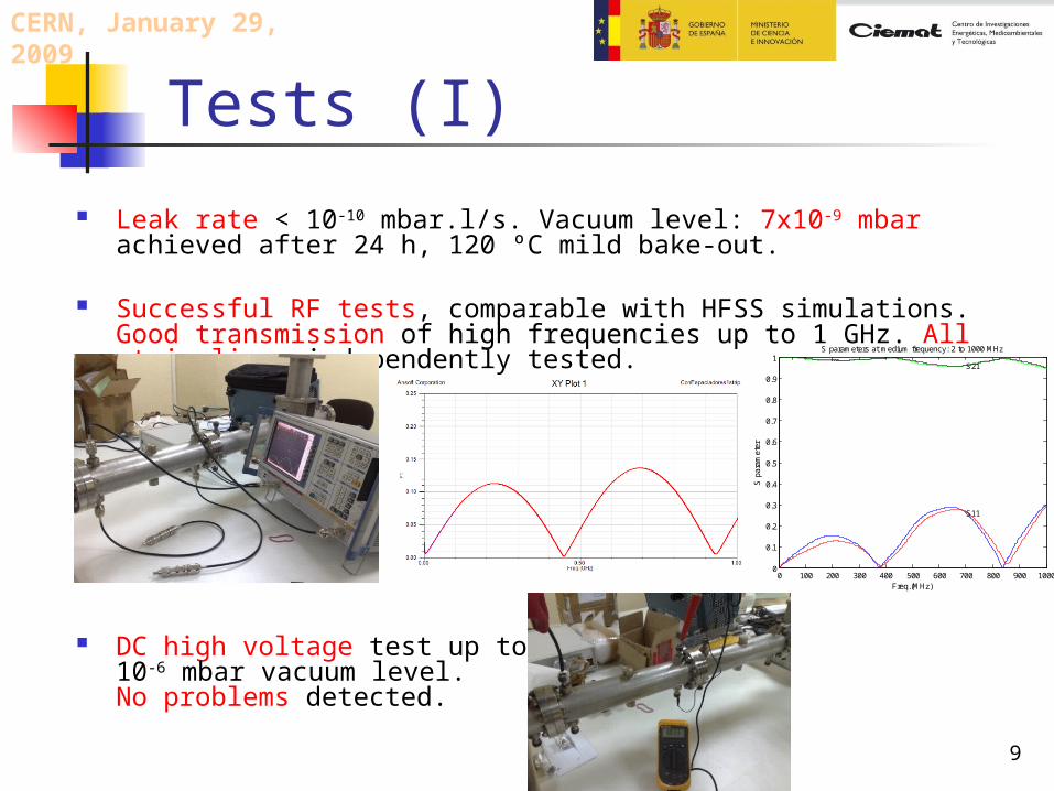
Leak rate < 10-10 mbar.l/s. Vacuum level: 7x10⁻⁹ mbar achieved after 24 h, 120 ºC mild bake-out.
Successful RF tests, comparable with HFSS simulations. Good transmission of high frequencies up to 1 GHz. All strip-lines independently tested.
DC high voltage test up to 3 kV in 10-6 mbar vacuum level. No problems detected.
CERN, January 29, 2009
Tests (I)
9
0 100 200 300 400 500 600 700 800 900 10000
0.1
0.2
0.3
0.4
0.5
0.6
0.7
0.8
0.9
1S parameters at medium frequency: 2 to 1000 MHz
Freq.(MHz)
S p
aram
eter
S11
S21

Pulser test. FID ±3.5 kV, 20 to 200 ns regulation, mirrored pulser.
Excellent transmission through the 4 Tail Clippers.
CERN, January 29, 2009
Tests (II)
10
-1 0 1 2 3 4 5
x 10-7
-4000
-3000
-2000
-1000
0
1000
2000
3000
4000Pulse response of Tail Clipper 2 using 20 ns pulse
Time (s)
Vol
tage
-50 0 50 100 150 200 250 300 350 400 4500
1000
2000
3000
400020 ns pulse directly to the load
Time (ns)
0 20 40 60 80 100 120 140 160 180 2000
100
200
300Pulse frequency content
Frequency (MHz)
-50 0 50 100 150 200 250 300 350 400 4500
1000
2000
3000
400020 ns pulse passing through Strip2 of TailClipper 2
Time (ns)
0 20 40 60 80 100 120 140 160 180 2000
100
200
300Pulse frequency content
Frequency (MHz)

Tail Clippers design and calculations were successfully developed according to the experience gained from the CTF3 kicker.
Manufacturing was a challenging process, especially for the electrical connection between feedthrough and electrodes.
Leak rate was successful. Final vacuum successfully achieved at CERN using mild bake-out.
RF, high voltage and pulsed test were successfully developed at CIEMAT.
The Tail Clippers were delivered to CERN on time and are being currently installed and tested.
Conclusions
CERN, January 29, 2009
11