Design, Manufacture and Installation of Theatrical Equipment...
18
Design, Manufacture and Installation of Theatrical Equipment Worldwide (315) 451-3440 Fax (315) 451-1766 www.jrclancy.com 003-854 rev 2: April, 2011 Design, Manufacture and Installation of Theatrical Equipment Worldwide Fire Curtain Hoist (Part No. 016-500P) Maintenance Manual IMPORTAT SAFETY IFORMATIO ............................................................................................................... 2 PRODUCT USE REQUIREMETS ......................................................................................................................... 3 MAITEACE SCHEDULE .................................................................................................................................. 3 REPLACEMET PARTS .......................................................................................................................................... 3 RECOMMEDED TOOLS ....................................................................................................................................... 4 ISPECTIO AD MAITEACE PROCEDURES ......................................................................................... 5 MACHINE COVERS ..................................................................................................................................................... 5 MOUNTING HARDWARE ............................................................................................................................................. 5 BLOCKS AND WIRE ROPE........................................................................................................................................... 5 CABLE KEEPERS ........................................................................................................................................................ 7 MOTOR AND GEAR REDUCER .................................................................................................................................... 8 CIRCUIT PROTECTION AND CONTROL ELECTRONICS .................................................................................................. 9 LIMIT SWITCH SETTINGS .......................................................................................................................................... 10 RELEASE MECHANISMS ........................................................................................................................................... 13 HYDRAULIC DAMPENER ......................................................................................................................................... 14 WARNING SIGNS AND OPERATIONAL INSTRUCTIONS ............................................................................................... 16 SERVICE LIGHT ........................................................................................................................................................ 16 DECOMMISSIOIG AD DISPOSAL ............................................................................................................... 16 HOW TO COTACT JR CLACY........................................................................................................................ 16 MAITEACE AD ISPECTIO LOG .......................................................................................................... 17
Transcript of Design, Manufacture and Installation of Theatrical Equipment...

Design, Manufacture and Installation of Theatrical Equipment Worldwide
(315) 451-3440 ���� Fax (315) 451-1766 ���� www.jrclancy.com
003-854 rev 2: April, 2011
Design, Manufacture and Installation of Theatrical Equipment Worldwide
Fire Curtain Hoist (Part No. 016-500P)
Maintenance Manual IMPORTAT SAFETY IFORMATIO ............................................................................................................... 2
PRODUCT USE REQUIREMETS ......................................................................................................................... 3
MAITEACE SCHEDULE .................................................................................................................................. 3
REPLACEMET PARTS .......................................................................................................................................... 3
RECOMMEDED TOOLS ....................................................................................................................................... 4
ISPECTIO AD MAITEACE PROCEDURES ......................................................................................... 5
MACHINE COVERS ..................................................................................................................................................... 5
MOUNTING HARDWARE ............................................................................................................................................. 5
BLOCKS AND WIRE ROPE ........................................................................................................................................... 5
CABLE KEEPERS ........................................................................................................................................................ 7
MOTOR AND GEAR REDUCER .................................................................................................................................... 8
CIRCUIT PROTECTION AND CONTROL ELECTRONICS .................................................................................................. 9
LIMIT SWITCH SETTINGS .......................................................................................................................................... 10
RELEASE MECHANISMS ........................................................................................................................................... 13
HYDRAULIC DAMPENER ......................................................................................................................................... 14
WARNING SIGNS AND OPERATIONAL INSTRUCTIONS ............................................................................................... 16
SERVICE LIGHT ........................................................................................................................................................ 16
DECOMMISSIOIG AD DISPOSAL ............................................................................................................... 16
HOW TO COTACT JR CLACY ........................................................................................................................ 16
MAITEACE AD ISPECTIO LOG .......................................................................................................... 17

Fire Curtain Hoist Maintenance Manual Page 2
Design, Manufacture and Installation of Theatrical Equipment Worldwide
(315) 451-3440 ���� Fax (315) 451-1766 ���� www.jrclancy.com
003-854 rev 2: April, 2011
IMPORTANT SAFETY INFORMATION
• The procedures in this manual are for use by qualified personnel only. If you are not qualified, contact the company that installed your system or the JR Clancy factory to find the nearest service provider.
• The Fire Curtain System Inspection Checklist must be completely filled out and a copy returned to JR Clancy as proof of initial and subsequent annual inspections. Proof of inspection may be required to activate and maintain the warranty period for this product.
• A Hoist Information Label is attached to the front of the machine enclosure and it contains important speed and capacity information that is necessary for proper maintenance and use.
• All users must be aware of maintenance requirements and warned of the associated hazards. Keep a copy of this manual available along with all other product documentation for future reference.
WARNING! Improper installation or maintenance can cause the
machine to fail.
• Hoisting machines impose significant loads onto the structure to which they are attached. You are responsible to verify that an engineer or other qualified person has determined that this structure can withstand the loads.
• Equipment must be installed and maintained by qualified personnel.
• Annual inspection and maintenance of this product is required as a minimum. Some applications may require more frequent inspection and service.
• Do not substitute or modify components provided with this equipment.
• Do not exceed the 1100 lb (500 kg) recommended working load of the hoist.
• Do not lift or support people or animals.
DANGER! Electrocution Hazard
• Remove power before opening electrical panels or machine covers.
• Electrical equipment must be serviced by qualified electricians.
WARNING! Moving parts can cut or crush
• Keep body parts away from machinery in motion.
• Remove power source before working on machinery.
• Install all guards and covers after inspection and/or maintenance of the machine.

Fire Curtain Hoist Maintenance Manual Page 3
Design, Manufacture and Installation of Theatrical Equipment Worldwide
(315) 451-3440 ���� Fax (315) 451-1766 ���� www.jrclancy.com
003-854 rev 2: April, 2011
PRODUCT USE REQUIREMENTS
• Installation of this equipment must comply with local building codes.
• Equipment must be installed according to manufacturer’s drawings.
• Fire curtain hoists must be inspected by qualified personnel every year, or more frequently depending on use and local, state, and federal laws. They also feature circuit breakers located within the controls enclosure. Do not inhibit access to the machinery or controls in any way.
• Fire curtain hoists are designed for indoor use only in buildings with temperatures between 50º and 100º F (10º- 38ºC). Do not expose machines to rain or condensing moisture.
• The recommended working load and duty cycle of each machine is marked on the product data label on the machine. Do not exceed.
• The hoist machinery must be protected from oil, dust and other contaminants.
• The fire curtain hoist is approximately 25 inches (64 cm) wide, 16 inches (41 cm) deep, 54 inches (137 cm) tall and weighs approximately 550 lbs (250 Kg).
• The fire curtain should be closed at all times when the stage is not in use. Refer to national, state, and local codes for more information.
MAINTENANCE SCHEDULE
NOTICE: This machinery must be inspected and maintained annually by qualified personnel. Proof
of inspection is required to maintain warranty status.
Annual inspection and operator training is required to maintain the warranty period specified in your
information binder, and proof of annual inspection and training will be required to obtain warranty service.
Certain applications may demand more frequent inspections and maintenance. It is the responsibility of
the user to monitor the machinery and adjust the maintenance schedule accordingly. Be aware of
government regulations concerning the inspection of hoisting equipment.
REPLACEMENT PARTS
Lubricants and other components that can be procured locally are fully specified in the appropriate section
of this manual. Use only the specified type and grade of materials. Contact your local JR Clancy dealer to
obtain any parts not listed in this document.

Fire Curtain Hoist Maintenance Manual Page 4
Design, Manufacture and Installation of Theatrical Equipment Worldwide
(315) 451-3440 ���� Fax (315) 451-1766 ���� www.jrclancy.com
003-854 rev 2: April, 2011
RECOMMENDED TOOLS The following tools and materials may be used in this manual and during annual inspections and regular maintenance. This list is not exhaustive, but can be used as a starting point for selecting the proper tools. Personal Protective Equipment Small flat head screw driver (for adjusting limit switch) 3/8” Socket Wrench or Hex Nutdriver (to remove covers) 9/16” Open-Ended Box Wrench (to adjust dampener and/or limit switch) Wire Rope Termination Tools, as necessary 5/32” Hex (Allen) Key

Fire Curtain Hoist Maintenance Manual Page 5
Design, Manufacture and Installation of Theatrical Equipment Worldwide
(315) 451-3440 ���� Fax (315) 451-1766 ���� www.jrclancy.com
003-854 rev 2: April, 2011
INSPECTION AND MAINTENANCE PROCEDURES
MACHINE COVERS
1. Machines that have moving parts within reach of people must be fitted with covers during normal
operation. The fire curtain hoist is manufactured with a steel enclosure. Make sure all sections of
the enclosure are present. If all sections cannot be located, call the JR Clancy factory for
replacement parts.
2. Make sure that all fasteners are present and secured once covers are in place.
MOUNTING HARDWARE
WARNING! Improper mounting hardware or installation can cause the load to fall.
Mounting structure and hardware must be designed to support loads imposed by hoist.
1. The fire curtain hoist is designed to be anchored to the floor or the wall, depending on the
installation. See the job drawings for specific mounting notes for each installation. Verify all anchors
are in place and are fully tightened.
BLOCKS AND WIRE ROPE
1. Check the fleet angle on all sheaves and adjust to keep within 1.5 degrees. This is equivalent to 3”
(76 mm) over 10 ft (3 m).
2. Remove the cover from the machine and observe the machine while running. Listen for the sound
of cables that might be rubbing against the machine or improperly aligned.
3. Test the operation of the machine. Cables entering the drum should not rub on the drum wraps or
skip drum grooves.
4. Make sure the wire rope is free of kinks, distortions and broken wires. The wire rope specification is
listed on the fire curtain hoist product label. If the condition of the wire rope is satisfactory, proceed
to Step 6.
WARNING! Do not use wire ropes of different dimensional or structural characteristics.
5. If replacement of the cable is necessary, follow the procedure below:
5.1 Move the load to a location where it can be secured to the building structure. Typically, the fire curtain can be lowered so its weight is resting on the safety chains.
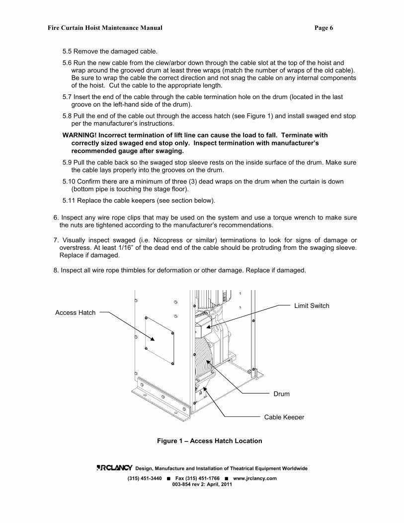
5.2 Rotate the drum so that the cable termination hole is visible through the access hatch on the left side of the machine (see Figure 1).
WARNING! Disconnect the power before working on the machinery.
5.3 Remove the cable keepers by pulling the bracket gently forward (against the tension of the spring) until the bottom of the bracket slides out of the bottom plate of the enclosure. Put the cable keepers aside until installation of the new cable is complete.
WARNING! Do not disconnect wire rope until load is secured and line is slack.
5.4 Secure the load being held by the hoist and take note of how many wraps are on the drum.
Fire Curtain Hoist Maintenance Manual Page 6
Design, Manufacture and Installation of Theatrical Equipment Worldwide
(315) 451-3440 ���� Fax (315) 451-1766 ���� www.jrclancy.com
003-854 rev 2: April, 2011
5.5 Remove the damaged cable.
5.6 Run the new cable from the clew/arbor down through the cable slot at the top of the hoist and wrap around the grooved drum at least three wraps (match the number of wraps of the old cable). Be sure to wrap the cable the correct direction and not snag the cable on any internal components of the hoist. Cut the cable to the appropriate length.
5.7 Insert the end of the cable through the cable termination hole on the drum (located in the last groove on the left-hand side of the drum).
5.8 Pull the end of the cable out through the access hatch (see Figure 1) and install swaged end stop per the manufacturer’s instructions.
WARNING! Incorrect termination of lift line can cause the load to fall. Terminate with
correctly sized swaged end stop only. Inspect termination with manufacturer’s
recommended gauge after swaging.
5.9 Pull the cable back so the swaged stop sleeve rests on the inside surface of the drum. Make sure the cable lays properly into the grooves on the drum.
5.10 Confirm there are a minimum of three (3) dead wraps on the drum when the curtain is down (bottom pipe is touching the stage floor).
5.11 Replace the cable keepers (see section below).
6. Inspect any wire rope clips that may be used on the system and use a torque wrench to make sure the nuts are tightened according to the manufacturer’s recommendations.
7. Visually inspect swaged (i.e. Nicopress or similar) terminations to look for signs of damage or overstress. At least 1/16” of the dead end of the cable should be protruding from the swaging sleeve. Replace if damaged.
8. Inspect all wire rope thimbles for deformation or other damage. Replace if damaged.
Figure 1 – Access Hatch Location
Drum
Access Hatch
Cable Keeper
Limit Switch

Fire Curtain Hoist Maintenance Manual Page 7
Design, Manufacture and Installation of Theatrical Equipment Worldwide
(315) 451-3440 ���� Fax (315) 451-1766 ���� www.jrclancy.com
003-854 rev 2: April, 2011
CABLE KEEPERS
WARNING! Improperly installed or missing cable keepers can cause the lift line to come off
the drum and the load to fall. Do not operate hoist with cable keepers removed.
1. Check the distance between the wire rope wrapped on the drum and the UHMW keeper (see Figures 2 and 3). The distance should be 1/32” to 1/16” (1mm to 2mm). 2. Check the spring between the two cable keeper brackets to make sure it is seated properly and holding the keepers against the surface of the drum.
3. Check that the bottom of the each bracket is seated in the slots in bottom plate of the enclosure. 4. Check all bolts in the cable keeper assemblies are tight. 5. Observe the surface of the keepers to look for abrasion or other damage. 6. Observe the machine while operating and make sure the cable keepers are properly positioned and are not rubbing on the cable.
Figure 2 - Side View of Cable Drum (Enclosure Removed for Clarity)
Figure 3 – Cable Keeper Alignment
Cable Keeper
Drum
Wire Rope (Lift Line)
Limit Switch
Swaged End Stop Spring
Gearbox
Cable Keeper
Smooth Race
Observe for Abrasion

Fire Curtain Hoist Maintenance Manual Page 8
Design, Manufacture and Installation of Theatrical Equipment Worldwide
(315) 451-3440 ���� Fax (315) 451-1766 ���� www.jrclancy.com
003-854 rev 2: April, 2011
MOTOR AND GEAR REDUCER
NOTICE: At least 30 lbs of tension on the fire curtain release line is required to secure the motor
brake during normal operation. Do not operate hoist with release line improperly tensioned.
1. With the fire line tight (not activated), observe the machinery while raising and lowering the load
using the control panel. The brake on the electric motor should engage and stop the load. The load
should stop quickly and without any back-winding. If the load backwinds the electric motor brake
should be serviced. Contact the JR Clancy factory.
2. Check the gear reducer oil level by removing the access panel on the lower left side of the machine.
The oil level should be visible through the fill hole as shown. (See Figure 3). The gear reducer oil
must be replaced every two years, or analyzed annually by a commercial laboratory to ensure that
the oil properties and contamination levels are acceptable. Any oil added to the reducer must match
the manufacturer and type marked on the reducer label that is fastened directly to the gear case.
Note that bearings inside the electric motor are lifetime lubricated and sealed and do not require
periodic lubrication.
Figure 4 – Gear Reducer Lubrication Ports
3. Inspect for any loose fasteners and retighten as necessary.
4. Check the reducer breather valve and make sure that the protective rubber band is removed and
discarded. See Figure 5.
Figure 5 – Reducer breather valve with protective band
FILL LEVEL
VENT
DRAIN
Brass breather valve Rubber protective band Remove after installation

Fire Curtain Hoist Maintenance Manual Page 9
Design, Manufacture and Installation of Theatrical Equipment Worldwide
(315) 451-3440 ���� Fax (315) 451-1766 ���� www.jrclancy.com
003-854 rev 2: April, 2011
CIRCUIT PROTECTION AND CONTROL ELECTRONICS
The hoist is controlled through the use of a self-protected motor starter inside the controls enclosure. See Figure 6. This unit includes both overload sensors and a disconnect switch to shut off the motor power. The disconnect handle is turned to the “twelve o’clock” position to turn the power on, and to “nine o’clock” to turn the power off. This handle also functions as a fault indicator; when the sensors detect an overload, the power will automatically be disconnected and the handle will snap to the “ten-thirty” position. To reset a fault turn the disconnect handle to the “reset” position (seven o’clock) and then back to the “on” position. The dial of the overload sensor is set at the factory to match the motor’s Full Load Amperage (FLA). Do not adjust this setting unless directed by a JR Clancy factory representative. For all other adjustments to the control electronics contact the JR Clancy factory.
Figure 6 – Fixed Speed Starter Module
DANGER! Electrocution hazard. Remove power source before opening electrical
enclosures.

Fire Curtain Hoist Maintenance Manual Page 10
Design, Manufacture and Installation of Theatrical Equipment Worldwide
(315) 451-3440 ���� Fax (315) 451-1766 ���� www.jrclancy.com
003-854 rev 2: April, 2011
LIMIT SWITCH SETTINGS
WARNING! Machinery and loads can collide with surroundings if limit switches are
incorrectly adjusted. Operator or observer must be in sight of all obstacles in the path of
machine or load. Do not operate over the heads of people.
Run the fire curtain hoist to its upper and lower limits. The upper limit should stop the load no closer than 6 inches (150 mm) from the nearest obstruction above the curtain. The lower limit should be set just past the point where the curtain touches the floor. The total possible travel of the hoist is printed on the identification label on the front of the hoist, and must not be exceeded. At all times, there should be three dead wraps when the drum is empty and no less than one empty groove when the drum is full.
The fire curtain hoist is provided with two types of travel limits: operational limits and overtravel limits.
1. Operational (normal) limits control the distance the load will travel (both up and down) under normal
conditions, such as the normal low and high trim (positions) of a load. These should be set within the
limits established by the overtravel limit switches.
2. Overtravel limits are intended to protect the building and equipment against damage from excessive
travel of the hoist system. These limits are often called the “ultimate” limits. Overtravel limits are
usually set within a few inches past the operational limits. These and other safety devices are set at
installation and should be tested occasionally, but never changed to suit temporary needs.
3. Before setting the limit switches, check the tension in the chain connecting the limit switch sprocket to
the drum. The chain should deflect a maximum of 3/4” under light hand pressure. The limit switch
sprocket should not be able to turn on its own.
NOTICE: Do not over-tension the chain. This will put excessive stress on the limit switch shaft.
3.1 If the chain requires adjustment, loosen the bolts that secure the limit switch mounting bracket to
the hoist enclosure, and slide the limit switch assembly up or down as necessary. Re-tighten the
bolts after adjustment.
Figure 7 – Rotary Limit Switch
WARNING! Striking an overtravel limit indicates that the primary operational limit has
failed. The system must be inspected and repaired if necessary. Contact the factory if
assistance is required.
Cam Stack
Limit Switches

Fire Curtain Hoist Maintenance Manual Page 11
Design, Manufacture and Installation of Theatrical Equipment Worldwide
(315) 451-3440 ���� Fax (315) 451-1766 ���� www.jrclancy.com
003-854 rev 2: April, 2011
NOTICE: The hoist cannot be operated if an overtravel limit has been activated. If this occurs, the
overtravel bypass switch located in the motor starter cabinet must be pressed to drive the hoist off of the
overtravel limit. If the limit switches require adjustment, follow the procedure below.
4. Determine the travel of the hoist:
4.1 Determine where the load must stop to avoid damage to the equipment or building, set overtravel limits short of this point. (For most fire curtains, the down overtravel limit will be set just past the point where the curtains weight is transferred to the safety chains)
4.2 Determine the range of travel required for the load, set the operational limits to stop at these points.
4.3 For each end of travel, set overtravel limit first, then set operational limits.
4.4 Make sure the operator or an observer can see the load for its entire travel.
5. Run the hoist in each direction. If limits are set properly, the hoist will stop automatically when the ends of travel are reached. If the limits need to be adjusted, follow steps below.
6. Establish switch rotation:
6.1 Remove hoist and limit switch covers.
6.2 Drive hoist in UP direction. Note direction of cam stack rotation.
6.3 Mark switch cover or label inside switch to record cam stack rotation.
7. Adjust limit.
7.1 Position operator or an observer so all parts of the lifted load can be seen.
7.2 Drive hoist to the desired end of travel.
7.3 Re-verify cam stack rotation (when the winch travels up, does the cam stack rotate clockwise or counterclockwise). Determine which side of the desired switch the limit cam must strike (i.e. if the cam stack rotates clockwise when the winch travels down, and you are setting a down limit, the cam must actuate the down limit while moving in a clockwise direction).
7.4 Loosen the central cam stack clamping screw 1/2 turn (Figure 8).
7.5 Locate the adjusting screw for the desired limit by referring to the numbers adjacent to the
adjusting screws. Note that the lowest switch in the cam stack (down overtravel) is switch 1, the
next switch (down limit) is switch 2, the next switch (up limit) is switch 3, and the highest switch
in the stack (up overtravel) is switch 4.
7.6 Rotate the adjusting screw to adjust the limit cam lobe to a position where the selected limit switch is just actuated (audible click).
7.7 Once the limit cam is at the proper place, tighten the cam stack clamping screw.

Fire Curtain Hoist Maintenance Manual Page 12
Design, Manufacture and Installation of Theatrical Equipment Worldwide
(315) 451-3440 ���� Fax (315) 451-1766 ���� www.jrclancy.com
003-854 rev 2: April, 2011
Figure 8 – Rotary Limit Switch Cam Stack
8. Test Limit
8.1 Drive winch away from limit until limit is cleared (use overtravel bypass switch to move off overtravel limit).
8.2 Drive winch toward limit until limit stops motion.
8.3 Assess stopping position (measurement vs. target).
8.4 Drive winch off limit (use overtravel bypass switch to move winch off overtravel limit).
9. Refine Limit Adjustment
9.1 Repeat the Adjust Limit procedure, as detailed above.
9.2 Move cam lobe closer to switch to make switch trip sooner (decrease travel distance).
9.3 Move cam lobe further from switch to make switch trip later (increase travel distance).
9.4 Make sure to tighten cam stack clamping screw after each adjustment!
9.5 Retest limit adjustment until winch stops at desired position.
10. Adjust Remaining Limits
10.1 Once overtravel limit is set, set normal limit at same end of travel.
10.2 Check to ensure that there is sufficient distance between normal limit and overtravel limit - if the winch strikes both limits before stopping, increase the distance between the limits by moving the normal limit to stop the load sooner.
10.3 Once all limits are set, check that cam stack clamping screw is tightened, then replace the limit switch cover.

Fire Curtain Hoist Maintenance Manual Page 13
Design, Manufacture and Installation of Theatrical Equipment Worldwide
(315) 451-3440 ���� Fax (315) 451-1766 ���� www.jrclancy.com
003-854 rev 2: April, 2011
RELEASE MECHANISMS
The fire curtain hoist is rigged to a number of release mechanisms around the proscenium opening
designed to release the curtain to lower automatically in case of fire. These can include manual release
levers, fusible links, electro-thermal links and the SureGuard II electro-mechanical release. These
devices are connected together and to the hoist with the fire line (typically 1/8” galvanized utility cable).
When tension in the fire line is released, the brake on the gearmotor is disengaged allowing the curtain to
fall. The fire line should be inspected and tested at least every 90 days.
1. Inspect the fire line. The line should be free to fall slack if any of the release mechanisms are
tripped. Replace any damaged components and clear any obstructions.
WARNING! Releasing the fire curtain to test emergency descent will allow the curtain to fall at
a high rate of speed. Make sure the path of the curtain is free of obstructions and personnel
before testing.
2. Make sure the proscenium opening is clear then manually trigger one of the release mechanisms
to test the operation of the curtain. Take note of the time required for the curtain to reach the floor
to see if adjustment of the hydraulic dampener is required (see next section).
WARNING! Failure to reset release line properly after an emergency descent (or test) and
before raising curtain will cause curtain to close when “UP” button is released. Keep clear of
curtain when raising or lowering.
3. After curtain falls, reset the fire line and make sure the line has at least 30 lbs of tension.
4. Use the hoist controls to raise the curtain to its high trim. (Note: Raising the curtain may require
using the overtravel bypass switch in the controls enclosure if the overtravel limit switch was
activated when the curtain closed.)
Fire Curtain Hoist Maintenance Manual Page 14
Design, Manufacture and Installation of Theatrical Equipment Worldwide
(315) 451-3440 ���� Fax (315) 451-1766 ���� www.jrclancy.com
003-854 rev 2: April, 2011
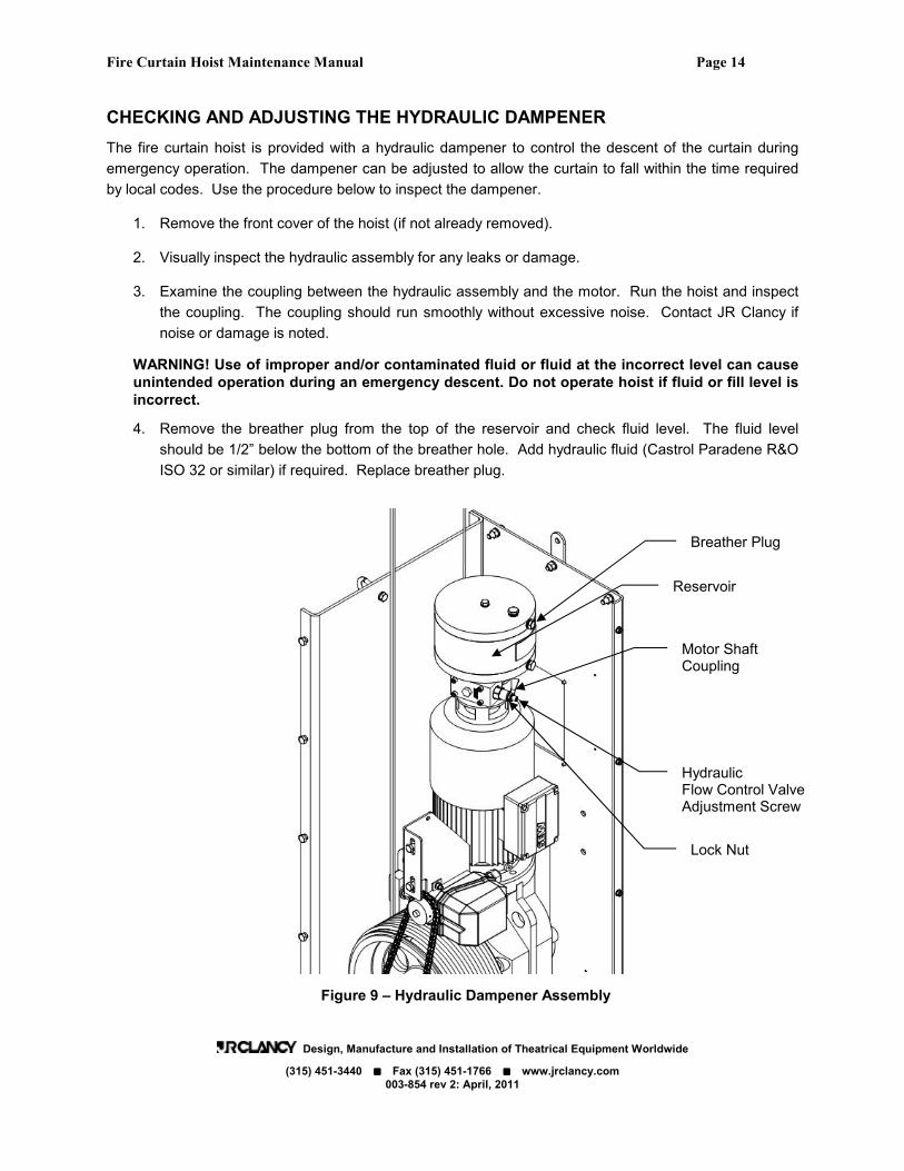
CHECKING AND ADJUSTING THE HYDRAULIC DAMPENER
The fire curtain hoist is provided with a hydraulic dampener to control the descent of the curtain during
emergency operation. The dampener can be adjusted to allow the curtain to fall within the time required
by local codes. Use the procedure below to inspect the dampener.
1. Remove the front cover of the hoist (if not already removed).
2. Visually inspect the hydraulic assembly for any leaks or damage.
3. Examine the coupling between the hydraulic assembly and the motor. Run the hoist and inspect
the coupling. The coupling should run smoothly without excessive noise. Contact JR Clancy if
noise or damage is noted.
WARNING! Use of improper and/or contaminated fluid or fluid at the incorrect level can cause
unintended operation during an emergency descent. Do not operate hoist if fluid or fill level is
incorrect.
4. Remove the breather plug from the top of the reservoir and check fluid level. The fluid level
should be 1/2” below the bottom of the breather hole. Add hydraulic fluid (Castrol Paradene R&O
ISO 32 or similar) if required. Replace breather plug.
Figure 9 – Hydraulic Dampener Assembly
Lock Nut
Hydraulic Flow Control Valve Adjustment Screw
Reservoir
Breather Plug
Motor Shaft Coupling

Fire Curtain Hoist Maintenance Manual Page 15
Design, Manufacture and Installation of Theatrical Equipment Worldwide
(315) 451-3440 ���� Fax (315) 451-1766 ���� www.jrclancy.com
003-854 rev 2: April, 2011
Typically, the curtain is required to close within 30 seconds and must take at least 5 seconds to close the
last 8 feet. (Note: These requirements may vary depending on local codes and regulations.) If the curtain
does not complete its travel in the required time, follow the instructions below to adjust the dampener.
1. Determine the required closing times per local codes.
2. Lift the curtain to the raised position. Release the curtain using one of the manual release levers
at each side of the stage or the test button on the SureGuard II electro-mechanical release. Time
the descent of the curtain. If the curtain does not fall within the required time, or the curtain
bounces at the bottom of travel after hitting the stage, adjust the valve using the steps below.
WARNING! Improper adjustment of the hydraulic dampener can cause the curtain to fall too
fast in an emergency descent, resulting in damage and/or personal injury. Use caution when
adjusting hydraulic dampener. Keep area under curtain clear of obstructions and personnel.
3. Remove the front cover of the hoist. Locate the hydraulic flow control valve (Figure 9).
4. Loosen the lock nut on the adjustment screw and adjust the valve. Turning the valve adjustment
screw clockwise will decrease the speed of the curtain, turning counterclockwise will increase the
speed of the curtain. After adjusting, tighten the lock nut.
5. Retime the descent of the curtain. (Note: Raising the curtain may require using the overtravel
bypass switch in the controls enclosure if the overtravel limit switch was activated when the
curtain closed.) If necessary, repeat adjustment until descent time is correct.
6. Replace cover on hoist.
7. Check and reset fire line if needed.
8. If multiple tests were required to set the hydraulic dampener, wait 30 minutes for the hydraulic
fluid to return ambient temperature, and then repeat the test a final time to confirm that the
descent is still within the required time.

Fire Curtain Hoist Maintenance Manual Page 16
Design, Manufacture and Installation of Theatrical Equipment Worldwide
(315) 451-3440 ���� Fax (315) 451-1766 ���� www.jrclancy.com
003-854 rev 2: April, 2011
WARNING SIGNS AND OPERATIONAL INSTRUCTIONS
In the event that operation, service, or training questions arise, the users must have contact information
for qualified service personnel readily available.
1. Make sure that the JR Clancy motorized rigging safety sign is placed in a prominent location and that
the service contact information is filled in.
2. Interview the user and make sure that they have access to the Operations Manual. Also, a service
log form was provided to the owner at the time this machinery was commissioned. Locate this log
and examine it. The following information should be recorded for each occasion of service:
• Date of service
• The provider of the service, with contact information.
• The machinery, i.e channel number, on which the service was performed.
• The work that was performed.
NOTICE: Documentation of annual inspection is required to maintain the full warranty period of
the hoist and may need to be provided upon request to obtain warranty service.
SERVICE LIGHT A service indicator light has been provided on the equipment to remind the users of the annual inspection and service requirement. Contact the JR Clancy factory or an authorized dealer if the service light is on. After service is complete the light timer must be reset by an authorized JR Clancy dealer.
DECOMMISIONING AND DISPOSAL
Remove machines if necessary using qualified personnel and safe rigging practices. Any modifications to the structure and wiring must be performed by qualified persons and conform to local codes. Do not defeat interlock switches or any other safety features of remaining machines or control system. Dispose of all materials according to local codes.
CONTACT JR CLANCY WITH QUESTIONS
Contact the factory at any time with questions and comments concerning this product:
JR Clancy Incorporated 7041 Interstate Island Road Syracuse, NY 13209 USA Telephone (315) 451-3440

Fire Curtain Hoist Maintenance Manual Page 17
Design, Manufacture and Installation of Theatrical Equipment Worldwide
(315) 451-3440 ���� Fax (315) 451-1766 ���� www.jrclancy.com
003-854 rev 2: April, 2011
MAINTENANCE AND INSPECTION LOG
Use this log to keep track of required annual inspections and any service performed on your motorized rigging equipment. Keep this in a binder along with other service information such as inspection reports.
DATE SERVICE PERFORMED SERVICE PROVIDER INITIALS

Fire Curtain Hoist Maintenance Manual Page 18
Design, Manufacture and Installation of Theatrical Equipment Worldwide
(315) 451-3440 ���� Fax (315) 451-1766 ���� www.jrclancy.com
003-854 rev 2: April, 2011
Attach Additional Pages As Necessary.