DESIGN MANUAL FOR STRUCTURAL STAINLESS … · P i ii i i any i i ii i ii i i i i i i i i i ii...
116
DESIGN MANUAL FOR STRUCTURAL STAINLESS STEEL 4 TH EDITION – COMMENTARY
Transcript of DESIGN MANUAL FOR STRUCTURAL STAINLESS … · P i ii i i any i i ii i ii i i i i i i i i i ii...

DESIGN MANUAL FOR STRUCTURAL STAINLESS STEEL4TH EDITION – COMMENTARY

i
SCI PUBLICATION P421
DESIGN MANUAL FOR STRUCTURAL STAINLESS STEEL4TH EDITION – COMMENTARY
ii
© 2018 SCI. All rights reserved.
Publication Number: SCI P421
Published by:SCI, Silwood Park, Ascot, Berkshire. SL5 7QN UK
T: +44 (0)1344 636525 F: +44 (0)1344 636570 E: reception@steel‑sci.com
www.steel‑sci.com
To report any errors, contact: publications@steel‑sci.com
Apart from any fair dealing for the purposes of research or private study or criticism or review, as permitted under the Copyright Designs and Patents Act, 1988, this publication may not be reproduced, stored or transmitted, in any form or by any means, without the prior permission in writing of the publishers, or in the case of reprographic reproduction only in accordance with the terms of the licences issued by the UK Copyright Licensing Agency, or in accordance with the terms of licences issued by the appropriate Reproduction Rights Organisation outside the UK.
Enquiries concerning reproduction outside the terms stated here should be sent to the publishers, SCI.
Although care has been taken to ensure, to the best of our knowledge, that all data and information contained herein are accurate to the extent that they relate to either matters of fact or accepted practice or matters of opinion at the time of publication, SCI, the authors and the reviewers assume no responsibility for any errors in or misinterpretations of such data and/or information or any loss or damage arising from or related to their use.
Publications supplied to the members of the Institute at a discount are not for resale by them.
British Library Cataloguing‑in‑Publication Data. A catalogue record for this book is available from the British Library.
SCI (The Steel Construction Institute) is the leading, independent provider of technical expertise and disseminator of best practice to the steel construction sector. We work in partnership with clients, members and industry peers to help build businesses and provide competitive advantage through the commercial application of our knowledge. We are committed to offering and promoting sustainable and environmentally responsible solutions.
Our service spans the following areas:MembershipIndividual & corporate membership
AdviceMembers advisory service
InformationPublicationsEducationEvents & training
ConsultancyDevelopmentProduct developmentEngineering supportSustainability
AssessmentSCI Assessment
SpecificationWebsitesEngineering software
Front cover credits
Top left: Canopy, Napp Pharmaceutical, Cambridge, UK Grade 1.4401, Courtesy: m-tec
Bottom left: Dairy Plant at Cornell University, College of Agriculture and Life Sciences, Grade 1.4301/7, Courtesy: Stainless Structurals
Top right: Skid for offshore regasification plant, Grade 1.4301, Courtesy: Montanstahl
Bottom right: Águilas footbridge, Spain Grade 1.4462, Courtesy Acuamed

iii
Fourth Edition
This Fourth Edition of the Design Manual has been prepared by Nancy Baddoo of The Steel Construction Institute as part of the RFCS Project Promotion of new Eurocode rules for structural stainless steels (PUREST) (contract 709600).
It is a complete revision of the Third Edition; the major changes are as follows:
▪ Alignment with the 2015 amendment to EN 1993-1-4, ▪ Inclusion of ferritic stainless steels, based on the work of the Structural applications of ferritic stainless steels (SAFSS) project (RFSR-CT-2010-00026),
▪ New data on the thermal and mechanical properties of stainless steels in fire are added, ▪ The design data, design rules and references to current versions of European standards, including EN 10088, EN 1993 and EN 1090 are updated,
▪ Addition of an annex on material modelling, ▪ Addition of an annex which gives a method for calculating an enhanced strength arising from cold forming,
▪ Addition of an annex which gives less conservative design rules by exploiting the benefits of strain hardening through the use of the Continuous Strength Method.
The organisations who participated in the PUREST project were:
The Steel Construction Institute (SCI) (co-ordinator)Silwood Park, Ascot, SL5 7QN, United Kingdom www.steel-sci.com
Universitat Politècnica de Catalunya (UPC)Calle Jordi Girona 31, Barcelona 08034, Spain www.upc.edu
Universität Duisburg-Essen (UDE)Universitätsstraße 2, Essen 45141, Germanywww.uni-due.de
Katholieke Universiteit Leuven (KU Leuven)Oude Markt 13, Leuven 3000, Belgiumwww.kuleuven.be
RINA Consulting-Centro Sviluppo Materiali S.p.A. (CSM)Via Di Castel Romano 100, Rome 00128, Italywww.rinaconsulting.org/en/csm
Stalbyggnadinstitutet (SBI)Kungsträdgårdsgatan 10, 111 47 Stockholm, Swedenwww.sbi.se
Politechnika Rzeszowska im. Ignacego Lukasiewicza (PRz)al. Powstancow Warszawy 12, Rzeszów, 35 959, Polandwww.prz.edu.pl
Imperial College of Science Technology and MedicineSouth Kensington Campus Exhibition Road, London, SW7 2AZ, United Kingdomwww.imperial.ac.uk
Teräsrakenneyhdistys ryUnioninkatu 14 3 krs, Helsinki 00130, Finlandwww.terasrakenneyhdistys.fi
České vysoké učení technické v Praze (CVUT)Zikova 4, Praha 16636, Czech Republicwww.cvut.cz
Universidade de CoimbraPaço das Escolas, Coimbra, 3001 451, Portugalwww.uc.pt
OneSource Consultoria InformáticaUrbanizaçao Ferreira Jorge - 1° dto Lote 14, Coimbra 3040 016 , Portugalwww.onesource.pt
PREFACE

iv
Preface
The following people made a valuable contribution to the preparation of this Fourth Edition:
▪ Sheida Afshan (Brunel University London, UK) ▪ Itsaso Arrayago (Universitat Politècnica de Catalunya, Spain) ▪ Leroy Gardner (Imperial College London, UK) ▪ Graham Gedge (Arup, UK) ▪ Michal Jandera (Czech Technical University of Prague, Czech Republic) ▪ Esther Real (Universitat Politècnica de Catalunya, Spain) ▪ Barbara Rossi (KU Leuven, Belgium) ▪ Natalie Stranghöner (Universität Duisberg-Essen, Germany) ▪ Ou Zhao (Nanyang Technological University, Singapore)
The Commentary to this Fourth Edition was updated by Professor Leroy Gardner of Imperial College London, assisted by Miss Fiona Walport, Dr Ou Zhao, Dr Craig Buchanan and Dr Sheida Afshan.
ACKNOWLEDGEMENTSThe following organisations provided financial support for this edition of the Design Manual and their assistance is gratefully acknowledged:
▪ The European Union’s Research Fund for Coal and Steel, ▪ Outokumpu, ▪ Aperam, ▪ Industeel, ▪ Acerinox, ▪ Companhia Brasileira de Metalurgia e Mineração (CBMM), ▪ Nickel Institute, ▪ Stalatube.
v
This Design Manual has been prepared for the guidance of engineers experienced in the design of carbon steel structural steelwork though not necessarily in stainless steel structures. It is not in any way intended to have a legal status or absolve the engineer of responsibility to ensure that a safe and functional structure results.
The Manual is divided into two parts:
▪ Part I - Recommendations▪ Part II - Design Examples
The Recommendations in Part I are formulated in terms of limit state philosophy and, in general, are in compliance with the current versions of the following Parts of Eurocode 3 Design of steel structures:
EN 1993-1-1 Design of steel structures: General rules and rules for buildingsEN 1993-1-2 Design of steel structures: Structural fire designEN 1993-1-3 Design of steel structures: General rules: Supplementary rules for
cold-formed members and sheetingEN 1993-1-4 Design of steel structures: General rules: Supplementary rules for
stainless steelsEN 1993-1-5 Design of steel structures: Plated structural elementsEN 1993-1-8 Design of steel structures: Design of jointsEN 1993-1-9 Design of steel structures: FatigueEN 1993-1-10 Design of steel structures: Material toughness and
through-thickness properties
Eurocode 3 is currently under revision and a new version of each part, including EN 1993-1-4, is due for publication in about 2023. In certain instances, the Design Manual gives the new rules or design data which are likely to be included in this next edition of EN 1993-1-4. A shaded box explains the difference between these new rules and those rules currently in EN 1993-1-4:2015.
This Design Manual gives recommended values for certain factors. These values may be subject to modification at a national level by the National Annexes.
FOREWORD
vi
foreword
The Design Examples contained in Part II demonstrate the use of the recommendations. A cross-reference system locates that section of the examples corresponding to a particular recommendation.
The Recommendations and Design Examples are available online at www.steel-stainless.org/designmanual and at Steelbiz, the SCI technical information system (www.steelbiz.org). A Commentary to the Recommendations, which includes a full set of references, is also available online at these web sites. The purpose of the Commentary is to allow the designer to assess the basis of the recommendations and to facilitate the development of revisions as and when new data become available. Opportunity is taken to present the results of various test programmes conducted specifically to provide background data for the Design Manual.
Online design software and apps for mobile devices are also available from www.steel-stainless.org/designmanual which calculate section properties and member resistances for standard section sizes or user defined sections in accordance with the Recommendations in this Design Manual.
The design recommendations presented in this document are based upon the best knowledge available at the time of publication. However, no responsibility of any kind for injury, death, loss, damage or delay, however caused, resulting from the use of the recommendations can be accepted by the project partners or others associated with its preparation.
vii
Contents
Page No.
C.1 INTRODUCTION 1 C.1.1 What is stainless steel? 1 C.1.2 Suitable stainless steels for structural applications 1 C.1.3 Applications of stainless steels in the construction industry 2 C.1.4 Scope of this Design Manual 2 C.1.5 Symbols 3 C.1.6 Conventions for member axes 3
C.2 PROPERTIES OF STAINLESS STEELS 4 C.2.1 Basic stress-strain behaviour 4 C.2.2 Factors affecting stress-strain behaviour 4 C.2.3 Relevant standards and design strengths 9 C.2.4 Physical properties 10 C.2.5 Effects of temperature 10 C.2.6 Galvanizing and contact with molten zinc 10 C.2.7 Availability of product forms 10 C.2.8 Life cycle costing and environmental impact 13
C.3 DURABILITY AND SELECTION OF MATERIALS 14 C.3.1 Introduction 14 C.3.2 Types of corrosion 14 C.3.3 Corrosion in selected environments 15 C.3.4 Design for corrosion control 15 C.3.5 Selection of materials 16
C.4 BASIS OF DESIGN 18 C.4.1 General requirements 18 C.4.2 Limit state design 18 C.4.3 Loading 18
C.5 CROSS-SECTION DESIGN 19 C.5.1 General 19 C.5.2 Maximum width-to-thickness ratios 19 C.5.3 Classification of cross-sections 20 C.5.4 Effective widths 26 C.5.5 Stiffened elements 27 C.5.6 Calculation of geometric section properties 27 C.5.7 Resistance of cross-sections 28
C.6 MEMBER DESIGN 29 C.6.1 Introduction 29 C.6.2 Tension members 31 C.6.3 Compression members 31 C.6.4 Flexural members 37 C.6.5 Members subject to combinations of axial loads and bending
moments 44
C.7 JOINT DESIGN 46 C.7.1 General recommendations 46 C.7.2 Bolted connections 46 C.7.3 Mechanical fasteners for thin gauge material 53
viii
C.7.4 Welded connections 53
C.8 FIRE RESISTANT DESIGN 55 C.8.1 General 55 C.8.2 Mechanical properties at elevated temperatures 55 C.8.3 Determination of structural fire resistance 56 C.8.4 Thermal properties at elevated temperatures 58 C.8.5 Material modelling at elevated temperatures 58
C.9 FATIGUE 60 C.9.1 Introduction 60 C.9.2 S-N data for stainless steels 60 C.9.3 S-N data for cold worked stainless steels 65 C.9.4 Fatigue crack growth data for stainless steels 65
C.10 TESTING 72
C.11 FABRICATION ASPECTS 73 C.11.1 Introduction 73 C.11.2 EN 1090 Execution of steel structures and aluminium structures 73C.11.3 Execution classes 73 C.11.4 Storage and handling 73 C.11.5 Shaping operations 73 C.11.6 Welding 73 C.11.7 Galling and seizure 74 C.11.8 Finishing 74
C.ANNEX A CORRELATION BETWEEN STAINLESS STEEL DESIGNATIONS 76
C.ANNEX B STRENGTH ENHANCEMENT OF COLD FORMED SECTIONS 77
C.ANNEX C MODELLING OF MATERIAL BEHAVIOUR 78
C.ANNEX D CONTINUOUS STRENGTH METHOD 80 C.D.1 General 80 C.D.2 Material modelling 80 C.D.3 Cross-section deformation capacity 81 C.D.4 Cross-section compression resistance 83 C.D.5 Cross-section bending resistance 85 C.D.6 Cross-section resistance under combined compression and bending
moment 87
C.ANNEX E ELASTIC CRITICAL MOMENT FOR LATERAL TORSIONALBUCKLING 91
1
C.1 INTRODUCTION
C.1.1 What is stainless steel? Stainless steels can be classified into five groups, according to their chemical composition and thermomechanical treatment. Each group has different properties, particularly in respect of strength, corrosion resistance and ease of fabrication.
The five groups can be summarised thus:
Austenitic stainless steels
These are the most commonly used stainless steels. They have an austenitic microstructure at room temperature and generally contain relatively high amounts of nickel. They have high ductility, are easily formed, are readily weldable and offer good corrosion resistance. Their strengths are reasonable and they can only be hardened (i.e. made stronger) by cold working. Ferritic stainless steels
Ferritic stainless steels contain relatively little nickel and have a ferritic microstructure. Ductility and weldability are not as good as in the austenitic steels. Although they are generally not as corrosion resistant as the austenitic grades, they are superior when considering stress corrosion cracking. As for the austenitic grades, they can only be hardened by cold working.
Martensitic stainless steels
These steels can be hardened by heat treatment and are not normally used in welded fabrication. High strengths can be achieved with these steels but in other respects they are poorer than the other groups. Duplex stainless steels
These steels have a mixed microstructure and combine the best of the properties of the austenitic and ferritic groups. Compared to the austenitic group they have higher mechanical strengths, similar weldability, lower formability and similar or higher corrosion resistance especially with respect to stress corrosion cracking. They are hardened by cold working. Precipitation hardening steels
These offer the highest strengths, obtained by suitable heat treatments. They are not normally used in welded fabrications. Further information on the various groups of stainless steel can be found in standard texts, for example Outokumpu, (2013a).
C.1.2 Suitable stainless steels for structural applications
Most structural applications use austenitic grades 1.4301, 1.4401 or their low carbon variants 1.4307 and 1.4404. A wide range of product forms is available in these grades. (Note that in Germany, the low carbon version of 1.4301 widely used is grade 1.4306, a slightly higher alloyed version of 1.4307.) For large volume applications requiring high strength, the austenitic grade 1.4318 or a lean duplex such as grade 1.4162 can prove very cost effective.

2
If there is any doubt as to which of these grades, or indeed any other grade, is suitable for a particular application, specialist advice should be sought. Stainless steel producers commonly give such advice, often free of charge.
The Recommendations are only intended for the rolled forms of the selected alloys. Cast forms generally have equivalent corrosion resistance to that of the rolled forms but several differences exist. One of the more important of these is that the microstructure of cast austenitic stainless steels contains a greater amount of ferrite. This not only facilitates weld repair of castings but also increases the resistance to stress corrosion cracking. Cast steels also differ in mechanical properties, physical properties and chemical composition. Because of the formation of larger grain sizes and other differences in microstructure, mechanical properties of cast steels exhibit a wider range and are generally inferior to rolled steels.
C.1.3 Applications of stainless steels in theconstruction industry
Reviews of applications of stainless steel are given by Baddoo (2008 and 2013).
C.1.4 Scope of this Design ManualThere are many different types and grades of stainless steel. These have been formulated over the last 100 years or so to optimise certain characteristics such as corrosion resistance in specific environments, weldability and mechanical properties. The Recommendations in this Design Manual are applicable to the grades of stainless steel commonly used in construction, as given in Table 2.1.
The Design Manual concentrates on the design of members and elements, not on the behaviour and design of frameworks. Thus no recommendations are given for elastic or plastic global analysis, except that elastic global analysis can generally be used, and reference should be made to carbon steel codes as necessary. It should be noted that second order effects in stainless steel sway frames may be greater than in carbon steel frames if the steel is stressed into the non-linear portion of the stress-strain curve (Walport et al., 2017). In such cases, material non-linearity should be accounted for by incorporating the material model as outlined in Annex C into the structural analysis. Further work is ongoing studying the effects of material non-linearity on the global analysis of stainless steel structures.
The practical limits on thickness for the cold forming of members are approximately 20 mm for the austenitic grades and 15 mm for duplex grade 1.4462.
Pressure vessels, pipework and structures within nuclear installations are not covered. Other codes, such as the ASME pressure vessel code (ASME, 2004), may be consulted.
Comprehensive and up-to-date technical information and case studies on stainless steels are available from:
Nickel Institute www.nickelinstitute.org
International Molybdenum Association www.imoa.info
International Stainless Steel Forum www.worldstainless.org
CBMM www.cbmmtech.ch/Paginas/niobium-technical-library-access.aspx and www.niobium.tech

3
C.1.5 Symbols The notation of EN 1993-1-1 (2005) has been generally adopted throughout the Design Manual, in which extensive use is made of subscripts.
C.1.6 Conventions for member axes Attention is drawn to the use of the x axis as being along the length of the member, and the major axis of bending as being about y-y.
4
C.2 PROPERTIES OF STAINLESSSTEELS
C.2.1 Basic stress-strain behaviourStainless steel is characterised by a non-linear rounded stress-strain response with no sharply defined yield point. A two-stage Ramberg-Osgood model can be used to represent the stress-strain behaviour of stainless steel. This is set out in Annex C of the Fourth Edition of the Design Manual, as well as in Annex C of EN 1993-1-4. Further discussion of the model is included in the commentary to Annex C. An equivalent model (Gardner et al., 2016a) for describing the material stress-strain response of stainless steel at elevated temperatures is given in Section 8.5 of the Design Manual.
As well as non-linearity, the stress-strain characteristics of stainless steels also display a degree of non-symmetry of tensile and compressive behaviour and anisotropy (differences in behaviour of material aligned parallel and transverse to the rolling direction). Tests on both cold and hot rolled material indicate higher strengths transverse to the rolling direction than in the direction of rolling (Olsson, 2000). Unidirectional work hardening can result in a reduced proof stress in the direction opposite to the work hardening direction. As for other stainless steel grades, even for small levels of work hardening, this reduction can be such that the proof stress in compression of a plate work hardened by stretching is below its original value before work hardening (Granlund, 1997). The degree of non-linearity, non-symmetry and anisotropy varies between grades of stainless steel.
C.2.2 Factors affecting stress-strain behaviourFurther information on cold working stainless steel and strain rate effects is available from Euro Inox (2006a).
C.2.2.1 Cold working
Stainless steels are generally supplied in the annealed (softened) condition and the mechanical properties given in EN 10088 mostly relate to material in this condition. However, austenitic stainless steels (and to a lesser extent duplex steels) develop high mechanical strengths when cold worked. In part this is due to a partial transformation of austenite to martensite. The degree of strength enhancement is affected by chemical composition. Austenite stabilising elements, such as nickel, manganese, carbon and nitrogen tend to lower the rate of strength enhancement.
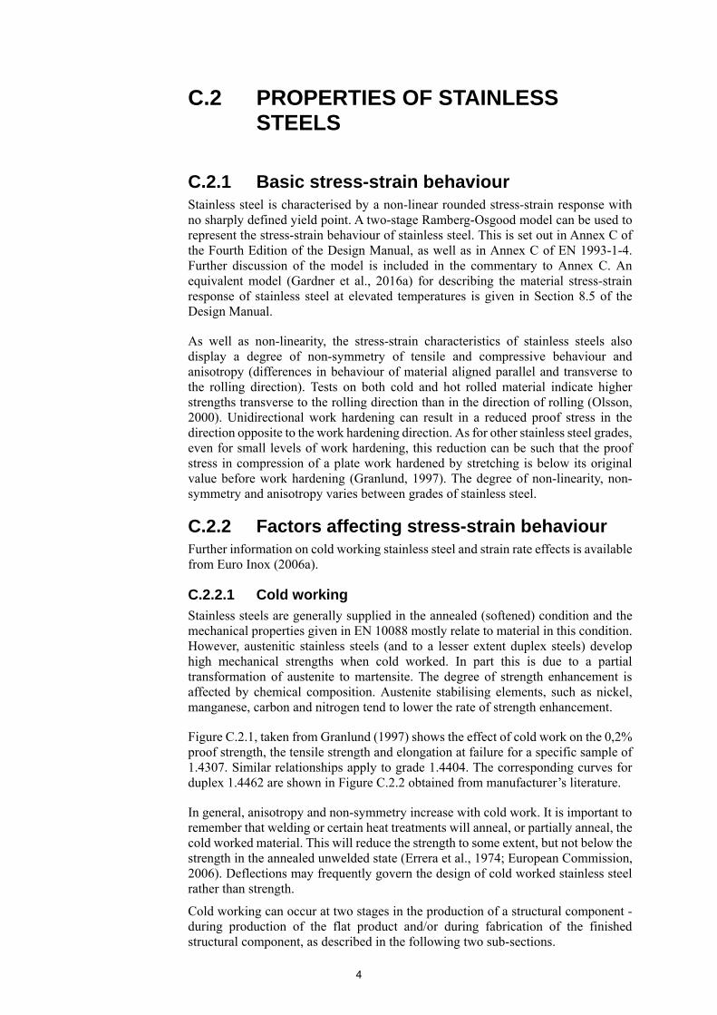
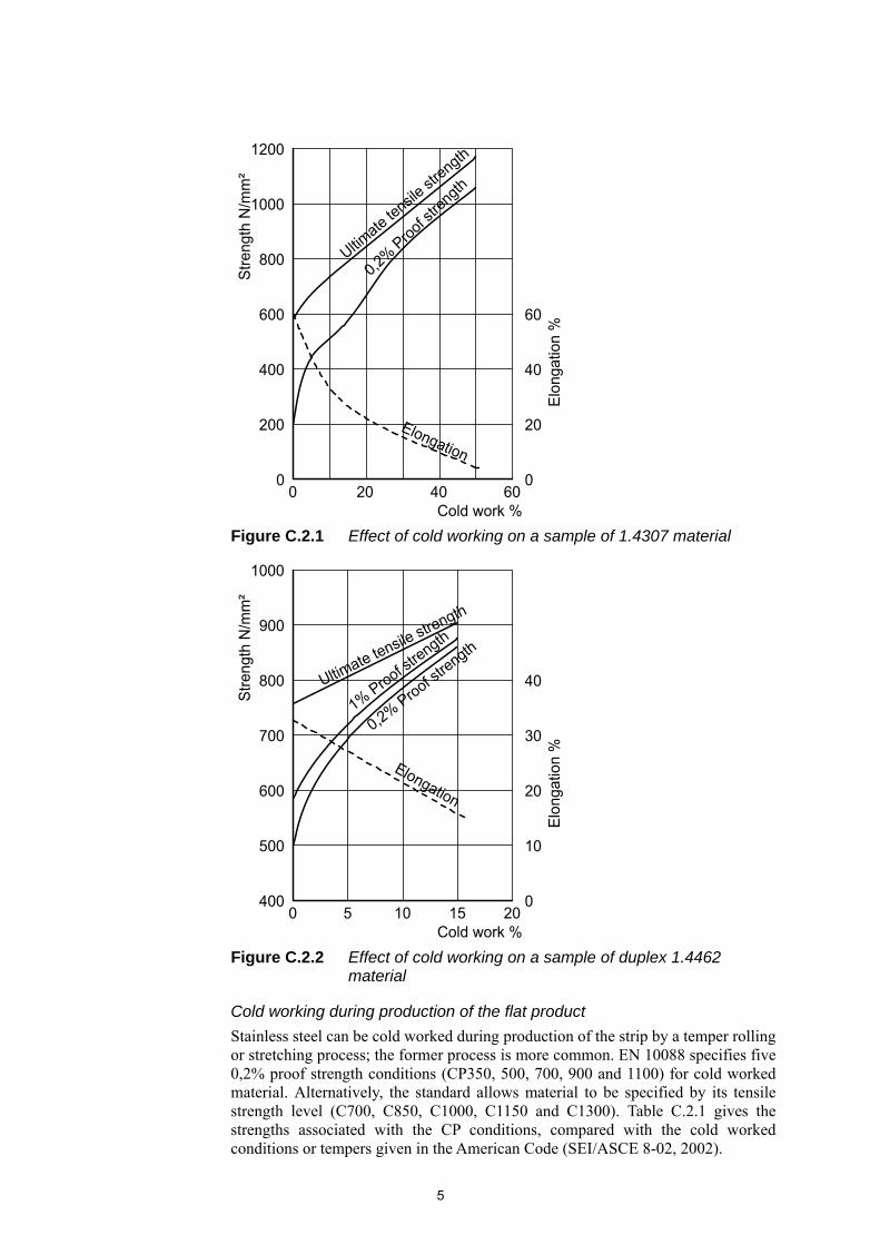
Figure C.2.1, taken from Granlund (1997) shows the effect of cold work on the 0,2% proof strength, the tensile strength and elongation at failure for a specific sample of 1.4307. Similar relationships apply to grade 1.4404. The corresponding curves for duplex 1.4462 are shown in Figure C.2.2 obtained from manufacturer’s literature.
In general, anisotropy and non-symmetry increase with cold work. It is important to remember that welding or certain heat treatments will anneal, or partially anneal, the cold worked material. This will reduce the strength to some extent, but not below the strength in the annealed unwelded state (Errera et al., 1974; European Commission, 2006). Deflections may frequently govern the design of cold worked stainless steel rather than strength.
Cold working can occur at two stages in the production of a structural component - during production of the flat product and/or during fabrication of the finished structural component, as described in the following two sub-sections.
5
Cold working during production of the flat product
Stainless steel can be cold worked during production of the strip by a temper rolling or stretching process; the former process is more common. EN 10088 specifies five 0,2% proof strength conditions (CP350, 500, 700, 900 and 1100) for cold worked material. Alternatively, the standard allows material to be specified by its tensile strength level (C700, C850, C1000, C1150 and C1300). Table C.2.1 gives the strengths associated with the CP conditions, compared with the cold worked conditions or tempers given in the American Code (SEI/ASCE 8-02, 2002).
Figure C.2.1 Effect of cold working on a sample of 1.4307 material
Figure C.2.2 Effect of cold working on a sample of duplex 1.4462 material
0
800S
tren
gth
N/m
m²
Elo
ngat
ion
%
0
Cold work %
1200
1000
600
400
200
020 6040
Elongation
Ultimate te
nsile st
rength
0,2%
Pro
of str
ength
20
40
60
20151050
1000
900
800
700
600
400
500
Str
engt
h N
/mm
²
Elo
ngat
ion
%
40
30
20
10
0
Cold work %
Ultimate tensile strength
Elongation
1% Proof stre
ngth
0,2% Proof s
trength
6
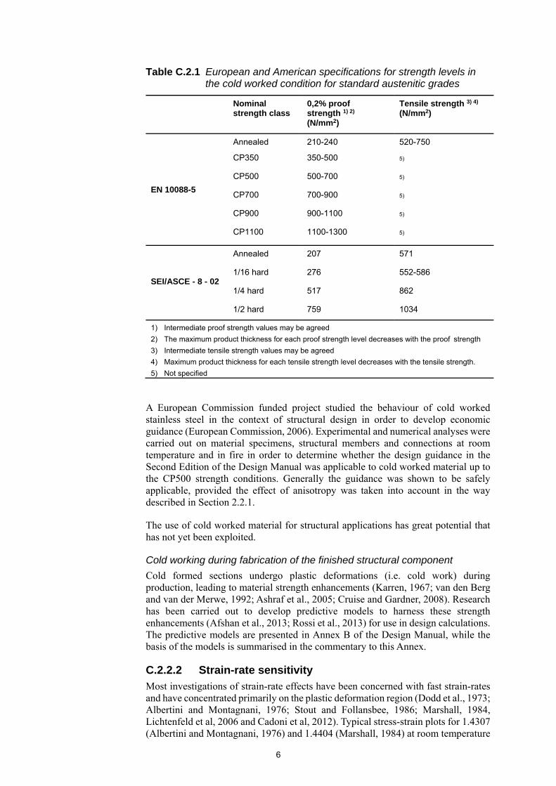
Table C.2.1 European and American specifications for strength levels in the cold worked condition for standard austenitic grades
Nominal strength class
0,2% proof strength 1) 2) (N/mm2)
Tensile strength 3) 4) (N/mm2)
EN 10088-5
Annealed 210-240 520-750
CP350 350-500 5)
CP500 500-700 5)
CP700 700-900 5)
CP900 900-1100 5)
CP1100 1100-1300 5)
SEI/ASCE - 8 - 02
Annealed 207 571
1/16 hard 276 552-586
1/4 hard 517 862
1/2 hard 759 1034
1) Intermediate proof strength values may be agreed
2) The maximum product thickness for each proof strength level decreases with the proof strength
3) Intermediate tensile strength values may be agreed
4) Maximum product thickness for each tensile strength level decreases with the tensile strength.
5) Not specified
A European Commission funded project studied the behaviour of cold worked stainless steel in the context of structural design in order to develop economic guidance (European Commission, 2006). Experimental and numerical analyses were carried out on material specimens, structural members and connections at room temperature and in fire in order to determine whether the design guidance in the Second Edition of the Design Manual was applicable to cold worked material up to the CP500 strength conditions. Generally the guidance was shown to be safely applicable, provided the effect of anisotropy was taken into account in the way described in Section 2.2.1.
The use of cold worked material for structural applications has great potential that has not yet been exploited.
Cold working during fabrication of the finished structural component
Cold formed sections undergo plastic deformations (i.e. cold work) during production, leading to material strength enhancements (Karren, 1967; van den Berg and van der Merwe, 1992; Ashraf et al., 2005; Cruise and Gardner, 2008). Research has been carried out to develop predictive models to harness these strength enhancements (Afshan et al., 2013; Rossi et al., 2013) for use in design calculations. The predictive models are presented in Annex B of the Design Manual, while the basis of the models is summarised in the commentary to this Annex.
C.2.2.2 Strain-rate sensitivity
Most investigations of strain-rate effects have been concerned with fast strain-rates and have concentrated primarily on the plastic deformation region (Dodd et al., 1973; Albertini and Montagnani, 1976; Stout and Follansbee, 1986; Marshall, 1984, Lichtenfeld et al, 2006 and Cadoni et al, 2012). Typical stress-strain plots for 1.4307 (Albertini and Montagnani, 1976) and 1.4404 (Marshall, 1984) at room temperature

7
are given in Figure C.2.3. More recent test results are shown in Figure C.2.4 and Figure C.2.5 (SCI, 1999). (The cyclic fluctuations in the 0 to 20% strain range in these latter two Figures are due to the dynamic response of the testing machine.) The Figures show that stainless steels have a strong strain rate dependency; strengths are increased (particularly in the region of the 0,2% proof strain) and the rupture strain reduced at higher strain rates. In the design of stainless steel blast walls, where the predominant loading is at a high strain rate, it is customary to apply a strain rate enhancement factor to the design strength in order to take advantage of the increase in strength at higher strain rates.
Figure C.2.3 Strain rate effects on grades 1.4307 and 1.4404
Figure C.2.4 Strain rate effects on grade 1.4404
15 30 45 60 75Strain %
800
600
400
200
0
52 1
4
3
15 30 45 60 75Strain %
800
600
400
200
0
134
2
- 1
- 1
1.4307
1.4404
Str
ess
(N/m
m²)
Str
ess
(N/m
m²)
Curve Strain rate (sec )
Curve Strain rate (sec )
12345
1234
- 4101050140502
- 2
- 20,4 x 101544420
00 5 10 15 20 25 30 35 40 45 50 55 60
Strain %
Str
ess
(N/m
m²)
100
200
300
400
500
600
700
800
y. -1
.
u-1
.
u-1
. -1
y- 4
- 4
Low strain rate
High strain rate
= 6,91 s
= 21,3 s
= 1,38 x 10 s
= 2,77 x 10 s
8
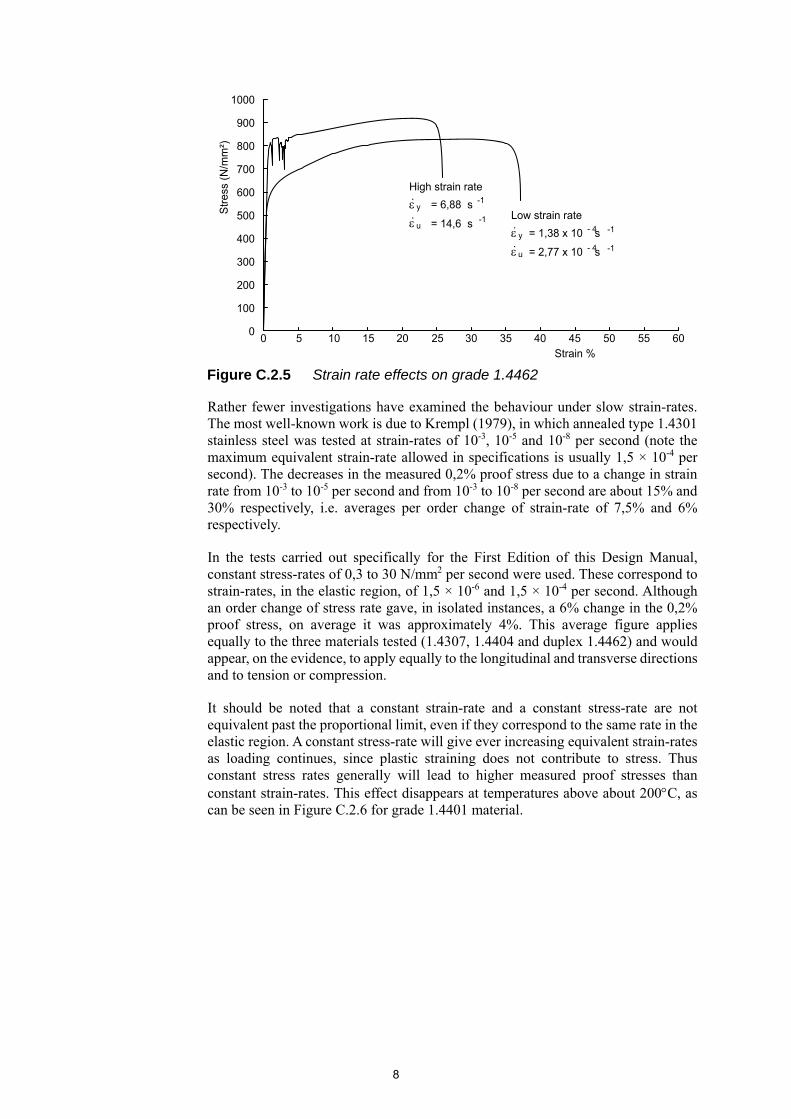
Rather fewer investigations have examined the behaviour under slow strain-rates. The most well-known work is due to Krempl (1979), in which annealed type 1.4301 stainless steel was tested at strain-rates of 10-3, 10-5 and 10-8 per second (note the maximum equivalent strain-rate allowed in specifications is usually 1,5 × 10⁻⁴ per second). The decreases in the measured 0,2% proof stress due to a change in strain rate from 10-3 to 10-5 per second and from 10-3 to 10-8 per second are about 15% and 30% respectively, i.e. averages per order change of strain-rate of 7,5% and 6% respectively.
In the tests carried out specifically for the First Edition of this Design Manual, constant stress-rates of 0,3 to 30 N/mm2 per second were used. These correspond to strain-rates, in the elastic region, of 1,5 × 10⁻⁶ and 1,5 × 10⁻⁴ per second. Although an order change of stress rate gave, in isolated instances, a 6% change in the 0,2% proof stress, on average it was approximately 4%. This average figure applies equally to the three materials tested (1.4307, 1.4404 and duplex 1.4462) and would appear, on the evidence, to apply equally to the longitudinal and transverse directions and to tension or compression.
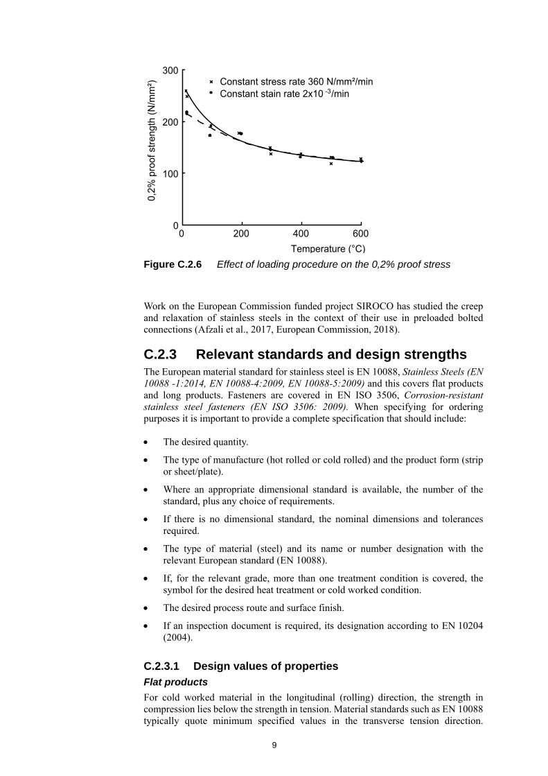
It should be noted that a constant strain-rate and a constant stress-rate are not equivalent past the proportional limit, even if they correspond to the same rate in the elastic region. A constant stress-rate will give ever increasing equivalent strain-rates as loading continues, since plastic straining does not contribute to stress. Thus constant stress rates generally will lead to higher measured proof stresses than constant strain-rates. This effect disappears at temperatures above about 200C, as can be seen in Figure C.2.6 for grade 1.4401 material.
Figure C.2.5 Strain rate effects on grade 1.4462
1000
900
800
700
600
500
400
300
200
100
0
Str
ess
(N/m
m²)
0Strain %
5 10 15 20 25 30 35 40 45 50 55 60
y. -1
.
u-1
.
u-1
. -1
y- 4
- 4
High strain rate
Low strain rate = 6,88 s
= 14,6 s = 1,38 x 10 s
= 2,77 x 10 s
9
Work on the European Commission funded project SIROCO has studied the creep and relaxation of stainless steels in the context of their use in preloaded bolted connections (Afzali et al., 2017, European Commission, 2018).
C.2.3 Relevant standards and design strengths The European material standard for stainless steel is EN 10088, Stainless Steels (EN 10088 -1:2014, EN 10088-4:2009, EN 10088-5:2009) and this covers flat products and long products. Fasteners are covered in EN ISO 3506, Corrosion-resistant stainless steel fasteners (EN ISO 3506: 2009). When specifying for ordering purposes it is important to provide a complete specification that should include:
The desired quantity.
The type of manufacture (hot rolled or cold rolled) and the product form (strip or sheet/plate).
Where an appropriate dimensional standard is available, the number of the standard, plus any choice of requirements.
If there is no dimensional standard, the nominal dimensions and tolerances required.
The type of material (steel) and its name or number designation with the relevant European standard (EN 10088).
If, for the relevant grade, more than one treatment condition is covered, the symbol for the desired heat treatment or cold worked condition.
The desired process route and surface finish.
If an inspection document is required, its designation according to EN 10204 (2004).
C.2.3.1 Design values of properties
Flat products
For cold worked material in the longitudinal (rolling) direction, the strength in compression lies below the strength in tension. Material standards such as EN 10088 typically quote minimum specified values in the transverse tension direction.
Figure C.2.6 Effect of loading procedure on the 0,2% proof stress
Temperature (°C)
6000 200 400
300
200
100
0
Constant stress rate 360 N/mm²/min-3Constant stain rate 2x10 /min
0,2%
pro
of s
tren
gth
(N/m
m²)

10
Therefore, when designing members where compression is a likely stress condition, it is necessary to factor down the quoted minimum specified 0,2% proof strength unless that strength is guaranteed in tension and compression, transverse and parallel to the rolling direction. Based on data from the European Commission funded project ‘Structural design of cold worked austenitic stainless steel’ (European Commission, 2006), the 0,2% proof strength for material in the CP500 condition was downrated from 500 to 460 N/mm2 in Table 2.3.
The American design code addresses this issue of asymmetry by giving lower strengths for material stressed in longitudinal compression (even in the annealed condition), and higher strengths for material stressed in transverse compression (Table C.2.2). Note that the longitudinal compression strength reduces relative to the transverse tensile strength as the level of cold working increases.
Table C.2.2 Specified yield strengths (N/mm2) of stainless steel in the American design code for grades 1.4301 and 1.4401
Direction of stress Annealed 1/16 hard 1/4 hard 1/2 hard
Longitudinal tension 206.9 310.3 517.1 758.5
Transverse tension 206.9 310.3 517.1 758.5
Transverse compression 206.9 310.3 620.7 827.6
Longitudinal compression 193.1 282.7 344.8 448.2
C.2.4 Physical properties Compared to carbon steels, the higher coefficients of thermal expansion for the austenitic steels (e.g. 1.4301 and 1.4401), and the lower thermal conductivities, give rise to greater welding distortions, see Section 11.6.4 in the Design Manual.
Cold working can produce phase transformation. These strain induced phases are magnetic and thus cold worked austenitic stainless steels generally have different magnetic properties from those in the annealed condition. However, unless the application is critical, moderate amounts of cold working may still provide adequate non-magnetic properties. Annealing has the effect of reversing the phase transformation and thus restoring the non-magnetic properties.
C.2.5 Effects of temperature Other properties to be considered in elevated temperature applications include creep strength, rupture strength, scaling resistance, etc. Useful information on these and other properties may be found in Inco Europe Limited (1963) and Sanderson and Llewellyn (1969). Information for cryogenic applications may be found in Sanderson and Llewellyn (1969) and Inco Europe Limited (1974).
C.2.6 Galvanizing and contact with molten zinc General guidance is given in this section of the Design Manual and no further comment is given here.
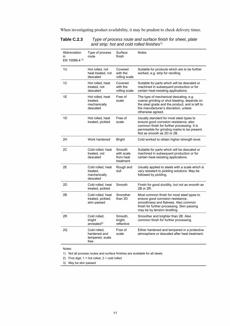
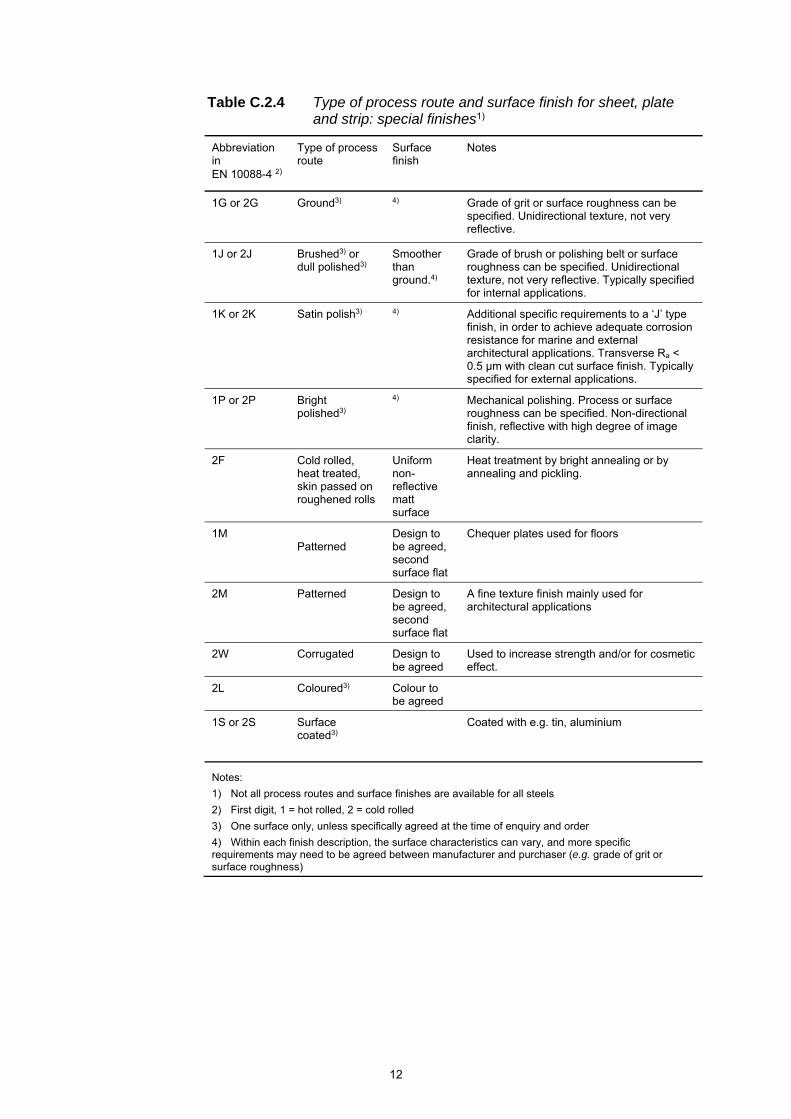
C.2.7 Availability of product forms Table C.2.3 and Table C.2.4 give the standard and special finishes available, taken from EN 10088-4 (2009). Note that the availability and cost of the finishes represented in Table C.2.4 may be considerably different from the ones in Table C.2.3; see Section 11.8 of the Design Manual. Further guidance on finishes is also available (Euro Inox, 2005a; Baddoo et al., 1995).
11
When investigating product availability, it may be prudent to check delivery times.
Table C.2.3 Type of process route and surface finish for sheet, plate and strip: hot and cold rolled finishes1)
Abbreviation in EN 10088-4 2)
Type of process route
Surface finish
Notes
1U Hot rolled, not heat treated, not descaled
Covered with the rolling scale
Suitable for products which are to be further worked, e.g. strip for rerolling
1C Hot rolled, heat treated, not descaled
Covered with the rolling scale
Suitable for parts which will be descaled or machined in subsequent production or for certain heat-resisting applications.
1E Hot rolled, heat treated, mechanically descaled
Free of scale
The type of mechanical descaling, e.g. coarse grinding or shot blasting, depends on the steel grade and the product, and is left to the manufacturer’s discretion, unless otherwise agreed.
1D Hot rolled, heat treated, pickled
Free of scale
Usually standard for most steel types to ensure good corrosion resistance; also common finish for further processing. It is permissible for grinding marks to be present. Not as smooth as 2D or 2B.
2H Work hardened Bright Cold worked to obtain higher strength level.
2C Cold rolled, heat treated, not descaled
Smooth with scale from heat treatment
Suitable for parts which will be descaled or machined in subsequent production or for certain heat-resisting applications.
2E Cold rolled, heat treated, mechanically descaled
Rough and dull
Usually applied to steels with a scale which is very resistant to pickling solutions. May be followed by pickling.
2D Cold rolled, heat treated, pickled
Smooth Finish for good ductility, but not as smooth as 2B or 2R.
2B Cold rolled, heat treated, pickled, skin passed
Smoother than 2D
Most common finish for most steel types to ensure good corrosion resistance, smoothness and flatness. Also common finish for further processing. Skin passing may be by tension levelling.
2R Cold rolled, bright annealed3)
Smooth, bright, reflective
Smoother and brighter than 2B. Also common finish for further processing.
2Q Cold rolled, hardened and tempered, scale free
Free of scale
Either hardened and tempered in a protective atmosphere or descaled after heat treatment.
Notes:
1) Not all process routes and surface finishes are available for all steels
2) First digit, 1 = hot rolled, 2 = cold rolled
3) May be skin passed
12
Table C.2.4 Type of process route and surface finish for sheet, plate and strip: special finishes1)
Abbreviation in EN 10088-4 2)
Type of process route
Surface finish
Notes
1G or 2G Ground3) 4) Grade of grit or surface roughness can be specified. Unidirectional texture, not very reflective.
1J or 2J Brushed3) or dull polished3)
Smoother than ground.4)
Grade of brush or polishing belt or surface roughness can be specified. Unidirectional texture, not very reflective. Typically specified for internal applications.
1K or 2K Satin polish3) 4) Additional specific requirements to a ‘J’ type finish, in order to achieve adequate corrosion resistance for marine and external architectural applications. Transverse Ra < 0.5 µm with clean cut surface finish. Typically specified for external applications.
1P or 2P Bright polished3)
4) Mechanical polishing. Process or surface roughness can be specified. Non-directional finish, reflective with high degree of image clarity.
2F Cold rolled, heat treated, skin passed on roughened rolls
Uniform non-reflective matt surface
Heat treatment by bright annealing or by annealing and pickling.
1M Patterned
Design to be agreed, second surface flat
Chequer plates used for floors
2M Patterned Design to be agreed, second surface flat
A fine texture finish mainly used for architectural applications
2W Corrugated Design to be agreed
Used to increase strength and/or for cosmetic effect.
2L Coloured3) Colour to be agreed
1S or 2S Surface coated3)
Coated with e.g. tin, aluminium
Notes:
1) Not all process routes and surface finishes are available for all steels
2) First digit, 1 = hot rolled, 2 = cold rolled
3) One surface only, unless specifically agreed at the time of enquiry and order
4) Within each finish description, the surface characteristics can vary, and more specific requirements may need to be agreed between manufacturer and purchaser (e.g. grade of grit or surface roughness)

13
C.2.8 Life cycle costing and environmental impact
Manufacturers of construction products, designers, users and owners of buildings and structures need information that will enable them to make informed decisions about environmental impact. Environmental impacts of buildings are commonly quantified and assessed using life cycle assessment (LCA) techniques and frequently communicated via environmental product declarations (EPD). In Europe, EPDs for construction works are derived according to the requirements of EN 15804 (2013), which is part of a suite of standards for the assessment of the sustainability of construction works at both product and building level. The suite of standards includes
EN 15643-1:2010 Sustainability of construction works. Sustainability assessment of buildings. General framework
EN 15643-2:2011 Sustainability of construction works. Assessment of buildings. Framework for the assessment of environmental performance
EN 15978:2011 Sustainability of construction works. Assessment of environmental performance of buildings. Calculation method
CEN/TR 15941 CEN/TR 15941:2010 Sustainability of construction works. Environmental product declarations. Methodology for selection and use of generic data
EN 15942:2011 Sustainability of construction works. Environmental product declarations. Communication format business-to-business
Outokumpu has published EPDs for stainless steel products (hot rolled, cold rolled, long products and rebar) (Outokumpu, 2013b).
Data provided in EPDs are based on LCA, and the information may cover different life cycle phases, for example:
“cradle-to-gate” i.e. the product stage only: raw material supply, transport, manufacturing, and associated processes are included (modules A1 to A3 in EN 15804)
“cradle-to-gate with options” contains the product stage (modules A1-3). Installation into the building (modules A4-5), use, maintenance, repair, replacements and refurbishment (modules B1-7), demolition, waste processing and disposal (modules C1-4), reuse, recovery and/or recycling potential expressed as net impacts and benefits (module D) are all optional modules. (Module D allows benefits to be taken now for the eventual reuse or recycling of material in the future, which is a very significant advantage for stainless steel.)
“cradle-to-cradle” includes all modules except module D.
A study by Rossi (2014) compares the environmental impact of four grades of stainless steel (1.4301, 1.4401, 1.4016 and 1.4462), considering the cradle-to gate with options.
The International Stainless Steel Forum has developed a web site dedicated to up-to-date resources and papers on the sustainability of stainless steel www.sustainablestainless.org/.
14
C.3 DURABILITY AND SELECTION OF MATERIALS
C.3.1 Introduction Stainless steels perform satisfactorily in the great majority of applications, there are potential risks with corrosion mechanisms in specific environments, particularly those containing chlorides. It is the intention of Section 3 in the Design Manual to bring to the designer an awareness of these mechanisms and the possible pitfalls in the application of stainless steel, without being unduly alarmist. Good design and correct grade selection will avoid potential problems. Useful references include The Outokumpu Corrosion Handbook (Outokumpu, 2009) and Stainless steels for architecture building and construction: Guidelines for corrosion prevention (Houska, 2014). A recent European project included an extensive study of the corrosion resistance of ferritic stainless steels (European Commission, 2015).
C.3.2 Types of corrosion The corrosion resistance of stainless steel arises from a passive, chromium-rich, oxide film that forms on the surface of the steel. The film is strongly adherent, usually self-repairing, and generally highly resistant to chemical attack. If it is broken down and not repaired, corrosion will occur.
The presence of oxygen is essential to the corrosion resistance of a stainless steel. The corrosion resistance is at its maximum when the steel is boldly exposed and the surface is maintained free of deposits by a flowing bulk environment (e.g. rainwater). Covering a portion of the surface, for example by biofouling, painting, or installing a gasket, produces an oxygen-depleted region under the covered region, and a higher level of alloy content is required to prevent corrosion.
Molybdenum is used to increase the stability of the film and thus grades 1.4401 and 1.4404 exhibit greater corrosion resistance than grades 1.4301 and 1.4307. Duplex 1.4462 is even better in terms of corrosion resistance.
General (uniform) corrosion
Passivity exists under certain conditions for particular environments. When conditions are favourable for maintaining passivity, stainless steels exhibit extremely low corrosion rates. If passivity is destroyed under certain conditions that do not permit the restoration of the passive film (as may occur in strongly acid or alkaline environments), stainless steel will corrode, much like a carbon or low alloy steel.
Abrasive corrosion
Abrasive corrosion could occur, for instance, in flowing water containing suspended particles such as in some rivers, coastal areas, etc.
Pitting corrosion
Pitting initiation is influenced by surface conditions, including the presence of deposits, and by temperature. For the types of environment for which this Design Manual was prepared, resistance to pitting is best characterised by service experience.
Crevice corrosion
A crevice will only present a corrosion hazard if it is wide enough to permit entry of a liquid and sufficiently narrow to maintain a stagnant zone. For these reasons
15
crevice corrosion will usually only occur at openings a few tens of microns or less in width and rarely within gaps that are several millimetres wide. As with other types of corrosion, crevice corrosion cannot occur without a liquid corrodant; if the liquid is excluded from the crevice no trouble will occur.
It is therefore possible for some gaps, which may be defined as crevices, to be relatively safe but a precise decision is not really possible without experience of the situation involved and thus the general tendency is to recommend their elimination. It may be possible to seal crevices (see Section 3.4 of the Design Manual).
Intergranular corrosion (sensitisation)
The fact that the selected grades do not generally become sensitised is beneficial not only for intergranular corrosion but also for other forms of corrosion. This is because the low carbon content limits the amount of chromium that is precipitated out, leaving a relatively high amount in solution for imparting corrosion resistance.
Where service temperatures of more than 425°C are required, consideration should be given to the so-called stabilised grades. These grades, commonly designated 1.4541 and 1.4571, have additions of titanium which preferentially form carbide precipitates to chromium.
Bimetallic corrosion
Under certain circumstances, most metals can be vulnerable to this form of corrosion (BS PD 6486, 1979). The severity of bimetallic corrosion depends on the electrolyte; increased conductivity of the electrolyte will raise the corrosion rate. Brackish waters and seawaters are very conductive. Fresh water can also be very conductive depending on the level of contaminants; rain can absorb atmospheric pollutants and may become conductive. The period of exposure to the electrolyte, including the effectiveness of drainage and evaporation and the retention of moisture in crevices, is an important parameter.
Stress corrosion cracking
It is difficult to predict when stress corrosion cracking (SCC) may occur but experience would suggest that it should certainly be considered for marine and other environments contaminated by chloride ions, as these are known to promote SCC.
As for other forms of corrosion the period of wetness (including that due to condensation) can affect SCC, as does the concentration of the damaging species (e.g. chloride). It should be noted that SCC can be caused by solutions having initially low chloride concentrations, even as low as parts-per-million levels. This is because the solution may become concentrated due to evaporation.
Detailed guidance on the use of stainless steel in swimming pool buildings, taking due regard of the risk of SCC was published in 2013 (Euro Inox, 2013).
C.3.3 Corrosion in selected environments General guidance is given in this section of the Design Manual and no further comment is given here.
C.3.4 Design for corrosion control Many of the recommendations given in this section of the Design Manual are simply a matter of good engineering practice and also apply to the design of carbon steel structures. However, they assume more importance with stainless steel structures.

16
Fabrication processes play an important part in corrosion resistance and reference should also be made to Section 11 of the Design Manual.
C.3.5 Selection of materials Grade selection may be carried out in accordance with the procedure given in Section 3.5 (taken from EN 1993-1-4), noting the limitations of the approach detailed below.
The approach considers all corrosion risks including pitting, crevice corrosion and Stress Corrosion Cracking (SCC) of stainless steels that may affect integrity of load bearing parts. The procedure assumes that no corrosion of stainless steel will occur that would impact the structural integrity of a load bearing component. This is a conservative approach. However, in some instances cosmetic corrosion (staining or minor pitting) could occur. These effects may be unsightly and unacceptable where appearance is important but are not detrimental to integrity.
Where high quality of appearance is important, additional requirements may be required, for example a higher alloy grade or a specific surface finish. These are beyond the scope of this grade selection procedure and specialist advice should be obtained.
The grade selection procedure is not appropriate for selection of stainless steels for use in chemical processes where the steel is in direct, intentional contact with the process materials during normal service conditions (e.g. the selection of steel for process piping containing specific chemicals). The use of stainless steel for structures supporting such process equipment, or as structural frames for building housing such equipment, is permitted on the assumption that any contact with process fluids would be of short duration due to some fault or accidental condition.
The limitations as stated could be interpreted as meaning stainless steel cannot be used in contact with concrete (which has a pH > 9) or some timbers (where the pH may be < 4). In practice there are unlikely to be problems with either interface however, EN 1992 and EN 1996 should give appropriate rules for stainless steel in contact with concrete and masonry respectively.
The grade selection procedure is suitable for environments found within Europe. This is an important limitation because the selection procedure and outcomes are based on operating experience, exposure test site data and chloride distribution modelling for Europe only. The basic principles of the procedure are applicable to other regions but the outcomes in terms of appropriate alloys may be different. Specialist advice should be obtained for locations outside Europe.
Selecting materials for coastal areas can be very difficult due to locally generated micro environments caused by a combination of ground topography, prevailing wind direction/strength and transport of air borne chloride from the sea. The grade selection procedure defaults to a worst case and may be conservative in some instances. National Annexes may recommend less conservative values based on local operating experience.
In Table 3.3, an ‘internally controlled environment’ assumes the service environment is air conditioned or otherwise controlled with no risk of exposure to chlorides. Care is needed in selecting this condition for industrial buildings with large doors or openings which may expose the internal spaces to the external environment. For such conditions, select the “Low risk of exposure”. Note that choosing this category gives a CRC of I. The alloys given CRC I may not be readily available and the user is recommended to use CRC II for this condition.

17
In the calculation of in Table 3.3, for the avoidance of doubt, the risk of exposure to chlorides is determined by distance from the sea OR distance from roads using de-icing salts.
For nearly all applications it is reasonable to assume that is “Low risk of exposure” unless there is reliable data to suggest otherwise. Road tunnels should be assumed to be “High risk of exposure” unless reliable data suggests otherwise.
takes into account the cleaning regime or exposure to washing by rain. There can be significant benefit to durability if stainless steel is regularly cleaned and a specified cleaning regime may result in the selection of a leaner (and therefore cheaper alloy). However, if it is assumed that cleaning will occur but subsequently does not, this may have a significantly detrimental effect on corrosion performance. Designers should therefore be realistic in assumptions regarding cleaning and note that the onus is on the designer to clearly specify the cleaning requirements (see the note to Table 3.3). A conservative approach to assume no cleaning as a default condition.
Table 3.5 gives five CRC which contain a number of stainless steel grades that offer appropriate durability for that class. However, different steel producers/suppliers have different preferences for the alloys referenced which may limit availability and product forms. The designer may avoid this problem by specification of the CRC rather than an individual grade from that class and allow the supplier to select the individual grade.
Table 3.6 places considerable restrictions on materials for use in pool atmospheres, essentially limiting choice to a few super austenitic alloys. This conservatism reflects a number of fatal failures of load bearing stainless steels in pool atmospheres in mainland Europe. A designer may be think that the use of a cleaning regime may permit the use of leaner, more cost effective alloys. However, the designer would take responsibility for the detailed specification of the cleaning regime and should consider the likelihood of a building owner undertaking such cleaning. The required frequency of cleaning (every week) is probably impractical in most circumstances. It is also impractical to clean all surfaces on threaded parts. Reliance on cleaning by a building owner is therefore not recommended.

18
C.4 BASIS OF DESIGN
C.4.1 General requirements The aims in designing a stainless steel structure are no different from those in carbon steel structures. That is a safe, serviceable and durable structure should result. As well as the more obvious considerations such as strength and stability, the design of a structure should take account of the following:
Safe transport and handling.
Safe means of interconnection.
Stability during erection.
One designer should be responsible for ensuring the overall stability of the structure, particularly if stainless steel is used in conjunction with other materials. In the design of the stainless steel structure, the assumed restraint and stability afforded by other materials should be clearly stated and made known to the engineer responsible.
C.4.2 Limit state design In limit state design, the performance or capacity of the structure or its components is assessed against various criteria (the limit states) at appropriate load levels. For carbon steel structures, the designer is mainly concerned with the ultimate limit states, which potentially could lead to loss of life, and serviceability limit states, which could lead to loss of function. The reduction in structural performance of carbon steel building structures due to corrosion is not usually specifically considered by the structural designer, reliance instead being place upon paint or other protective coatings. Where corrosion is likely to affect performance, as for marine or offshore structures, the use of a sacrificial corrosion allowance on the thickness or of cathodic protection is common. However, for stainless steel, anti-corrosion measures should form an integral part of the design, from material selection to detailing of member and joints, and must be carried through fabrication and erection. Thus, in Section 4.2 of the Design Manual, the durability limit state is on an equal footing to the ultimate and serviceability limit states.
The values of the partial factor for resistance, M, given in Table 4.1 are the recommended values in EN 1993-1-4. Note that certain European countries may specify modified M values in their National Annexes, and, where this is the case, these values must be used in the place of the values given in EN 1993-1-4.
C.4.3 Loading It is the responsibility of the designer to consider all load effects (dead loads, imposed loads, effects of temperature and settlement, etc.) and establish the most onerous load case for each member.
As for the M factors, different values of F may be set in the National Annex for the country for which the structure is being designed.
19
C.5 CROSS-SECTION DESIGN
C.5.1 General Section 5 of the Design Manual is concerned with the local (cross-section) behaviour of members; overall buckling is addressed in Section 6. For a member not susceptible to overall buckling, e.g. a stub column or a laterally restrained beam, the resistance is solely dictated by local behaviour and therefore the provisions of Section 5 are sufficient for its determination.
The local capacity of a member, i.e. the cross-sectional resistance, is dependent on the behaviour of the constituent elements that make up the cross-section. Elements, and hence the cross-section, may be affected by certain structural phenomena, such as local buckling and shear lag, which reduce their effectiveness to carry load. As in the case of carbon steel rules, these phenomena are catered for in the Design Manual by the use of effective widths.
For the cross-section design rules in the First Edition of the Design Manual, carbon steel codes (EN 1993-1-1:2005; BS 5950-1:2000; BS 5950-5:1998), stainless steel codes (SEI/ASCE 8-02) and experimental data for stainless steel members were consulted. When revising the Design Manual for the Second Edition, further test data were available, generated in the Development of the use of stainless steel in construction project (European Commission, 2002). In addition, the ENVs for cold formed carbon steel, fire resistant design, stainless steel and plated structures were also used (ENV 1993-1-3:1996, -2:1995, -4:1996, -5:1997). When revising the Recommendations for the Third Edition, new test data were available from the Structural design of cold worked austenitic stainless steel project (European Commission, 2006) as well as parts of Eurocode 3. For this Fourth Edition, further experimental and numerical data have become of available and have been utilised, as described below.
C.5.2 Maximum width-to-thickness ratios Limiting width-to-thickness ratios are provided for various types of elements. Limits are placed not so much that thinner sheets cannot be used but because the rules may become inaccurate. The ratios have been set as the smaller of the limiting values given in EN 1993-1-3 for cold formed, thin gauge carbon steel and the American cold formed stainless steel specification SEI/ASCE 8-02.
It can be argued that at the low stresses associated with the high slendernesses, carbon and stainless steel elements should behave very similarly and thus justify the use of the greater ratios of EN 1993-1-3 for all stainless steel elements. It is, however, considered prudent to use the values in SEI/ASCE 8-02, where they are more limiting, due to the paucity of data relating to stainless steel and the fact that experience has already been gained with these values in a previous version of the American provisions.
The note concerning / ratios and visual distortion is based on SEI/ASCE 8-02 and the / values are derived from the critical stress in the flange elements.

20
C.5.3 Classification of cross-sections C.5.3.1 General The classification of cross-sections according to their ability to resist local buckling and to sustain load with increased deformation has proved a useful concept for the design of carbon steel members and indeed for members of other metals. Classification is usually defined in terms of a cross-section’s moment resistance, i.e. whether it can reach the plastic moment (with and without rotation capacity), the elastic moment, or a lower value due to the onset of local buckling.
Since the definition of yield strength of non-linear materials is rather arbitrary, so are the definitions of yield and plastic moments for members composed of such materials. The obvious definitions to apply are the elastic and plastic section moduli multiplied by a proof stress, conventionally defined as the stress giving a 0,2% permanent strain.
Table 5.2 gives limiting width-to-thickness ratios (slenderness limits) for the classification of elements according to their type and to the applied stress distribution. The slenderness limits are the same as those given in EN 1993-1-4 and differ slightly from those given in EN 1993-1-1 for carbon steel, reflecting differences in the material stress-strain response, available test data and factors influencing the assessment of reliability. The derivation of the slenderness limits to define the four classes of cross-section has been described in Gardner and Theofanous (2008).
The absence of a sharply defined yield point and the extensive strain hardening associated with stainless steel renders the process of cross-section classification less applicable to stainless steel than it is to hot rolled carbon steel. Furthermore, with the maximum attainable stress being the 0,2% proof stress, design efficiency, particularly in the case of stocky cross-sections, can be significantly hampered through its use. The Continuous Strength Method (CSM) is a deformation based design approach that allows for strain hardening, overcomes the limitations of cross-section classification, and leads to substantially enhanced design efficiency. Cross-section design using the continuous strength method is set out in Annex D of the Design Manual.
C.5.3.2 Classification limits for parts of cross-sections
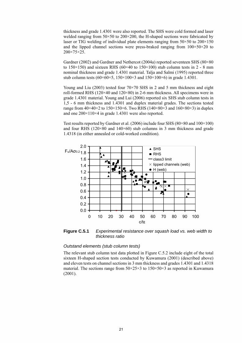
The classification limits in the Design Manual have been verified against all available experimental results to ensure safe design. These include both stub column tests, by means of which the limits for Class 3 parts (internal, outstand, CHS, angles) under pure compression are verified, and in-plane bending tests, by means of which the Class 3 and 2 limits are assessed. Since plastic design is not currently allowed for stainless steel structures, the Class 1 limit is not discussed herein, but has been assessed in Gardner and Theofanous (2008) and Theofanous et al. (2014). For both stub column and in-plane bending tests, the ultimate resistance normalised by the relevant theoretical resistance is plotted against the slenderness of the most slender element of the cross-section in the graphs below. The relevant class limit is also depicted in the graphs.
Internal elements (stub column tests)
Seven sources of data exist for internal elements under pure compression (see Figure C.5.1). These include SHS, RHS, lipped channel sections and H-shaped sections.
Two 80×80×3 SHS stub column tests were reported by Rasmussen and Hancock (1990). Kuwamura (2001) tested twelve SHS, sixteen H-shaped sections and eight lipped channel sections in 3 mm nominal thickness and grades 1.4301 and 1.4318 material. Four more tests on lipped channel section stub columns in 1 mm nominal
21
thickness and grade 1.4301 were also reported. The SHS were cold formed and laser welded ranging from 50×50 to 200×200, the H-shaped sections were fabricated by laser or TIG welding of individual plate elements ranging from 50×50 to 200×150 and the lipped channel sections were press-braked ranging from 100×50×20 to 200×75×25.
Gardner (2002) and Gardner and Nethercot (2004a) reported seventeen SHS (80×80 to 150×150) and sixteen RHS (60×40 to 150×100) stub column tests in 2 - 8 mm nominal thickness and grade 1.4301 material. Talja and Salmi (1995) reported three stub column tests (60×60×5, 150×100×3 and 150×100×6) in grade 1.4301.
Young and Liu (2003) tested four 70×70 SHS in 2 and 5 mm thickness and eight roll-formed RHS (120×40 and 120×80) in 2-6 mm thickness. All specimens were in grade 1.4301 material. Young and Lui (2006) reported six SHS stub column tests in 1,5 - 6 mm thickness and 1.4301 and duplex material grades. The sections tested range from 40×40×2 to 150×150×6. Two RHS (140×80×3 and 160×80×3) in duplex and one 200×110×4 in grade 1.4301 were also reported.
Test results reported by Gardner et al. (2006) include four SHS (80×80 and 100×100) and four RHS (120×80 and 140×60) stub columns in 3 mm thickness and grade 1.4318 (in either annealed or cold-worked condition).
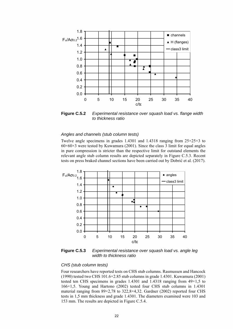
Outstand elements (stub column tests)
The relevant stub column test data plotted in Figure C.5.2 include eight of the total sixteen H-shaped section tests conducted by Kuwamura (2001) (described above) and eleven tests on channel sections in 3 mm thickness and grades 1.4301 and 1.4318 material. The sections range from 50×25×3 to 150×50×3 as reported in Kuwamura (2001).
Figure C.5.1 Experimental resistance over squash load vs. web width to thickness ratio
0.0
0.2
0.4
0.6
0.8
1.0
1.2
1.4
1.6
1.8
2.0
0 10 20 30 40 50 60 70 80 90 100c/tε
Fu/Aσ0.2SHSRHSclass3 limitlipped channels (web)H (web)
22
Angles and channels (stub column tests)
Twelve angle specimens in grades 1.4301 and 1.4318 ranging from 25×25×3 to 60×60×3 were tested by Kuwamura (2001). Since the class 3 limit for equal angles in pure compression is stricter than the respective limit for outstand elements the relevant angle stub column results are depicted separately in Figure C.5.3. Recent tests on press braked channel sections have been carried out by Dobrić et al. (2017).
CHS (stub column tests)
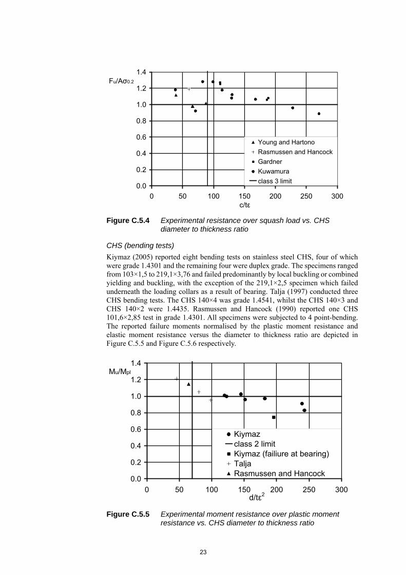
Four researchers have reported tests on CHS stub columns. Rasmussen and Hancock (1990) tested two CHS 101.6×2.85 stub columns in grade 1.4301. Kuwamura (2001) tested ten CHS specimens in grades 1.4301 and 1.4318 ranging from 49×1,5 to 166×1,5. Young and Hartono (2002) tested four CHS stub columns in 1.4301 material ranging from 89×2,78 to 322,8×4,32. Gardner (2002) reported four CHS tests in 1,5 mm thickness and grade 1.4301. The diameters examined were 103 and 153 mm. The results are depicted in Figure C.5.4.
Figure C.5.2 Experimental resistance over squash load vs. flange width to thickness ratio
Figure C.5.3 Experimental resistance over squash load vs. angle leg width to thickness ratio
0.0
0.2
0.4
0.6
0.8
1.0
1.2
1.4
1.6
1.8
0 5 10 15 20 25 30 35 40c/tε
Fu/Aσ0.2
channels
H (flanges)
class3 limit
0.0
0.2
0.4
0.6
0.8
1.0
1.2
1.4
1.6
1.8
0 5 10 15 20 25 30 35 40c/tε
Fu/Aσ0.2 angles
class3 limit
23
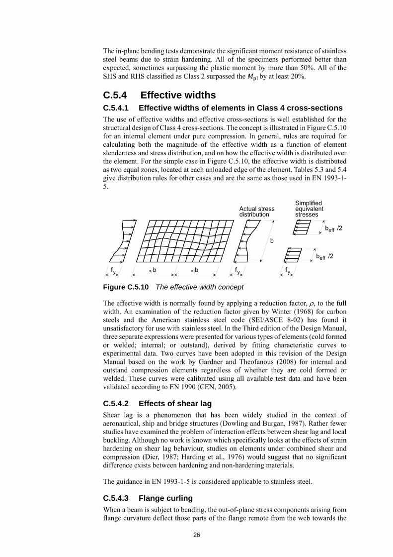
CHS (bending tests)
Kiymaz (2005) reported eight bending tests on stainless steel CHS, four of which were grade 1.4301 and the remaining four were duplex grade. The specimens ranged from 103×1,5 to 219,1×3,76 and failed predominantly by local buckling or combined yielding and buckling, with the exception of the 219,1×2,5 specimen which failed underneath the loading collars as a result of bearing. Talja (1997) conducted three CHS bending tests. The CHS 140×4 was grade 1.4541, whilst the CHS 140×3 and CHS 140×2 were 1.4435. Rasmussen and Hancock (1990) reported one CHS 101,6×2,85 test in grade 1.4301. All specimens were subjected to 4 point-bending. The reported failure moments normalised by the plastic moment resistance and elastic moment resistance versus the diameter to thickness ratio are depicted in Figure C.5.5 and Figure C.5.6 respectively.
Figure C.5.4 Experimental resistance over squash load vs. CHS diameter to thickness ratio
Figure C.5.5 Experimental moment resistance over plastic moment resistance vs. CHS diameter to thickness ratio
0.0
0.2
0.4
0.6
0.8
1.0
1.2
1.4
0 50 100 150 200 250 300c/tε
Fu/Aσ0.2
Young and Hartono
Rasmussen and Hancock
Gardner
Kuwamura
class 3 limit
0.0
0.2
0.4
0.6
0.8
1.0
1.2
1.4
0 50 100 150 200 250 300d/tε2
Mu/Mpl
Kiymazclass 2 limitKiymaz (failiure at bearing)TaljaRasmussen and Hancock

24
Internal elements (bending tests)
Six series of tests on beams comprising internal elements exist, including both SHS and RHS. Real (2001) reported two SHS 80×80×3 and two RHS 120×80×4 simply supported bending tests in grade 1.4301. Three SHS 60×60×5, three RHS 150x100x3 and three RHS 150×100×6 in grade 1.4301 bending tests were reported by Talja and Salmi (1995). Gardner (2002) reported five SHS (80×80 to 100×100) and four RHS (60×40 to 100×50) in-plane bending tests in 2-8 mm nominal thickness and grade 1.4301 material. Zhou and Young (2005) reported eight SHS bending tests (from 40×40 to 150×150) in 1.5 - 6 mm thickness and seven RHS bending tests (100×50×2 to 200×110×4). All specimens were in 1.4301 and duplex grades. Gardner et al. (2006) tested two SHS 100×100×3 and four RHS beams (120×80×3 and 140×60×3) in grade 1.4318 (both annealed and cold-worked condition). One SHS 80×80×3 beam test reported by Rasmussen and Hancock (1990) is also included in Figure C.5.7 and Figure C.5.8, the first depicting test moment normalised by plastic moment and the second by the elastic moment versus flange width to thickness ratio.
Figure C.5.6 Experimental moment resistance over elastic moment resistance vs. CHS diameter to thickness ratio
Figure C.5.7 Experimental moment resistance over plastic moment resistance vs. flange width to thickness ratio
0.0
0.2
0.4
0.6
0.8
1.0
1.2
1.4
1.6
0 50 100 150 200 250 300d/tε2
Mu/Mel
Kiymaz
class 3 limit
Kiymaz (failiure at bearing)
Talja
Rasmussen and Hancock
0.0
0.5
1.0
1.5
2.0
0 10 20 30 40 50 60 70 80c/tε
Mu/Mpl RHS
SHS
class 2 limit

25
Outstand elements (bending tests)
Two test series comprising a total of six I-section in-plane bending tests have been reported. The specimens were subjected to four-point bending and were short enough not to be susceptible to lateral torsional buckling. Talja (1997) conducted experiments on three I-sections (160×80, 160×160 and 320×160) with 10 mm flange and 6 mm web thickness in grade 1.4301 and one I-section (160×160) with 10 mm flange and 7 mm web thickness in grade 1.4462. Real (2001) reported two tests on I 100×100 beams in 8 mm thickness. The experimental ultimate moments normalised by the plastic moment are plotted against the flange width to thickness ratio in Figure C.5.9. The Class 2 and Class 3 limits for outstand elements are also depicted.
As shown in Figure C.5.1 to Figure C.5.9, the design rules for cross-sectional classification are safe for the vast majority of the reported experimental results. All of the stub column sections consisting of flat parts classified as Class 3 or above easily surpass the squash load, as did some sections classified as Class 4. This is partly due to the effect of strain hardening.
Figure C.5.8 Experimental moment resistance over elastic moment resistance vs. flange width to thickness ratio
Figure C.5.9 Experimental moment resistance over plastic moment resistance vs. CHS diameter to thickness ratio
0.0
0.5
1.0
1.5
2.0
2.5
0 10 20 30 40 50 60 70 80c/tε
Mu/Mel RHS
SHS
class 3 limit
0.0
0.2
0.4
0.6
0.8
1.0
1.2
1.4
0 2 4 6 8 10 12 14c/tε
Mu/Mpl
Talja
Real
class 2 limit
class 3 limit
26
The in-plane bending tests demonstrate the significant moment resistance of stainless steel beams due to strain hardening. All of the specimens performed better than expected, sometimes surpassing the plastic moment by more than 50%. All of the SHS and RHS classified as Class 2 surpassed the by at least 20%.
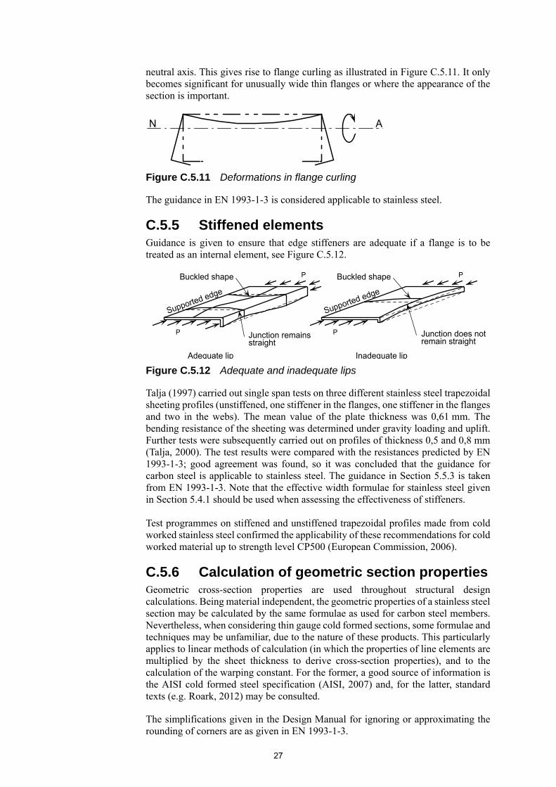
C.5.4 Effective widths C.5.4.1 Effective widths of elements in Class 4 cross-sections The use of effective widths and effective cross-sections is well established for the structural design of Class 4 cross-sections. The concept is illustrated in Figure C.5.10 for an internal element under pure compression. In general, rules are required for calculating both the magnitude of the effective width as a function of element slenderness and stress distribution, and on how the effective width is distributed over the element. For the simple case in Figure C.5.10, the effective width is distributed as two equal zones, located at each unloaded edge of the element. Tables 5.3 and 5.4 give distribution rules for other cases and are the same as those used in EN 1993-1-5.
The effective width is normally found by applying a reduction factor, , to the full width. An examination of the reduction factor given by Winter (1968) for carbon steels and the American stainless steel code (SEI/ASCE 8-02) has found it unsatisfactory for use with stainless steel. In the Third edition of the Design Manual, three separate expressions were presented for various types of elements (cold formed or welded; internal; or outstand), derived by fitting characteristic curves to experimental data. Two curves have been adopted in this revision of the Design Manual based on the work by Gardner and Theofanous (2008) for internal and outstand compression elements regardless of whether they are cold formed or welded. These curves were calibrated using all available test data and have been validated according to EN 1990 (CEN, 2005).
C.5.4.2 Effects of shear lag
Shear lag is a phenomenon that has been widely studied in the context of aeronautical, ship and bridge structures (Dowling and Burgan, 1987). Rather fewer studies have examined the problem of interaction effects between shear lag and local buckling. Although no work is known which specifically looks at the effects of strain hardening on shear lag behaviour, studies on elements under combined shear and compression (Dier, 1987; Harding et al., 1976) would suggest that no significant difference exists between hardening and non-hardening materials.
The guidance in EN 1993-1-5 is considered applicable to stainless steel.
C.5.4.3 Flange curling
When a beam is subject to bending, the out-of-plane stress components arising from flange curvature deflect those parts of the flange remote from the web towards the
Figure C.5.10 The effective width concept
b
effb /2
effb /2
Actual stressdistribution
Simplifiedequivalentstresses
b b
f f fy y y
27
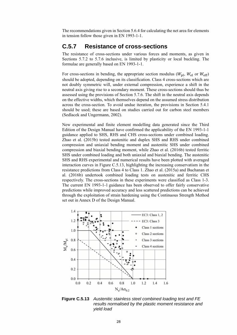
neutral axis. This gives rise to flange curling as illustrated in Figure C.5.11. It only becomes significant for unusually wide thin flanges or where the appearance of the section is important.
The guidance in EN 1993-1-3 is considered applicable to stainless steel.
C.5.5 Stiffened elements Guidance is given to ensure that edge stiffeners are adequate if a flange is to be treated as an internal element, see Figure C.5.12.
Talja (1997) carried out single span tests on three different stainless steel trapezoidal sheeting profiles (unstiffened, one stiffener in the flanges, one stiffener in the flanges and two in the webs). The mean value of the plate thickness was 0,61 mm. The bending resistance of the sheeting was determined under gravity loading and uplift. Further tests were subsequently carried out on profiles of thickness 0,5 and 0,8 mm (Talja, 2000). The test results were compared with the resistances predicted by EN 1993-1-3; good agreement was found, so it was concluded that the guidance for carbon steel is applicable to stainless steel. The guidance in Section 5.5.3 is taken from EN 1993-1-3. Note that the effective width formulae for stainless steel given in Section 5.4.1 should be used when assessing the effectiveness of stiffeners. Test programmes on stiffened and unstiffened trapezoidal profiles made from cold worked stainless steel confirmed the applicability of these recommendations for cold worked material up to strength level CP500 (European Commission, 2006).
C.5.6 Calculation of geometric section properties Geometric cross-section properties are used throughout structural design calculations. Being material independent, the geometric properties of a stainless steel section may be calculated by the same formulae as used for carbon steel members. Nevertheless, when considering thin gauge cold formed sections, some formulae and techniques may be unfamiliar, due to the nature of these products. This particularly applies to linear methods of calculation (in which the properties of line elements are multiplied by the sheet thickness to derive cross-section properties), and to the calculation of the warping constant. For the former, a good source of information is the AISI cold formed steel specification (AISI, 2007) and, for the latter, standard texts (e.g. Roark, 2012) may be consulted.
The simplifications given in the Design Manual for ignoring or approximating the rounding of corners are as given in EN 1993-1-3.
Figure C.5.11 Deformations in flange curling
Figure C.5.12 Adequate and inadequate lips
N A
Supported edge
Supported edge
Adequate lip
Buckled shapeBuckled shape
P
P
P
P
Inadequate lip
Junction remainsstraight
Junction does notremain straight
28
The recommendations given in Section 5.6.4 for calculating the net area for elements in tension follow those given in EN 1993-1-1.
C.5.7 Resistance of cross-sections The resistance of cross-sections under various forces and moments, as given in Sections 5.7.2 to 5.7.6 inclusive, is limited by plasticity or local buckling. The formulae are generally based on EN 1993-1-1.
For cross-sections in bending, the appropriate section modulus ( , or ) should be adopted, depending on its classification. Class 4 cross-sections which are not doubly symmetric will, under external compression, experience a shift in the neutral axis giving rise to a secondary moment. These cross-sections should thus be assessed using the provisions of Section 5.7.6. The shift in the neutral axis depends on the effective widths, which themselves depend on the assumed stress distribution across the cross-section. To avoid undue iteration, the provisions in Section 5.4.1 should be used; these are based on studies carried out for carbon steel members (Sedlacek and Ungermann, 2002).
New experimental and finite element modelling data generated since the Third Edition of the Design Manual have confirmed the applicability of the EN 1993-1-1 guidance applied to SHS, RHS and CHS cross-sections under combined loading. Zhao et al. (2015b) tested austenitic and duplex SHS and RHS under combined compression and uniaxial bending moment and austenitic SHS under combined compression and biaxial bending moment, while Zhao et al. (2016b) tested ferritic SHS under combined loading and both uniaxial and biaxial bending. The austenitic SHS and RHS experimental and numerical results have been plotted with averaged interaction curves in Figure C.5.13, highlighting the increasing conservatism in the resistance predictions from Class 4 to Class 1. Zhao et al. (2015a) and Buchanan et al. (2016b) undertook combined loading tests on austenitic and ferritic CHS respectively. The cross-sections in these experiments were classified as Class 1-3. The current EN 1993-1-1 guidance has been observed to offer fairly conservative predictions while improved accuracy and less scattered predictions can be achieved through the exploitation of strain hardening using the Continuous Strength Method set out in Annex D of the Design Manual.
Figure C.5.13 Austenitic stainless steel combined loading test and FE results normalised by the plastic moment resistance and yield load

29
C.6 MEMBER DESIGN
C.6.1 Introduction No matter what the material, a structural member essentially supports loads much in the same manner (e.g. by flexure or strut action). It is therefore perhaps a rather obvious statement that similar checks have to be carried out for stainless steel members as those for members in carbon steel. However, the designer should be aware of possible differences in design behaviour, such as overall frame stability that are not covered in this Design Manual.
Elastic global analysis is recommended for establishing forces and moments in members. Although in principle plastic global analysis could be used, there are presently certain difficulties to be addressed in design. These difficulties are associated with the strain hardening properties of stainless steel and in particular the moment-rotation characteristic of a stainless steel beam likewise displaying hardening behaviour. In the formation of a plastic mechanism, plastic hinges are required to undergo various degrees of rotation. Thus, where strain hardening occurs, the moments at the hinges will be above the nominal plastic moment (plastic modulus multiplied by the 0,2% proof stress) by amounts depending on the degrees of rotation. Therefore the calculation of the distribution of moments around a frame would involve kinematic considerations. With further study, it may be possible to enable bounds to be put on the additional moments (above the nominal plastic moment) to circumvent these analytical difficulties. Connections would also have to resist the enhanced moment. Alternatively, it may be possible to show that connections can provide the required rotation to realise the mechanism.
In considering member instability, reference can be made to the tangent modulus approach. This approach is adopted by the American specification for cold formed stainless steel (SEI/ASCE 8-02), and is based on replacing the Young’s modulus (in carbon steel buckling provisions) by the tangent modulus corresponding to the buckling stress in the stainless steel member. Since varies with stress and the buckling stress is a function of , the approach generally requires iterations to find the solution. The derivation can be best demonstrated by way of an example.
Suppose it is required to find the stainless steel curve corresponding to the Euler buckling curve for carbon steel columns. For carbon steel (and any linear elastic material), the limiting stress is given by:
π
Defining non-dimensional parameters:
χ and λ⁄
π
gives the limiting (Euler) curve, expressed as:
χ1
λ
For stainless steel, is replaced by the tangent modulus :
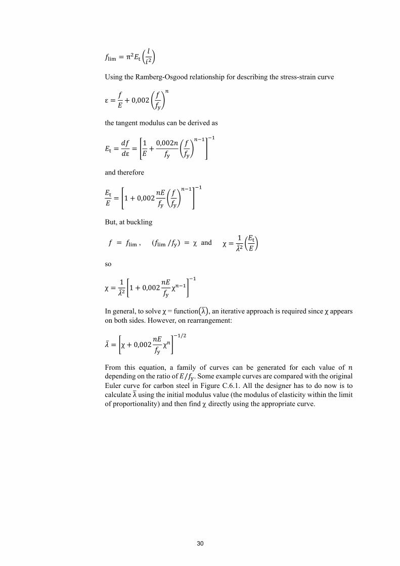
30
π
Using the Ramberg-Osgood relationship for describing the stress-strain curve
ε 0,002
the tangent modulus can be derived as
ε1 0,002
and therefore
1 0,002
But, at buckling
, ( / and χ1
so
χ1 1 0,002 χ
In general, to solve χ = function λ , an iterative approach is required since χ appears on both sides. However, on rearrangement:
χ 0,002 χ/
From this equation, a family of curves can be generated for each value of depending on the ratio of / . Some example curves are compared with the original Euler curve for carbon steel in Figure C.6.1. All the designer has to do now is to calculate λ using the initial modulus value (the modulus of elasticity within the limit of proportionality) and then find directly using the appropriate curve.

31
As can be seen, the curves with the lower value, which implies a lower limit of proportionality, diverge from the carbon steel curve at lower stresses than do the curves associated with the higher value. However, for values above about 0,9, the curves with low value lie above those of high ; this follows from the fact that the tangent modulus of the low material is greater than that of the high material in this stress range. It may be noted that a carbon steel stress-strain curve may be closely approximated by very high values (say > 30), in which case the design curve departs from the Euler curve and becomes a horizontal plateau at ≈1,0.
Although the above technique can be used to derive effective design curves, greater credence has been attached to establishing the recommended curves on the basis of available experimental data, and maintaining the general form of the buckling curves given in EN 1993-1-1, that do not require iteration.
C.6.2 Tension members In general, tension members and their connections should be detailed such that the applied load acts along the member’s centroidal axis. This is not always possible and the eccentric load will induce bending, which should be allowed for by reference to Section 5.7.6.
However, in the case of angles, recommendations are given for simple design, without taking explicit account of the moments due to eccentricity, using a modified expression for the tensile resistance in Section 7.2.3.
C.6.3 Compression members C.6.3.1 General
The various forms of buckling listed in the Design Manual are in common with those pertinent to carbon steel columns. Indeed, the behaviour of stainless steel columns and carbon steel columns can be expected to be broadly similar, differing only in quantitative aspects. It may be helpful to consider how the non-linear stress-strain curve of stainless steel affects the comparison between the buckling strengths of similar stainless steel and carbon steel columns and members in general. There are three distinct regions of slenderness:
Figure C.6.1 Effective ‘design’ curves for Euler column buckling in stainless steel
E = 200 kN/mm²f = 200 N/mm²f = 500 N/mm²
yyn = 5
00
y
f /f E
Y
1,2
1,0
0,8
0,6
0,4
0,2
0,5 1,0 1,5 2,0 2,5 3,0 3,5 4,0
l/i f E
Euler curve
n = 15
Limit for carbon steel columns

32
(a) At high slendernesses, i.e. when the axial strength is low, stresses in the stainless steel member are sufficiently low so that they fall in the linear part of the stress-strain curve. In this range, little difference would be expected between the strengths of stainless and carbon steel members assuming similar levels of geometric imperfections and residual stress. The limiting slenderness beyond which similar behaviour can be expected depends on the limit of proportionality and hence the factor in the Ramberg-Osgood representation of the stress-strain curve. This dependence can be seen in Figure C.6.1.
(b) At low slenderness, i.e. when columns attain or exceed the squash load (area multiplied by proof strength), the benefits of strain hardening become apparent. For very low slenderness, materials with higher hardening rates, i.e. materials of low factors, will give superior column strengths to materials having high factors and in particular carbon steels. This effect is captured in the Continuous Strength Method – see Annex D of the Design Manual.
(c) At intermediate slendernesses, i.e. when the average stress in the column lies between the limit of proportionality and the 0,2% proof strength, stainless steel is ‘softer’ than carbon steel. This leads to reduced column strengths compared to similar carbon steel columns.
C.6.3.2 Plate buckling Local buckling, or plate buckling, is taken into account for Class 4 cross-sections through the effective width concept, as described in Section 5 of the Design Manual.
C.6.3.3 Flexural buckling
The buckling resistance in the Design Manual is given as the product of a reduction factor () and the stub column resistance ( ) divided by the partial factor for buckling ( ). The reduction depends on the non-dimensional column slenderness λ and the appropriate column curve selected according to the constants given in Table 6.1.
The reduction factor is given as a function of the non-dimensional slenderness λ which is proportional to the effective length of the column. The effective length of a column is the length of a pin-ended member, of the same cross-section, that has the same elastic buckling resistance as the actual member under consideration. Note that the length of a compression member, and hence the effective length, may be different for the two planes of buckling. The effective length factor of a compression member is dependent upon the conditions of restraint afforded to the member at its restraints and theoretically may vary from 0,5 to infinity. In practical structures the variation is somewhat less, ranging from 0,7 to perhaps no more than about 5.
Six idealised cases are illustrated in Figure C.6.2.
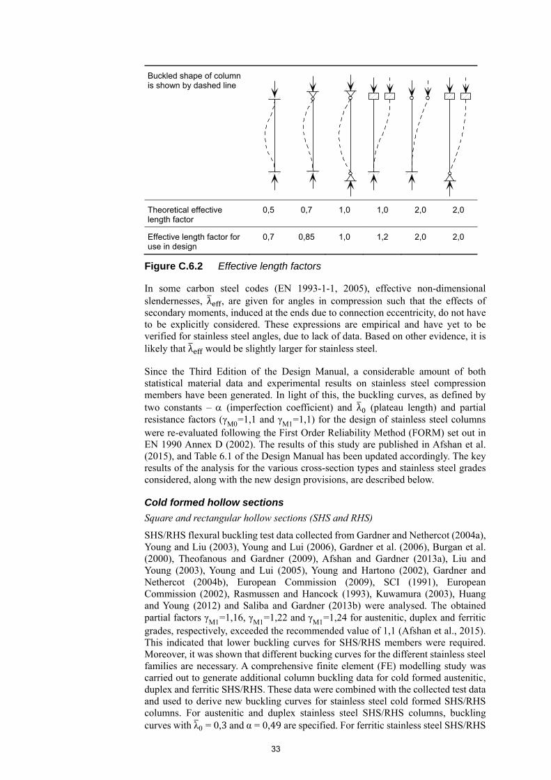
33
In some carbon steel codes (EN 1993-1-1, 2005), effective non-dimensional slendernesses, λ , are given for angles in compression such that the effects of secondary moments, induced at the ends due to connection eccentricity, do not have to be explicitly considered. These expressions are empirical and have yet to be verified for stainless steel angles, due to lack of data. Based on other evidence, it is likely that λ would be slightly larger for stainless steel.
Since the Third Edition of the Design Manual, a considerable amount of both statistical material data and experimental results on stainless steel compression members have been generated. In light of this, the buckling curves, as defined by two constants – (imperfection coefficient) and λ (plateau length) and partial resistance factors (γM0=1,1 and γM1=1,1) for the design of stainless steel columns were re-evaluated following the First Order Reliability Method (FORM) set out in EN 1990 Annex D (2002). The results of this study are published in Afshan et al. (2015), and Table 6.1 of the Design Manual has been updated accordingly. The key results of the analysis for the various cross-section types and stainless steel grades considered, along with the new design provisions, are described below.
Cold formed hollow sections
Square and rectangular hollow sections (SHS and RHS)
SHS/RHS flexural buckling test data collected from Gardner and Nethercot (2004a), Young and Liu (2003), Young and Lui (2006), Gardner et al. (2006), Burgan et al. (2000), Theofanous and Gardner (2009), Afshan and Gardner (2013a), Liu and Young (2003), Young and Lui (2005), Young and Hartono (2002), Gardner and Nethercot (2004b), European Commission (2009), SCI (1991), European Commission (2002), Rasmussen and Hancock (1993), Kuwamura (2003), Huang and Young (2012) and Saliba and Gardner (2013b) were analysed. The obtained partial factors γM1=1,16, γM1=1,22 and γM1=1,24 for austenitic, duplex and ferritic grades, respectively, exceeded the recommended value of 1,1 (Afshan et al., 2015). This indicated that lower buckling curves for SHS/RHS members were required. Moreover, it was shown that different bucking curves for the different stainless steel families are necessary. A comprehensive finite element (FE) modelling study was carried out to generate additional column buckling data for cold formed austenitic, duplex and ferritic SHS/RHS. These data were combined with the collected test data and used to derive new buckling curves for stainless steel cold formed SHS/RHS columns. For austenitic and duplex stainless steel SHS/RHS columns, buckling curves with λ0 = 0,3 and α = 0,49 are specified. For ferritic stainless steel SHS/RHS
Buckled shape of column is shown by dashed line
Theoretical effective length factor
0,5 0,7 1,0 1,0 2,0 2,0
Effective length factor for use in design
0,7 0,85 1,0 1,2 2,0 2,0
Figure C.6.2 Effective length factors
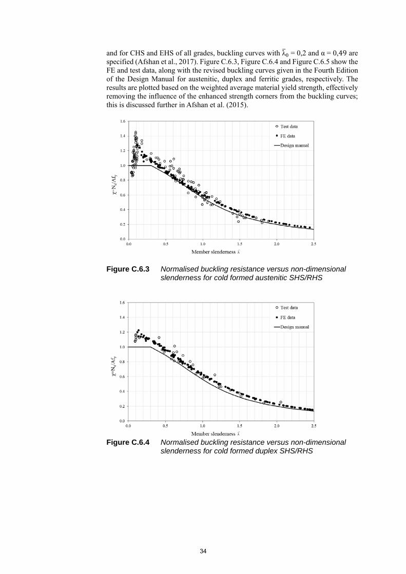
34
and for CHS and EHS of all grades, buckling curves with λ0 = 0,2 and α = 0,49 are specified (Afshan et al., 2017). Figure C.6.3, Figure C.6.4 and Figure C.6.5 show the FE and test data, along with the revised buckling curves given in the Fourth Edition of the Design Manual for austenitic, duplex and ferritic grades, respectively. The results are plotted based on the weighted average material yield strength, effectively removing the influence of the enhanced strength corners from the buckling curves; this is discussed further in Afshan et al. (2015).
Figure C.6.3 Normalised buckling resistance versus non-dimensional slenderness for cold formed austenitic SHS/RHS
Figure C.6.4 Normalised buckling resistance versus non-dimensional
slenderness for cold formed duplex SHS/RHS
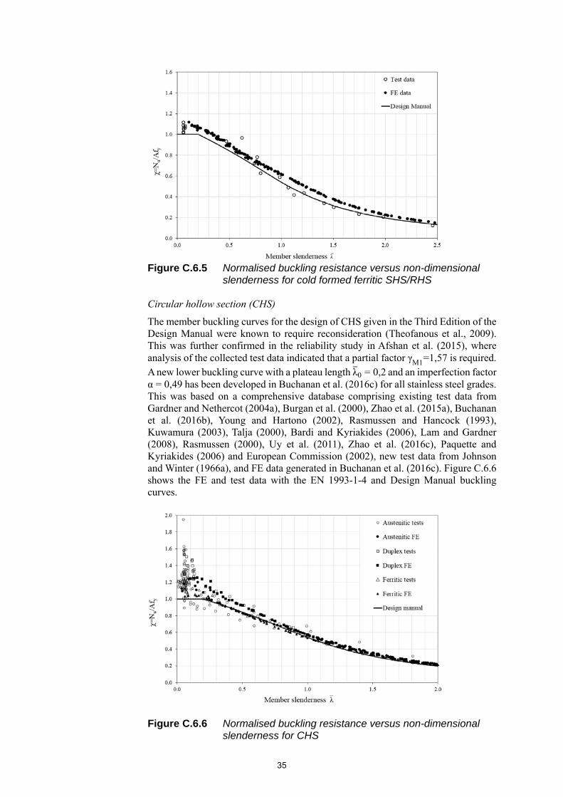
35
Figure C.6.5 Normalised buckling resistance versus non-dimensional
slenderness for cold formed ferritic SHS/RHS
Circular hollow section (CHS)
The member buckling curves for the design of CHS given in the Third Edition of the Design Manual were known to require reconsideration (Theofanous et al., 2009). This was further confirmed in the reliability study in Afshan et al. (2015), where analysis of the collected test data indicated that a partial factor γM1=1,57 is required. A new lower buckling curve with a plateau length λ0 = 0,2 and an imperfection factor α = 0,49 has been developed in Buchanan et al. (2016c) for all stainless steel grades. This was based on a comprehensive database comprising existing test data from Gardner and Nethercot (2004a), Burgan et al. (2000), Zhao et al. (2015a), Buchanan et al. (2016b), Young and Hartono (2002), Rasmussen and Hancock (1993), Kuwamura (2003), Talja (2000), Bardi and Kyriakides (2006), Lam and Gardner (2008), Rasmussen (2000), Uy et al. (2011), Zhao et al. (2016c), Paquette and Kyriakides (2006) and European Commission (2002), new test data from Johnson and Winter (1966a), and FE data generated in Buchanan et al. (2016c). Figure C.6.6 shows the FE and test data with the EN 1993-1-4 and Design Manual buckling curves.
Figure C.6.6 Normalised buckling resistance versus non-dimensional slenderness for CHS
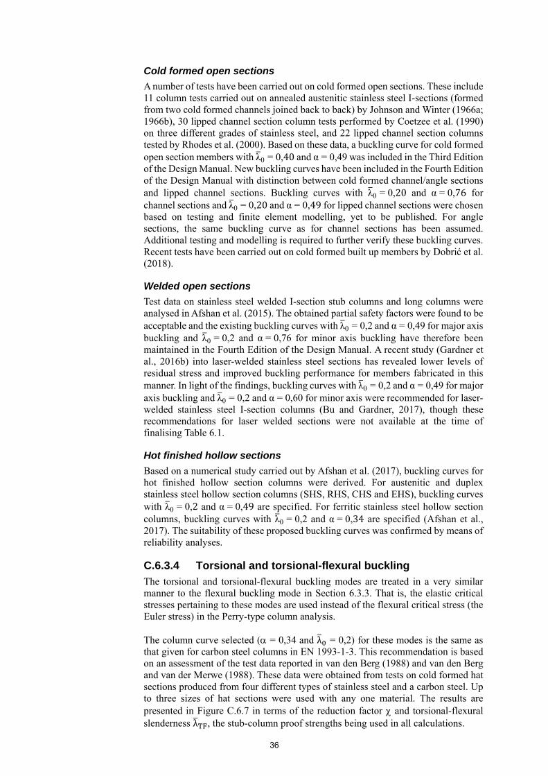
36
Cold formed open sections
A number of tests have been carried out on cold formed open sections. These include 11 column tests carried out on annealed austenitic stainless steel I-sections (formed from two cold formed channels joined back to back) by Johnson and Winter (1966a; 1966b), 30 lipped channel section column tests performed by Coetzee et al. (1990) on three different grades of stainless steel, and 22 lipped channel section columns tested by Rhodes et al. (2000). Based on these data, a buckling curve for cold formed open section members with λ0 = 0,40 and α = 0,49 was included in the Third Edition of the Design Manual. New buckling curves have been included in the Fourth Edition of the Design Manual with distinction between cold formed channel/angle sections and lipped channel sections. Buckling curves with λ0 = 0,20 and α = 0,76 for channel sections and λ0 = 0,20 and α = 0,49 for lipped channel sections were chosen based on testing and finite element modelling, yet to be published. For angle sections, the same buckling curve as for channel sections has been assumed. Additional testing and modelling is required to further verify these buckling curves. Recent tests have been carried out on cold formed built up members by Dobrić et al. (2018).
Welded open sections
Test data on stainless steel welded I-section stub columns and long columns were analysed in Afshan et al. (2015). The obtained partial safety factors were found to be acceptable and the existing buckling curves with λ0 = 0,2 and α = 0,49 for major axis buckling and λ0 = 0,2 and α = 0,76 for minor axis buckling have therefore been maintained in the Fourth Edition of the Design Manual. A recent study (Gardner et al., 2016b) into laser-welded stainless steel sections has revealed lower levels of residual stress and improved buckling performance for members fabricated in this manner. In light of the findings, buckling curves with λ0 = 0,2 and α = 0,49 for major axis buckling and λ0 = 0,2 and α = 0,60 for minor axis were recommended for laser-welded stainless steel I-section columns (Bu and Gardner, 2017), though these recommendations for laser welded sections were not available at the time of finalising Table 6.1.
Hot finished hollow sections
Based on a numerical study carried out by Afshan et al. (2017), buckling curves for hot finished hollow section columns were derived. For austenitic and duplex stainless steel hollow section columns (SHS, RHS, CHS and EHS), buckling curves with λ0 = 0,2 and α = 0,49 are specified. For ferritic stainless steel hollow section columns, buckling curves with λ0 = 0,2 and α = 0,34 are specified (Afshan et al., 2017). The suitability of these proposed buckling curves was confirmed by means of reliability analyses.
C.6.3.4 Torsional and torsional-flexural buckling
The torsional and torsional-flexural buckling modes are treated in a very similar manner to the flexural buckling mode in Section 6.3.3. That is, the elastic critical stresses pertaining to these modes are used instead of the flexural critical stress (the Euler stress) in the Perry-type column analysis.
The column curve selected ( = 0,34 and λ = 0,2) for these modes is the same as that given for carbon steel columns in EN 1993-1-3. This recommendation is based on an assessment of the test data reported in van den Berg (1988) and van den Berg and van der Merwe (1988). These data were obtained from tests on cold formed hat sections produced from four different types of stainless steel and a carbon steel. Up to three sizes of hat sections were used with any one material. The results are presented in Figure C.6.7 in terms of the reduction factor and torsional-flexural slenderness λ , the stub-column proof strengths being used in all calculations.
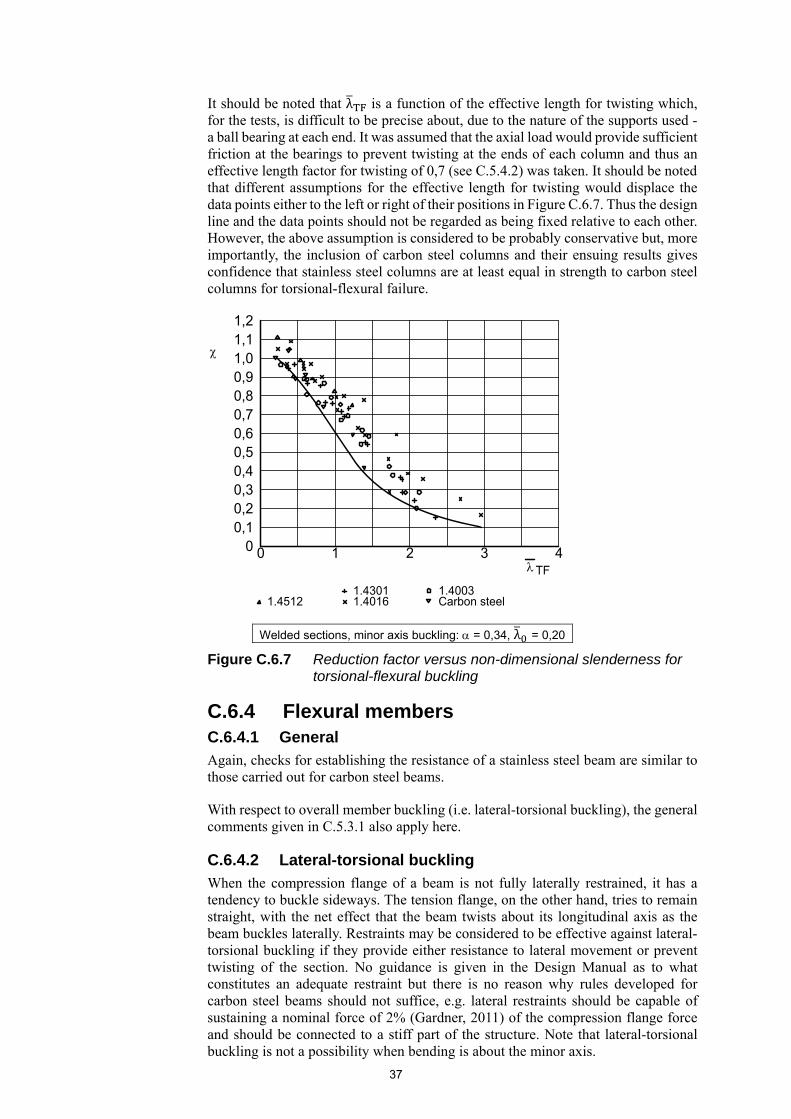
37
It should be noted that λ is a function of the effective length for twisting which, for the tests, is difficult to be precise about, due to the nature of the supports used - a ball bearing at each end. It was assumed that the axial load would provide sufficient friction at the bearings to prevent twisting at the ends of each column and thus an effective length factor for twisting of 0,7 (see C.5.4.2) was taken. It should be noted that different assumptions for the effective length for twisting would displace the data points either to the left or right of their positions in Figure C.6.7. Thus the design line and the data points should not be regarded as being fixed relative to each other. However, the above assumption is considered to be probably conservative but, more importantly, the inclusion of carbon steel columns and their ensuing results gives confidence that stainless steel columns are at least equal in strength to carbon steel columns for torsional-flexural failure.
C.6.4 Flexural members C.6.4.1 General
Again, checks for establishing the resistance of a stainless steel beam are similar to those carried out for carbon steel beams.
With respect to overall member buckling (i.e. lateral-torsional buckling), the general comments given in C.5.3.1 also apply here.
C.6.4.2 Lateral-torsional buckling
When the compression flange of a beam is not fully laterally restrained, it has a tendency to buckle sideways. The tension flange, on the other hand, tries to remain straight, with the net effect that the beam twists about its longitudinal axis as the beam buckles laterally. Restraints may be considered to be effective against lateral-torsional buckling if they provide either resistance to lateral movement or prevent twisting of the section. No guidance is given in the Design Manual as to what constitutes an adequate restraint but there is no reason why rules developed for carbon steel beams should not suffice, e.g. lateral restraints should be capable of sustaining a nominal force of 2% (Gardner, 2011) of the compression flange force and should be connected to a stiff part of the structure. Note that lateral-torsional buckling is not a possibility when bending is about the minor axis.
Welded sections, minor axis buckling: = 0,34, λ = 0,20
Figure C.6.7 Reduction factor versus non-dimensional slenderness for torsional-flexural buckling
0 40 1 2 3
TF
1,21,11,00,90,80,70,60,50,40,30,20,1
1.4301 1.4016 1.4512
1.4003 Carbon steel
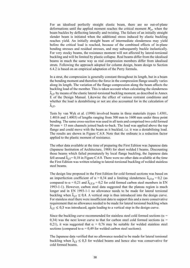
38
For an idealised perfectly straight elastic beam, there are no out-of-plane deformations until the applied moment reaches the critical moment when the beam buckles by deflecting laterally and twisting. The failure of an initially straight slender beam is initiated when the additional stress induced by elastic buckling reaches yield. An initially straight beam of intermediate slenderness may yield before the critical load is reached, because of the combined effects of in-plane bending stresses and residual stresses, and may subsequently buckle inelastically. For very stocky beams, the resistance moment will not affected by lateral-torsional buckling and will be limited by plastic collapse. Real beams differ from the idealised beams in much the same way as real compression members differ from idealised struts. Following the approach adopted for column design, beam design to Section 6.4.2 is based on an empirical adaptation of the Perry formula.
In a strut, the compression is generally constant throughout its length, but in a beam the bending moment and therefore the force in the compression flange usually varies along its length. The variation of the flange compression along the beam affects the buckling load of the member. This is taken account when calculating the slenderness λ by means of the elastic lateral-torsional buckling moment, as described in Annex E of the Design Manual. Likewise the effect of various restraint conditions and whether the load is destabilising or not are also accounted for in the calculation of λ .
Tests by van Wyk et al. (1990) involved beams in three materials (types 1.4301, 1.4016 and 1.4003) of lengths ranging from 300 mm to 1600 mm under three point bending. The same cross-section was used in all tests and comprised two cold formed 50 mm × 15 mm channels joined back-to-back. The load was applied above the top flange and could move with the beam as it buckled, i.e. it was a destabilising load. The results are shown in Figure C.6.8. Note that the ordinate is a reduction factor applied to the plastic moment of resistance.
The other data available at the time of preparing the First Edition was Japanese data (Japanese Institution of Architecture, 1988) for short welded I beams. Discounting those beams which failed prematurely by local flange buckling, the Japanese data fell around λ = 0,18 in Figure C.6.8. There were no other data available at the time the First Edition was written relating to lateral-torsional buckling of welded stainless steel beams.
The design line proposed in the First Edition for cold formed sections was based on an imperfection coefficient of = 0,34 and a limiting slenderness λ , = 0,2 (as compared to = 0,21 and λ , = 0,2 for cold formed carbon steel members in EN 1993-1-1). However, carbon steel data suggested that the plateau region is much longer and in EN 1993-1-1 no allowance needs to be made for lateral torsional buckling when λ 0,4. A vertical step is thus introduced into the design curve. For stainless steel there were insufficient data to support this and a more conservative requirement that no allowance needed to be made for lateral torsional buckling when λ 0,3 was introduced, again leading to a vertical step in the design curve.
Since the buckling curve recommended for stainless steel cold formed sections ( = 0,34) was the next lower curve to that for carbon steel cold formed sections ( = 0,21), it was suggested that = 0,76 may be suitable for welded stainless steel sections (compared to = 0,49 for welded carbon steel sections).
The Japanese data verified that no allowance needed to be made for lateral torsional buckling when λ 0,3 for welded beams and hence also was conservative for cold formed beams.
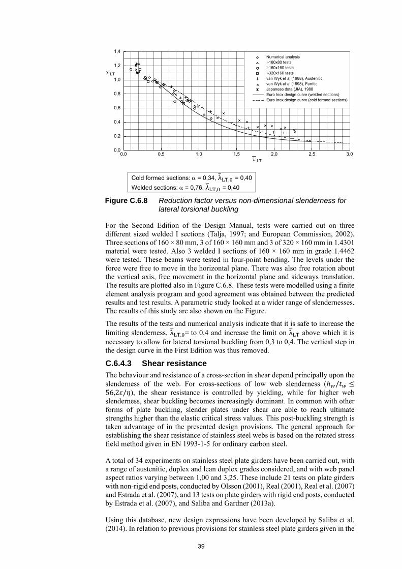
39
For the Second Edition of the Design Manual, tests were carried out on three different sized welded I sections (Talja, 1997; and European Commission, 2002). Three sections of 160 × 80 mm, 3 of 160 × 160 mm and 3 of 320 × 160 mm in 1.4301 material were tested. Also 3 welded I sections of 160 × 160 mm in grade 1.4462 were tested. These beams were tested in four-point bending. The levels under the force were free to move in the horizontal plane. There was also free rotation about the vertical axis, free movement in the horizontal plane and sideways translation. The results are plotted also in Figure C.6.8. These tests were modelled using a finite element analysis program and good agreement was obtained between the predicted results and test results. A parametric study looked at a wider range of slendernesses. The results of this study are also shown on the Figure.
The results of the tests and numerical analysis indicate that it is safe to increase the limiting slenderness, λ , = to 0,4 and increase the limit on λ above which it is necessary to allow for lateral torsional buckling from 0,3 to 0,4. The vertical step in the design curve in the First Edition was thus removed.
C.6.4.3 Shear resistance
The behaviour and resistance of a cross-section in shear depend principally upon the slenderness of the web. For cross-sections of low web slenderness ( /56,2 / ), the shear resistance is controlled by yielding, while for higher web slenderness, shear buckling becomes increasingly dominant. In common with other forms of plate buckling, slender plates under shear are able to reach ultimate strengths higher than the elastic critical stress values. This post-buckling strength is taken advantage of in the presented design provisions. The general approach for establishing the shear resistance of stainless steel webs is based on the rotated stress field method given in EN 1993-1-5 for ordinary carbon steel.
A total of 34 experiments on stainless steel plate girders have been carried out, with a range of austenitic, duplex and lean duplex grades considered, and with web panel aspect ratios varying between 1,00 and 3,25. These include 21 tests on plate girders with non-rigid end posts, conducted by Olsson (2001), Real (2001), Real et al. (2007) and Estrada et al. (2007), and 13 tests on plate girders with rigid end posts, conducted by Estrada et al. (2007), and Saliba and Gardner (2013a).
Using this database, new design expressions have been developed by Saliba et al. (2014). In relation to previous provisions for stainless steel plate girders given in the
Cold formed sections: = 0,34, λ , = 0,40
Welded sections: = 0,76, λ , = 0,40
Figure C.6.8 Reduction factor versus non-dimensional slenderness for lateral torsional buckling
LT
1,4
1,2
1,0
0,8
0,6
0,4
0,2
0,00,0 0,5 1,0 1,5 2,0 2,5 3,0
Numerical analysisI-160x80 testsI-160x160 testsI-320x160 testsvan Wyk et al (1988), Austeniticvan Wyk et al (1998), FerriticJapanese data (JIA), 1988Euro Inox design curve (welded sections)Euro Inox design curve (cold formed sections)
LT
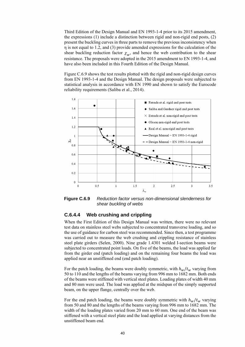
40
Third Edition of the Design Manual and EN 1993-1-4 prior to its 2015 amendment, the expressions (1) include a distinction between rigid and non-rigid end posts, (2) present the buckling curves in three parts to remove the previous inconsistency when η is not equal to 1.2, and (3) provide amended expressions for the calculation of the shear buckling reduction factor , and hence the web contribution to the shear resistance. The proposals were adopted in the 2015 amendment to EN 1993-1-4, and have also been included in this Fourth Edition of the Design Manual.
Figure C.6.9 shows the test results plotted with the rigid and non-rigid design curves from EN 1993-1-4 and the Design Manual. The design proposals were subjected to statistical analysis in accordance with EN 1990 and shown to satisfy the Eurocode reliability requirements (Saliba et al., 2014).
C.6.4.4 Web crushing and crippling
When the First Edition of this Design Manual was written, there were no relevant test data on stainless steel webs subjected to concentrated transverse loading, and so the use of guidance for carbon steel was recommended. Since then, a test programme was carried out to measure the web crushing and crippling resistance of stainless steel plate girders (Selen, 2000). Nine grade 1.4301 welded I-section beams were subjected to concentrated point loads. On five of the beams, the load was applied far from the girder end (patch loading) and on the remaining four beams the load was applied near an unstiffened end (end patch loading).
For the patch loading, the beams were doubly symmetric, with / varying from 50 to 110 and the lengths of the beams varying from 996 mm to 1682 mm. Both ends of the beams were stiffened with vertical steel plates. Loading plates of width 40 mm and 80 mm were used. The load was applied at the midspan of the simply supported beam, on the upper flange, centrally over the web.
For the end patch loading, the beams were doubly symmetric with / varying from 50 and 80 and the lengths of the beams varying from 996 mm to 1682 mm. The width of the loading plates varied from 20 mm to 60 mm. One end of the beam was stiffened with a vertical steel plate and the load applied at varying distances from the unstiffened beam end.
Figure C.6.9 Reduction factor versus non-dimensional slenderness for shear buckling of webs

41
The patch load tests were modelled using a finite element analysis program and good agreement with the test results was obtained. A parametric study was carried out to study the behaviour of a wider range of web slendernesses.
The test and numerical results were analysed and comparisons made with the guidance given in Eurocode 3. (The existing guidance given in EN 1993-1-4 refers simply to EN 1993-1-1.) The results indicated that the design procedure given in EN 1993-1-5 gives the best agreement between test and predicted values for both patch loading and end patch loading. In this model the characteristic resistance, is a function of the yield resistance , the elastic buckling load, and a resistance function . Figure C.6.10 shows the results of the tests, numerical analyses and the design curve. More recent work on web crippling in stainless steel sections has also been carried out (Bock et al., 2013; Bock and Real, 2014; Bock et al., 2015; Zhou and Young, 2013; Zhou and Young, 2008; Zahural Islam and Young, 2014).
C.6.4.5 Transverse stiffeners In essence, transverse stiffeners are to be treated as compression members requiring a check on cross-sectional resistance (bearing check) and buckling resistance. For intermediate stiffeners not subject to external loads, the axial loads are fed in gradually via shear in the web and the bearing check can be dispensed with.
The effective cross-section of the stiffener includes a proportion of web plate of up to 11 on either side of the stiffener flat. This effective width of web plate corresponds to the Class 3 limiting width for outstands in Table 5.4 of the Design Manual, i.e. the portion of web plate that can develop its proof load.
The buckling check is to be carried out according to Section 6.3.3 or Section 6.5.2 depending on whether symmetric stiffeners or asymmetric stiffeners are used. In the latter case an eccentricity moment of has to be allowed for, where is the axial force in the stiffener and is the distance of the centroid of the effective stiffener section from the mid thickness of the web.
The expression given for the force in an intermediate stiffener with no external loading is taken from EN 1993-1-5.
Figure C.6.10 Web crippling of stainless steel beams – test data and design curve
F /
Fu
y
1,00
0,80
0,60
0,40
1,20
0,000,00 0,50 1,00 1,50 2,00 2,50 3,00 3,50
1,20w
f
Numerical analysis - varying hNumerical analysis - varying tNumerical analysis - varying sNumerical analysis - varying aTestsNumerical analysis - testsENV 1993-1-5

42
The requirements given for the minimum second moment of area are to ensure that the stiffeners are sufficiently rigid to prevent web buckling. They are the same empirical expressions as those used in EN 1993-1-5 and other steel codes.
C.6.4.6 Determination of deflections
The accurate calculation of the deflections of members composed of stainless steel materials is a complex matter. The shape of the load-deflection curve is affected by the non-linear material stress-strain relationship (Timoshenko, 1956) and may be influenced by local buckling effects in the compression flange. Whereas in the case of carbon steel members the modulus is constant (i.e. equal to Young’s modulus) down the beam depth and along the length of the beam, for stainless steel members the (tangent) modulus may vary throughout the beam according to the value of stress at each point. An accurate deflection calculation will generally require the use of iterative techniques and this is unsuitable for design.
In the Design Manual an approximate method is given. It uses the secant moduli (see Figure C.6.11) corresponding to the stresses in the extreme fibres as a basis for estimating deflections. This approach has been shown (Johnson and Winter,1966b) to give adequate deflection estimates for design purposes. It should be borne in mind that deflection calculations can only provide estimates of the actual deflection that will occur in practice. Uncertainties in member restraint, element thicknesses, material behaviour (Annex C), let alone the loading, imply that it is unreasonable to expect or seek mathematical exactitude in estimating deflections.
It should be noted that beams may suffer some permanent deflection on removal of the load; this will be approximately (1 - Es/E) times the estimated total deflection
Calculating deflections by using a unique value of the secant modulus appropriate for the most highly stressed cross-section in the member leads to an over-estimation of deflections. The magnitude of the over-estimation depends on the distribution of the bending moment along the member; for example, the error is less significant for a beam with a uniform bending moment. A new methodology for calculating deflections in stainless steel beams, which takes fully into account the material non-linearity, has been proposed by Real and Mirambell (2005).
Inelastic deflections in stainless steel beams can be determined by a direct integration procedure, with adjustments for the boundary conditions, using the moment-curvature relationship for stainless steel cross-sections.
Figure C.6.11 Young’s, tangent and secant moduli
E E
1
E
1
1t
s
st
P
E = Modulus of elasticityE = tangent modulus at point PE = secant modulus at point P
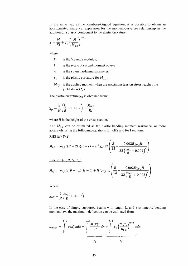
43
In the same way as the Ramberg-Osgood equation, it is possible to obtain an approximated analytical expression for the moment-curvature relationship as the addition of a plastic component to the elastic curvature.
χ,
where
is the Young’s modulus,
is the relevant second moment of area,
is the strain hardening parameter,
χ is the plastic curvature for , ,
, is the applied moment when the maximum tension stress reaches the yield stress ( ).
The plastic curvature χ is obtained from:
χ2
0,002 ,
where is the height of the cross-section.
And , can be estimated as the elastic bending moment resistance, or more accurately using the following equations for RHS and for I sections:
RHS ( )
, , 2 , 2 120,002 ,
32 , 0,002
I section ( , , ,
, , , 120,002 ,
32 , 0,002
Where
,2 , 0,002
In the case of simply supported beams with length L, and a symmetric bending moment law, the maximum deflection can be estimated from
/ /
.
/
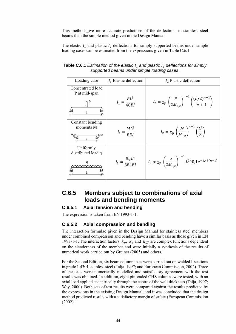
44
This method give more accurate predictions of the deflections in stainless steel beams than the simple method given in the Design Manual.
The elastic and plastic deflections for simply supported beams under simple loading cases can be estimated from the expressions given in Table C.6.1.
Table C.6.1 Estimation of the elastic and plastic deflections for simply supported beams under simple loading cases.
Loading case Elastic deflection Plastic deflection
Concentrated load P at mid-span
48 χ
2 ,
/21
Constant bending moments M
8 χ
, 8
Uniformly distributed load q
5384
χ 2 ,
0,1 ,
C.6.5 Members subject to combinations of axial loads and bending moments
C.6.5.1 Axial tension and bending
The expression is taken from EN 1993-1-1.
C.6.5.2 Axial compression and bending
The interaction formulae given in the Design Manual for stainless steel members under combined compression and bending have a similar basis as those given in EN 1993-1-1. The interaction factors , and are complex functions dependent on the slenderness of the member and were initially a synthesis of the results of numerical work carried out by Greiner (2005) and others.
For the Second Edition, six beam column tests were carried out on welded I-sections in grade 1.4301 stainless steel (Talja, 1997; and European Commission, 2002). Three of the tests were numerically modelled and satisfactory agreement with the test results was obtained. In addition, eight pin-ended CHS columns were tested, with an axial load applied eccentrically through the centre of the wall thickness (Talja, 1997; Way, 2000). Both sets of test results were compared against the results predicted by the expressions in the existing Design Manual, and it was concluded that the design method predicted results with a satisfactory margin of safety (European Commission (2002).

45
For the Fourth Edition of the Design Manual, a substantial amount of additional experimental and numerical data has enabled the derivation of improved interaction factors for stainless steel hollow sections under combined loading. A total of 31 tests have been carried out on SHS and RHS beam-columns, with austenitic (Way, 2000), duplex (Huang and Young, 2014b; Lui et al., 2014) and ferritic (Zhao et al., 2016a) stainless steels grades considered. These experimental and numerical results were used to validate new design formulae (Zhao et al., 2016e), given in Section 6.5.2 of the Design Manual, for determining the interaction factors , as a function of non-dimensional member slenderness λ. The formulae feature three coefficients , , and that differ with stainless steel grade, as set out in Table 6.6. These new interaction factors provide accurate, consistent, and safe-sided predictions for the resistance of stainless steel SHS and RHS members under combined loading. Similar coefficients have been developed for CHS beam-columns based on experiments carried out by Zhao et al. (2016c) on austenitic CHS beam-columns, and Buchanan et al. (2016b) on ferritic CHS beam-columns, together with numerical simulations.

46
C.7 JOINT DESIGN
C.7.1 General recommendations C.7.1.1 Durability The designer should consider ways of preventing corrosion at all stages of connection design.
Corrosion problems are most likely to occur at connections, whether they are bolted or welded connections. This is due to a number of potential deleterious features at connections such as crevices, dissimilar metal contact, heat affected zones, etc. As always, corrosion only occurs if there is a source of moisture. Sections 3 and 11 of the Design Manual contain further information.
C.7.1.2 Design assumptions
The general recommendations given here are no different from those for carbon steel. Connections work, even where the assumed path is not actually realised, because of steel’s great ductility and hence the potential for stress redistribution. In this respect, stainless steel, and particularly austenitic grade, is superior to carbon steel. Nevertheless, the deformation capacity of the fastening elements should be considered; it is not generally safe to share the load in a connection between different types of fasteners. For example, in a hybrid connection, fillet welds could fail before bolts in shear have taken up the clearances in the bolt holes.
C.7.1.3 Intersection and splices
Reducing bending moments at intersections and splices by avoiding eccentricities reflects good engineering practice.
At mid-height, the extreme fibres of a column are fully stressed (to ) at the ultimate limit state, even for a slender column (the reduction in strength due to column slenderness is matched by the stress due to the moment arising from strut action). Thus, any splice at mid-height has to be designed for forces and moments corresponding to the full design resistance.
C.7.1.4 Other general considerations
Although standardised details can be advantageous for carbon steelwork, the greater material cost of stainless steel favours a move away from uniformity of details to reduce such costs, even if increased labour charges result.
Again, the designer should be aware of the requirements of fabrication as given in Section 11. Control of welding distortion in particular should be noted, see Section 11.6.4.
C.7.2 Bolted connections C.7.2.1 General A variety of stainless steel fasteners is available, including bolts, rivets and self-tapping screws. The recommendations apply to bolts or set screws with washers under both the bolt head and the nut. Because of the soft surface of annealed austenitic stainless steel grades, hardened washers may be necessary to prevent any tendency to dig into the plate surface.
47
Stainless steel members will be connected to each other with bolted connections having similar geometric forms to those used in carbon steel structures. This being so, and with the expected broad similarity between stainless steel and carbon steel connection behaviour, the recommendations have been developed by verifying through testing the existing rules for carbon steel as set out in EN 1993-1-8. New provisions are introduced to limit bearing deformations.
C.7.2.2 Preloaded bolts
Slip-resistant connections are required, when deformations in bolted connections must be limited to pre-defined values either for serviceability or ultimate limit reasons. Typical applications can be found in bridges, cranes, radio masts and towers of wind turbines, which are loaded by alternate loading and/or fatigue or where functional requirements make slip-resistant connections necessary. Essential characteristics of these connections are firstly, the level of preload in the bolts and secondly, the slip factor which is mainly influenced by the surface roughness of the clamped plates and – again – by the level of preload. For this reason, the level of preload has to be guaranteed over the whole service life of the structure and loss of preloading due to relaxation and creep effects either because of e.g. geometrical tolerances of the clamped plates, creep due to plastic deformation of applied coatings or creep and relaxation of the structural elements themselves has to be sure avoided. Whereas slip-resistant connections are already used for carbon steel connections for several decades albeit with high costs, no design and execution rules exist for preloading of stainless steel bolts and subsequently, no slip factors are defined in standards. The European Commission funded project SIROCO studied the performance of stainless steel preloaded bolts experimentally and numerically. The final recommendations will be published towards the end of 2018 (European Commission, 2018). Findings of the project have been published by Afzali et al. (2017), Stranghöner et al. (2017a), Stranghöner et al. (2017b) and Hradil et al. (2017)
Note also that welding the nut to the bolt to prevent the former from unscrewing is a practice to be avoided.
C.7.2.3 Connected parts
Holes
The standard hole sizes are in common with carbon steel values. For holes with greater clearances or for slotted holes, there are no data yet available for stainless steel and specific testing would have to be carried out.
Position of holes
The minimum criteria for pitch, end and edge distance are given for the following reasons:
To give sufficient clearance for tightening bolts.
To limit any adverse interaction between high bearing stresses on neighbouring bolts.
To eliminate any tendency for bursting or in-plane deformation during drilling or punching; this reason particularly relates to minimum edge distance criteria.
To provide adequate resistance to tear-out of the bolts.
These reasons are common to carbon steelwork (Owens and Cheal, 1989). The minimum spacings have been aligned with those for carbon steel in EN 1993-1-8 for the Third Edition of the Design Manual.
Maximum criteria are set for carbon steelwork to eliminate local buckling of the plies and to ensure that a continuous paint film is maintained across the plies, thus
48
preventing corrosion at the interface. For stainless steel, the latter reason does not really apply and therefore the criteria in the Design Manual may be relaxed.
The position of holes is expressed in terms of the bolt hole diameter, rather than the bolt diameter, , in accordance with EN 1993-1-8.
Bearing resistance
The bearing resistance of bolted connections should be determined either on the basis of a strength or a deformation criterion. The design formulae for bolted connections failing by bearing adopted in the Fourth Edition of the Design Manual were proposed by Salih et al. (2011) on the basis of numerical analysis. The investigated parameters in the numerical studies included the end distance , the edge distance , the thickness of the connected plates and the connection type (i.e. single shear and double shear connections). Two additional phenomena - curling and pulling into line, associated with the bearing behaviour of thin plate connections, were also studied by Salih et al. (2011).
For bolted connections where deformation is not a key design consideration, the design formula was proposed based on the FE ultimate bearing resistance taken as the maximum attained load regardless of the associated deformation (i.e. similar to the treatment for net section failure). With regards to bolted connections where deformation is a design consideration, the design expression was developed on the basis of the FE ultimate bearing resistance taken as the load at a pre-specified acceptable deformation, with an adopted value of 1 mm under serviceability conditions for stainless steel connections.
The accuracy of the design formulae, as well as the design expressions adopted in EN 1993-1-4 was assessed through comparisons against the test results reported by Cai and Young (2014a), as shown in Table C.7.1. The comparisons are made based on the measured material and geometric properties from the test specimens, and with all partial factors set equal to unity. The design formulae employed in the Design Manual were shown to yield much more accurate and consistent bearing resistance predictions of bolted connections (as found in the numerical study of Salih et al. (2011), with the mean test to predicted resistance ratio , / , equal to 1,14 and a COV of 0,09, compared to EN 1993-1-4, which resulted in a mean test to
predicted resistance ratio ,
,equal to 1,65 and a COV of 0,18.

49
Table C.7.1 Comparisons of test results (Cai and Young, 2014a) of stainless steel bolted connections failing by plate bearing against the predicted resistances
Specimen ID Plate Material
Test resistance Nu,test (kN)
Nu,test/Nu,DM Nu,test/Nu,EC3
A-S-1-10 Austenitic 29,5 1,14 2,09
A-S-1-12 Austenitic 34,9 1,18 2,02
T-S-1-12 Austenitic 31,8 1,21 1,96
L-S-1-10 Duplex 29,9 0,99 1,66
L-S-1-12 Duplex 37,1 1,10 1,69
A-S-2Pe-8 Austenitic 41,8 0,99 1,82
A-S-2Pe-8-R Austenitic 41,6 1,00 1,85
T-S-2Pe-8 Austenitic 38,7 1,04 1,83
A-D-1-12 Austenitic 38,5 1,24 1,36
T-D-1-12 Austenitic 35,3 1,23 1,32
T-D-1-12-R Austenitic 33,3 1,17 1,24
L-D-1-12 Duplex 45,0 1,25 1,29
L-D-1-12-R Duplex 47,1 1,29 1,36
Mean 1,14 1,65
COV 0,09 0,18
Tension resistance
The resistance of tension members with bolted connections is equal to the lesser of the plastic resistance of the gross cross-section and the ultimate resistance of the net section at holes for fasteners. The design expression for the net section ultimate resistance of the connected plates is based on the numerical study conducted by Salih et al. (2010). In order to investigate the effect of the key parameters (the edge distance and the ratio between the number of bolts at the cross-section considered to the total number of bolts in the connection) on the net section resistance of lap connections, Salih et al. (2010) adopted six different connection configurations in the numerical study, which led to a range of ratios (0,5, 0,33, 0,25 and 0,4) and edge distance to bolt diameter ratios between 1,2 and 4,0.
The following design formula is given in EN 1993-1-4:
, γ where 1 3 0,3 1,0
However, the design expression in the Design Manual shows that the material ultimate tensile stress can be directly used as the failure stress without including a reduction factor . The accuracy of the design expression for net section tension resistance of bolted connections, given in the Design Manual and EN 1993-1-4, is assessed through comparisons against the test results reported by Cai and Young (2014a) and Ryan (1999), as shown in Table C.7.2. The comparison results indicate that the Design Manual formula yields a fairly high level of design accuracy and consistency in predicting the net section tension resistance of bolted connections, with the mean test to predicted resistance ratio equal to 1,06 and a COV of 0,05, which is an improvement over the EN 1993-1-4 provisions.
Angles connected by one leg and other unsymmetrically connected members in tension
The design expression for the net section resistance of angles connected to gusset plates in the Fourth Edition of the Design Manual was numerically derived by Salih

50
et al. (2013). A series of key parameters, including the number of bolts, the spacing between the bolts in the direction of loading, the length of the connection and the eccentricity of the connection, were varied in the numerical analysis, in order to investigate their influence on the net section resistance of bolted gusset plate connections. It was concluded by Salih et al. (2013) that the connection eccentricity and the overall connection length rather than the spacing between the bolts affect the tension behaviour of the angles in the bolted gusset plate connections.
Table C.7.2 Comparisons of test results (Cai and Young, 2014a; Ryan, 1999) of stainless steel bolted connections susceptible to net section tension failure against the predicted resistances
Test series Specimen ID Plate
Material
Test resistance Nu,test (kN)
Nu,test/Nu,DM Nu,test/Nu,EC3
Cai and Young
(2014a)
A-D-2Pe-8 Austenitic 32,5 1,02 1,02
T-D-2Pe-8 Austenitic 30,7 1,00 1,00
L-D-2Pe-8 Austenitic 40,7 1,06 1,06
L-D-2Pe-8-R Duplex 40,9 1,06 1,06
A-D-3-8 Austenitic 33,4 1,04 1,04
T-D-3-8 Austenitic 31,8 1,04 1,04
L-D-3-8 Duplex 42,8 1,13 1,13
L-D-3-8-R Duplex 42,6 1,11 1,11
A-D-4-6 Austenitic 38,7 1,13 1,22
A-D-4-6-R Austenitic 39,5 1,15 1,24
T-D-4-6 Austenitic 35,3 1,00 1,07
L-D-4-8 Duplex 44,3 1,17 1,17
Ryan (1999)
2 Austenitic 234,4 1,10 1,10
3 Austenitic 297,1 1,07 1,07
8 Austenitic 496,0 1,16 1,16
9 Austenitic 583,6 1,05 1,05
11 Austenitic 475,8 1,11 1,11
12 Austenitic 580,9 1,05 1,05
13 Ferritic 121,0 1,00 1,00
14 Ferritic 144,2 1,00 1,00
15 Ferritic 187,2 1,00 1,00
19 Ferritic 251,0 1,04 1,04
20 Ferritic 301,6 1,05 1,05
21 Ferritic 378,3 1,01 1,01
22 Ferritic 254,4 1,05 1,05
23 Ferritic 304,0 1,05 1,05
24 Ferritic 378,7 1,01 1,01
Mean 1,06 1,07
COV 0,05 0,06
C.7.2.4 Fasteners
Net areas
The tensile stress areas for stainless steel bolts to EN ISO 3506 (2009) are set out in Table C.7.3.

51
Table C.7.3 Tensile stress area for bolts to EN ISO 3506
Thread Size (Coarse Series) Stress Area, As (mm2)
M6 20,1
M8 36,6
M10 58,0
M12 84,3
M16 157,0
M20 245,0
M24 353,0
M30 561,0
M36 817,0
Shear, tension and shear/tension resistance
The recommendations given in these sections are all similar to rules given in EN 1993-1-8 for common structural bolts.
A limited test programme on the strength of stainless steel bolts was conducted to generate information for the First Edition of the Design Manual (SCI, 1990). The number and type of tests are set out in Table C.7.4 and the results are summarised in Figure C.7.1.
Table C.7.4 Number of tests on stainless steel bolts
Fastener (set screws)
Key to Fig C.6.7
Supplier
A B C
T S T/S T S T/S T S T/S
M20, A4-80 8 8 8 5 5 5 8 3 2
M16, A4-80 8 7 5 5 2
M16, A4-70 6 2
Notes:
T = Tension test, S = double shear test
T/S = Combined tension and shear

52
The lines of Figure C.7.1 correspond to the interaction formula given in Section 7.2.4 but using the specified tensile resistance (EN ISO 3506, 2009) for the ordinate and 0,6 times that for the abscissa. (The provision in Section 7.2.4 applies a 0,9 scaling factor to the ordinate.)
Given any particular batch and test type, the results were remarkably consistent, typically within ± 2 kN for tension and ± 5 kN for shear about the respective averages. Tests at loading rates differing by an order of magnitude showed little effect on failure loads.
In one instance (supplier C of M20 A4-80 set screws), the measured tensile capacity is less than the minimum specified level. Nevertheless, even this batch was satisfactory in pure shear and in combined tension and shear (for the ratio tested, T = S).
Ryan (1999) carried out tension and shear tests on individual bolt/nut assemblies. Some of the shear tests were carried out with the plates loaded in tension, and some in compression. Bolt diameters M12, M16 and M20 were tested; all the bolts were austenitic A4 property class 80 to EN ISO 3506. The results of the bolt tension and shear tests showed good agreement with the predicted values.
Long joints and large grip lengths
The shear flow in long joints is such that the fasteners at each end take more shear than the average shear of all the fasteners. Since stainless steel is more ductile than carbon steel, and hence permits a greater degree of force redistribution, stainless steel long joints should be at least of equal performance to those in carbon steel.
Likewise, there is no reason to think stainless steel bolts with large grip lengths behave any worse than normal structural bolts.
Figure C.7.1 Results of tests on stainless steel bolts
15050 100
Symbol* Fastener
M20, A4-80M16, A4-80M16, A4-70
*Letter indicates supplier
AB
C
BC
C
C
AB
A
C B A C B A
M20, A
4-80
M16, A
4-80
M16, A
4-70
200
150
100
50
0
Ten
sile
res
ista
nce
(kN
)
Shear resistance (kN)
53
C.7.3 Mechanical fasteners for thin gauge material
In general, the guidance in EN 1993-1-3 has been shown to be applicable to annealed and cold worked stainless steel (European Commission, 2006).
C.7.4 Welded connections The Design Manual adopts the approach for determining the strength of a fillet weld for carbon steel given in EN 1993-1-8. Additionally, recommendations are given against the use of intermittent welds and partial penetration butt welds in certain circumstances, to reduce the potential for corrosion.
The provisions are primarily intended for sheet and plate of 4 mm thickness and over.
It is important that good quality welds are made using verified procedures, see Section 11.6, for the provisions to be realised.
Tests by SCI for the First Edition of the Design Manual
Since there were no available data on welded joints in the relevant grades of stainless steel when the First Edition of the Design Manual was being written, a limited test programme was conducted (SCI, 1990). The fifteen specimens included a variety of different types of joints as shown in Table C.7.5.
Only full penetration butt weld tests were carried out on grades 1.4307 and 1.4404 material. Welds in duplex 1.4462 material were tested in all configurations. All specimens were prepared individually, without using run-off tabs, so that starting and finishing defects would be present. The results generally confirm the assertion that the strength of a weld may be considered as equal to the parent material. The lowest ratio of measured failure load to predicted failure load is 0,91 for specimen 7. Some of this discrepancy may be attributed to strain rate effects, as some specimens that failed away from the weld only reached a ratio of 0,95.
Tests on grade 1.4310 and ferritic stainless steels
Errera et al. (1970; 1974) and van der Merwe (1987) contain results of weld test programmes. Errera et al. (1970; 1974) report on a test programme on ¼ hard and ½ hard 1.4310 stainless steel and van der Merwe (1987) reports on ferritic stainless steels. The tests on the 1.4310 material show that the welding process has a partial annealing effect on the cold worked stainless steel with a consequent reduction in the cold worked strength.
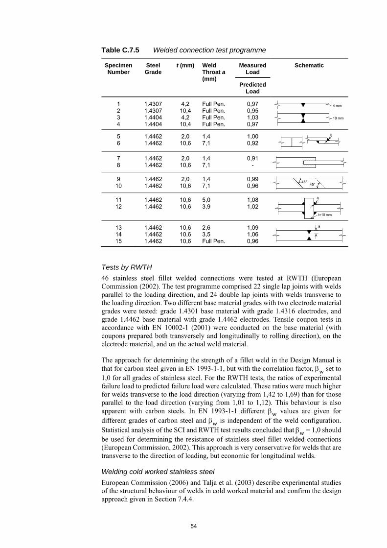
54
Table C.7.5 Welded connection test programme
Specimen Number
Steel Grade
t (mm) Weld Throat a (mm)
Measured Load
Schematic
Predicted Load
1 2 3 4
1.4307 1.4307 1.4404 1.4404
4,2 10,4 4,2
10,4
Full Pen. Full Pen. Full Pen. Full Pen.
0,97 0,95 1,03 0,97
5 6
1.4462 1.4462
2,0 10,6
1,4 7,1
1,00 0,92
7 8
1.4462 1.4462
2,0 10,6
1,4 7,1
0,91 -
9 10
1.4462 1.4462
2,0 10,6
1,4 7,1
0,99 0,96
11 12
1.4462 1.4462
10,6 10,6
5,0 3,9
1,08 1,02
13 14 15
1.4462 1.4462 1.4462
10,6 10,6 10,6
2,6 3,5 Full Pen.
1,09 1,06 0,96
Tests by RWTH
46 stainless steel fillet welded connections were tested at RWTH (European Commission (2002). The test programme comprised 22 single lap joints with welds parallel to the loading direction, and 24 double lap joints with welds transverse to the loading direction. Two different base material grades with two electrode material grades were tested: grade 1.4301 base material with grade 1.4316 electrodes, and grade 1.4462 base material with grade 1.4462 electrodes. Tensile coupon tests in accordance with EN 10002-1 (2001) were conducted on the base material (with coupons prepared both transversely and longitudinally to rolling direction), on the electrode material, and on the actual weld material.
The approach for determining the strength of a fillet weld in the Design Manual is that for carbon steel given in EN 1993-1-1, but with the correlation factor, set to 1,0 for all grades of stainless steel. For the RWTH tests, the ratios of experimental failure load to predicted failure load were calculated. These ratios were much higher for welds transverse to the load direction (varying from 1,42 to 1,69) than for those parallel to the load direction (varying from 1,01 to 1,12). This behaviour is also apparent with carbon steels. In EN 1993-1-1 different values are given for different grades of carbon steel and is independent of the weld configuration. Statistical analysis of the SCI and RWTH test results concluded that = 1,0 should be used for determining the resistance of stainless steel fillet welded connections (European Commission, 2002). This approach is very conservative for welds that are transverse to the direction of loading, but economic for longitudinal welds.
Welding cold worked stainless steel
European Commission (2006) and Talja et al. (2003) describe experimental studies of the structural behaviour of welds in cold worked material and confirm the design approach given in Section 7.4.4.
4 mm
10 mm
a
45°45°
a
t=10 mm
a
55
C.8 FIRE RESISTANT DESIGN
C.8.1 General Guidance in this Section follows that given in EN 1993-1-2 except where highlighted in Section C.8.3. Annex C of EN 1993-1-2 gives stainless steel properties at elevated temperatures. For the purposes of design, it is assumed that the actions are taken from EN 1991-1-2 (2005).
C.8.2 Mechanical properties at elevated temperatures
For the modelling and design of stainless steel structures in fire, it is necessary to consider the material properties at elevated temperatures. The key parameters are typically expressed as a proportion of the corresponding room temperature properties. Retention factors have been calculated based on testing by Ala-Outinen (1996), Ala-Outinen and Oksanen (1997), Sakumoto et al. (1996), European Commission (2002), European Commission (2009) and Outokumpu (2008). Whereas the Third Edition of the Design Manual included 7 sets of retention factors for 7 individual grades of austenitic and duplex stainless steel, following from the work by Gardner et al. (2010), the Fourth Edition now includes 7 sets of factors for 7 groups of stainless steel grades; three for austenitic stainless steels, two for duplex stainless steels and two for ferritic stainless steel. These sets group together grades with similar elevated temperature properties, with the tabulated retention factors derived based on the mean retentions factors for each group.
Retention factors for ultimate strain at elevated temperatures for the austenitic and duplex stainless steel grades have been derived based on the experimental data from Gardner et al. (2016a). The retention factors for all three austenitic groups have been taken as those stated for Austenitic I, which is expected to be conservative since the retention factors from other material properties are consistently lower for the Austenitic I group than the Austenitic II and III groups. The retention factors for ultimate strain for the two ferritic stainless steel groups have been calculated based on the ultimate strains given for Grade 1.4003 stainless steel in EN 1993-1-2.
Stainless steel exhibits a pronounced response to cold-work, and tests were carried out on cold formed stainless steel sections by Ala-Outinen (1996) and Chen and Young (2006) to evaluate the response at elevated temperatures. It was shown that the increased material strength existing at room temperature due to cold-work is constant up to about 700C, after which the beneficial effects begin to decrease and the influence of cold forming totally disappears at 900C. Considering the cold-work condition, where cold forming associated strength enhancements are utilised in design, the annealed 0,2% proof strength retention factors can be utilised up to temperatures of 700C and then must be reduced by 20% for temperatures of 800C and above. The tensile strength at elevated temperatures is less sensitive to the effects of cold-work and therefore the annealed retention factors may be used for all elevated temperatures (Gardner et al., 2010).
For structural fire design, the material strength at 2% total strain is employed for the design of some structural elements, reflecting the allowance for greater deformations and enabling the development of higher member strengths. The strength at 2% strain was previously presented as the 0,2% proof strength plus a proportion of the difference between the 0,2% proof strength and tensile strength. In the Fourth Edition of the Design Manual, retention factors for calculating the strength at 2%

56
strain are listed directly, and have been calculated based on the results from Gardner et al. (2010).
C.8.3 Determination of structural fire resistance The behaviour of unprotected stainless steel members was first studied by Ala-Outinen and Oksanen (1997). They tested six 40×40×4 mm RHS columns in grade 1.4301 stainless steel with a buckling length of approximately 890 mm. They also studied the behaviour of butt welded joints at elevated temperatures, concluding that the joints did not have an adverse effect on the behaviour of the member in fire. The behaviour of unprotected stainless steel beams and columns in fire was studied by Gardner and Baddoo (2006). Fire tests were carried out on six stainless steel columns and four stainless steel beams. All the members were grade 1.4301 stainless steel. Four of the columns were fixed and two were pinned. Three of the beams were simply supported and one was continuous over two spans. The fire tests on four of the columns and two of the beams were subsequently modelled using finite element analysis. Reasonably good agreement was obtained between the test results and numerical analysis. A parametric study analysed the effects of varying the overall slenderness of columns, the load ratio (the applied load divided by the room temperature resistance) and the cross-sectional slenderness.
Using the material properties for stainless steel previously derived (European Commission, 2000), design guidance for carbon steel in EN 1993-1-2 was shown to be applicable to stainless steel columns (cold formed open and hollow cross-sections only) and stainless steel beams supporting a concrete slab. Figure C.8.1 shows the column design curves against the results of the tests and numerical analyses. (A family of design curves is needed because the critical temperature is a function of both load ratio and non-dimensional slenderness, λ.) Figure C.8.2 shows the beam design curves against the results of the tests and numerical analyses.
Note: Values of given next to each test and FE point
Figure C.8.1 Test data, results of numerical analyses and design curve for stainless steel columns in fire
1200
1000
800
600
400
200
0
Crit
ical
tem
pera
ture
°C
Load ratio0,0 0,2 0,4 0,6 0,8 0,90,1 0,3 0,5 0,7
0,61
0,61
0,56 1,271,38
0,920,460,64
0,640,46
0,460,46
0,46
TestsNumerical analysisEuro Inox Design Curve = 0,5Euro Inox Design Curve = 0,8Euro Inox Design Curve = 1,2

57
However, for the column tested with a welded, open cross-section, this design approach was found to over-estimate the measured resistance and further work is necessary before definitive design recommendations can be made for stainless steel columns with this type of cross-section.
EN 1993-1-2 uses the strength at 2% total strain to determine the structural fire resistance for all modes of loading of steel members with Classes 1, 2 and 3 cross-sections. Fire tests on structural members indicate that the strain at failure is strongly dependent on the loading mode. For example, beams supporting concrete or composite floors experience very high strains at failure (>2%). Load tests on columns show they behave rather differently with low strains existing at failure, since failure is primarily controlled by instability, as triggered when a marked loss in stiffness occurs (i.e. in the region of the 0,2% proof stress). Therefore, the design strengths presented in Table C.8.1 have been adopted in the Design Manual.
Table C.8.1 Approach for fire resistant design
Member Strength and buckling curve for use in design
Columns p0,2, (all cross-section classes) and the appropriate room temperature buckling curve
Restrained beams , (class 1-3) and p0,2, (class 4)
Unrestrained beams p0,2, (all cross-section classes) and the appropriate room temperature lateral torsional buckling curve
Tension members , (all cross-section classes)
More recently, further elevated temperature testing on ferritic (Tondini et al., 2013) and austenitic (Fan et al., 2016a) stainless steel columns, as well as finite element modelling of ferritic (Afshan et al., 2016), austenitic (Fan et al. 2016b) and cold formed duplex (To and Young, 2008) stainless steel columns, has been carried out. Elevated temperature testing (Fan et al., 2016c) and finite element modelling (Fan et al., 2016d) has also been carried out on austenitic stainless steel beams. Material properties at elevated temperatures have been considered, with testing on cold formed duplex stainless steel by Huang and Young (2014a), and on duplex stainless steel by Chen and Young (2006). Elevated temperature tests have also been carried out on both single shear (Cai and Young 2014b) and double shear (Cai and Young,
Figure C.8.2 Test data, results of numerical analyses and design curve for stainless steel beams
1200
1000
800
600
400
200
0
Crit
ical
tem
pera
ture
°C
Load ratio
Continuous beam
TestsNumerical analysisEuro Inox design curve
0,0 0,2 0,4 0,6 0,8 1,0 1,2

58
2015) cold formed austenitic and duplex stainless steel connections, with a numerical investigation also carried out for the double shear connections (Cai and Young, 2016). Overall, the newly generated data support the provisions of the Design Manual.
Although there is no relevant test data, the Design Manual also gives guidance on the shear resistance, lateral torsional buckling resistance and resistance to combined axial compression and bending of stainless steel members in fire, based on the recommendations for carbon steel in EN 1991-1-2.
Section 8.4.4 of the Design Manual is the approach given for carbon steels in EN 1993-1-2 for determining the temperature development in structural sections in fire. The heating up characteristics of a range of stainless steel sections with section factors varying from around 200 m-1 to 700 m-1 were studied in a test programme (Gardner and Baddoo, 2006). Numerical modelling agreed well with the tests. Furthermore, it was shown that for a given section factor, a stainless steel section heats up at a very similar rate to a carbon steel section. Further studies were carried out by Gardner and Ng (2006) in which the recommendation was made that a value of 0,2 was more appropriate for the emissivity of stainless steel than the value of 0,4 given in EN 1993-1-2.
For advanced calculation methods, the guidance given in EN 1993-1-2 can be followed.
C.8.4 Thermal properties at elevated temperatures
The thermal properties of stainless steel differ to those of carbon steels due to the differences in microstructure and alloying content. The thermal properties of stainless steel are given in EN 1993-1-2. The Fourth Edition of the Design Manual also includes values for the mean coefficient of thermal expansion for austenitic, duplex and ferritic stainless steels and for the specific thermal capacity and thermal conductivity of ferritic steels provided by Outokumpu and www.stahldaten.de. A comparison of the thermal properties of stainless steels with those of carbon steels is given by Ala-Outinen (1996).
C.8.5 Material modelling at elevated temperatures
Stainless steel is characterised by a non-linear rounded stress-strain response with no sharply defined yield point. The two-stage Ramberg-Osgood material model, as presented in Annex C of the Fourth Edition of the Design Manual and adopted in EN 1993-1-4, accurately captures the stress-strain response of stainless steel at room temperature. For elevated temperatures, this same two-stage Ramberg-Osgood concept has been shown to be applicable for describing the stress-strain response, with suitable modifications for the elevated temperature properties (Gardner et al., 2010). The elevated temperature strength at 2% strain is available to structural engineers and is employed in a number of aspects of structural fire design; use is therefore made of the strength at 2% strain in the elevated temperature material model. In addition to the model employing the strength at 2% strain, an alternative model based on the ultimate strain, is also provided. They have both been shown to provide an accurate representation of stainless steel stress-strain responses at elevated temperatures, with the 2% strain model being slightly more precise at lower strains and the ultimate strain model being slightly more precise at higher strains (Gardner et al., 2016a).
Limited experimental data currently exist on the effect of elevated temperatures on the strain hardening exponents. From the work carried out by Gardner et al. (2010;
59
2016a), it has been concluded that the elevated temperature exponent may assume the corresponding room temperature values of , while for calculating the strain hardening exponents for the second stage of the model, and , , the room temperature expression for but with the elevated temperature values for p0,2, and
, , may be used.
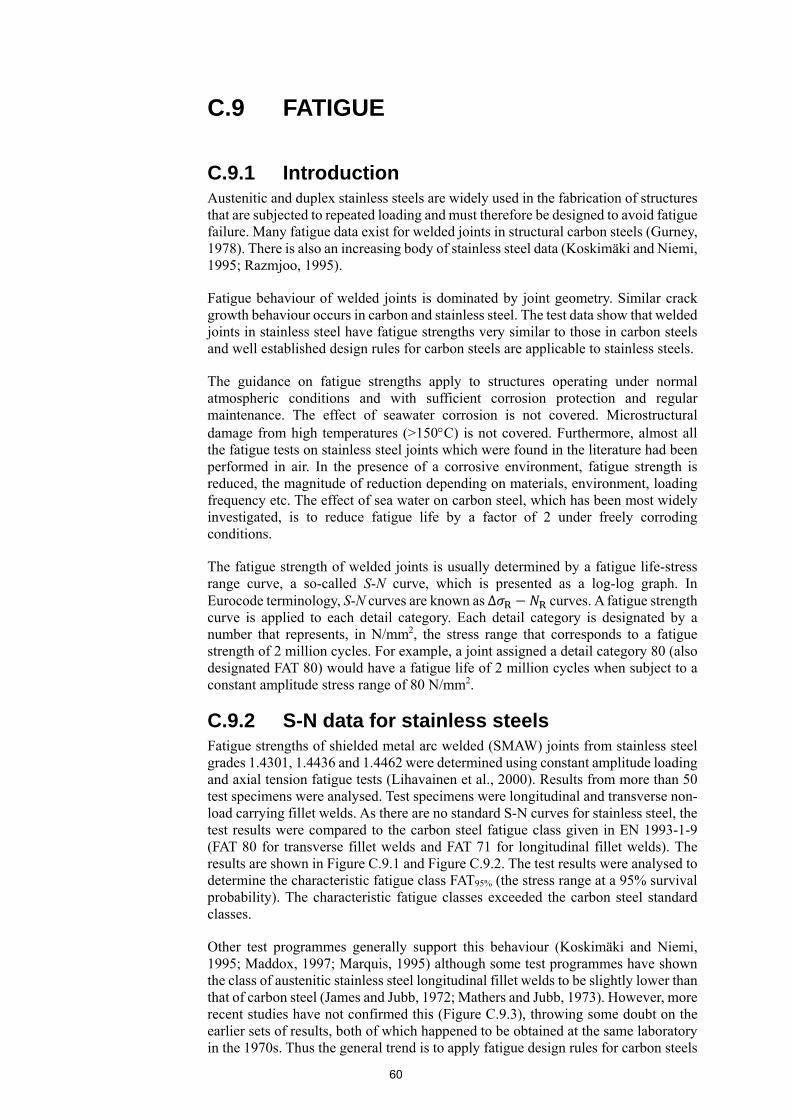
60
C.9 FATIGUE
C.9.1 Introduction Austenitic and duplex stainless steels are widely used in the fabrication of structures that are subjected to repeated loading and must therefore be designed to avoid fatigue failure. Many fatigue data exist for welded joints in structural carbon steels (Gurney, 1978). There is also an increasing body of stainless steel data (Koskimäki and Niemi, 1995; Razmjoo, 1995).
Fatigue behaviour of welded joints is dominated by joint geometry. Similar crack growth behaviour occurs in carbon and stainless steel. The test data show that welded joints in stainless steel have fatigue strengths very similar to those in carbon steels and well established design rules for carbon steels are applicable to stainless steels.
The guidance on fatigue strengths apply to structures operating under normal atmospheric conditions and with sufficient corrosion protection and regular maintenance. The effect of seawater corrosion is not covered. Microstructural damage from high temperatures (>150C) is not covered. Furthermore, almost all the fatigue tests on stainless steel joints which were found in the literature had been performed in air. In the presence of a corrosive environment, fatigue strength is reduced, the magnitude of reduction depending on materials, environment, loading frequency etc. The effect of sea water on carbon steel, which has been most widely investigated, is to reduce fatigue life by a factor of 2 under freely corroding conditions.
The fatigue strength of welded joints is usually determined by a fatigue life-stress range curve, a so-called S-N curve, which is presented as a log-log graph. In Eurocode terminology, S-N curves are known as Δ curves. A fatigue strength curve is applied to each detail category. Each detail category is designated by a number that represents, in N/mm2, the stress range that corresponds to a fatigue strength of 2 million cycles. For example, a joint assigned a detail category 80 (also designated FAT 80) would have a fatigue life of 2 million cycles when subject to a constant amplitude stress range of 80 N/mm2.
C.9.2 S-N data for stainless steels Fatigue strengths of shielded metal arc welded (SMAW) joints from stainless steel grades 1.4301, 1.4436 and 1.4462 were determined using constant amplitude loading and axial tension fatigue tests (Lihavainen et al., 2000). Results from more than 50 test specimens were analysed. Test specimens were longitudinal and transverse non-load carrying fillet welds. As there are no standard S-N curves for stainless steel, the test results were compared to the carbon steel fatigue class given in EN 1993-1-9 (FAT 80 for transverse fillet welds and FAT 71 for longitudinal fillet welds). The results are shown in Figure C.9.1 and Figure C.9.2. The test results were analysed to determine the characteristic fatigue class FAT95% (the stress range at a 95% survival probability). The characteristic fatigue classes exceeded the carbon steel standard classes.
Other test programmes generally support this behaviour (Koskimäki and Niemi, 1995; Maddox, 1997; Marquis, 1995) although some test programmes have shown the class of austenitic stainless steel longitudinal fillet welds to be slightly lower than that of carbon steel (James and Jubb, 1972; Mathers and Jubb, 1973). However, more recent studies have not confirmed this (Figure C.9.3), throwing some doubt on the earlier sets of results, both of which happened to be obtained at the same laboratory in the 1970s. Thus the general trend is to apply fatigue design rules for carbon steels
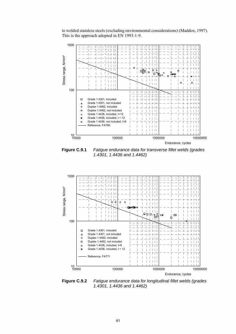
61
to welded stainless steels (excluding environmental considerations) (Maddox, 1997). This is the approach adopted in EN 1993-1-9.
Figure C.9.1 Fatigue endurance data for transverse fillet welds (grades 1.4301, 1.4436 and 1.4462)
Figure C.9.2 Fatigue endurance data for longitudinal fillet welds (grades 1.4301, 1.4436 and 1.4462)
1000
100
1010000 100000 1000000 10000000
Endurance, cycles
Str
ess
rang
e, N
/mm
²
Grade 1.4301, includedGrade 1.4301, not includedDuplex 1.4462, includedDuplex 1.4462, not includedGrade 1.4436, included, t=12Grade 1.4436, included, t = 12Grade 1.4436, not included, t=8Reference, FAT80
100
1010000 100000 1000000 10000000
Endurance, cycles
1000
Str
ess
rang
e, N
/mm
²
Grade 1.4301, includedGrade 1.4301, not includedDuplex 1.4462, includedDuplex 1.4462, not includedGrade 1.4436, included, t=8Grade 1.4436, included, t = 12
Reference, FAT71
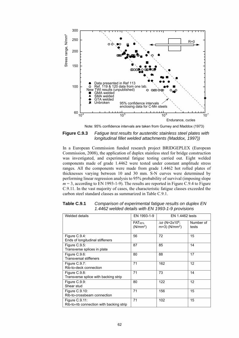
62
In a European Commission funded research project BRIDGEPLEX (European Commission, 2008), the application of duplex stainless steel for bridge construction was investigated, and experimental fatigue testing carried out. Eight welded components made of grade 1.4462 were tested under constant amplitude stress ranges. All the components were made from grade 1.4462 hot rolled plates of thicknesses varying between 10 and 30 mm. S-N curves were determined by performing linear regression analysis to 95% probability of survival (imposing slope m = 3, according to EN 1993-1-9). The results are reported in Figure C.9.4 to Figure C.9.11. In the vast majority of cases, the characteristic fatigue classes exceeded the carbon steel standard classes as summarized in Table C.9.1.
Table C.9.1 Comparison of experimental fatigue results on duplex EN 1.4462 welded details with EN 1993-1-9 provisions
Welded details EN 1993-1-9 EN 1.4462 tests
FAT95% (N/mm2)
∆σ (N=2x10⁶; m=3) (N/mm2)
Number of tests
Figure C.9.4: Ends of longitudinal stiffeners
56 72 15
Figure C.9.5: Transverse splices in plate
87 85 14
Figure C.9.6: Transversal stiffeners
80 88 17
Figure C.9.7: Rib-to-deck connection
71 162 12
Figure C.9.8: Transverse splice with backing strip
71 73 14
Figure C.9.9: Shear stud
80 122 12
Figure C.9.10: Rib-to-crossbeam connection
71 156 15
Figure C.9.11: Rib-to-rib connection with backing strip
71 102 15
Note: 95% confidence intervals are taken from Gurney and Maddox (1973)
Figure C.9.3 Fatigue test results for austenitic stainless steel plates with longitudinal fillet welded attachments (Maddox, 1997))
300
250
200
150
100
60104 10 10 105 6 7
R=0
Str
ess
rang
e, N
/mm
²
Endurance, cycles
95% confidence intervalsenclosing data for C-Mn steels
Data presented in Ref 113 Ref. 119 & 120 data from one lab.New TWI results (unpublished) GMA welded SMA welded GTA welded Unbroken

63
Figure C.9.4 Fatigue endurance data for ends of longitudinal stiffeners weld (grade 1.4462; SAW technique)
Figure C.9.5 Fatigue endurance data for transverse splices in plate (grade 1.4462; FCAW+SAW technique)
Figure C.9.6 Fatigue endurance data for transversal stiffeners (grade 1.4462; GMAW technique)

64
Figure C.9.7 Fatigue endurance data for rib-to-deck connection (grade 1.4462; SAW technique)
Figure C.9.8 Fatigue endurance data for transverse splice with backing strip (grade 1.4462; SAW technique)
Figure C.9.9 Fatigue endurance data for shear stud welded on base material (grade 1.4462; SW stud arc welding)

65
C.9.3 S-N data for cold worked stainless steels Fatigue tests on intermittent and continuous longitudinal load-carrying fillet welds on grade 1.4318 stainless steel cold worked to strength level C850 have been carried out (European Commission, 2006). The study concluded that the guidance in EN 1993-1-9 can safely be applied to cold worked stainless steel, in fact the resistance of the cold worked joints was considerably higher than the relevant Eurocode classifications.
C.9.4 Fatigue crack growth data for stainless steels
An alternative method, although less commonly used, for fatigue assessment is the fracture mechanics approach. It is based on the observed relationship between the range in the stress intensity factor, , and the rate of growth of fatigue cracks, / . This usually takes a sigmoidal form in a log versus log / plot.
Below a threshold stress intensity factor range, , no crack growth occurs. For
Figure C.9.10 Fatigue endurance data for rib-to-crossbeam connection (grade 1.4462; GMAW technique)
Figure C.9.11 Fatigue endurance data for rib-to-rib connection with backing strip (grade 1.4462; GMAW technique)
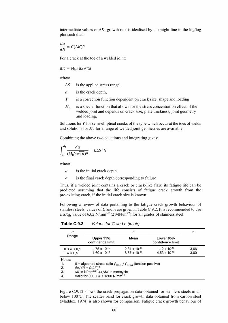
66
intermediate values of , growth rate is idealised by a straight line in the log/log plot such that:
Δ
For a crack at the toe of a welded joint:
Δ Δ √π
where
Δ is the applied stress range,
a is the crack depth,
Y is a correction function dependent on crack size, shape and loading
is a special function that allows for the stress concentration effect of the welded joint and depends on crack size, plate thickness, joint geometry and loading.
Solutions for for semi-elliptical cracks of the type which occur at the toes of welds and solutions for for a range of welded joint geometries are available.
Combining the above two equations and integrating gives:
√πΔ
where
is the initial crack depth
is the final crack depth corresponding to failure
Thus, if a welded joint contains a crack or crack-like flaw, its fatigue life can be predicted assuming that the life consists of fatigue crack growth from the pre-existing crack, if the initial crack size is known.
Following a review of data pertaining to the fatigue crack growth behaviour of stainless steels, values of and are given in Table C.9.2. It is recommended to use a value of 63,2 N/mm3/2 (2 MN/m3/2) for all grades of stainless steel.
Table C.9.2 Values for C and n (in air)
Range
Upper 95% confidence limit
Mean Lower 95% confidence limit
0 < 0,1 = 0,5
4,75 x 10⁻¹⁵ 1,60 x 10⁻¹⁴
2,31 x 10⁻¹⁵
8,57 x 10⁻¹⁵ 1,12 x 10⁻¹⁵
4,53 x 10⁻¹⁵ 3,66 3,60
Notes: 1. = algebraic stress ratio min / max (tension positive) 2. / = (Δ
3. Δ in N/mm3/2, / in mm/cycle 4. Valid for 300 1800 N/mm3/2
Figure C.9.12 shows the crack propagation data obtained for stainless steels in air below 100°C. The scatter band for crack growth data obtained from carbon steel (Maddox, 1974) is also shown for comparison. Fatigue crack growth behaviour of
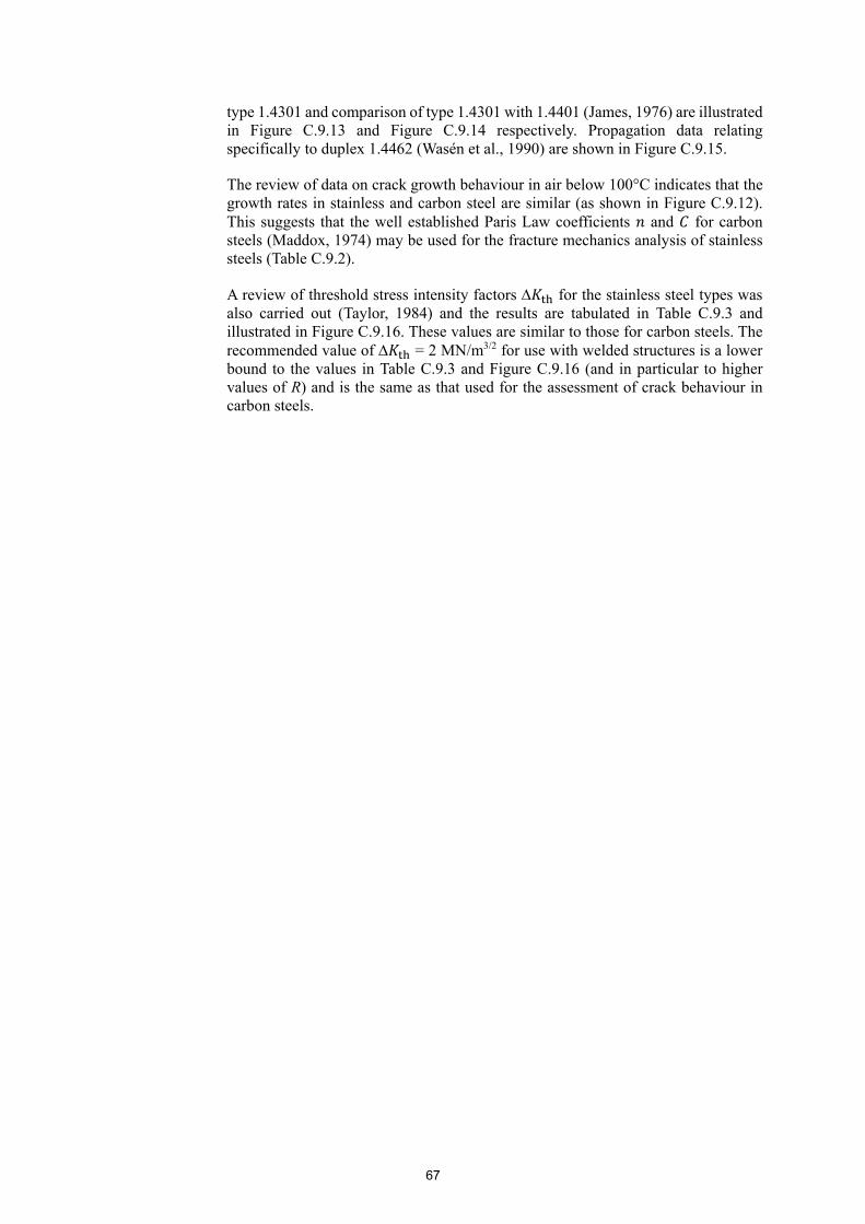
67
type 1.4301 and comparison of type 1.4301 with 1.4401 (James, 1976) are illustrated in Figure C.9.13 and Figure C.9.14 respectively. Propagation data relating specifically to duplex 1.4462 (Wasén et al., 1990) are shown in Figure C.9.15.
The review of data on crack growth behaviour in air below 100°C indicates that the growth rates in stainless and carbon steel are similar (as shown in Figure C.9.12). This suggests that the well established Paris Law coefficients and for carbon steels (Maddox, 1974) may be used for the fracture mechanics analysis of stainless steels (Table C.9.2).
A review of threshold stress intensity factors for the stainless steel types was also carried out (Taylor, 1984) and the results are tabulated in Table C.9.3 and illustrated in Figure C.9.16. These values are similar to those for carbon steels. The recommended value of = 2 MN/m3/2 for use with welded structures is a lower bound to the values in Table C.9.3 and Figure C.9.16 (and in particular to higher values of R) and is the same as that used for the assessment of crack behaviour in carbon steels.
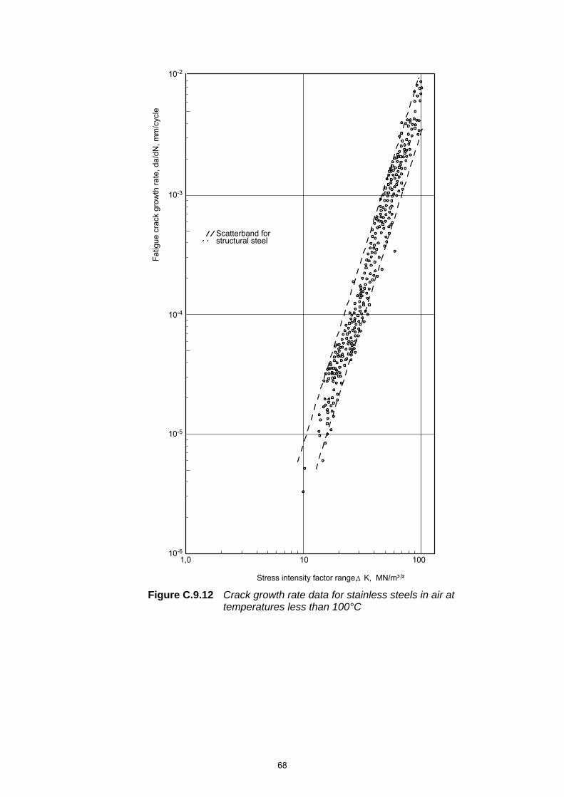
68
Figure C.9.12 Crack growth rate data for stainless steels in air at temperatures less than 100°C
10 100
10-2
Fat
igue
cra
ck g
row
th r
ate,
da/
dN, m
m/c
ycle
10-3
10-4
10-5
10-6
Scatterband forstructural steel
1,0
Stress intensity factor range, K, MN/m³ ²/
69
Figure C.9.13 Fatigue crack growth behaviour of stainless steel grade 1.4301 at room temperature
Figure C.9.14 Comparison of fatigue growth behaviour of austenitic stainless steels
Scatterband for structural steel
10-2
10
10
10
-3
-4
-5
10 1 10 2
Fat
igue
cra
ck g
row
th r
ate,
da/
dN, m
m/c
ycle
Stress intensity factor range, K, MN/m³ ²
Scatterband for annealedtype 1.4301 stainless steelat room temperature
Scatterband forstructural steel
10 1 10 2
10-2
Fat
igue
cra
ck g
row
th r
ate,
da/
dN, m
m/c
ycle
10-3
10-4
10-5
Stress intensity factor range, K, MN/m³ ²
Annealed type 1.4401 stainless steel,37°C, R - 0,04
Laboratory air environmentNaCl, CaCl, KCl solution
Annealed type 1.4301 stainless steel,25°C, R - 0
Dry air environmentHumid air environment
/

70
Figure C.9.15 Fatigue crack growth behaviour of duplex grade 1.4462
-8
-7
-6
10
10
10
10
10
10
Fat
igue
cra
ck g
row
th r
ate,
da/
dN, m
m/c
ycle
-3
-4
-5
(a)(b)(c)(d)
Hot rolledQuench annealedCold rolledCold rolled and annealed
Scatterband forstructural steel
a b c d
3 10 20 30
Stress intensity factor range, K, MN/m³ ² /

71
Table C.9.3 Fatigue threshold values for stainless steel in air at room temperature
Material Yield Strength (N/mm2)
Stress Ratio R
Kth (MN/m3/2)
1.4401 (18Cr, 12Ni) 268 0,08 0,1 0,2
0,38 0,5
5,2 5,0 4,3 3,2 3,3
1.4401, as previous; aged 292 0,12 0,33 0,55 0,68
3,7 3,4 2,7 2,7
1.4401 (18Cr, 12Ni) 255 0,05 0,05 0,2
0,35 0,6
6,8 6,1 5,3 4,5 3,0
1.4401 (18Cr, 12Ni) 198 0,02 0,2
0,33 0,35 0,61
8,1 6,9 6,2 5,9 3,8
1.4301 (18,5Cr, 8,8Ni) 222 0,0 0,5 0,8 0,9
5,5 3,1 2,9 2,3
1.4301 (20,2Cr, 8,5Ni) 265 0,0 0,4 0,8
3,5 3,5 4,0
1.4301 (19,2Cr, 10,3Ni) 221 0,0 0,17 0,37 0,80
5,6 4,5 4,2 2,8
Figure C.9.16 Variation of threshold stress intensity factor range with stress ratio for stainless steels in air
00
1
2
3
4
5
6
7
8
9
10
12
11
Stress ratio, R
0,1 0,2 0,3 0,4 0,5 0,6 0,7 0,8 0,9 1,0
/
Thr
eshh
old
stre
ss in
tens
ity fa
ctor
ran
ge,
K
MN
/m³
²th

72
C.10 TESTING
The guidance given in the Design Manual has been formulated with the benefit of experience gained in various test programmes that supplied background data for the four Editions of the Design Manual.
73
C.11 FABRICATION ASPECTS
C.11.1 Introduction A broad overview of the precautions to be observed during fabrication is given in the Design Manual. It is emphasised that fabrication should be considered early in the design process as it may affect choice of material grade and structural form (cold formed or welded). Advice should always be sought if in doubt. Information and literature is freely available from stainless steel producers, weld consumable manufacturers and fabricators. Indeed, much of the information presented in the Design Manual is gathered from such sources.
IMOA (2014) gives practical guidelines for the fabrication of duplex stainless steel.
C.11.2 EN 1090 Execution of steel structures and aluminium structures
The European specification for fabrication and erection of structural steel and stainless steel, EN 1090-2 (2011) covers materials, storage and handling, forming, cutting, joining methods, tolerances and inspection and testing. There is an SCI handbook (Baddoo, 2014) on the erection and installation of stainless steel components which interprets and amplifies the guidance in EN 1090-2 for stainless steel. Euro Inox (2006b) outlines good site practice for erecting or installing both architectural and structural stainless steel components.
C.11.3 Execution classes Further guidance is given in SCI Advisory Desk 394 (News Steel Construction, 2016).
C.11.4 Storage and handling The use of appropriate storage and handling procedures will avoid iron contamination and surface damage, both of which may subsequently initiate corrosion. Whereas embedded iron can be relatively easily removed (by pickling), scratches may prove troublesome and costly to rectify on surfaces with fine finishes. Iron contamination is discussed in Tuthill (1986). More information on pickling and passivation is given in Euro Inox (2007) and ASTM A380 (ASTM, 2017).
C.11.5 Shaping operations Stainless steel can be machined by all the usual techniques, though different cutting speeds and feeds to those used for carbon steel are normally required. Note that stainless steel swarf is dangerous by virtue of its length and sharpness.
Commonly, brake presses are of 3 m length capacity. However, more powerful machines which cold form longer lengths are available. Discussions with fabricators are recommended to establish plate width and thickness limits.
C.11.6 Welding The area of stainless steel fabrication where most care is required is welding. That is not to say it is difficult, but rather that corrosion and metallurgical aspects also have to be considered. In general, fabricators who have had experience of working with stainless steels are well informed of the possible pitfalls and their advice should be heeded.

74
As noted above, steel suppliers and consumable manufacturers produce informative literature. This ranges from brief non-technical pamphlets, through more detailed guidance on recommended joint types and welding parameters, to very technical papers such as the effect of alloying elements on corrosion resistance in specific environments. There is also a wealth of literature in journals, conference proceedings, etc. However, it is fair to say that most of the literature in journals and conference proceedings has little immediate practical relevance to the structural applications for which this Design Manual has been prepared.
EN 1011-3 (2000) contains much useful information about arc welding stainless steels. EN ISO 15609-1 (2004) covers welding procedures and EN ISO 9606-1 (2017) covers approval testing of welders. The Outokumpu Welding Handbook (2010) gives general information about welding stainless steel. A comparison of the performance of common manual welding processes for stainless steel is given in McClintock et al. (1990). As well as examining the technical performance, the study considered economic aspects of each process. The report also contains numerous practical comments for welders and welding engineers.
Tuthill (1986) discusses various post weld treatment techniques (mechanical abrasion methods and pickling) to restore the corrosion resistance of the stainless steel. Examples are given of corrosion attacks where simple cleaning procedures were not followed. Euro Inox (2007) also gives relevant information.
Ultrasonics is not normally used for inspecting welds in stainless steel because the grain size in the welds is comparable to the wavelength of the beam which is thus strongly scattered.
C.11.7 Galling and seizure Jones et al. (2014) and Speck (2015) give useful information.
C.11.8 Finishing Further guidance is given in Euro Inox (2005b).

75
76
C.ANNEX A CORRELATION BETWEEN STAINLESS STEEL DESIGNATIONS
No further comment is given.
77
C.ANNEX B STRENGTH ENHANCEMENT OF COLD FORMED SECTIONS
Cold formed sections undergo plastic deformations (i.e. cold work) during production, leading to material strength enhancements (Karren, 1967; van den Berg and van der Merwe, 1992; Ashraf et al., 2005; Cruise and Gardner, 2008). Research has been carried out to develop predictive models to harness these strength enhancements (Afshan et al., 2013; Rossi et al., 2013) for use in design calculations. The developed models relate to cold formed sections from two main production processes – cold rolling and press-braking. The method involves the determination of the cold work induced plastic strains in the relevant parts of the section followed by the evaluation of the corresponding stress from the stress-strain response of the unformed sheet material.
For press-braked sections, it was found that the increased strength is localised at the position of the bend (e.g. the corner regions of press-braked channel sections) with the properties of the flat faces remaining unchanged. For cold rolled box sections, strength increases arise in both the corner regions and the flat faces of sections.
To represent the stress-strain response of the unformed sheet material, a simple power law model of the form σ ε is adopted, where and are model parameters calibrated such that the function passes through the 0,2% proof stress and corresponding total strain and the tensile strength and corresponding total strain points. Plastic strains induced during coiling/uncoiling of the sheet material and those from the cross-section forming processes were found to contribute to the overall strength enhancements of the flat faces of cold rolled box sections. For the corner regions of press-braked and cold rolled sections, the plastic strains from the formation of the corners only were found most significant. Considering the relevant plastic strain history, suitable equations for determining the plastic strains were developed.
The accuracy of the model was assessed by making comparisons with a comprehensive pool of experimental data giving predicted over measured ratios of 1,01 and 0,97 for the 0,2% proof stress of flat faces and corner regions, respectively with corresponding COVs of 0,20 and 0,15. The developed predictive model is used for determining the tensile 0,2% proof strength of cold formed sections and is based on the tensile material properties of the unformed sheet material. However, the compressive 0,2% proof strength of stainless steel is on average 5% lower than that for tension; this has been allowed for in the predictive model. To allow for the increased variability associated with the prediction of material strength, as opposed to adopting minimum specified values, a factor of 0,90 has been used in conjunction with the predictive equation to maintain the same level of reliability as current codified guidelines. The 0,85 factor therefore allows for the asymmetry in the stress-strain response (0,95) and ensures the required reliability level (0,90).

78
C.ANNEX C MODELLING OF MATERIAL BEHAVIOUR
The stainless steel material model given in Annex C is based on the original single stage expression developed by Ramberg and Osgood (1943) and modified by Hill (1944) shown below:
εσ
0,002σ
Inspection of this equation shows that there are three independent parameters required to define a particular stress-strain curve, i.e.
is Young’s modulus
is the 0,2% proof strength
is a strain hardening exponent
The degree of non-linearity of the stress-strain curve is characterised by the strain hardening exponent ; lower values imply a greater degree of non-linearity, see Figure C.B.1.
Figure C.B.1 Effect of the parameter n on the non-linearity of the stress-strain curve
Recent research (Arrayago et al., 2015) showed that by the value of n may be accurately obtained from the ratio of the 0,05% proof strength, R , to the 0,2% proof strength, , as follows:
ln 4ln /R ,
0
y
y
1,0
1,0 2,0 3,0
/f
E/f
n = Ramberg/Osgood coeff. 51025
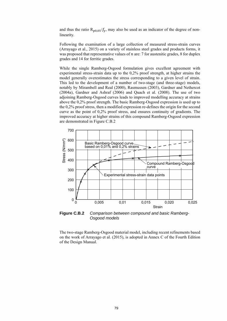
79
and thus the ratio R , / , may also be used as an indicator of the degree of non-linearity.
Following the examination of a large collection of measured stress-strain curves (Arrayago et al., 2015) on a variety of stainless steel grades and products forms, it was proposed that representative values of are: 7 for austenitic grades, 8 for duplex grades and 14 for ferritic grades.
While the single Ramberg-Osgood formulation gives excellent agreement with experimental stress-strain data up to the 0,2% proof strength, at higher strains the model generally overestimates the stress corresponding to a given level of strain. This led to the development of a number of two-stage (and three-stage) models, notably by Mirambell and Real (2000), Rasmussen (2003), Gardner and Nethercot (2004a), Gardner and Ashraf (2006) and Quach et al. (2008). The use of two adjoining Ramberg-Osgood curves leads to improved modelling accuracy at strains above the 0,2% proof strength. The basic Ramberg-Osgood expression is used up to the 0,2% proof stress, then a modified expression re-defines the origin for the second curve as the point of 0,2% proof stress, and ensures continuity of gradients. The improved accuracy at higher strains of this compound Ramberg-Osgood expression are demonstrated in Figure C.B.2
Figure C.B.2 Comparison between compound and basic Ramberg-Osgood models
The two-stage Ramberg-Osgood material model, including recent refinements based on the work of Arrayago et al. (2015), is adopted in Annex C of the Fourth Edition of the Design Manual.
600
700
500
400
300
200
100
0
Str
ess
(N/m
m²)
0
Compound Ramberg-Osgoodcurve
Experimental stress-strain data points
Strain0,005 0,01 0,015 0,020 0,025
Basic Ramberg-Osgood curve based on 0,01% and 0,2% strains
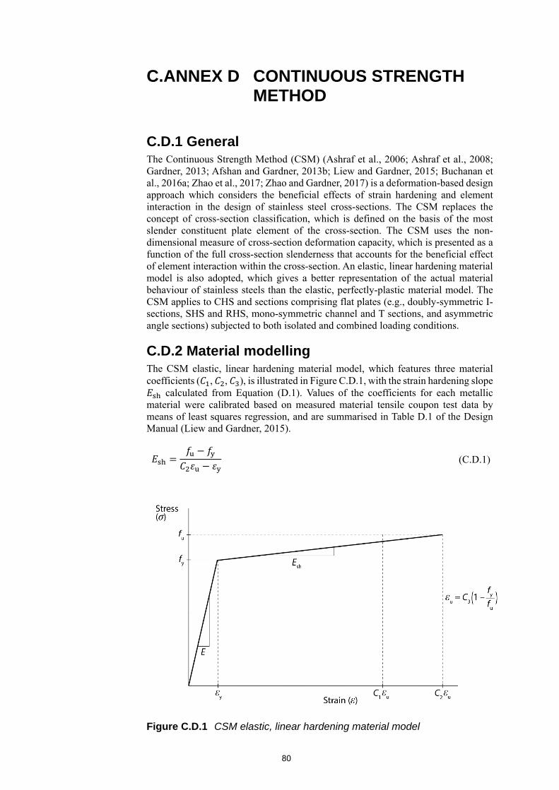
80
C.ANNEX D CONTINUOUS STRENGTH METHOD
C.D.1 General The Continuous Strength Method (CSM) (Ashraf et al., 2006; Ashraf et al., 2008; Gardner, 2013; Afshan and Gardner, 2013b; Liew and Gardner, 2015; Buchanan et al., 2016a; Zhao et al., 2017; Zhao and Gardner, 2017) is a deformation-based design approach which considers the beneficial effects of strain hardening and element interaction in the design of stainless steel cross-sections. The CSM replaces the concept of cross-section classification, which is defined on the basis of the most slender constituent plate element of the cross-section. The CSM uses the non-dimensional measure of cross-section deformation capacity, which is presented as a function of the full cross-section slenderness that accounts for the beneficial effect of element interaction within the cross-section. An elastic, linear hardening material model is also adopted, which gives a better representation of the actual material behaviour of stainless steels than the elastic, perfectly-plastic material model. The CSM applies to CHS and sections comprising flat plates (e.g., doubly-symmetric I-sections, SHS and RHS, mono-symmetric channel and T sections, and asymmetric angle sections) subjected to both isolated and combined loading conditions.
C.D.2 Material modelling The CSM elastic, linear hardening material model, which features three material coefficients ( , , ), is illustrated in Figure C.D.1, with the strain hardening slope
calculated from Equation (D.1). Values of the coefficients for each metallic material were calibrated based on measured material tensile coupon test data by means of least squares regression, and are summarised in Table D.1 of the Design Manual (Liew and Gardner, 2015).
(C.D.1)
Figure C.D.1 CSM elastic, linear hardening material model
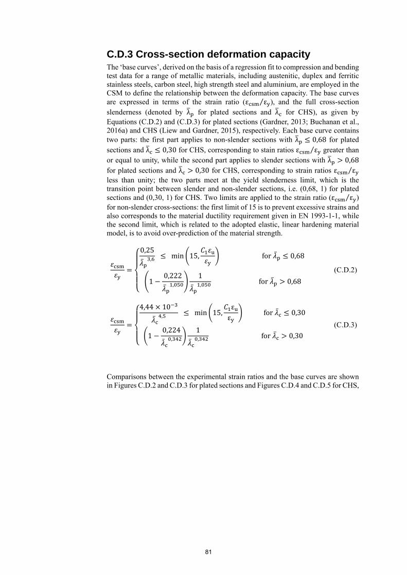
81
C.D.3 Cross-section deformation capacity The ‘base curves’, derived on the basis of a regression fit to compression and bending test data for a range of metallic materials, including austenitic, duplex and ferritic stainless steels, carbon steel, high strength steel and aluminium, are employed in the CSM to define the relationship between the deformation capacity. The base curves are expressed in terms of the strain ratio (ε ε⁄ ), and the full cross-section slenderness (denoted by λ for plated sections and λ for CHS), as given by Equations (C.D.2) and (C.D.3) for plated sections (Gardner, 2013; Buchanan et al., 2016a) and CHS (Liew and Gardner, 2015), respectively. Each base curve contains two parts: the first part applies to non-slender sections with λ 0,68 for plated sections and λ 0,30 for CHS, corresponding to stain ratios ε ε⁄ greater than or equal to unity, while the second part applies to slender sections with λ 0,68 for plated sections and λ 0,30 for CHS, corresponding to strain ratios ε ε⁄ less than unity; the two parts meet at the yield slenderness limit, which is the transition point between slender and non-slender sections, i.e. (0,68, 1) for plated sections and (0,30, 1) for CHS. Two limits are applied to the strain ratio (ε ε⁄ ) for non-slender cross-sections: the first limit of 15 is to prevent excessive strains and also corresponds to the material ductility requirement given in EN 1993-1-1, while the second limit, which is related to the adopted elastic, linear hardening material model, is to avoid over-prediction of the material strength.
0,25
, min 15, for 0,68
10,222
,
1
, for 0,68
(C.D.2)
4,44 10
, min 15,εε
for 0,30
10,224
,
1
, for 0,30 (C.D.3)
Comparisons between the experimental strain ratios and the base curves are shown in Figures C.D.2 and C.D.3 for plated sections and Figures C.D.4 and C.D.5 for CHS,

82
respectively.
Figure C.D.2 CSM base curve for non-slender plated sections with collected experimental data
Figure C.D.3 CSM base curve for slender plated sections with collected experimental data
0
5
10
15
20
25
0.0 0.1 0.2 0.3 0.4 0.5 0.6 0.7 0.8 0.9
ε csm
/εy
Cross-section slenderness
Stainless steel (C)
Stainless steel (B)
Carbon steel (C)
0.0
0.2
0.4
0.6
0.8
1.0
1.2
1.4
1.6
1.8
2.0
0.6 0.8 0.9 1.1 1.2 1.4 1.5 1.7 1.8
ε csm
/εy
Cross-section slenderness
Stainless steel (C)
Stainless steel (B)
Aluminum (C)
Aluminum (B)
High strength steel (C)
Carbon steel (C)
0,68 CSM base curve for plated sections with
(C) - compression (B) - bending
CSM base curve for plated sections with 0,68
(C) - compression (B) - bending

83
Figure C.D.4 CSM base curve for non-slender CHS with collected experimental data
Figure C.D.5 CSM base curve for slender CHS with collected experimental data
C.D.4 Cross-section compression resistance Upon determination of the maximum attainable strain ε and the corresponding strain hardening modulus , the CSM design stress for stainless steel cross-sections under pure compression can be calculated from Equation (C.D.4) for non-slender sections with design strains greater than or equal to the yield strain (ε ε⁄ 1) and Equation (C.D.5) for slender sections with design strains less than the yield strain (ε ε⁄ 1), respectively. Note that Equation (C.D.5) represents the strain hardening behaviour of the material through the strain hardening
0
5
10
15
20
25
0.0 0.1 0.2 0.3 0.4 0.5 0.6 0.7
ε csm
/εy
Cross-section slenderness
Hot-finished structural steel (C)Very high strength structural steel (C)Cold-formed structural steel (C)Stainless steel (C)Aluminium (C)Hot-finished structural steel (B)Very high strength structural steel (B)Cold-formed structural steel (B)Stainless steel (B)Aluminium (B)
(C) - compression(B) - bending
0.5
1.0
1.5
2.0
2.5
0.3 0.4 0.5 0.6 0.7
ε csm
/εy
Cross-section slenderness
Very high strength structural steel (C)
Cold-formed structural steel (C)
Stainless steel (C)
Aluminium (C)
Very high strength structural steel (B)
Cold-formed structural steel (B)
Stainless steel (B)
Aluminium (B)
(C) - compression(B) - bending
CSM base curve for CHS with 0,3
CSM base curve for CHS with 0,3
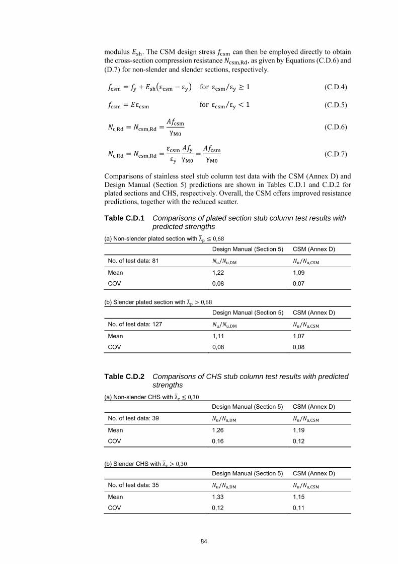
84
modulus . The CSM design stress can then be employed directly to obtain the cross-section compression resistance , , as given by Equations (C.D.6) and (D.7) for non-slender and slender sections, respectively.
ε ε for ε ε 1⁄ (C.D.4)
ε for ε ε 1⁄ (C.D.5)
, , γ (C.D.6)
, ,εε γ γ
(C.D.7)
Comparisons of stainless steel stub column test data with the CSM (Annex D) and Design Manual (Section 5) predictions are shown in Tables C.D.1 and C.D.2 for plated sections and CHS, respectively. Overall, the CSM offers improved resistance predictions, together with the reduced scatter.
Table C.D.1 Comparisons of plated section stub column test results with predicted strengths
(a) Non-slender plated section with λ 0,68
Design Manual (Section 5) CSM (Annex D)
No. of test data: 81 / , / ,
Mean 1,22 1,09
COV 0,08 0,07
(b) Slender plated section with λ 0,68
Design Manual (Section 5) CSM (Annex D)
No. of test data: 127 / , / ,
Mean 1,11 1,07
COV 0,08 0,08
Table C.D.2 Comparisons of CHS stub column test results with predicted strengths
(a) Non-slender CHS with λ 0,30
Design Manual (Section 5) CSM (Annex D)
No. of test data: 39 / , / ,
Mean 1,26 1,19
COV 0,16 0,12
(b) Slender CHS with λ 0,30
Design Manual (Section 5) CSM (Annex D)
No. of test data: 35 / , / ,
Mean 1,33 1,15
COV 0,12 0,11

85
C.D.5 Cross-section bending resistance C.D.5.1 Bending about an axis of symmetry For doubly symmetric sections (SHS, RHS, and CHS) and mono-symmetric sections (channel sections and T-sections) in bending about an axis of symmetry, the maximum attainable strain ε is determined from Equations (C.D.2) and (C.D.3). The design stress distribution can then be derived based on the elastic, linear hardening material model.
For slender sections with a design strain ratio less than unity (ε /ε 1), there is an elastic, linear-varying stress distribution and no benefit arises from strain hardening; the bending moment resistance , is thus directly calculated as the elastic bending moment resistance multiplied by the strain ratio, as given by Equation (C.D.8).
, ,εε γ
(C.D.8)
For non-slender sections with a design strain ratio greater than or equal to unity (ε /ε 1), , was firstly derived analytically through integration of the design stress distribution throughout the cross-section depth, and then transformed into a simplified design formula, as given by Equation (C.D.9), where α is the CSM bending coefficient, related to cross-section shape and axis of bending, as shown in Table C.D.3.
, , γ1
εε
1 1εε
(C.D.9)
Table C.D.3 Summary of the CSM bending parameter
Cross-section type Axis of bending Aspect ratio
SHS/RHS Any Any 2,0
CHS Any – 2,0
I-section y-y Any 2,0
z-z Any 1,2
Channel section
y-y Any 2,0
z-z ⁄ 2 1,5
⁄ 2 1,0
T-section y-y
⁄ 1 1,0
⁄ 1 1,5
z-z Any 1,2
Angle y-y Any 1,5
z-z Any 1,0
A quantitative evaluation of the CSM u,CSM and Design Manual (Section 5) u,DM bending resistance predictions against available experimental data u is reported in Tables C.D.4 and C.D.5 for plated sections and CHS in bending about an axis of symmetry. The CSM is found to yield a higher level of design accuracy and consistency in predicting the cross-section bending moment resistances than the Design Manual.
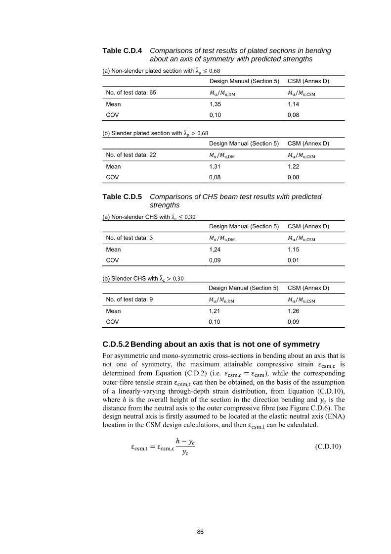
86
Table C.D.4 Comparisons of test results of plated sections in bending about an axis of symmetry with predicted strengths
(a) Non-slender plated section with λ 0,68
Design Manual (Section 5) CSM (Annex D)
No. of test data: 65 / , / ,
Mean 1,35 1,14
COV 0,10 0,08
(b) Slender plated section with λ 0,68
Design Manual (Section 5) CSM (Annex D)
No. of test data: 22 / , / ,
Mean 1,31 1,22
COV 0,08 0,08
Table C.D.5 Comparisons of CHS beam test results with predicted
strengths
(a) Non-slender CHS with λ 0,30
Design Manual (Section 5) CSM (Annex D)
No. of test data: 3 / , / ,
Mean 1,24 1,15
COV 0,09 0,01
(b) Slender CHS with λ 0,30
Design Manual (Section 5) CSM (Annex D)
No. of test data: 9 / , / ,
Mean 1,21 1,26
COV 0,10 0,09
C.D.5.2 Bending about an axis that is not one of symmetry
For asymmetric and mono-symmetric cross-sections in bending about an axis that is not one of symmetry, the maximum attainable compressive strain ε , is determined from Equation (C.D.2) (i.e. ε , ε ), while the corresponding outer-fibre tensile strain ε , can then be obtained, on the basis of the assumption of a linearly-varying through-depth strain distribution, from Equation (C.D.10), where h is the overall height of the section in the direction bending and is the distance from the neutral axis to the outer compressive fibre (see Figure C.D.6). The design neutral axis is firstly assumed to be located at the elastic neutral axis (ENA) location in the CSM design calculations, and then ε , can be calculated.
ε , ε , (C.D.10)
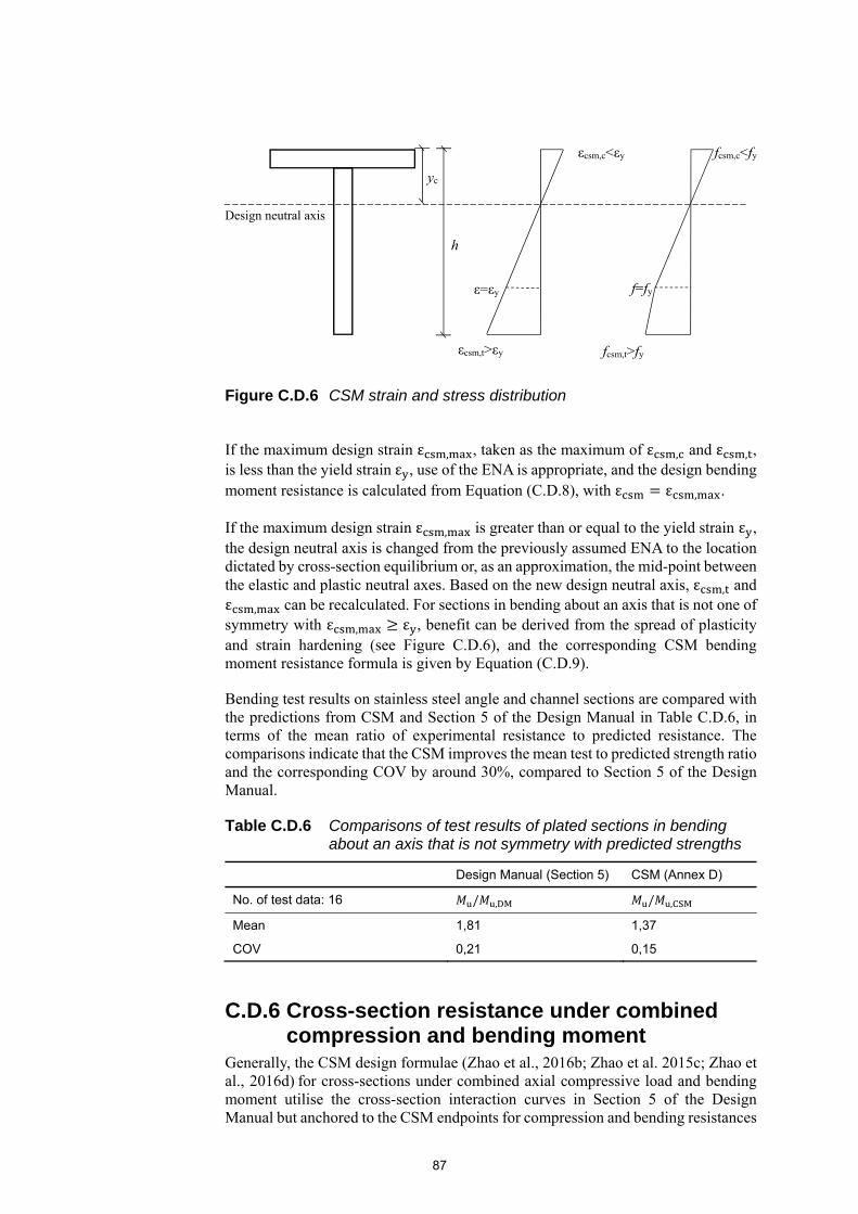
87
Figure C.D.6 CSM strain and stress distribution
If the maximum design strain ε , , taken as the maximum of ε , and ε , , is less than the yield strain ε , use of the ENA is appropriate, and the design bending moment resistance is calculated from Equation (C.D.8), with ε ε , .
If the maximum design strain ε , is greater than or equal to the yield strain ε , the design neutral axis is changed from the previously assumed ENA to the location dictated by cross-section equilibrium or, as an approximation, the mid-point between the elastic and plastic neutral axes. Based on the new design neutral axis, ε , and ε , can be recalculated. For sections in bending about an axis that is not one of symmetry with ε , ε , benefit can be derived from the spread of plasticity and strain hardening (see Figure C.D.6), and the corresponding CSM bending moment resistance formula is given by Equation (C.D.9).
Bending test results on stainless steel angle and channel sections are compared with the predictions from CSM and Section 5 of the Design Manual in Table C.D.6, in terms of the mean ratio of experimental resistance to predicted resistance. The comparisons indicate that the CSM improves the mean test to predicted strength ratio and the corresponding COV by around 30%, compared to Section 5 of the Design Manual.
Table C.D.6 Comparisons of test results of plated sections in bending about an axis that is not symmetry with predicted strengths
Design Manual (Section 5) CSM (Annex D)
No. of test data: 16 / , / ,
Mean 1,81 1,37
COV 0,21 0,15
C.D.6 Cross-section resistance under combined compression and bending moment
Generally, the CSM design formulae (Zhao et al., 2016b; Zhao et al. 2015c; Zhao et al., 2016d) for cross-sections under combined axial compressive load and bending moment utilise the cross-section interaction curves in Section 5 of the Design Manual but anchored to the CSM endpoints for compression and bending resistances
Design neutral axis
fcsm,c<fy
f=fy
εcsm,c<εy
yc
ε=εy
h
εcsm,t>εy fcsm,t>fy
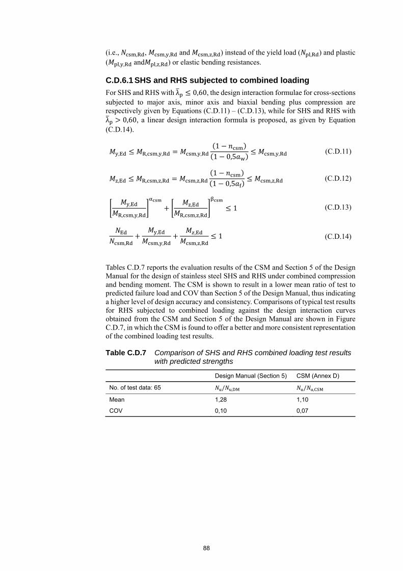
88
(i.e., , , , , and , , ) instead of the yield load ( , ) and plastic ( , , and , , ) or elastic bending resistances.
C.D.6.1 SHS and RHS subjected to combined loading
For SHS and RHS with λ 0,60, the design interaction formulae for cross-sections subjected to major axis, minor axis and biaxial bending plus compression are respectively given by Equations (C.D.11) – (C.D.13), while for SHS and RHS with λ 0,60, a linear design interaction formula is proposed, as given by Equation (C.D.14).
, , , , , ,11 0,5 , , (C.D.11)
, , , , , ,11 0,5 , , (C.D.12)
,
, , ,
,
, , ,1 (C.D.13)
,
,
, ,
,
, ,1 (C.D.14)
Tables C.D.7 reports the evaluation results of the CSM and Section 5 of the Design Manual for the design of stainless steel SHS and RHS under combined compression and bending moment. The CSM is shown to result in a lower mean ratio of test to predicted failure load and COV than Section 5 of the Design Manual, thus indicating a higher level of design accuracy and consistency. Comparisons of typical test results for RHS subjected to combined loading against the design interaction curves obtained from the CSM and Section 5 of the Design Manual are shown in Figure C.D.7, in which the CSM is found to offer a better and more consistent representation of the combined loading test results.
Table C.D.7 Comparison of SHS and RHS combined loading test results with predicted strengths
Design Manual (Section 5) CSM (Annex D)
No. of test data: 65 / , / ,
Mean 1,28 1,10
COV 0,10 0,07
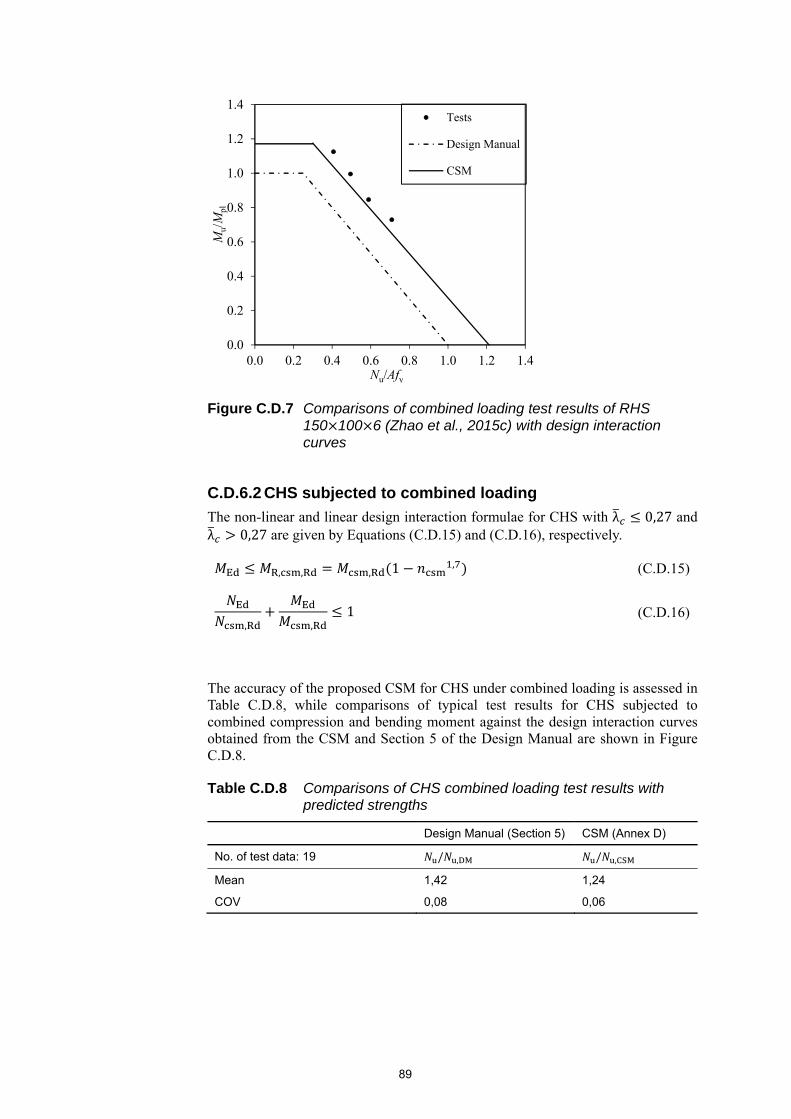
89
Figure C.D.7 Comparisons of combined loading test results of RHS 150 100 6 (Zhao et al., 2015c) with design interaction curves
C.D.6.2 CHS subjected to combined loading
The non-linear and linear design interaction formulae for CHS with λ 0,27 and λ 0,27 are given by Equations (C.D.15) and (C.D.16), respectively.
, , , 1 , (C.D.15)
, ,1 (C.D.16)
The accuracy of the proposed CSM for CHS under combined loading is assessed in Table C.D.8, while comparisons of typical test results for CHS subjected to combined compression and bending moment against the design interaction curves obtained from the CSM and Section 5 of the Design Manual are shown in Figure C.D.8.
Table C.D.8 Comparisons of CHS combined loading test results with predicted strengths
Design Manual (Section 5) CSM (Annex D)
No. of test data: 19 / , / ,
Mean 1,42 1,24
COV 0,08 0,06
0.0
0.2
0.4
0.6
0.8
1.0
1.2
1.4
0.0 0.2 0.4 0.6 0.8 1.0 1.2 1.4
Mu/
Mpl
Nu/Afy
Tests
Design Manual
CSM

90
Figure C.D.8 Comparisons of combined loading test results of CHS 114.3 3 (Zhao et al., 2016d) with design interaction curves
0
0.2
0.4
0.6
0.8
1
1.2
1.4
0 0.2 0.4 0.6 0.8 1 1.2 1.4
Mu/
Mpl
Nu/Aσ0,2
Tests
Design Manual
CSM

91
C.ANNEX E ELASTIC CRITICAL MOMENT FOR LATERAL TORSIONAL BUCKLING
The various formulae presented in Annex E of the Design Manual are taken from the SCI publication Stability of steel beams and columns (Gardner, 2011).
92
REFERENCES
Afshan, S. and Gardner, L. (2013a). Experimental study of cold-formed ferritic stainless steel hollow sections. Journal of Structural Engineering, ASCE. 139(5), 717-728.
Afshan, S. and Gardner, L. (2013b). The continuous strength method for structural stainless steel design. Thin-Walled Structures. 68(4), 42-49
Afshan, S., Rossi, B. and Gardner, L. (2013). Strength enhancements in cold-formed structural sections – Part I: Material testing. Journal of Constructional Steel Research. 83, 177-188.
Afshan, S., Francis, P., Baddoo, N.R. and Gardner, L. (2015). Reliability analysis of structural stainless steel design provisions. Journal of Constructional Steel Research. 114, 293-304.
Afshan, S., Gardner, L., Zhao, O. and Ho. E. (2016). Buckling of stainless steel columns in fire. Proceedings of the Sixth International Conference on Structural Engineering, Mechanics and Computation. Cape Town, South Africa.
Afshan, S., Zhao, O. and Gardner, L. (2017). Standardised material properties for numerical parametric studies of structural stainless steel elements. Stainless Steel in Structures – Fifth International Experts Seminar. London, UK.
Afzali, N., Pilhagen, J., Manninen, T., Schedin, E. and Stranghöner, N. (2017), Preload losses in stainless steel bolting assemblies. Steel Construction, 10: 310–318.
AISI (2007). Specification for the design of cold-formed steel structural members. American Iron and Steel Institute.
Ala-Outinen, T. (1996). Fire resistance of austenitic stainless steels Polarit 725 (EN 1.4301) and Polarit 761 (EN 1.4571). Research Notes 1760. Technical Research Centre of Finland (VTT), Finland.
Ala-Outinen, T. and Oksanen, T. (1997). Stainless steel compression members exposed to fire. Research Notes 1864. Technical Research Centre of Finland (VTT), Finland.
Albertini, C. and Montagnani, M. (1976). Wave propagation effects in dynamic loading. Nuclear Engineering and Design. 37, 115-124.
Arrayago, I., Real, E. and Gardner, L. (2015). Description of stress-strain curves for stainless steel alloys. Materials and Design. 87, 540-552.
Ashraf, M., Gardner, L. and Nethercot, D.A. (2005). Strength enhancements induced during cold forming of stainless steel sections. Journal of Constructional Steel Research. 61(1), 37-52.
Ashraf, M., Gardner, L. and Nethercot, D.A. (2006). Compression strength of stainless steel cross-sections. Journal of Constructional Steel Research. 62(1), 105-115.
93
Ashraf, M., Gardner, L. and Nethercot, D.A. (2008). Structural stainless steel design: Resistance based on deformation capacity. Journal of Structural Engineering, ASCE. 134(3), 402-411.
ASME (2004). Boiler and pressure vessel code. American Society of Mechanical Engineers, New York.
ASTM (2017) ASTM A380/A380M-17 Standard Practice for Cleaning, Descaling, and Passivation of Stainless Steel Parts, Equipment, and Systems, ASTM.
Baddoo, N.R., Burgan, R. and Ogden, R.O. (1995). Architects’ guide to stainless steel. P179. The Steel Construction Institute, UK.
Baddoo, N.R. (2008) Stainless Steel in Construction: A Review of Research, Applications, Challenges and Opportunities. Journal of Constructional Steel Research, 64, 1199-1206.
Baddoo, N.R. (2013). 100 years of stainless steel: A review of structural applications and the development of design rules. The Structural Engineer. Volume 91, Issue 8.
Baddoo, N.R. (2014). Execution of stainless steel structures. The Steel Construction Institute ED018.
Bardi, F. and Kyriakides, S. (2006). Plastic buckling of circular tubes under axial compression – Part I: Experiments. International Journal of Mechanical Sciences. 48(8), 830-841.
Bock, M., Arrayago, I., Real, E and Mirambell, E. (2013). Study of web crippling in ferritic stainless steel cold formed sections. Thin-Walled Structures. 69, 29-44.
Bock, M. and Real, E. (2014). Strength curves for web crippling design of cold-formed stainless steel hat sections. Thin-Walled Structures. 85, 93-105.
Bock, M., Mirada, F.X., and Real, E. (2015). Statistical evaluation of a new resistance model for cold-formed stainless steel cross-sections subjected to web crippling. International Journal of Steel Structures. 15(1), 227-244.
BS 5950-1 (2000). Structural use of steelwork in building. Code of practice for design – rolled and welded sections. British Standards Institution, UK.
BS 5950-5 (1998). Structural use of steelwork in building. Code of practice for design of cold formed thin gauge sections. British Standards Institution, UK.
Bu, Y. and Gardner, L. (2017). Finite element modelling and design of welded stainless steel I-section columns. Stainless Steel in Structures – Fifth International Experts Seminar. London, UK.
Buchanan, C., Gardner, L. and Liew, A. (2016a). The continuous strength method for the design of circular hollow sections. Journal of Constructional Steel Research. 118, 207-216.
Buchanan, C., Real, E. and Gardner, L. (2016b). Beam-column behaviour of ferritic stainless steel CHS members. Proceedings of the Seventh International Conference on Coupled Instabilities in Metal Structures. Baltimore, Maryland.
94
Buchanan, C., Real, E. and Gardner, L. (2016c). Testing and design of stainless steel CHS columns. Proceedings of the Eighth International Conference on Steel and Aluminium Structures. Hong Kong.
Burgan, B.A., Baddoo, N.R. and Gilsenan, K.A. (2000). Structural design of stainless steel members-comparison between Eurocode 3, Part 1.4 and test results. Journal of Constructional Steel Research. 54, 51-73.
Cadoni, E., Fenu, L. and Forni, D (2012). Strain rate behaviour in tension of austenitic stainless steel used for reinforcing bars. Construction and Building Materials 35 399-407. Cai, Y. and Young, B. (2014a). Structural behaviour of cold-formed stainless steel bolted connections. Thin-Walled Structures. 83, 147-156.
Cai, Y. and Young, B. (2014b). Transient state tests of cold-formed stainless steel single shear bolted connections. Engineering Structures. 81, 1-9.
Cai, Y. and Young, B. (2015). High temperature tests of cold-formed stainless steel double shear bolted connections. Journal of Constructional Steel Research. 104, 49-63.
Cai, Y. and Young, B. (2016). Bearing factors of cold-formed stainless steel double shear bolted connections at elevated temperatures. Thin-Walled Structures. 98, 212-229.
Chen, J. and Young, B. (2006). Stress-strain curves for stainless steel at elevated temperatures. Engineering Structures. 28(2), 229-239.
Coetzee, J.S., van der Berg, G.J. and van der Merwe, P. (1990). The behaviour of stainless steel lipped channel axially loaded compression members. Report MD-55. Faculty of Engineering, Rand Afrikaans University.
Cruise, R.B., and Gardner, L. (2008). Strength enhancements induced during cold forming of stainless steel sections. Journal of Constructional Steel Research. 64(11), 1310-1316.
Dier, A.F. (1987). Comparison of steel and aluminium plate strengths. Proceedings of International Conference on Steel and Aluminium Structures. Cardiff, UK.
Dobrić, J., Buđevac, D., Marković, Z., and Gluhović, N. (2017). Behaviour of stainless steel press-braked channel sections under compression. Journal of Constructional Steel Research. 139, 236-253.
Dobrić, J., Pavlović, M., Marković, Z., Buđevac, D. and Spremić, M. (2018). Resistance of cold-formed built-up stainless steel members – Part II: Numerical simulation. Journal of Constructional Steel Research. 140, 247-260.
Dodd, B., Stone, R.C. and Campbell, J.D. (1973). The strain-rate sensitivity of 304L austenitic stainless steel in uniaxial tension. Engineering Laboratory Report No. 1069/73. University of Oxford, Oxford.
Dowling, P.J. and Burgan, B.A. (1987). Shear lag in steel and composite structures: A state of the art review. Proceedings of International Conference on Steel and Aluminium Structures. Cardiff, UK.
95
EN 1011-3 (2000). Welding. Recommendations for welding of metallic materials. Arc welding of stainless steels. CEN
EN 1090-2:2008+A1:2011 (2011). Execution of steel structures and aluminium structures. Technical requirements for the execution of steels structures. CEN.
EN 1990:2002+A1 (2005). Eurocode – Basis of structural design. CEN.
EN 1993-1-1 (2005). Eurocode 3: Design of steel structures: Part 1.1 General rules and rules for buildings. CEN.
EN 1993-1-2 (2005). Eurocode 3: Design of steel structures – Part -1-2: General rules – Structural fire design. CEN.
EN 1993-1-3 (2006). Eurocode 3: Design of steel structures – Part 1-3: General rules – Supplementary rules for cold formed members and sheeting. CEN.
EN 1993-1-4 (2006+A1:2015). Eurocode 3: Design of steel structures: General rules. Supplementary rules for stainless steel. British Standards Institution, London.
EN 1993-1-5 (2006). Eurocode 3: Design of steel structures – Part 1-5: Plated structural elements. CEN.
EN 1993-1-8 (2005). Eurocode 3: Design of steel structures – Part 1-8: Design of joints. CEN.
EN 1993-1-9 (2005). Eurocode 3: Design of steel structures – Part 1-9: Fatigue. CEN.
EN 10002-1 (2001). Tensile testing of metallic materials. Method of test at ambient temperature. CEN.
EN 10088-1 (2005). Stainless steels: List of stainless steels. CEN.
EN 10088-4 (2009). Stainless steels: Technical delivery conditions for sheet/plate and strip of corrosion resisting steels for general purposes. CEN.
EN 10088-5 (2009). Stainless steels: Technical delivery conditions for semi-finished products, bars, rods and sections for general purposes. CEN.
EN 10204 (2004). Metallic products: Types of inspection documents. CEN.
EN 15643-1 (2010) Sustainability of construction works. Sustainability assessment of buildings. General framework
EN 15643-2 (2011) Sustainability of construction works. Assessment of buildings. Framework for the assessment of environmental performance
EN 15804 (2012+A1:2013) Sustainability of construction works. Environmental product declarations. Core rules for the product category of construction products
EN 15942 (2011) Sustainability of construction works. Environmental product declarations. Communication format business-to-business
CEN/TR 15941 (2010) Sustainability of construction works. Environmental product declarations. Methodology for selection and use of generic data

96
EN 15978 (2011) Sustainability of construction works. Assessment of environmental performance of buildings. Calculation method
ENV 1993-1-2 (1995). Eurocode 3: Design of steel structures. Structural fire design. CEN.
ENV 1993-1-3 (1996). Eurocode 3: Design of steel structures. General rules. Supplementary rules for cold formed thin gauge members and sheeting. CEN.
ENV 1993-1-4 (1996). Eurocode 3: Design of steel structures. General rules. Supplementary rules for stainless steels. CEN.
ENV 1993-1-5 (1997). Eurocode 3: Design of steel structures. General rules. Supplementary rules for plated planar structures without transverse loading. CEN.
EN ISO 3506 (2009). Mechanical properties of corrosion-resistant stainless steel fasteners CEN.
EN ISO 9606-1 (2017). Qualification test of welders. Fusion welding. Steels. CEN.
EN ISO 15609-1 (2004). Specification and qualification of welding procedures for metallic materials. Welding procedure specification. Arc Welding. CEN.
Errera, S.J., Tang, B.M. and Popowich, D.W. (1970). Strength of Bolted and Welded Connections in Stainless Steel. Report No.355. Department of Structural Engineering, Cornell University.
Errera, S.J., Popowich, D.W. and Winter, G. (1974). Bolted and welded stainless steel connections. Journal of the Structural Division, ASCE. 100, 1279-1296.
Estrada, I., Real, E. and Mirambell, E. (2007). General behaviour and effect of rigid and nonrigid end post in stainless steel plate girders loaded in shear. Part II: Extended numerical study and design proposal. Journal of Constructional Steel Research. 63(7), 985-996.
Euro Inox (ed.) (2005a). Guide to stainless steel finishes. Building series – Volume 1. 2nd Edition. Euro Inox (available from www.worldstainless.org).
Euro Inox (ed.) (2005b) The mechanical finishing of decorative stainless steel surfaces. Materials and Application Series, Volume 6 (available from www.worldstainless.org)
Euro Inox (ed.) (2006a). The forming potential of stainless steel. Materials and Applications Series – Volume 8. Euro Inox (available from www.worldstainless.org).
Euro Inox (ed.) (2006b). Erection and installation of stainless steel components. Building Series – Volume 10. Euro Inox, (available from www.imoa.info)
Euro Inox (ed.) (2007). Pickling and passivating stainless steel. Materials and Applications Series – Volume 4. Euro Inox, Second Edition (available from www.worldstainless.org).
Euro Inox (ed.) (2013). Safe use of stainless steel in swimming pool environments (available from www.imoa.info)

97
European Commission (2002). Development of the use of stainless steel in construction. Final Report. Directorate-General for Research and Innovation EUR 20030.
European Commission (2006). Structural design of cold worked austenitic stainless steel. Final Report. Directorate-General for Research and Innovation EUR 21975.
European Commission (2008). Application of duplex stainless steel for welded bridge construction in an aggressive environment. Final Report. Directorate-General for Research and Innovation EUR 23595
European Commission (2009). Stainless steel in fire. Final Report. Directorate-General for Research and Innovation EUR 23745.
European Commission (2015). Structural applications of ferritic stainless steels. Final Report. Directorate-General for Research and Innovation EUR 27089.
European Commission (2018). Execution and reliability of slip-resistant connections for steel structures using CS and SS (SIROCO), RFSR-CT-2014-00024, to be published in 2018.
Fan, S., Ding, X., Sun, W., Zhang, L. and Liu, M. (2016a). Experimental investigation on fire resistance of stainless steel columns with square hollow section. Thin-Walled Structures. 98, 196-211.
Fan, S., Zhang, L., Sun, W., Ding, X., and Liu, M. (2016b). Numerical investigation on fire resistance of stainless steel columns with square hollows section under axial compression. Thin-Walled Structures. 98, 185-195.
Fan, S., He, B., Xia, X., Gui, H., and Liu, M. (2016c). Fire resistance of stainless steel beams with rectangular hollow section: Experimental investigation. Fire Safety Journal. 81, 17-31.
Fan, S., Chen, G., Xia, X., Ding, Z., and Liu, M. (2016d). Fire resistance of stainless steel beams with rectangular hollow section: Numerical investigation and design. Fire Safety Journal. 79, 69-90.
Gardner, L. (2002). A new approach to structural stainless steel design. Ph.D Thesis, Imperial College London.
Gardner, L. and Nethercot, D.A. (2004a). Experiments on stainless steel hollow sections – Part 1: Material and cross-sectional behaviour. Journal of Constructional Steel Research. 60(9), 1291-1318.
Gardner, L. and Nethercot, D.A. (2004b). Experiments on stainless steel hollow sections – Part 2: Member behaviour of columns and beams. Journal of Constructional Steel Research. 60(9), 1319-1332.
Gardner, L. and Ng, K. T. (2006). Temperature development in structural stainless steel sections exposed to fire. Fire Safety Journal. 41(3), 185-203.
Gardner, L. and Ashraf, M. (2006). Structural design for non-linear metallic materials. Engineering Structures. 28(6), 926-934.
Gardner, L. and Baddoo, N.R. (2006). Fire testing and design of stainless steel structures. Journal of Constructional Steel Research. 62(6), 532-543.
98
Gardner, L., Talja, A. and Baddoo, N. (2006). Structural design of high-strength austenitic stainless steel. Thin-Walled Structures. 44(5), 517-528.
Gardner, L. and Theofanous, M. (2008). Discrete and continuous treatment of local buckling in stainless steel elements. Journal of Constructional Steel Research. 64(11), 1207-1216.
Gardner, L., Insausti, A., Ng, K.T. and Ashraf, M. (2010). Elevated temperature material properties of stainless steel alloys. Journal of Constructional Steel Research. 66(5), 634-647.
Gardner, L. (2011) Stability of steel beams and columns, P360 The Steel Construction Institute
Gardner, L. (2011). Stability of beams and columns. SCI Publication No. P360. The Steel Construction Institute, UK.
Gardner, L. (2013). The continuous strength method. Proceedings of the Institution of Civil Engineers – Structures and Buildings. 161(3), 127-133.
Gardner, L., Bu, Y., Francis, P., Baddoo, N.R., Cashell, K.A. and McCann, F. (2016a). Elevated temperature material properties of stainless steel reinforcing bar. Construction and Building Materials. 114, 977-997.
Gardner, L., Bu, Y. and Theofanous, M. (2016b). Laser-welded stainless steel I-sections: residual stress measurements and column buckling tests. Engineering Structures. 127, 536-548.
Granlund, J. (1997). Structural steel plasticity – Experimental study and theoretical modelling. Ph.D. thesis, Luleå University of Technology.
Greiner, R. (2005). Proposal for buckling rules in EN 1993-1-4. ECCS/TC8-2005-005 Committee Document. University of Graz, Austria.
Gurney, T.R. (1978). Fatigue of welded structures. 2nd Edition. Cambridge University Press.
Gurney, T.R. and Maddox, S.J. (1973). A re-analysis of fatigue data for welded joints in steel. Welding Research International. 3(4), 1-54.
Harding, J.E., Hobbs, R.E., Neal, B.G. and Slatford, J.E. (1976). Parametric study on plates under combined direct and shear in-plane loading. Engineering Structures Laboratories Report No. BG 44. Civil Engineering Department, Imperial College London.
Hill, H.N. (1944). Determination of stress-strain relations from the offset yield strength values. Technical Note No. 927, National Advisory Committee for Aeronautics. Washington, D.C.
Houska, C. (2014) Stainless Steels in architecture, building and construction: guidelines for corrosion prevention. No. 11 024 Nickel Institute (available from www.nickelinstitute.org ).
Hradil, P., Chen, A. and Baddoo, N. (2017), Numerical modelling of stainless steel preloaded bolted connections. Steel Construction, 10: 344–353.
99
Huang, Y. and Young, B. (2012). Material properties of cold-formed lean duplex stainless steel sections. Thin-Walled Structures. 54, 72-81.
Huang, Y. and Young, B. (2014a). Stress-strain relationship of cold-formed lean duplex stainless steel at elevated temperatures. Journal of Constructional Steel Research. 92, 103-113.
Huang, Y. and Young, B. (2014b). Experimental investigation of cold-formed lean duplex stainless steel beam-columns. Thin-Walled Structures. 76, 105-117.
Inco Europe Limited (1963). Austenitic chromium-nickel stainless steels – Engineering properties at elevated temperatures. Inco Databooks, distributed by the Nickel Development Institute. (available from www.nickelinstitute.org)
Inco Europe Limited (1974). Materials for cryogenic service – Engineering properties of austenitic stainless steels. Inco Databooks, distributed by the Nickel Development Institute. (available from www.nickelinstitute.org)
IMOA (2014) Practical guidelines for the fabrication of duplex stainless steel. Third Edition, International Molybdenum Association (available from www.imoa.info)
James, E.A. and Jubb J.E.M. (1972). The fatigue strength of fillet welded joints in 18-8 type austenitic steels, ambient and low temperatures. Australian Welding Journal. 10(7), 19-21.
James, L.A. (1976). Fatigue crack propagation in austenitic stainless steel. Atomic Energy Review. 14(1), 37-86.
Japanese Institution of Architecture (1988). Strength and deformation of H-shaped stainless steel beams. Journal of the Kanto Branch, Japanese Institution of Architecture. (In Japanese)
Johnson, A.L. and Winter, G. (1966a). Behaviour of stainless steel columns and beams. Journal of the Structural Division, ASCE. 92, 97-118.
Johnson, A.L. and Winter, G. (1966b). The structural performance of austenitic stainless steel members. Report No. 327. Department of Structural Engineering, School of Civil Engineering, Cornell University.
Jones, J.L.; Koul, M.G.; Schubbe, J.J. (2014) An Evaluation of the Corrosion and Mechanical Performance of Interstitially Surface-Hardened Stainless Steel. Journal of Materials Engineering and Performance 23 (6) pp. 2055–2066
Karren, K.W. (1967). Corner properties of cold-formed steel shapes. Journal of the Structural Division, ASCE. 93(1), 401-432.
Kiymaz, G. (2005). Strength and stability criteria for thin-walled stainless steel circular hollow section members under bending. Thin-Walled Structures. 43, 1534-1549.
Koskimäki, M. and Niemi, E. (1995). Fatigue strength of welded joints in three types of stainless steel. IIW Document No. XIII-1603-95. International Institute of Welding.
Krempl, E. (1979). An experimental study of room-temperature rate-sensitivity, creep and relaxation of AISI type 304 stainless steel. Journal of the Mechanics and Physics of Solids. 27, 363-375.
100
Kuwamura, H. (2001). Local buckling consideration in design of thin-walled stainless steel members. Lecture at Pusan National University.
Kuwamura, H. (2003). Local buckling of thin-walled stainless steel members. Steel Structures. 3(3), 191-201.
Lam, D. and Gardner, L. (2008). Structural design of stainless steel concrete filled columns. Journal of Constructional Steel Research. 64, 1275-82.
Liew, A. and Gardner, L. (2015). Ultimate capacity of structural steel cross-sections under compression, bending and combined loading. Structures. 1, 2-11.
Lichtenfeld, J. A., Van Tyne, C. and Mataya, M. (2006). Effect of strain rate on stress-strain behavior of alloy 309 and 304L austenitic stainless steel. Metallurgical and Materials Transactions A 37.1: 147-161
Lihavainen, V., Niemi, E. and Viherma, R. (2000). WP7: Fatigue. ECSC Project - Development of the use of stainless steel in construction, Contract No. 7210 SA/904. Outokumpu.
Liu, Y. and Young B. (2003). Buckling of stainless steel square hollow section compression members. Journal of Constructional Steel Research. 59(2), 165-177.
Lui, W.M., Ashraf, M. and Young, B. (2014). Test of cold-formed duplex stainless steel SHS beam-columns. Engineering Structures. 74, 111-121.
Maddox, S.J. (1974). Fatigue crack propagation data obtained from parent plate weld metal and HAZ in structural steels. Welding Research International. 4(1), 26-60.
Maddox, S.J. (1997). Developments in fatigue design codes and fitness-for-service assessment methods. Proceedings of the International Conference on Performance of Dynamically Loaded Welded Structures (IIW 50th Annual Assembly Conference). San Francisco, USA.
Marquis, G.B. (1995). High cycle spectrum fatigue of welded components. Ph.D. Thesis, published as VTT publication 240. Technical Research Centre of Finland (VTT), Espoo.
Marshall, P. (1984). Microstructure and mechanical properties. Austenitic Stainless Steels. Springer, Netherlands.
Mathers, E. and Jubb, J.E.M. (1973). The fatigue of stainless steel fillet welds at low temperatures. Welding Institute Conference on Welding Low Temperature Containment Plant, London. 130-139. (and IIW Doc/ XIII-743-1974)
McClintock, A., Scholz, W. and Hayward, P. (1990). Comparison of stainless steel welding processes (HERA Report R8-03). New Zealand Heavy Engineering Research Association, Auckland, New Zealand.
Mirambell, E. and Real, E. (2000). On the calculation of deflections in structural stainless steel beam: An experimental numerical investigation. Journal of Constructional Steel Research. 54(1), 109-133.
New Steel Construction (2016) New rules on the selection of execution class for structural steel, Advisory Desk 394, New Steel Construction
101
Olsson, A. (2001). Stainless steel plasticity – Material modelling and structural applications. Ph.D. Thesis, Luleå University of Technology.
Outokumpu (2008). Anisothermal tests on stainless steel grades. Confidential Outokumpu report.
Outokumpu (2009). The Outokumpu Corrosion handbook. 10th Edition. (Available from www.outokumpu.com)
Outokumpu (2010). The Outokumpu Welding Handbook. (Available from www.outokumpu.com)
Outokumpu (2013a). The Outokumpu Handbook of stainless steel. (Available from www.outokumpu.com)l
Outokumpu (2013b). Environmental Product Declarations according to ISO 14025 and EN 15804. (Available from www.outokumpu.com).
Owens, G.W. and Cheal, B.D. (1989). Structural Steelwork Connections. Butterworth and Company Limited.
Paquette, J.A. and Kyriakides, S. (2006). Plastic buckling of tubes under axial compression and internal pressure. International Journal of Mechanical Sciences. 48, 855-867.
Quach, W.M., Teng, J.G. and Chung, J.F. (2008). Three-stage full-range stress-strain model for stainless steels. Journal of Structural Engineering. 134(9), 1518-1527.
Ramberg, W. and Osgood, W.R. (1943). Description of stress-strain curves by three parameters. Technical Note No. 902, National Advisory Committee for Aeronautics. Washington, D.C.
Rasmussen, K.J.R (2000). Recent research on stainless steel tubular structures. Journal of Constructional Steel Research. 54, 75-88.
Rasmussen, K.J.R. (2003). Full-range stress-strain curves for stainless steel alloys. Journal of Constructional Steel Research. 59(1), 47-61.
Rasmussen, K.J.R. and Hancock, D.A. (1993). Design of cold-formed stainless steel tubular members I: Columns. Journal of Structural Engineering, ASCE. 119(8), 2349-2367.
Rasmussen, K.J.R. and Hancock, G.J. (1990). Stainless steel tubular columns – Tests and design. Proceedings of the Tenth International Speciality Conference on Cold-Formed Steel Structures. St. Louis, Missouri, USA.
Razmjoo, G. (1995). Design guidance on fatigue of welded stainless steel joints. Proceedings of Offshore Mechanical and Arctic Engineering Conference (OMAE ’95). Materials Engineering, ASME. 3, 163-171.
Real, E. (2001). Aportaciones al studio del comportamiento a flexion de estructuras de acero inoxiddable. Tesis Doctoral. Departamento de Ingeniería de la Construcción, Universitat Politècnica de Catalunya. UPC-ETSECCP. Barcelona, Spain. (In Spanish).
Real, E. and Mirambell, E. (2005). Flexural behaviour of stainless steel beams. Engineering Structures. 27 (6) 1465-1475

102
Real, E., Mirambell, E. and Estrada, I. (2007). Shear response of stainless steel plate girders. Engineering Structures. 29(7), 1626-1640.
Rhodes, J., Macdonald, M. and McNiff, W. (2000). Buckling of cold-formed stainless steel columns under concentric and eccentric loading. Fifteenth International Specialty Conference on Cold-Formed Steel Structures. St. Louis, Missouri, USA.
Roark’s formulas for stress and strain, (2012). 8th Edition. McGraw-Hill International Book Company.
Rossi, B. (2014). Discussion on the use of stainless steel in constructions in view of sustainability Thin-Walled Structures. 83, 181-189.
Rossi, B., Afshan, S. and Gardner, L. (2013). Strength enhancements in cold-formed structural sections – Part II: Predictive models. Journal of Constructional Steel Research. 83, 189-196.
Ryan, I. (1999). WP4.2. Bolted connections ECSC Project - Development of the use of stainless steel in construction, Contract No. 7210 SA/327
Sakumoto, Y., Nakazato, T. and Matsuzaki, A. (1996). High-temperature properties of stainless steel for building structures. Journal of Structural Engineering, ASCE. 122(4), 399-406.
Saliba, N. and Gardner L. (2013a). Experimental study of the shear response of lean duplex stainless steel plate girders. Engineering Structures. 46, 375-391.
Saliba, N. and Gardner, L. (2013b). Cross-section stability of lean duplex stainless steel welded I-sections. Journal of Constructional Steel Research. 80, 1-14.
Saliba, N. Real, E. and Gardner L. (2014). Shear design recommendations for stainless steel plate girders. Engineering Structures. 59, 220-228.
Salih, E.L., Gardner, L. and Nethercot, D.A. (2010). Numerical investigation of net section failure in stainless steel bolted connections. Journal of Constructional Steel Research. 66(12), 1455-1466.
Salih, E.L., Gardner, L. and Nethercot, D.A. (2011). Bearing failure in stainless steel bolted connections. Engineering Structures. 33(2), 549-556.
Salih, E.L., Gardner, L. and Nethercot, D.A. (2013). Numerical study of stainless steel gusset plate connections. Engineering Structures. 49, 448-464.
Sanderson, G.P. and Llewellyn, D.T. (1969). Mechanical properties of standard austenitic stainless steels in the temperature range -196° to +800°. Journal of the Iron and Steel Institute. 207, 1129-1140.
SCI (1990). Technical Report 21: Interim Results for Test Programme on Connections. SCI-RT157. The Steel Construction Institute, UK.
SCI (1991). Test on stainless steel materials. Technical Report SCI-RT-251. The Steel Construction Institute, UK.
SCI (1999). Design guide for stainless steel blast walls. Fire and Blast Information Group Technical Note 5. The Steel Construction Institute, UK.
103
Sedlacek, G. and Ungermann, D. (2002). Evaluation of test results on columns and beam-columns with cross-sectional class IV in order to obtain strength functions and suitable model factors. Background report to Eurocode 3 “Common unified rules for steel structures”. Chapter 5, Document 5.04. Prepared for the Commission of the European Communities. CEN TC/250/SC3 committee document. The Steel Construction Institute, UK.
SEI/ASCE 8-02 (2002). Specification for the design of cold-formed stainless steel structural members. American Society of Civil Engineers, New York.
Selen, E. (2000). WP3.5: Web crippling. ECSC Project – Development of the use of stainless steel in construction, Contract No. 7210 SA/903. Luleå University of Technology.
Speck, J.A. (2015) Fastener Functions and Assembly Testing, Second Edition, CRC Press, Taylor & Francis Group
Stout, M.G. and Follansbee, P.S. (1986). Strain rate sensitivity, strain hardening, and yield behaviour of 304L stainless steel. Journal of Engineering Materials and Technology. 108, 344-353.
Stranghöner, N., Jungbluth, D., Abraham, C. and Söderman, A. (2017a), Tightening behaviour of preloaded stainless steel bolting assemblies. Steel Construction, 10: 319–332.
Stranghöner, N., Afzali, N., de Vries, P., Schedin, E., Pilhagen, J. and Cardwell, S. (2017b), Slip-resistant bolted connections of stainless steel. Steel Construction, 10: 333–343.
Talja, A. (1997). Test report on welded I and CHS beams, columns and beam-columns. Report to the ECSC. Technical Research Centre of Finland (VTT), Finland.
Talja, A. (2000). Design of stainless steel members and sheetings. Internal project summary report No. RTE38-IR-6/2000. Technical Research Centre of Finland (VTT), Finland.
Talja, A. and Salmi, P. (1995). Design of stainless steel RHS beams, columns and beam-columns. Research Note 1619. VTT Building Technology, Finland.
Talja, A., Vilpas, M., Huhtala, L. and Yrjölä, P. (2003). Design of welded connections of cold worked stainless steel RHS members. Stainless Steel in Structures – Second International Experts Seminar. Ascot, The Steel Construction Institute.
Taylor, D. (1984). A compendium of fatigue thresholds and growth rates. EMAS.
Theofanous, M. and Gardner, L. (2009). Testing and numerical modelling of lean duplex stainless steel hollow section columns. Engineering Structures. 31(12), 3047-3058.
Theofanous, M., Chan, T.M. and Gardner, L. (2009). Structural response of stainless steel oval hollow section compression members. Engineering Structures. 31(40), 922-934.
Theofanous, M., Saliba, N., Zhao, O. and Gardner, L. (2014). Ultimate response of stainless steel continuous beams. Thin-Walled Structures. 83, 115-127.

104
Timoshenko, S. (1956). Strength of materials. Part II advanced theory and problems. 3rd Edition. Van Nostrand Reinhold Company, New York. 366-374.
To, E. and Young, B. (2008). Performance of cold-formed stainless steel tubular columns at elevated temperatures. Engineering Structures. 30(7), 2012-2021.
Tondini, N., Rossi, B. and Franssen, J.M. (2013). Experimental investigation on ferritic stainless steel columns in fire. Fire Safety Journal. 62, 238-248.
Tuthill, A.H. (1986). Fabrication and post-fabrication cleanup of stainless steels. Chemical Engineering. 93(18). (Also available from the Nickel Development Institute, NiDI Technical Series No. 10004 from www.nickelinstitute.org)
Uy, B., Tao, Z. and Han, L.H. (2011). Behaviour of short and slender concrete-filled stainless steel tubular columns. Journal of Constructional Steel Research. 67, 360-378.
van den Berg, G.J. (1988). The torsional flexural buckling strength of cold-formed stainless steel columns. Ph.D. Thesis, Rand Afrikaans University.
van den Berg, G.J., and van der Merwe, P. (1992). Prediction of corner mechanical properties for stainless steels due to cold forming. Eleventh International Speciality Conference on Cold-Formed Steel Structures. Missouri, USA. 571-586.
van den Berg, G.J. and van der Merwe, P. (1988). The torsional flexural buckling strength of cold-formed stainless steel columns. Report MD-47. Faculty of Engineering, Rand Afrikaans University.
van der Merwe, P. (1987). Development of design criteria for ferritic stainless steel cold-formed structural members and connections. Ph.D. Thesis, University of Missouri-Rolla.
Van Wyk, M.L., van der Berg, G.J. and van der Merwe, P. (1990). The lateral torsional buckling strength of doubly symmetric stainless steel beams. Report MD-58. Faculty of Engineering, Rand Afrikaans University.
Walport, F., Gardner, L., Real, E., Arrayago, I. and Nethercot, D.A. (2017). Effects of material nonlinearity on the global analysis and stability of stainless steel frames. Journal of Construction Steel Research. (Under review)
Wasén, J., Karlsson, B. and Nyström, M. (1990). Fatigue crack growth properties of SAF 1.4462. Nordic Symposium on Mechanical Properties of Stainless Steels. Sigtuna, Sweden.
White, P.E. and Hemingway, R.D. (1969). Mechanical joints in stainless steel. Stainless Steels, Iron and Steel Institute publication. 117, 85-93.
Winter, G. (1968). Thin-walled structures – Theoretical solutions and test results. Proceedings of the International Association for Bridge and Structural Engineering Eighth Congress. NY, USA. 101-112.
Young, B. and Hartono, W. (2002). Compression tests of stainless steel tubular members. Journal of Structural Engineering, ASCE. 128(6), 754-761.
Young, B. and Liu, Y. (2003). Experimental investigation of cold-formed stainless steel columns. Journal of Structural Engineering, ASCE. 129(2), 169-176.
105
Young, B. and Lui, W.M. (2005). Behaviour of cold-formed high strength stainless steel sections. Journal of Structural Engineering, ASCE. 131(11), 1738-1745.
Young, B. and Lui, W.M. (2006). Tests on cold formed high strength stainless steel compression members. Thin-Walled Structures. 44(2), 224-234.
Zahural Islam, S.M., and Young, B. (2014). FRP strengthening of lean duplex stainless steel hollow sections subjected to web crippling. Thin-Walled Structures. 85, 183-200.
Zhao, O., Gardner, L. and Young, B. (2015a). Structural performance of stainless steel circular hollow sections under combined axial load and bending – Part 1: Experiments and numerical modelling. Thin-Walled Structures. 101, 231-239.
Zhao, O., Rossi, B., Gardner, L. and Young, B. (2015b). Behaviour of structural stainless steel cross-sections under combined loading – Part I: Experimental study. Engineering Structures. 89, 236-246.
Zhao, O., Rossi, B., Gardner, L. and Young, B. (2015c). Behaviour of structural stainless steel cross-sections under combined loading – Part II: Numerical modelling and design approach. Engineering Structures. 89, 247-259.
Zhao, O., Gardner, L. and Young, B. (2016a). Buckling of ferritic stainless steel members under combined axial compression and bending. Journal of Constructional Steel Research. 117, 35-48.
Zhao, O., Rossi, B., Gardner, L. and Young, B. (2016b). Experimental and numerical studies of ferritic stainless steel tubular cross sections under combined compression and bending. Journal of Structural Engineering, ASCE. 142(2), 04015110.
Zhao, O., Gardner, L. and Young, B. (2016c). Testing and numerical modelling of austenitic stainless steel CHS beam-columns. Engineering Structures. 111, 263-274.
Zhao, O., Gardner, L. and Young, B. (2016d). Structural performance of stainless steel circular hollow sections under combined axial load and bending – Part 2: Parametric studies and design. Thin-Walled Structures. 101, 240-248.
Zhao, O., Gardner, L. and Young, B. (2016e). Behaviour and design of stainless steel SHS and RHS beam-columns. Thin-Walled Structures. 106, 330-345.
Zhao, O. and Gardner, L. (2017). Design of non-doubly symmetric stainless steel sections in bending. Journal of Constructional Steel Research. (Under review)
Zhao, O., Afshan, S. and Gardner, L. (2017). Structural response and continuous strength method design of slender stainless steel cross-sections. Engineering Structures. 140, 14-25.
Zhou, F. and Young, B. (2005). Tests of cold-formed stainless steel tubular flexural members. Thin-Walled Structures. 43, 1325-1337.
Zhou, F. and Young, B. (2008). Web crippling of cold-formed stainless steel tubular sections. Advances in Structural Engineering. 11(6), 679-691.
Zhou, F. and Young, B. (2013). Web crippling behaviour of cold-formed duplex stainless steel tubular sections at elevated temperatures. Engineering Structures. 57, 51-62.

Stainless steel is used for a wide range of structural applications in aggressive environments where reliable performance over long periods with little maintenance is required. In addition, stainless steel has an attractive appearance, is strong yet still light, highly ductile and versatile in terms of manufacturing.
This Design Manual gives design rules for austenitic, duplex and ferritic stainless steels. The rules are aligned to the 2015 amendment of the Eurocode for structural stainless steel, EN 1993-1-4. They cover the design of cross-sections, members, connections and design at elevated temperatures as well as new design methods which exploit the beneficial strain hardening characteristics of stainless steel. Guidance on grade selection, durability and fabrication is also provided. Fifteen design examples are included which illustrate the application of the design rules.
The purpose of this Commentary to the Recommendations is to allow the designer to assess the basis of the recommendations and to facilitate the development of revisions as and when new data become available. Opportunity is taken to present the results of various test programmes which provide background data for the Recommendations in the Design Manual and a full set of references.
DESIGN MANUAL FOR STRUCTURAL STAINLESS STEEL4TH EDITION - COMMENTARY
SCISilwood Park, Ascot, Berkshire. SL5 7QN UKT: +44 (0)1344 636525F: +44 (0)1344 636570E: [email protected] www.steel-sci.com
SCI Ref: P421