Instructional Design Document Machining Mechanics STAM Interactive Solutions.
Design, Machiningand Installation
Manual
C O N T E N T SPAGE
INTRODUCTION 1
APPLICATIONS 2
LUBRICATION 3-5
GRADE SELECTION 6-7
BEARING CONFIGURATION 8-10
Standard available forms
SHAFT MATERIAL CHOICE 11-12
Surface finish and tolerances
DIMENSIONING 13-21
Length to diameter ratioWall thicknessGroove configuration and dimensionsOD/ID calculationA Graphical formatB Calculations from first principlesC Computer ProgrammeInformation required from the user
RETENTION METHODS 22-23
MACHINING 24-34
Health, handling and storage conditions
FITTING METHODS 35-36
APPROVALS 37
Appendices (Machining Graphs) 38-47
INTRODUCTION
TENMAT FEROFORM MARINE BEARINGS are used in many diverse application areasacross all vessel types. The UNIVERSAL nature of the material means that one basicgrade (T14) can be used with all manner of fluids from clean water through to heavilyabrasive laden conditions, for greases/oils through to various fuels and chemicals. For dryself lubricating bearing applications or where dry start up or indeed where lubricationstarvation may be encountered, or where noise free running is a pre-requisite, then graphite(T11) or molybdenum disulphide (T12) containing grades are available to cater for thesespecial needs.
These advanced HIGHLY TECHNOLOGICAL composites are setting new standards ofwear resistance, versatility and reliability for marine bearings and are thus able to offer theShip Owner, Operator, Shipyard and Naval Architect a number of substantial cost savings.
This manual gives details of the Design Criteria, Machining Data and Fitting Instructions forFEROFORM Marine Bearings and bushes in all application areas including propeller shafts,rudders, stabilisers, pumps, general deck equipment such as winches, windlasses, davits,fair leads, cargo handling equipment and hatch covers and also for off-shore/dockside applications.
Our experienced Technical Services Department are available to discuss and advise onall aspects of Marine Bearing use. Please Telephone [+44] (0)161 872 2181.Alternatively, Fax [+44] (0)161 872 7596 for assistance.
IMPORTANT NOTICE
Tenmat welcomes the use of this manual or the associated C.D. ROM. However, any copiesof the document must be transposed in its entirety, including this notice. No partial copyamendments are authorised without the express written permission of Tenmat Ltd.
The information offered in this document is only relevant to Tenmat Ltd. products ormaterials and is only offered to assist engineers in the overall deisgn of marine stern tubeand rudder bearings. The information herein is presented in good faith but Tenmat does notwarrant the conformity of its materials to the listed properties or the suitability of itsmaterials for any particular purpose. Therefore, the final design of the bearing / systemmust be the responsibility of the appropriate approval society, shipyard, ship-owner orarchitect.
1

APPLICATIONS
FEROFORM Marine Bearings exhibit a versatility of applicational use unsurpassed by anyother materials. This is made possible by the very wide range of physical, chemical andmechanical properties inherent in FEROFORM.
FEROFORM’s major attributes are:
Resistance to abrasive conditionsHigh mechanical strengthWide operational temperature rangeLow frictionNo stick slipResistance to shock loadsVery low water swellNo oil swellHigh PV limit dryCan be lubricated by any compatible fluid (oil, water, grease etc)Excellent chemical resistance
As a consequence of this unique versatility FEROFORM Marine Bearings have beensuccessfully used in a very wide range of applications including:
Hull structure:Propeller shaft - stern tubes and bracketsRudders - all typesStabilisersBow thrustersCP Propeller e.g. pitch adjustment slides
Deck equipment:Hatch covers - bearings and slide padsWinches and WindlassesFairleadsDavitsStern rollersRo-Ro ramps and doors
Other ship borne equipment:PumpsCargo handling e.g. expansion pads, containerhanding & Cable laying equipment
Other Naval applications:Submarines - hydroplane
mast bearings e.g. periscope, communications mast
2
LUBRICATION
Any compatible fluid can be used to lubricate FEROFORM bearings. Generally water, oilor grease is used the choice being dependent on whether the system is open or closed, andthe speed of operation.
Under certain circumstances FEROFORM T11 or T12 grades can be used withoutlubrication e.g. where speed is so low as to not generate any significant heat.
It is strongly recommended that wherever an unlubricated application is considered ourTechnical Department is consulted in order that combined pressure and velocity effects (PVlimits) can be evaluated.
WATER
Water is commonly used with FEROFORM T14 grade propeller shaft, impeller, pump,stabiliser and lower rudder bearings.
For high speed, full rotation applications (e.g. propeller shaft) it is generally preferred tohave a positive water flow. Rotational speed generates heat and being such a good coolingmedium, water is an ideal lubricant in these conditions.
The flow rate should be high enough to fully dissipate any heat produced by the rotationalspeed.
A minimum flow rate of 0.15 litres per minute per mm of shaft diameter is recommended.
This flow rate is good for all speeds and does not have to be increased for high rotationalspeeds. This is because at high speed, hydrodynamic lubrication films are formedsignificantly decreasing friction and therefore reducing heat generation.
Water lubrication systems are normally of the open type i.e. no aft seal.
Water should be supplied at the innermost point of the bearing line.
Since FEROFORM has high temperature resistance and does not suffer from hydrolysis,engine cooling water may be used to lubricate the stern tube bearings.
L:D ratios and groove configurations are described fully in section entitled “Dimensions”.
OIL
Commonly used as lubricant in stern tubes. Oil is normally considered to be a betterlubricant than water but not such a good coolant.
Also, oil must be used in a closed system (fully sealed). Systems traditionally used withwhite metal bearings are perfectly satisfactory for use with FEROFORM bearings.
3

Such systems include:
a) Gravity flow from header tank through stern tube to drain tank. The oil is then normally pumped back to the header tank perhaps via a cooler.
b) Thermally induced flow where the stern tube is often kept cool by flooding the after peak.
c) Full circulation by pump.
Generally any SAE30 marine quality stern tube oil is acceptable, However, in a closed, oillubricated system it is not normal practice to use corrosion resistant (stainless) materials.Therefore it is recommended that an emulsifiable oil is used so that in the event of wateringress, no free water will exist in the system thereby preventing potential corrosion.
Vickers Hydrox 550 oil is an acceptable example of such an emulsifiable oil.
Flow rates in the order of 0.01 litres per minute per mm of shaft diameter have beenrecorded.
NOTE:
THERE ARE TWO VERY SIGNIFICANT SAFETY FACTORS ASSOCIATED WITH USINGFEROFORM IN THE EVENT OF (CATASTROPHIC) SEAL FAILURE:-
1. FEROFORM IS FULLY APPROVED TO OPERATE WITH WATER LUBRICATION ANDEVEN IF THE SYSTEM UTILISES NON-CORROSION RESISTANT MATERIALS WATERCAN BE SAFELY USED TO REACH PORT.
2. POLLUTION PROBLEMS ARE RESTRICTED SINCE THE OIL SUPPLY CAN BE SHUTOFF AND WATER INJECTED INTO THE SYSTEM INSTEAD.
GREASE
Grease will not readily flow and hence does not offer any cooling effect.
Grease is therefore normally used where heat generation is not significant - namely veryslow rotation or oscillatory motion as in a rudder application.
Also where bearings are used fairly infrequently, such as hatch covers, grease is a goodchoice of lubricant since it protects metallic parts from corrosion.
4

Warning Ref Grease
Please note that we can assume due to load and speed, heat would be generated ina stern tube application. This should be taken as a WARNING against the use ofgrease in this application. However, we do have society approvals happy with theconcept and designs. This is a warning only for stern tube, therefore excluding therudder application.
SEALS
Experience has shown that all approved seals can be used in conjunction with TENMAT’sFEROFORM bearings.
No special requirements are necessary; fitting and operation should be in accordance withthe seal manufacturer’s recommendations.
PV LIMITS
PV need only be considered when heat is likely to be produced and not dissipated by thelubrication medium.
i.e. For an open, water lubricated system, assuming a flow rate of 0.15 litres per minute permm of shaft diameter is used, there would be no need to consider PV since the water flowwill more than adequately dissipate any heat produced.
As water has a very good cooling effect on the bearing, PV values well in excess of 1000kg/cm2 m/min are achievable for propeller shaft bearings. In fact 2000 PV would be wellwithin the capability of FEROFORM `T’ grades under hydrodynamic conditions.
For an oil lubricated system if the PV exceeds 275 MPa m/min then use of oil coolers in thesystem may be necessary. Please consult our Technical Department for advice.
See also table “Guide to Limiting PV Value” in section entitled GRADE SELECTION.
FRICTION
Extensive friction data is available in dry, wet or oil lubricated conditions. Should frictionlevels with any of these particular media be required please consult TENMAT Limited.
Values down to 0.01 have been recorded where hydrodynamic lubrication conditions exist.
5

GRADE SELECTION
All FEROFORM Marine grades are non-asbestos synthetic fibres impregnated withphenolic resins.
FEROFORM T14
The universal grade for fluid lubricated conditions. Therefore in most marine applicationsT14 is acceptable since lubrication will be present as oil, grease, water or the chemicalbeing handled. For the rudder application the latest 10 MPa high pressure approval byleading societies gives further bonuses.
FEROFORM T11
The matrix additionally incorporates evenly dispersed graphitic filler. T11 can be used withwater lubrication particularly where slow operational speeds are frequently used resultingin boundary lubrication conditions prevailing.
This grade can also operate dry (unlubricated) providing low frictional and high loadcarrying attributes up to a PV limit of 120 kg/cm2 m/min.
FEROFORM T12
Grade T12 incorporates molybdenum disulphide evenly dispersed throughout the matrix togive low friction at high pressure even when used dry.
For applications requiring low stick- slip, low noise and/or dry start-up T12 is often specifiede.g. by military users. Used where electrolytic corrosion could be a problem e.g. withgraphited materials.
For dry running a PV limit of 140 kg/cm2 m/min should be adhered to.
NOTE
All `T’ grades are fully approved by the leading Classification Societies for
Propeller Shaft Applications - water lubricated - open system.oil lubricated - closed system
Rudders - all types - water, grease or oil lubricated
FEROFORM F36
F36 is a grade specially developed for bearing and wearing applications at elevatedtemperatures - up to 200°C. It utilises a high temperature phenolic resin encapsulatingaramid composite textile reinforcement. 6

FEROFORM F363
As F36 but additionally incorporating graphite to provide low friction at high pressure andelevated temperature.
F36 and F363 also exhibit higher working pressure capability - 85 MPa (12320 lbf/in2) and75 MPa (10900 lbf/in2) respectively.
Used in marine equipment requiring combination of high pressure, high temperature andlow friction.
GUIDE TO LIMITING PV VALUE (Table 1)
Material Type
T14 390 (18,213) 780 (72,852) 300 (14,000)
360 (16,800)
380 (17,730)
16,000
2,000
240 (11,200)
260 (12,130)
1,200
1,500
410 (18500)
420 (19,590)
800
1,000
T11
T12
F36
F363
Dry RubbingOil Impregnated
(SAE 30 Oil)
Regular GreaseRe-lubrication
(Grade 2 Lithium)
PV values quoted are in kg/cm2 m/min (lbf/in2 ft/min) and derived from work done on mildsteel shafts - EN3B with 0.8 µmRa surface finish.
7

BEARING CONFIGURATION
All traditionally used configurations can be utilised either in a fully machined, ready-to-fitform, or semi-finished for final machining by the shipyard.
Where dimensions of the shaft and housing are pre-known e.g. new ship build, bearings canbe supplied fully finished but where shafts or housings may be re-worked to re-sleeve orclean off corrosion, for example, then semi-finished bearings should be ordered and finaldimensioning/machining carried out by the shipyard once shaft and housing diameters areconfirmed.
Full (Cylindrical) Bearings
This is generally the recommended configuration to use since machining, fitting andretention are all made easier by dealing with only one piece.
For example:Machining is basically just two operations - OD and ID.Retention can be by a simple interference fit.Fitting can be carried out by freeze fitting.
This is the most commonly used configuration for rudder and propeller shaft bearings.
Whilst FEROFORM `T’ grade tubes are manufactured in 1200mm lengths, for ease ofhandling and machining it may be preferred to use 600mm length pieces.
Split Bearings
Sometimes used where a need exists to be able to change a bearing without removing theshaft.
In such cases either mechanical methods of retention are used or if an interference fit isused a method has to be used whereby the interference can be broken mechanically. Thiscan be accomplished by use of for example tapered keys.
If a bush is split by milling, shims are normally used to fill the gap left by the cut. It ishowever possible to produce a split bush with no gap by splitting a semi-finished tube(having say 3-5mm oversize and undersize on OD and ID respectively), lightly bonding thetwo halves back together using say an anaerobic adhesive and mechanical strapping,machining OD and ID in the normal way and then breaking the bond.
Such split bushes can, if required, be retained by normal interference fit.
8
Flanged Bearings (Split or Full Cylindrical)
May be used where either the flange is utilised as a method of location/mechanicalretention or where a light axial load has to be accommodated.
NB High axial loads should be accommodated by a separate thrust ring and this wouldgenerally be a less expensive method to employ unless the flange were needed forlocation/retention/ removal consideration.
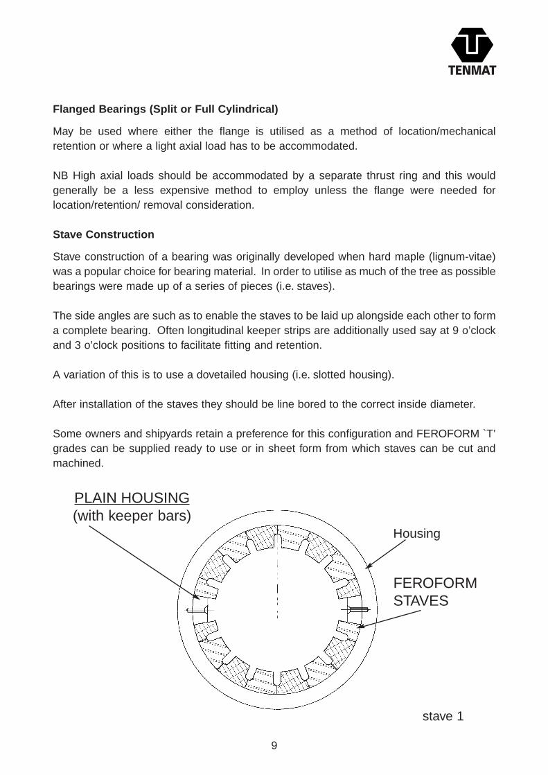
Stave Construction
Stave construction of a bearing was originally developed when hard maple (lignum-vitae)was a popular choice for bearing material. In order to utilise as much of the tree as possiblebearings were made up of a series of pieces (i.e. staves).
The side angles are such as to enable the staves to be laid up alongside each other to forma complete bearing. Often longitudinal keeper strips are additionally used say at 9 o’clockand 3 o’clock positions to facilitate fitting and retention.
A variation of this is to use a dovetailed housing (i.e. slotted housing).
After installation of the staves they should be line bored to the correct inside diameter.
Some owners and shipyards retain a preference for this configuration and FEROFORM `T’grades can be supplied ready to use or in sheet form from which staves can be cut andmachined.
9
PLAIN HOUSING(with keeper bars)
Housing
FEROFORMSTAVES
stave 1

STANDARD AVAILABLE FORMS
Tubes
Except for new build and OEM use where bearings can be supplied machined-to-drawingbearings are normally supplied semi-finished for final machining by the shipyard or repairer.
FEROFORM tubes are available to suit shaft diameters of 20mm to 1200mm (or larger onrequest). Tubes are of 1200mm standard maximum length but can be supplied as 900mmlengths to be more cost effective particulaly in urgent ship repair.
A standard size list is available.
Sheet
Standard sheet size is 1220mm x 1220mm in a range of thicknesses from 1.6mm to 75mm.(Thicker by request).
Staves
Available as required.
Some distributors keep a stock of some sizes.
10
DOVETAILED HOUSING
Each Segmentis normally suppliedwith flat internalface for machiningin the housing
Radii / Chamferafter turningbore

SHAFT MATERIAL CHOICE
All traditionally used bearing shaft materials can be used with FEROFORM bearings.
It is generally accepted that the harder the shaft (or liner/ sleeve) material, the better itswear resistance will be against almost any bearing material. This is particularly true forabrasive conditions in water lubricated systems.
Bronze
Strictly speaking bronze is an alloy of copper with tin but the word has become synonymouswith a superior material compared to brass.
Hence materials such as silicon bronze and aluminium bronze contain no tin.
The “bronzes” commonly used in marine applications are
1. Phosphor bronze.
2. Admiralty gunmetal.
3. Nickel aluminium bronze
4. Copper Nickel
Generally bronze shaft liners give good performance against FEROFORM bearings butalthough offering resistance to sea water and corrosion, easy machining and being non-magnetic bronzes should not be used where operating continuously in abrasive conditions;here a harder shaft liner should be used.
Steels
When carbon is alloyed with iron, the hardness and strength of the metal first increases e.g.steel containing 0.4% carbon may be twice the strength of pure iron and with 1% carbonnearly three times as strong.
However as carbon content increases ductility reduces.
From 1 to 1.5% carbon, hardness increases but strength begins to decrease. When itcontains more than 2´% carbon, the metal is classed as cast iron - having good castability,moderate strength and hardness but usually low ductility.
Steel Type Approximate % Carbon
Mild Steel Up to 0.25Medium Carbon Steel 0.25-0.45High Carbon Steel 0.45-1.5Cast Iron 2.5-4.5
11

Mild steel and medium carbon steel can be used in closed, oil lubricated systems i.e. wherecorrosion is unlikely.
For water lubricated systems corrosion resistant steels should be used.
In very abrasive operating conditions hard, corrosion resistant steel sleeves should beused.
Hard sleeves generally use a carbide coating (e.g. tungsten or boron carbide) and exhibit ahardness around 50-60 Rockwell C.
Stainless steels whilst offering corrosion resistance are not highly wear resistant. Likealuminium, stainless steels containing chromium achieve their corrosion resistance by theformation of a protective oxide film. It is this oxide film that primarily results in lower wearresistance, particularly in abrasive conditions. General commercial grades offerhardnesses of around 10-15 Rockwell C (180-200 Brinell) which are acceptable.
Stainless steels are however available with relatively high hardness and are preferred ifconditions are at all abrasive. Hardness should be greater than 30 Rockwell C.
The 18/8 stainless steels (austenitic) contain approximately 18% chromium and 8% nickel.They cannot be hardened by heat treatment but harden rapidly when cold worked.Molybdenum is often added to further increase corrosion resistance.
Another very good resistant alloy for sleeves is Inconel 625. This high nickel alloy (60%)work hardens, thus it is relatively easy to machine but hardens during operation.
SURFACE FINISH AND TOLERANCE
For Shafts
Experience has shown that a fine machine finish is an acceptable surface for FEROFORMbearings to operate against.
It is not necessary to polish the shaft liner or sleeve since this naturally occurs during theearly operational period. A surface finish of 0.8 micro metre (32 micro inch RMS) can bespecified.
Machining tolerances for shafts should be ISO tolerance h7(or h8).
For Housings
Out of round housings should be avoided. Again a H7 (or H8) ISO tolerance is preferred.
12

DIMENSIONING
LENGTH TO DIAMETER RATIO (L:D)
For industrial uses L:D ratios vary typically from 1:1 to 1.5:1.
An L:D of 1:1 can be considered optimum since it permits:
-adequate cross sectional area to provide acceptable bearing pressure.-ease of alignment (alignment becomes progressively more difficult the longer thebearing).-adequate outside surface area to permit retention by an interference fit.-good pressure distribution throughout bearing length.-allows a hydrodynamic film of lubrication to be readily established and retained.
Historically however for marine applications larger L:D ratios are used:
In oil lubricated propeller shaft systems typical permitted ratios are from 1.5:1 to 2:1.In water lubricated propeller shaft systems typical permitted ratios are from 2:1 to 4:1.For rudder bearings typical permitted ratios are from 1.8:1 to 2:1.
The historical reason for this is to keep the bearing pressure low.
Our experience indicates that the shortest possible L:D ratio should be used however Rulesand Regulations of the Classification Societies must be adhered to.
Since TENMAT FEROFORM T grades are capable of operating at very high pressures(more than 60 MPa) we are currently evaluating in conjunction with leading ClassificationSocieties use of reduced L:D ratios - particularly in propeller shaft applications.
WALL THICKNESS (W/T)
With a material such as FEROFORM exhibiting fairly high stiffness values wall thickness isnot normally a critical design criterion.
Therefore FEROFORM bearings can be used to replace bearings of virtually anydesign/size envelope.
Nonetheless given freedom of design the optimum wall thickness recommended is0.0625 d +2.5mm (where d is shaft diameter in mm).
This gives :-sufficient thickness for incorporation of grooves if required.-adequate wall thickness to permit interference fits to be used for retention.-cost effective use of material volume (i.e. optimum costs).-optimum stiffness (for ease of machine and fitting).
Should a thinner wall be required, the minimum recommended wall thickness is 0.05 d butTENMAT should be consulted if grooves are necessary in such a bearing.
13

GROOVE CONFIGURATION AND DIMENSIONS
A) Water Lubrication
Longitudinal lubrication grooves are recommended in accordance with Table 2
TABLE 2
ShaftDiameter
(mm)
20-7980-159160-239240-319320-399400-479480-559560-639640-719720-799800-879880-959960-1000
45678910111213141516
72605145403633302725242221
6101515202025252525252525
0.33 W/T
Numberof
Grooves
ApproxAngle
BetweenGrooves*
GroovesWidth(mm)
GroovesDepth(mm)
üïïïïýïïïïþ
They are primarily important to permit abrasive particles to pass easily and quickly throughthe bearing. They do not assist in the promotion and retention of a hydrodynamic film oflubrication and therefore to enhance this aspect it is recommended that the bottom (6o’clock) groove (in the loaded area) is omitted viz:
[* For propeller shaft bearings only]
T14 ID Groove Design for Water Lubricated Propeller Shaft Bearing
Optimum Wall thickness W/T = 0.0625 d + 2.5mm
Maximum groove depth g = 0.33 W/T. w = 2.5 g*. r = 0.33 g. N = number of grooves
NB. No groove at 6 o’clock position for propeller shaft bearings.
* Groove width is nominally 2.5 g, however to minimise the number of grooving toolsrequired, use the averaged groove widths specified in Table 2 for each particular shaft diam-eter.
14

B) Oil Lubrication
Since closed (sealed) oil lubricated systems offer a clean operating environmentlongitudinal grooves are not necessary and therefore it is recommended that “lead-in”(washway) grooves only are used, positioned at 9 o’clock and 3 o’clock, (or 10 o’clock and2 o’clock possibly in the case of twin screw vessels)
C) Grease Lubrication
Grease lubricated systems are generally used in very slow moving or oscillatory motionapplications such as rudders.
Here grooves are not necessary, although in some installations -dependent on the methodof supplying grease to the bearing - annular or closed end grooving may be used.
For grease lubricated propeller shafts, grooves should always be used as indicated in“water lubrication” section.
15
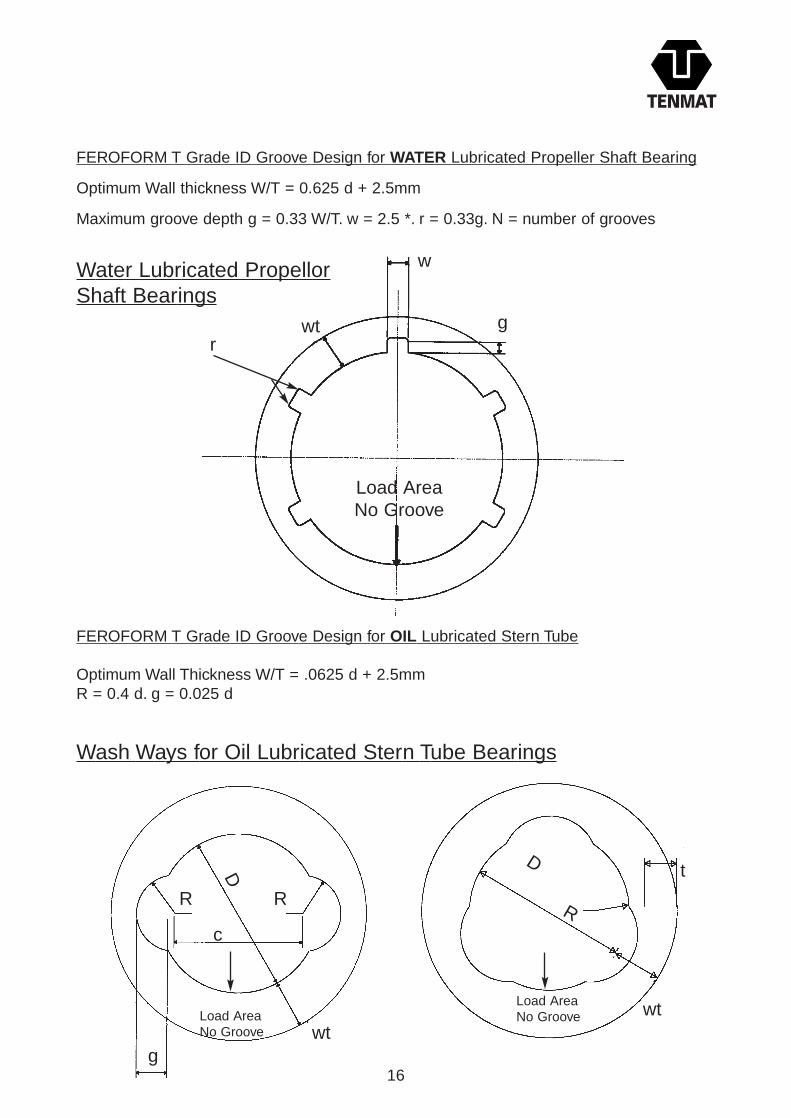
FEROFORM T Grade ID Groove Design for WATER Lubricated Propeller Shaft Bearing
Optimum Wall thickness W/T = 0.625 d + 2.5mm
Maximum groove depth g = 0.33 W/T. w = 2.5 *. r = 0.33g. N = number of grooves
FEROFORM T Grade ID Groove Design for OIL Lubricated Stern Tube
Optimum Wall Thickness W/T = .0625 d + 2.5mmR = 0.4 d. g = 0.025 d
16
Water Lubricated PropellorShaft Bearings
w
rwt g
Load AreaNo Groove
Wash Ways for Oil Lubricated Stern Tube Bearings
R R
wtg
c
Load AreaNo Groove
D
wt
D
R
t
Load AreaNo Groove

OD - ID CALCULATIONS
The following pages detail the method of designing FEROFORM Bearings.
Two methods are described:
A) Graphical format where machining sizes can be taken directly from the graphs forfinished or semi-finished bearings but in ONLY for bearings with optimum wallthickness.
See graphs 1-7
B) Calculations from first principles.
See pages 18-20
C) Computer Programme.
See page 21
(A) GRAPHICAL FORMAT FOR FEROFORM T GRADE BUSH OD AND IDDIMENSIONING FOR MARINE STERN TUBE AND RUDDER BEARINGS
Only with Optimal Wall Thickness
For fully machined water lubricated Stern Tube and Bracket Bearings which arepressed into the housing (without further machining), use Graphs 1 and 2.
For fully machined oil lubricated Stern Tube Bearings which are pressed into thehousing (without further machining), use Graphs 1 and 3.
For fully machined water and grease lubricated Rudder Bearings which are pressedinto the housing (without further machining), use Graphs 1 and 4.
For semi-finished lubricated Stern Tube and Bracket Bearings where the bore is finishmachined after the bearing is pressed into the housing, use Graphs 1 and 5.
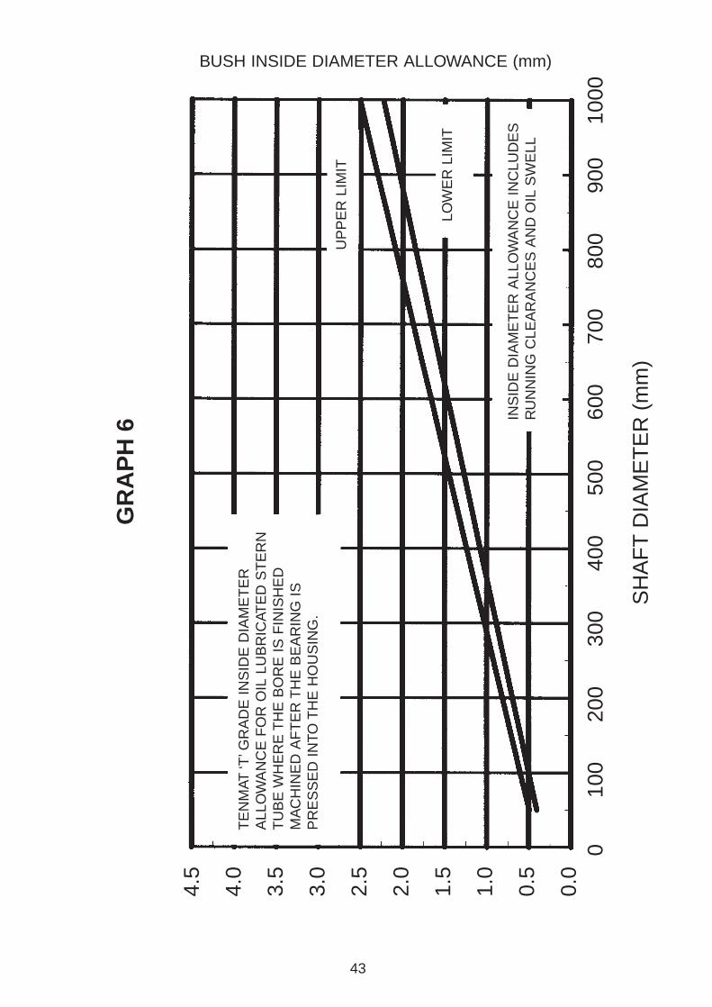
For semi-finished lubricated Stern Tube Bearings where the bore is finish machinedafter the bearing is pressed into the housing use Graphs 1 and 6.
For semi-finished and grease lubricated Rudder Bearings where the bore is finishmachined after the bearing is pressed into the housing, use Graphs 1 and 7.
17

(B) DIMENSIONING FROM FIRST PRINCIPLES
1) Interference Fit
FEROFORM bearings are usually retained in their housings by using an interferencefit.
Minimum recommended values are given on Graph 8 as are suggested achievablemanufacturing tolerances.
For oil lubricated and sometimes water lubricated propeller shaft bearings some formof additional mechanical fixing such as keys or locking strips is recommended.
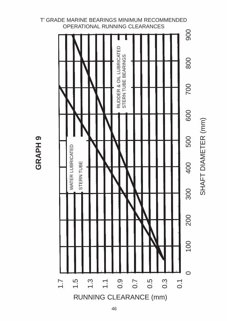
2) Running Clearance
Recommendations of bearing running clearance for a given shaft diameter areindicated on Graph 9. The amount of running clearance is critical to the performanceof a bearing.
Where applicable, such as rudder bearings, society regulations should be consultedwith respect to minimum running clearances.
3) Swell
Is a linear surface effect and not volumetric. We calculate swell as 0.5% x (OD-ID).
FEROFORM grades are stable in oil and greases.
In water the longitudinal (axial) swell of `T’ grades is 0.2%.
4) Bore Closure
Graph 10 indicates the optimum wall thickness and bore closure allowance to bemade when the wall thickness is greater than the optimum size. The wall willcompress by a certain percentage (shown on the graph) depending on how over thickit is.
Min wt = 0 05 d
18

5) Thermal ExpansionTABLE 3
Material Grade
F21/24F363F36F61F21
T11/T12/T14
6045411610050
2015138
10045
Normal toLaminaex 106/C
Parallel toLaminaex 106/C
The above data is typical for the materials up to their normal maximumoperating temperatures. T11/T12/T14 have a thermal contraction of20 x 10-6/°C on diameter (normal to laminae) from +20° to -70°C.
6) Lubrication Grooves
a) Water Lubrication
Multi-grooved configuration is generally adopted in plain bearings, oralternatively, stave construction for larger diameters.
See Groove Configuration on Page 14 for dimensions.
b) Oil Lubrication
Feed-in (washway) grooves are usually incorporated into oil lubricatedpropeller shaft bearing design to promote an hydro-dynamic fluid film.
See Groove Configuration on Page 16 for dimensions, note this is for thedesign of grooves only, suitable arrangements must be made for the free flowof heated oil out of the bearing area/system.
For those wishing to undertake `T’ grade rudder or propeller shaft bearingcalculations, a brief calculation procedure is shown below.
A more detailed method (for Industrial Bearings) is shown in TENMAT’sWearing and Bearing brochure. (Note dimensions are in millimetres).
Calculate Bearing Outside Diameter.
i. Add minimum interference fit from Graph 8 to maximum housing diameter = 0D min.
ii. Add machining tolerance to OD min = OD max
19

Calculate Bearing Inside Diameter.
i. Determine from Graph 9 the minimum Running Clearance for rudder or stern tube (or use Shipping Society recommendations) = RC min.
ii. Calculate swell allowance (in water) by:-
OD - ID x 0.005 = SA
50% swell allowance should be added to oil lubricated bearings in case of seal failure.
iii. Determine bore closure by calculating maximum interference.
I max = OD max - minimum housing
If wall is optimum or less than optimum thickness BCF = 1, but if wall is thicker than optimum determine Percentage Factor from Graph 11.That is if wall is twice optimum, then use 50% BCF.
Bore Closure = I max x BCF = BC
iv. Calculate Thermal Expansion for oil lubricated propeller shaft bearings (or if applicable for warm water applications) using Table 2.
Expansion = OD - ID x 50 x 10-6 x (65 - 20°C Temperature rise) = TE.
(NB 65 C is normal high temperature alarm setting).
v. Therefore ID machining size is given by - max shaft dia + RC min + SA + BC + TE = ID min.
ID max = ID min + Machining tolerance.
Calculate Bearing Length
Society rules generally state what length to shaft diameter may be used for particular vessel bearings, be they water or oil lubricated propeller shafts or rudder bearings. For non-society classed vessels, 2:1 L:D oil propeller shaft bearing ratios can be considered and typically 1 5 L:D oil propeller shaft bearings ratios can be considered and typically 1 25:1 L:D ratio for rudder bearings.
Calculate Grooving Configuration
Grooving configurations can be calculated using Table 2 and the Groove design drawings on Page 14.
20

BEARING CALCULATIONS - BY COMPUTER PROGRAMME
TENMAT offer the facility of `T’ grade Marine Bearing calculations byComputer, written in MS DOS GWBASIC for IBM compatible PC’s, for rudderbearings and oil, water or grease lubricated propeller shaft bearings.
Please consult TENMAT on [+44] (0)161 872 2181 or Approved Distributorsthroughout the world for details.
INFORMATION REQUIRED FROM THE USER
In order that we may offer advice on optimum FEROFORM grade, designconfiguration and dimensional fits etc, it would greatly assist us to have thefollowing information:
Type of Equipment:Specific Application:Speed: rpm or surface velocity if fully rotating/ cyclic speed if oscillating.Operational Temperature Range:Lubrication: If not sealed, recirculating system - condition of lubricant e.g.abrasive content, temperature.Operational Pressure (or load):Housing Diameter (min/max):Shaft Diameter (min/max):Length of Bearing:Preferred method of retention (if any): Interference, Mechanical, AdhesiveBonding.Preferred Method of fitting (if any) e.g.: Hydraulic Press, Freeze Fitting.Any additional related information or comment:
If replacing another material, details of any problems associated with thatmaterial or details of required improvements in performance etc would beuseful. For quotation purposes we would additionally need to know thequantity and whether the material is to be supplied fully finished (ready-to-fit)or semi-finished with allowances for on site finish machining (e.g. by shipyard).
21
RETENTION METHODS
Any conventional method of retention can be adopted with FEROFORM bearings such as:
Interference Fit
The level of interference required is given in Graph 8. This is the preferred method ofretention of a full configuration bearing since not only is installation quick and easy butadditional benefits are gained:
1. The recommended amount of interference fit should prevent either bearing rotation or axial movement. It is normal practice to additionally use an end keeper ring/shoulder as an additional safety precaution.
2. An interference fit provides intimate contact between the housing and bearing OD alleviating the possibilities of water ingress and thus preventing corrosion of the housing bore. Also bearing ovality that can occur in machined bushes is removed following
3. Experience has shown that a light film of ‘flushing’ oil is condusive on the OD for ease of fitting.
4. When a bearing is fitted with an interference there will be an associated amount of bore closure.
In the event of temperature decrease the resultant contraction will mean a loss of some ofthe interference (accounted for in the dimensioning calculation) which also means areduction of bore closure amount. This reduction of bore closure would normally increasethe ID but is approximately balanced by the thermal contraction effect. Thus the runningclearance remains roughly constant i.e. it will not significantly change with temperaturedecrease.
Mechanical
Traditionally used mechanical methods of retention can be used.
The methods should ensure that no rotational or axial movement is possible.
For example: To prevent rotation:-Anti-rotation key (for full bearings)Longitudinal keeper strip (for stave bearings)To prevent axial movement:-End keeper ring and forward stopFlange - locked by screwsStepped housing and end keeper ring
22

Bonding
1. Adhesive Bonding
FEROFORM bearings may alternatively be bonded into a housing. Bonding is notthe preferred method of retention since removal is made more difficult but may benecessary if:
i) The wall thickness is insufficient to allow retention by interference fit.
ii) To compensate for a corroded or out of round housing.
Our Technical Department can offer advice on adhesive selection. A two part, coldcure epoxy adhesive is normally acceptable. (see also no 3 & 4 below)
2. Using Chocking Compound
Epoxy chocking compounds (such as Chockfast Orange, Epocast or Belzona) can filllarge gaps and can be readily poured between housing and bearing; hencealignment can be easily achieved by positioning the bearing and then pouringchocking compound to fill the gap between bearing and housing.
Alternatively a dummy bearing the OD of which has been coated with mould releaseagent can be used during the pouring and curing operation.
When the chocking compound has fully cured, the dummy bearing can be removedand a finished FEROFORM bearing fitted by interference via freeze shrinking.
3. FEROFORM materials can be bonded together. For example, where two (or more)bearing sections need to be joined then the ends of each section can be machined with spigot/recess to a transition fit condition and a cold cure two part epoxy adhesive used. For additional security, radial holes can be drilled through the spigot join overlap and FEROFORM dowels be bonded and knocked into position.
4. Typical adhesives which can be employed are BOSTIK M890 and ARALDITE 2004.NOTE. Tenmat are NOT manufacturers of any adhesives. Therefore, users are recommended to follow the manufacturers recommendations.
23

MACHINING
1) Bearings
a) TURNING OD AND ID
RPM’s
FinishedDiameter
mminches
RPM 1400 1000 500 400 340 300 220 180 160
Upto502
Upto
1004
Upto
1506
Upto
2008
Upto
25010
Upto
30012
Upto
35014
Upto
40016
Upto
45018
NB If turning ring diameters from sheet use RPM x 2 with the same feed rates.
FEED RATES
Operation
OD + ID
Facing
Partinf off
Rough
0.4 mm/rev 0.2 mm/rev 0.1 mm/rev
0.1 mm/rev 0.08 mm/rev
0.08 mm/rev 0.05 mm/rev
0.25 mm/rev
0.1 mm/rev
SURFACE FINISH
Standard Fine
24
NB For machining of washways use OD + ID operation.
Stock Removal Rate
10mm on diameter (roughing)3mm on diameter (finishing)
TOOLING
Tungsten carbide is most often utilised with polycrystalline diamond tippedtooling used for large batch orders. For small quantities and one-off’s, HighSpeed Steel tooling is perfectly adequate. In all machining applications asharp cutting edge is of paramount importance and the grade of carbiderecommended is K10/K68 (ISO designation).
When turning large diameter or thin wall tubes a dummy centre should beused in the bore at the chuck jaw end to prevent the tube distorting, a tight fit‘bung’ or revolving centre is to be used at the tailstock end of the tube. Largediameter tubes can be supported with a suitable steady, however as steadies

may leave marks it may be desirable to have an allowance on OD to clean upafterwards.
Before finish cuts are applied the material should be left to cool to ambienttemperatures to allow for frictional heat generated in roughing out to bedissipated. Note the finish cut should be a minimum of 1mm to ensure thatcutting, rather than rubbing takes place.
Turning operations can be speeded up by approximately 50% if a coolant isused (i.e. water), but little improvement to the surface finish will result, onlyextended tool life.
Tooling Geometry for Turning and Boring
Turning
25
b) PART OFF
This can be done with the following tool angles.
Boring
SIDE PLAN END
= work piece
20°
30°
3° 20°
5°0.75 mm0.030”TIP RAD
5°
SIDE PLAN END
20°
30°
3°
20°
5°0.75 mm0.030”TIP RAD
5°
SIDE PLAN END5°
6°6°8°8°
7°

26
c) FACING
This can be done with the following tool angles.
d) MILLING
Again carbon tipped tooling should be used. When using side and face cuttersthe climb milling method should be employed, see below.
Side and Face Cutter
Width of Cut
0 - 12 mm 25 mm 600 0.6 mm/rev
0.5 mm/rev
0.25 mm/rev
0.15 mm/rev
450
350
300
20 mm
12 mm
6 mm
12 - 25 mm
25 - 40 mm
40 - 50 mm
Max Depth of Cut Speed (RPM) Feed
Typical Data using 200mm Diameter Cutters with 12 Tips
Directionof cut
Direction of feed
Facing
SIDE PLAN END
5° 5°
3°
5°
5°5°
Cutter
27
OD of Cutter
75 mm 75 mm 300 0.4 mm/rev
0.25 mm/rev25075 mm100 mm
Width of Cut Speed (RPM) Feed
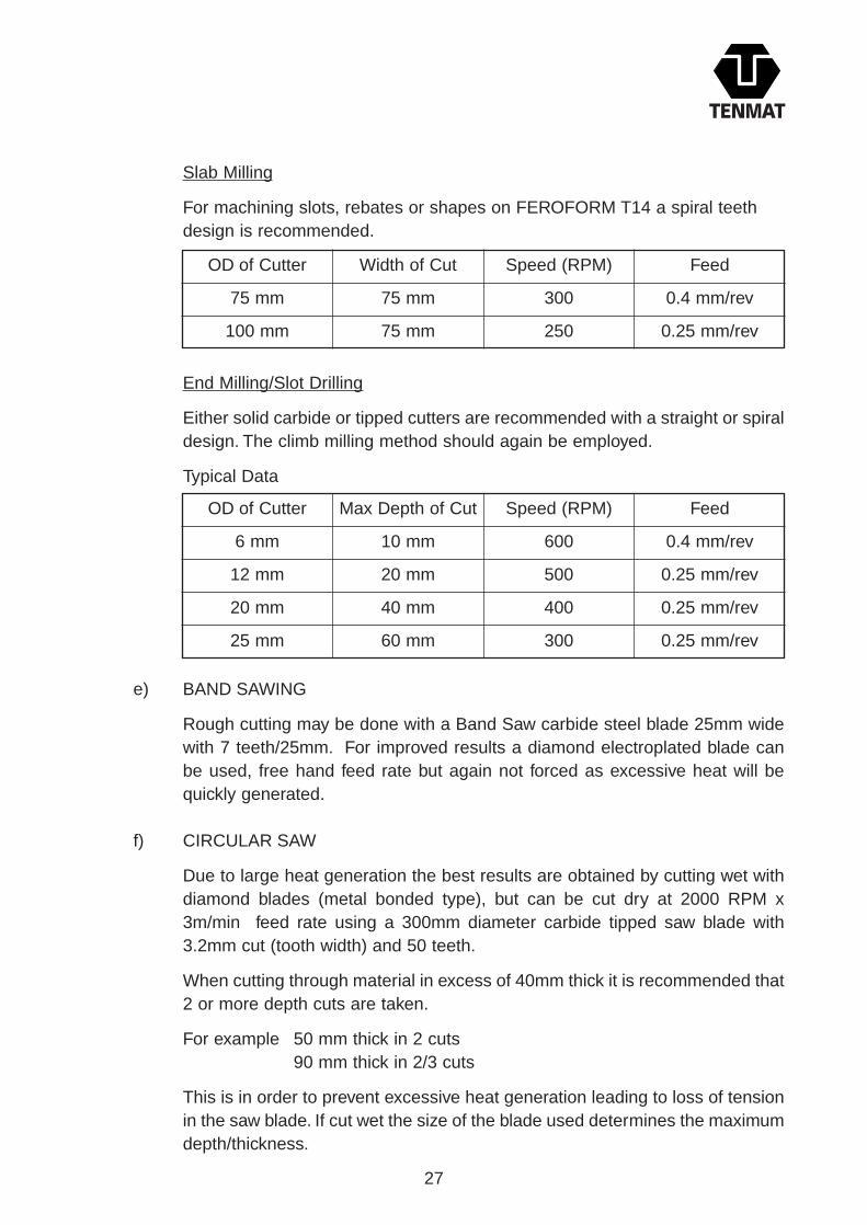
Slab Milling
For machining slots, rebates or shapes on FEROFORM T14 a spiral teethdesign is recommended.
End Milling/Slot Drilling
Either solid carbide or tipped cutters are recommended with a straight or spiraldesign. The climb milling method should again be employed.
Typical Data
OD of Cutter
6 mm 10 mm 600 0.4 mm/rev
0.25 mm/rev
0.25 mm/rev
0.25 mm/rev
500
400
300
20 mm
40 mm
60 mm
12 mm
20 mm
25 mm
Max Depth of Cut Speed (RPM) Feed
e) BAND SAWING
Rough cutting may be done with a Band Saw carbide steel blade 25mm widewith 7 teeth/25mm. For improved results a diamond electroplated blade canbe used, free hand feed rate but again not forced as excessive heat will bequickly generated.
f) CIRCULAR SAW
Due to large heat generation the best results are obtained by cutting wet withdiamond blades (metal bonded type), but can be cut dry at 2000 RPM x3m/min feed rate using a 300mm diameter carbide tipped saw blade with3.2mm cut (tooth width) and 50 teeth.
When cutting through material in excess of 40mm thick it is recommended that2 or more depth cuts are taken.
For example 50 mm thick in 2 cuts 90 mm thick in 2/3 cuts
This is in order to prevent excessive heat generation leading to loss of tensionin the saw blade. If cut wet the size of the blade used determines the maximumdepth/thickness.

28
g) DRILLING
Carbide tipped or masonry drills are recommended but high speed steel drillscan also be used for small batch work.
Typical Data
NB Drills with a standard helix spirl are to be used and these must becontinually cleared/pecked.
h) GROOVING
For example Bush size: 500mm OD x 450mm ID x 600mm long with 25mmslots through bore 12mm deep.
Machining of Longitudinal Grooves in Feroform
Drill Size
3 mm 800 1 mm/sec
1.25 mm/sec
1 mm/sec
0.75 mm/sec
0.6 mm/sec
0.4 mm/sec
700
600
400
250
200
6 mm
12 mm
19 mm
25 mm
38 mm
Speed (RPM) Feed
Recommended
MACHINE - Verticalbored right angle head
Shaper Lathe
As forshaping
As forshaping
As for 1
Specially extended tool bar at 660mm long with carbide tip welded to90°. Tip to have maximum 5°clearance on all sides. Improvisedworkholding required.
0.5 mm - 1 mm (0.02” to 0.04”) perstroke
Stroke rate 9.5 m/min
TOOLING - Spiral flutedrill (carbide tipped)
DEPTH OF CUT - Up to6.4 mm (1/2”) deep perpass
SPINDLE SPEED -500 rpm
FEED RATE -0.25 mm/rev
Alt 1 Alt 2
IMPORTANT: Wherever possible, final bore after grooving to improve results(stock removal of 0.5mm total).

29
If cannot disengage spindle drive from feed
Lathe
Using steel “running” bearing as steady gripped in chuck with its’ boremachined to suit OD of bearing being grooved.
Graduations on chuck to equispace grooves if can disengage spindle, if notmark each bearing.
Grease must be applied to the OD of the bearing running in the steel checkring to prevent over heating.
Engage feed traverse, forward then reverse, taking depth cuts as per shapingdetail until desired depth is achieved. Obviously if it is possible to disengagethe spindle rev’s still use feed and the need for a `running’ bearing disappears.
Axial Grooves
For tooling angles see below and for typical speeds and feeds see shapinginformation.
Sketch B
Use steady to lock up or clamp bearing
Boring Bar
Lathe Bed
SIDE PLAN END
7° 8° 8° 6°6°
3°

30
Right-angle Head
Minimum ID approximately 250mm.
Supplier: Centreline Machine Tool Company, Leicestershire. Kennametal Bristol Erikson), Bristol.
Spiral Grooving
This should be done with the following tool angle.
It is recommended that internal spiral grooving be done using a right anglehead attachment to a vertical borer machine with a spiral/straight slot drill.
See end milling/slot drilling for speed/feed/depth of cut data.
Spiral grooving with a single point tool can be carried out on a lathe but greatcare must be taken to ensure a keen, sharp cutting edge is used along withsmall depth cuts.
For example - 12mm wide groove on a lathe in a 150mm ID.
Cutter Details - See sketch above.Spindle Speed - 50 rpm.Depth of Cut per pass - 0.25mm.Pitch - 100mm.
Spiral grooving using Power Driven `live tooling’ on a lathe results in a goodquality groove achieved in half the time. An adapted thread grinding latheattachment is suitable.
SIDE PLAN END
25°
15° 15° 15°15°
3°

31
i) HACK SAWING
The FEROFORM `T’ grades can be easily cut using a hacksaw with apreferred blade range of 10 to 18 teeth per 25mm.
j) TAPPING
This can be carried out using a normal tap wrench or a radial arm drill with`HAND TAP’ selected.
For example: 80 rpm for 10mm Whitworth.
Please note with drilled or tapped holes clearance should be allowed for at thebottom of the hole or thread to prevent excessive delaminating forces causedby inserts, bolts etc.
k) PLANING
FEROFORM `T’ grades can be hand or power planed with results dependentupon operator skill. Surform type hand planes may give better results. Whenmanually planing a standard wood plane with a very sharp edge should beused. For power planing spindle speeds should be 20,000 rpm, stock removalno more than 0.8mm per pass and solid carbide blades used. Power planingis obviously the recommended method.
l) SHAPING
Shaping operations can be carried out on FEROFORM grades but whereverpossible an `intermittent’ cutting alternative is recommended.
Tooling clearances should be as for turning of axial grooves on Page 29.
Typical Data
Width of Tool
3 mm 1 mm 96 st/min 130 mm
380 mm
600 mm
600 mm
46 st/min
33 st/min
17 st/min
0.5 mm
0.25 mm
0.25 mm
10 mm
16 mm
25 mm
Depth of Cut(per stroke)
Stroke Rate Length

32
Conversion Table
Metric (mm)
0.05
0.10
0.15
0.20
0.25
0.40
0.50
0.60
0.75
1.00
Imperial (inches)
0.002
0.004
0.006
0.008
0.010
0.015
0.020
0.025
0.030
0.040
2) STAVES
Cutter Design for Concave Profile
When opposing flat blades are placed at diametrically opposite angles from 180 ,they result in a machined radius.
Typical speeds and feeds are 400 rpm @ 500mm per min with 1.5mm stock removal.Cutting blades are high speed steel (for small batches) or solid carbide/carbidetipped (for larger batches). Clearance from cutting edge is 15-20°.
Convex Profiles
Same cutter body to be used but all blades must be ground to the correct radius.
Cutting Blade
Main body buttercan be Mild Steel.Bore to suit MillingArbour Diameter

33
3) SHEETS
Sanding
`T’ grades can be sanded or wet ground to thickness (wet grinding results in improvedfinish).
Typical Data
Sanding*
Belt Grit Stock ApproxSize Removal Feed Rate Surface Finish
P36 0 25mm per pass 3 metre/min 12 µmP80 0 12mm per pass 5 metre/min 6 µm
Wet Grinding*
Stone Stock ApproxGrit Size Removal Feed Rate Surface Finish
36 0.25mm per pass 3 metre/min 1 µm
* Machines used were “Grindmaster” sander with 900mm wide belt (Machine built byEllesco’s) and “Rowlands” wet “duplex” grinder.
4) HAND FINISHING
Filing
FEROFORM `T’ grades can easily be filed using a medium grade file which is in goodcondition.
Emery Cloth
The use of emery paper can improve the surface finish particularly if `wet and dry’ upto 400 grit is used.
Surforming
This has been shown to be an extremely good method of bulk material removal forroughing of FEROFORM.

34
5) REMOVAL OF DUST AND SWARF
It is essential that good housekeeping is maintained on all machines and locallegislation is adhered to.
Swarf generated from cutting of staves is much finer (chip broken) and thereforeeasier to extract as it is being generated. Swarf from continuous contact cuttingoperations, i.e. shaping and turning needs to be bagged off at the machine with caretaken not to allow the turnings to clog up any extraction equipment used.
Safety, Handling and Storage
See FEROFORM Product Data Sheet.
35
FITTING METHODS
Press Fitting
It is recommended that bearings to be fitted by pressing have an entry chamfer to facilitatestarting.
Once started, pressing should be a continuous operation until fully installed since, ifstopped, re-starting may require extra pressing force.
The housing should be round, with a truly parallel bore, clean and grease free.
The graph indicates the nominal fitting force for T14. It is based on optimum wall thicknessand 2:1 R:d ratio. For L:d ratios over 2:1, higher forces than those indicated can beexpected.
NOTE Bearings may be supplied in more than one piece. Since water lubricated bearingshave longitudinal grooves in the base it is important to ensure that grooves line up.To assist,a keeper bar placed in a groove will help.
It is suggested that an annular groove is machined into one end of each length of a multi-piece bearing to facilitate flow of water through the bearing even if the grooves are not fullyaligned.
The annular groove should be to the same depth as the longitudinal grooves.
Freeze Fitting
FEROFORM bearings can be shrink fitted by freezing in either dry ice (solid CO2) or liquidnitrogen.
In both cases extreme care should be taken since:-
1.The extremely low temperature of these products can cause severe burns or frostbite.
2.Gassing off of these products displaces air leading to possible asphyxiation unlessadequate ventilation is supplied.
If this method of freeze fitting is used manufacturer’s guidance notes must be followed.
The temperature of dry ice is -79°C and liquid nitrogen is -196°C.
The freeze down time for FEROFORM bearings is shown in Table on page 36.

36
Once frozen they can be slid into the housing without any difficulty i.e. the amount ofshrinkage will be greater than the amount of interference.
These are typical times for guidance only, and will vary due to ambient conditions, wallthickness, bearing diameter etc.
On warming back to room temperature the interference fit will be sufficient to hold thebearing in place but normally, for added safety, a forward stop and an end keeper ring issuggested.
For large bearings supplied in more than one piece care should be taken to align thegrooves.
This is quite easy when freeze fitting but it is recommended that each piece be allowed towarm and secure before installing subsequent pieces.
When freeze fitting staves it is important to ensure that each stave is covered with thecooling medium otherwise some may not fully shrink.
Freeze fitting can be used with all stave constructed bearings whether secured byinterference fit utilising a longitudinal keeper strip or when fitting dovetailed staves into adovetailed housing.
Adhesive Bonding
The adhesive manufacturers instructions must be followed. In general terms both housingbore and bearing OD should be clean and grease free.
The machined finish of the housing and bearing will provide adequate mechanical keyingwhich further improves the adhesive bond.
Since no interference is involved there should be a clearance between the OD of thebearing and the housing bore.
The required clearance varies according to the adhesive used and therefore the adhesivesuppliers recommendations should be sought.
Similarly cure times vary; for example a cold cure, two part epoxy may take 6-8 hours toharden and up to 48 hours to achieve full strength at normal ambient temperatures.
LiquidNitrogen
FreezingDown Time
Warming UpTime
1/2 hour 11/2 hour
11/2 hour21/2 hour
Dry Ice

37
APPROVALS
Classification Societies approve FEROFORM T grades for the following:
• Oil lubricated (sealed system) stern tube/propeller shaft bearing.
• Water lubricated (open system) stern tube/propeller shaft bearings.
• Grease lubricated propeller shaft bearings.
• Grease, water or oil lubricated rudder bearings.
Notes
Allowable pressures and L:D ratios vary slightly between Societies. Permitted runningclearances also vary slightly and for this reason the TENMAT recommendations quoted areminimum allowable values.
Societies Having Approved FEROFORM include:
• Lloyds Register of Shipping
• American Bureau of Shipping
• Det Norske Veritas
• Bureau Veritas
• Germanischer Lloyd
• Nippon Kaiji Kyokai
• Korean Register of Shipping
• Biro Klasifikasi Indonesia
• China Classification Society
• China Corporation Register of Shipping
• Registro Italiano Navale
The information herein is presented in good faith, but TENMAT does not warrant theconformity of its materials to the listed properties or the suitability of its materials for anyparticular purpose. In the event of any uncertainty regarding suitability for any application,please contact Tenmat and ask for our Technical Services Department on [+44] (0)161872 2181.

1.4
1.2 1
0.8
0.6
0.4
0.2 0
0
200
400
600
800
1000
1200
100
300
500
70
0
90
0
110
0
GR
AP
H 1
TE
NM
AT
“T
”G
RA
DE
INT
ER
FE
RE
NC
E
INTERFERENCE
HO
US
ING
DIA
ME
TE
R (
mm
)
Rec
omm
ende
d M
ax I
nter
fere
nce
(Inc
ludi
ng M
achi
ning
Tol
eran
ce
Rec
omm
ende
d M
ax I
nter
fere
nce
(Inc
ludi
ng M
achi
ning
Tol
eran
ce
38

0
100
200
30
0
4
00
500
600
70
0
8
00
900
1000
SH
AF
TD
IAM
ET
ER
(mm
)
4.5
4.0
3.5
3.0
2.5
2.0
1.5
1.0
0.5
BUSH INSIDE DIAMETER ALLOWANCE (mm)
TE
NM
AT ‘T
’GR
AD
E I
NS
IDE
DIA
ME
TE
RA
LLO
WA
NC
E F
OR
WAT
ER
LU
BR
ICAT
ED
ST
ER
N T
UB
E A
ND
BR
AC
KE
T B
EA
RIN
GS
,W
HIC
H A
RE
PR
ES
SE
D I
NTO
TH
EH
OU
SIN
G W
ITH
OU
T F
UR
TH
ER
MA
CH
ININ
G.
INS
IDE
DIA
ME
TE
R A
LLO
WA
NC
E I
NC
LUD
ES
RU
NN
ING
CLE
AR
AN
CE
S, W
ATE
R S
WE
LL A
ND
BO
RE
CLO
SU
RE
, B
AS
ED
ON
OP
TIM
UM
WA
LLT
HIC
KN
ES
S O
F [
(0.0
625
X S
HA
FT
DIA
)+2.
5MM
]
UP
PE
R L
IMIT
LOW
ER
LIM
IT
GR
AP
H2
39

0
100
200
30
0
4
00
500
600
70
0
8
00
900
1000
SH
AF
TD
IAM
ET
ER
(mm
)
4.5
4.0
3.5
3.0
2.5
2.0
1.5
1.0
0.5
0.0
BUSH INSIDE DIAMETER ALLOWANCE (mm)
TE
NM
AT ‘T
’GR
AD
E I
NS
IDE
DIA
ME
TE
RA
LLO
WA
NC
E F
OR
OIL
LU
BR
ICAT
ED
ST
ER
NT
UB
E W
HIC
H A
RE
PR
ES
SE
D I
NTO
TH
EH
OU
SIN
G W
ITH
OU
T F
UR
TH
ER
MA
CH
ININ
G.
INS
IDE
DIA
ME
TE
R A
LLO
WA
NC
E I
NC
LUD
ES
RU
NN
ING
CLE
AR
AN
CE
S,
OIL
SW
ELL
AN
D
BO
RE
CLO
SU
RE
,B
AS
ED
ON
OP
TIM
UM
WA
LL T
HIC
KN
ES
S O
F[(
0.06
25 X
SH
AF
T D
IA)+
2.5M
M]
UP
PE
R L
IMIT LO
WE
R L
IMIT
GR
AP
H3
40

0
100
200
30
0
4
00
500
600
70
0
8
00
900
1000
SH
AF
TD
IAM
ET
ER
(mm
)
4.5
4.0
3.5
3.0
2.5
2.0
1.5
1.0
0.5
0.0
BUSH INSIDE DIAMETER ALLOWANCE (mm)
TE
NM
AT ‘T
’GR
AD
E I
NS
IDE
DIA
ME
TE
RA
LLO
WA
NC
E F
OR
WAT
ER
AN
D G
RE
AS
ELU
BR
ICAT
ED
ST
ER
N T
UB
E W
HIC
H A
RE
PR
ES
SE
D I
NTO
TH
E H
OU
SIN
G W
ITH
OU
TF
UR
TH
ER
MA
CH
ININ
G.
INS
IDE
DIA
ME
TE
R A
LLO
WA
NC
E I
NC
LUD
ES
RU
NN
ING
CLE
AR
AN
CE
S,
SW
ELL
AN
D B
OR
E C
LOS
UR
E,
BA
SE
D O
N O
PT
IMU
M W
ALL
TH
ICK
NE
SS
OF
[(0
.062
5 X
SH
AF
T D
IA)+
2.5M
M]
UP
PE
R L
IMIT
LOW
ER
LIM
IT
GR
AP
H4
41

0
100
200
30
0
4
00
500
600
70
0
8
00
900
1000
SH
AF
TD
IAM
ET
ER
(mm
)
4.5
4.0
3.5
3.0
2.5
2.0
1.5
1.0
0.5
0.0
BUSH INSIDE DIAMETER ALLOWANCE (mm)
TE
NM
AT ‘T
’GR
AD
E I
NS
IDE
DIA
ME
TE
RA
LLO
WA
NC
E F
OR
WAT
ER
LU
BR
ICAT
ED
ST
ER
N T
UB
E A
ND
BR
AC
KE
T B
EA
RIN
GS
WH
ER
E T
HE
BO
RE
IS
FIN
ISH
ED
MA
CH
INE
DA
FT
ER
TH
E B
EA
RIN
G I
S P
RE
SS
ED
IN
TOT
HE
HO
US
ING
.
INS
IDE
DIA
ME
TE
R A
LLO
WA
NC
E I
NC
LUD
ES
RU
NN
ING
CLE
AR
AN
CE
S A
ND
WAT
ER
SW
ELL
UP
PE
R L
IMIT
LOW
ER
LIM
IT
GR
AP
H5
42
0
100
200
30
0
4
00
500
600
70
0
8
00
900
1000
SH
AF
TD
IAM
ET
ER
(mm
)
4.5
4.0
3.5
3.0
2.5
2.0
1.5
1.0
0.5
0.0
BUSH INSIDE DIAMETER ALLOWANCE (mm)
TE
NM
AT ‘T
’GR
AD
E I
NS
IDE
DIA
ME
TE
RA
LLO
WA
NC
E F
OR
OIL
LU
BR
ICAT
ED
ST
ER
NT
UB
E W
HE
RE
TH
E B
OR
E I
S F
INIS
HE
DM
AC
HIN
ED
AF
TE
R T
HE
BE
AR
ING
IS
PR
ES
SE
D I
NTO
TH
E H
OU
SIN
G.
INS
IDE
DIA
ME
TE
R A
LLO
WA
NC
E I
NC
LUD
ES
RU
NN
ING
CLE
AR
AN
CE
S A
ND
OIL
SW
ELL
UP
PE
R L
IMIT
LOW
ER
LIM
IT
GR
AP
H6
43

0
100
200
30
0
4
00
500
600
70
0
8
00
900
1000
SH
AF
TD
IAM
ET
ER
(mm
)
4.5
4.0
3.5
3.0
2.5
2.0
1.5
1.0
0.5
0.0
BUSH INSIDE DIAMETER ALLOWANCE (mm)
TE
NM
AT ‘T
’GR
AD
E I
NS
IDE
DIA
ME
TE
RA
LLO
WA
NC
E F
OR
WAT
ER
& G
RE
AS
ELU
BR
ICAT
ED
RU
DD
ER
BE
AR
ING
S W
HE
RE
TH
E B
OR
E I
S F
INIS
HE
D M
AC
HIN
ED
AF
TE
RT
HE
BE
AR
ING
IS
PR
ES
SE
D I
NTO
TH
EH
OU
SIN
G.
INS
IDE
DIA
ME
TE
R A
LLO
WA
NC
E I
NC
LUD
ES
RU
NN
ING
CLE
AR
AN
CE
S A
ND
OIL
SW
ELL
UP
PE
R L
IMIT
LOW
ER
LIM
IT
GR
AP
H7
44

0
100
200
30
0
4
00
500
6
00
700
8
00
900
10
00
1100
120
0
HO
US
ING
DIA
ME
TE
R(m
m)
1.2
1.1
1.0
0.9
0.8
0.7
0.6
0.5
0.4
0.3
0.2
0.1
0.0
INTERFERENCE & MACHINING (mm)
RE
CO
MM
EN
DE
D M
INIM
UM
IN
TE
RF
ER
EN
CE
SU
GG
ES
TE
D M
AC
HIN
ING
TO
LER
AN
CE
S
GR
AP
H8
INT
ER
FE
RE
NC
E F
IT A
ND
MA
CH
ININ
G T
OL
ER
AN
CE
S ‘T
’GR
AD
ES
ON
LY
45
0
10
0
200
30
0
400
50
0
600
70
0
800
9
00
SH
AF
TD
IAM
ET
ER
(mm
)
RUNNING CLEARANCE (mm)
1.7
1.5
1.3
1.1
0.9
0.7
0.5
0.3
0.1
T’ GRADE MARINE BEARINGS MINIMUM RECOMMENDEDOPERATIONAL RUNNING CLEARANCES
WAT
ER
LU
BR
ICAT
ED
ST
ER
N T
UB
E
RU
DD
ER
&O
IL L
UB
RIC
ATE
DS
TE
RN
TU
BE
BE
AR
ING
S
GR
AP
H9
46

MA
XIM
UM
RE
CO
MM
EN
DE
D W
AL
L T
HIC
KN
ES
SW
AL
L T
HIC
KN
ES
S (
mm
)
GR
AP
H10
OP
TIM
UM
WA
LL T
HIC
KN
ES
S F
OR
BE
AR
ING
SW
ITH
GR
OO
VE
S I
S 0
,062
5 d+
2.5
mm
.F
OR
BE
AR
ING
S W
HE
RE
GR
OO
VE
S A
RE
NO
TR
EQ
UIR
ED
, TH
E M
INIM
UM
RE
CO
MM
EN
DE
DW
ALL
TH
ICK
NE
SS
IS
0.0
5 d.
SH
AF
TD
IAM
ET
ER
2.5
min
➔
➔
110%
MIN
IMU
M W
AL
L T
HIC
KN
ES
S F
OR
BE
AR
ING
S W
ITH
NO
GR
OO
VE
S
100%
RE
CO
MM
EN
DE
D (
OP
TIM
UM
) WA
LL
TH
ICK
NE
SS
FO
R B
EA
RIN
GS
WIT
H G
RO
OV
ES BO
RE
CL
OS
UR
E F
AC
TOR
90%
80%
70%
60%
50%
100
200
300
400
500
600
700
800
900
0
10
20
3
0
40
50
6
0
70
80
90
100
11
0
1
20
1
30
47
BORE CLOSURE