Design guidelines - Batelaan Kunststoffen B.V. · Design guidelines for the thermoforming process...
90
Design guidelines for the thermoforming process 1 1 Design guidelines for product engineers on the thermoforming process U aangeboden door: Batelaan Kunststoffen BV ● Veerpolder 8 ● 2361KV Warmond T: 071-5613301 ● F: 071-5616701 ● www.batelaan.nl Zonder schriftelijke toestemming van de ProducentenVereniging Thermoplasten (PVT) mag niets uit deze informatiemap worden verveelvoudigd en/of openbaar gemaakt door middel van druk, fotokopie, microfilm of anderszins, hetgeen ook van toepassing is op de gehele of gedeeltelijke bewerking. Deze informatiemap is gebaseerd op de trainingmodules, gerealiseerd in het kader van T-ForM. Voor de eventuele aanwezigheid van (zet)fouten en onvolledigheden kan de PVT geen aansprakelijkheid aanvaarden. PVT, Postbus 420, 2260 AK Leidschendam, [email protected] www.t-form.eu July 2008
Transcript of Design guidelines - Batelaan Kunststoffen B.V. · Design guidelines for the thermoforming process...

Design guidelines for the thermoforming process 1
1
Design guidelines for product engineers
on the thermoforming process
U aangeboden door:
Batelaan Kunststoffen BV ● Veerpolder 8 ● 2361KV Warmond
T: 071-5613301 ● F: 071-5616701 ● www.batelaan.nl
Zonder schriftelijke toestemming van de ProducentenVereniging Thermoplasten (PVT) mag niets uit deze
informatiemap worden verveelvoudigd en/of openbaar gemaakt door middel van druk, fotokopie, microfilm of
anderszins, hetgeen ook van toepassing is op de gehele of gedeeltelijke bewerking.
Deze informatiemap is gebaseerd op de trainingmodules, gerealiseerd in het kader van T-ForM. Voor de
eventuele aanwezigheid van (zet)fouten en onvolledigheden kan de PVT geen aansprakelijkheid aanvaarden.
PVT, Postbus 420, 2260 AK Leidschendam, [email protected]
www.t-form.eu
July 2008

Design guidelines for the thermoforming process 2
2
Contents
Contents ................................................................................................................................ 1
1. Executive Summary ........................................................................................................... 5
2. Introduction ........................................................................................................................ 9
2.1 Thin Sheet Thermoforming ........................................................................................... 9
2.2 Thick Sheet Thermoforming ....................................................................................... 10
2.3 Tooling ....................................................................................................................... 10
2.4 Literature .................................................................................................................... 11
3. Thermoforming process ................................................................................................... 15
3.1 Bubble Forming .......................................................................................................... 15
3.2 Cavity Forming ........................................................................................................... 15
3.3 Drape Forming ........................................................................................................... 17
3.4 Variations to Avoid Excessive Thinning ..................................................................... 18
3.4.1 Cavity Forming with Plug Assistance ................................................................... 18
3.4.2 Billow Drape Forming ........................................................................................... 19
3.4.3 Snap-Back Forming ............................................................................................. 19
3.4.4 Reverse Draw with Plug-Assist Forming .............................................................. 19
3.4.5 Twin Sheet Forming ............................................................................................. 19
3.4.6 Other Techniques ................................................................................................ 21
4. Tooling ............................................................................................................................. 23
4.1 Tooling Costs: Thermoforming versus Injection Moulding ........................................... 23
4.2 Tooling: Design Considerations .................................................................................. 23
4.2.1 Thermoforming Mould Design Criteria .................................................................. 24
4.3 Heat Transfer Considerations ..................................................................................... 26
4.3.1 Mould Temperature Control .............................................................................. 27
4.4 Tooling Materials ........................................................................................................ 27
4.1.1 Wood ................................................................................................................... 30
4.4.2 Plaster ................................................................................................................. 30
4.4.3 Sprayed Metal Alloys ........................................................................................... 31
4.4.4 Resin Tooling ....................................................................................................... 31
4.4.5 Aluminium ............................................................................................................ 33
4.4.6 Steel .................................................................................................................... 33
4.4.7 Russian Tooling Practice ..................................................................................... 33
5. Proprietary resins and resin based materials for tooling ................................................... 37
5.1 Axson EPO 4042 EPO4042/L Epoxy Casting Resin ................................................... 37
5.2 Epon Epoxy Resins .................................................................................................... 37
5.3 Fablite ........................................................................................................................ 38

Design guidelines for the thermoforming process 3
3
5.4 Polylite Polyester Resin .............................................................................................. 38
5.5 Metapor Epoxy/Aluminium .......................................................................................... 38
5.6 Espor .......................................................................................................................... 40
5.7 Vestalloy ..................................................................................................................... 40
5.8 WIS Tooling ................................................................................................................ 41
5.9 Albright RT ................................................................................................................. 41
5.10 Poly Steel ................................................................................................................. 41
5.11 Microsyn ................................................................................................................... 41
5.12 Ren-Shape (Vantico) ................................................................................................ 42
5.13 Polyurethane Machinable Slab (Ureol Board Axson) ................................................ 43
5.14 Epoxy / Aluminium using Stereolithography (Escuelo Technica)............................... 43
5.15 Miscellaneous Materials ........................................................................................... 43
6. Tooling: plug assistance................................................................................................... 47
6.1 Plug Assisted Thermoforming ..................................................................................... 47
6.2 Plug Materials............................................................................................................. 49
6.2.1 Acetal (e.g. Delrin) ............................................................................................... 52
6.2.2 Hardened Felt ...................................................................................................... 52
6.2.3 Syntactic foam ..................................................................................................... 52
6.2.4 Wood ................................................................................................................... 52
6.2.5 Resins .................................................................................................................. 52
6.2.6 “Hytac” Syntactic foams ....................................................................................... 52
6.3 Friction Between Plug and Sheet................................................................................ 54
6.4 Mould Plug and Heat Transfer .................................................................................... 62
6.5 Plug Assisted Forming Experimental Work ................................................................. 62
7. Computerised process simulation .................................................................................... 67
7.1 Background ................................................................................................................ 67
7.2 Forming feometries..................................................................................................... 70
7.3 Computer simulation literature summary .................................................................... 71
8. References ...................................................................................................................... 77
Appendix .............................................................................................................................. 80
Planoxal-50 Aluminium Data Sheet .................................................................................. 81
RenShape® BM 5055 ..................................................................................................... 83
EPO 4042 / EPO 4042/L .................................................................................................. 85
LAB 1001 ......................................................................................................................... 87
PROLAB 65...................................................................................................................... 89

Design guidelines for the thermoforming process 4
4

Design guidelines for the thermoforming process 5
5
1. Executive Summary
This report reviews the choices that may be considered for thermoforming processing.
Thermoforming is a broad technology genre so the report gives some background
information to the various thermoforming process sub groups and links the tooling
considerations to these technologies. The tooling options for high pressure plug assisted,
moulding which is a significant subgroup, is also discussed in some detail.
This report considers the factors deemed to be important when selecting materials for the
construction of moulds for the thermoforming process. It does not consider design issues
such as draft angles, corner radii and draw ratios because these should have been
addressed during product design.
The selection of mould materials is dependent on several factors including cost, quantity
and quality of parts required the capability and lead time of the toolmaker and the thermal
characteristics of the material.
Additionally to comply with the dimensional and thermal requirements of the
thermoforming process other tooling material requirements need careful consideration.
The material must be capable of thermal cycling, be able to transmit vacuum from all
areas of its surface, be robust but easily modifiable and be dimensionally accurate with
known shrinkage characteristics.
The literature confirms that aluminium is the mould material of choice for high volume
production work, meeting all of the characteristics outlined above. The material is readily
available, easily worked integrating into CAD/CAM systems and is relatively cheap.
Importantly it also offers excellent thermal conductivity: moulds are a fundamental part of
the heat transfer process in thermoforming and determine the consistency of the
mouldings from both a dimensional and quality perspective. Heat transfer characteristics
maximises the efficiency of the production cycle and once the economics of scale become
favourable it this characteristic that confirms on aluminium its dominant status.
For prototype or low volume application other materials become worthy of consideration.
In addition to the ubiquitous aluminium these can include resin (including metal filled
systems) syntactic foam, composite board, plaster, and wood. Prototype moulds and
moulds for low volume applications are usually fabricated from more easily worked
materials where the heat transfer benefits of aluminium associated can become
secondary considerations. Data sheets for aluminium suitable for thermoforming tooling
have been identified but none of the major suppliers make a point of supplying grades
specifically for thermoforming.

Design guidelines for the thermoforming process 6
6
Two non-aluminium materials were investigated; filled epoxy resin systems and
machinable polyurethane board. These materials are indicated for several applications of
which thermoforming tooling is only one. Specific information linking the material to
thermoforming is therefore limited, but data sheets for these types of materials used by
the consortium partners have been reviewed
Finally in the course of the study the literature unearthed a series of articles that linked
thermoforming and tooling materials to process simulation. A brief synopsis of this area is
included for completion.

Design guidelines for the thermoforming process 7
7

Design guidelines for the thermoforming process 8
8

Design guidelines for the thermoforming process 9
9
2. Introduction
Thermoforming usually describes a process whereby a thermoplastic sheet is heated
sufficiently to soften it and then cooled to become solid again after forming to the required
shape. Wagenknecht(1) stated that technical terminology has not been standardised, and
different terms are used for the same thing, e.g. thermoforming, vacuum forming, heat
forming and deep drawing can often be interchanged. The VDI recommended description
was “shaping of sheets of thermoplastics materials”, and the process was defined as
“stretch forming in which the heated firmly clamped blank is stretched. During stretching
the wall thickness of the blank is reduced”.
However, the process is not restricted to sheet but can for example, be used for joining
pipes by forming sockets and for making power cable spacers by winding preheated
plastic rods around formers. Thermoforming can involve bending and folding sheet
following localised heating, free forming by inflation without moulds and draping heated
sheets over jigs. However, most thermoforming involves shaping extruded sheet with
moulds using vacuum or compressed air or a combination of the two and this review is
concerned with the tooling used for this process.
Thermoforming with moulds can be divided into two quite distinct processes, which are
also defined mainly by two product areas:
1. Single-trip packaging using thin gauge sheet of 1.5 mm or less which can be used off
rolls, heated, formed and cooled very quickly.
2. Durable products such as door panels, caravan roofs etc. using 3 mm or thicker precut
extruded sheet which can take relatively long times to heat up and cool down in the
thermoforming process.
2.1 Thin Sheet Thermoforming
Thin sheet thermoforming can produce very high output rates of thin wall containers, due
to high area utilisation and in some cases involve forming with the extrusion. Economies
result from immediate recycling of skeletal waste and trimmings with the extrusion edge
trim. Coextrusion of barrier sheet and form-fill seal processes within a multistation
machine are possible(2). Unlike injection moulding, wall thicknesses will be variable but
providing these are kept within reasonable limits, particularly with barrier sheet, then this
is adequate for most single trip short life applications.
Design guidelines for the thermoforming process 10
10
With thin sheet, heating and cooling can be rapid, area to thickness ratio can be much
higher than with injection moulding, and trimming can be in-situ. A single machine with roll
feed and comparatively low cost tooling can easily outperform injection moulding, but very
importantly the trend towards multilayer barrier packaging for long shelf life normally
eliminates injection moulding.
2.2 Thick Sheet Thermoforming
In comparison to injection moulding, manufacturing costs for thick sheet forming are high
due to extruded sheet being the starting material and long cycle times resulting from long
heating and cooling times. Furthermore, there is the trimming of thick sheet after forming.
However, thermoforming can compete with injection moulding for products where low
tooling costs make low production volumes economic, short tooling lead times are
important and very large areas are needed. In principle, size is limited only by the width of
available extruded sheet. The process is ideal for products such as caravan roofs,
bathtubs etc., but may sometimes be used for short run prototypes and pilot production
prior to injection moulding higher volumes.
A particular advantage of thermoforming is the economic manufacture of large parts such
as 3 m x 2.4 m x 13 mm camper tops and boat hulls with reduced costs and relatively low
tooling costs. Thickness can be increased to improve performance and coextruded sheet
will provide specific surface properties (3) and bury regrind.
Disadvantages described include cost of using extruded sheet, dimensional accuracy is
confined to one side, and trim material can represent from 10 to 50% of the sheet that
must be re-used.
2.3 Tooling
With such a range of sheet thicknesses, shapes and sizes, and runs varying from a few
prototypes to thousands per hour, tooling materials and manufacturing is very diverse
ranging from precision CNC machined aluminium to craftsman shaped hardwood. There
is very little published technical data on tooling and performance details and technical
comparisons are at best sketchy. It is evident that tooling selection and performance will
be much more influenced by lead times, surface friction, and sheet contact/cooling
efficiencies than for injection moulding.
A fundamental difference between thermoformed sheet and injection moulding is that in
thermoforming, wall thickness cannot be accurately controlled nor selectively made thick

Design guidelines for the thermoforming process 11
11
or thin, or provided with solid ribs and bosses for inserts, whilst shrinkage during cooling
makes tight tolerances difficult to achieve. Surface finish may also be a problem e.g.
through changes in gloss during heating, variable contact with the mould, marks caused
by plug assist, or lack of surface detail(3).
The thermoforming process has attracted significant attention from computer aided design
and processing researchers for predicting influence of variables on final wall thicknesses
but published papers on properties such as friction and biaxial stretching are relatively
few.
The wide range of tooling materials and manufacturing techniques is covered mainly by
papers over 10 or more years ago whilst in more recent articles describing vacuum
forming investigations, other than the dimensions of the mould shape, details of the tool
material, overall design etc. are usually sketchy or omitted altogether.
In order to give an overall picture of the tooling requirements and due to the large diversity
of thermoforming operations, most of the articles covered are not directly concerned with
tooling but many have a bearing on tooling materials and design. Although not made to
directly match the shape of the mould, the plug assist tool has a considerable influence on
the wall thickness distribution and this has been included as part of the tooling.
2.4 Literature
The literature search did not find any good technical articles on tool design or tool
materials. Information is scattered throughout books, editorial reviews on tool and tool
material suppliers and commercially biased information in journals, trade literature and
(surprisingly) conference proceedings. Data also exists in papers covering plastics tooling
generally and in a book on alternatives to injection moulding(3). There is however a short
section on “design of tools forming thermoplastic sheets and foils with vacuum or
compressed air in the book “Plastics molds and dies” by Sors, Bardòez and Radnote
(1981)(4) and Gruenwald in “Thermoforming, a plastics processing guide”(5) has
recommendations concerning such factors as control of wall thickness, prevention of
webbing and mould materials. There are useful practical details in a book by
Illig/Schwarzmann(6) and one by Throne(7).
As so many variables exist which influence the way the sheet forms in or around the tool
and hence the final moulding dimensions, as well as cycle times, a brief review of the
different systems and some of the variables have been included as well as measurements
of friction between sheet and tool material. Finite element analysis for predicting final wall

Design guidelines for the thermoforming process 12
12
thickness is also briefly reviewed as such factors as hot sheet to plug friction is included
and the plug (in plug assisted forming) is part of the tooling.
As literature searches for tooling information needed to be comparatively broad, they
uncovered a surprising number of technical articles on computer simulation and related
topics. Rather than discarding them it was decided to briefly summarise the abstracts as
they could well be of relevance to the programme as a whole. This was in addition to
computer simulation articles selected for relevance to tooling.
Many of the articles of US origin used Imperial units. These have been converted to metric
ones in most instances.

Design guidelines for the thermoforming process 13
13

Design guidelines for the thermoforming process 14
14

Design guidelines for the thermoforming process 15
15
3. Thermoforming process
These are described in books by Throne(7), Illig(6), Gruenwald(5) Sors, Bardòez and
Radnoti(4), Avery(3) and the British Polymer Training Association(8). There are three basic
procedures and numerous variations; many of these giving improved degree of draw
and/or more uniformity of wall thickness. The basis of these processes is that a sheet of
plastic is heated until it softens, clamped to form an air seal and then sucked and/or blown
to the required shape, cooled and removed.
The three processes as described by Gruenwald(5) are:
1. Billow, bubble or free forming
2. Cavity forming
3. Drape forming.
The remainder are mainly variations of these three processes.
3.1 Bubble Forming
(figure 1)
The heated sheet is clamped and shaped by air pressure or vacuum such that pressure
difference causes the sheet to bulge forming dish or dome shapes. This is a useful
system for forming transparent materials such as PMMA, cellulosics and polycarbonate
where good optical properties can be achieved best with no mould contact. As the sheet
becomes progressively thinner towards the apex, a height to diameter ratio of 75% is a
practical limit.
3.2 Cavity Forming
(figure 2)
This is also called “straight” or “simple” vacuum forming, and uses a mould which is
termed female, negative, concave or cavity.

Design guidelines for the thermoforming process 16
16
After heating to soften, the sheet is clamped over the mould opening, and sucked by
vacuum into the mould, where it is cooled to the shape of the mould. The resulting
moulding will usually be thinner at the bottom, particularly at the corners; (figure 3) the
deeper the draw, the thinner it will be. Shrinkage during cooling aids moulding removal.
Design guidelines for the thermoforming process 17
17
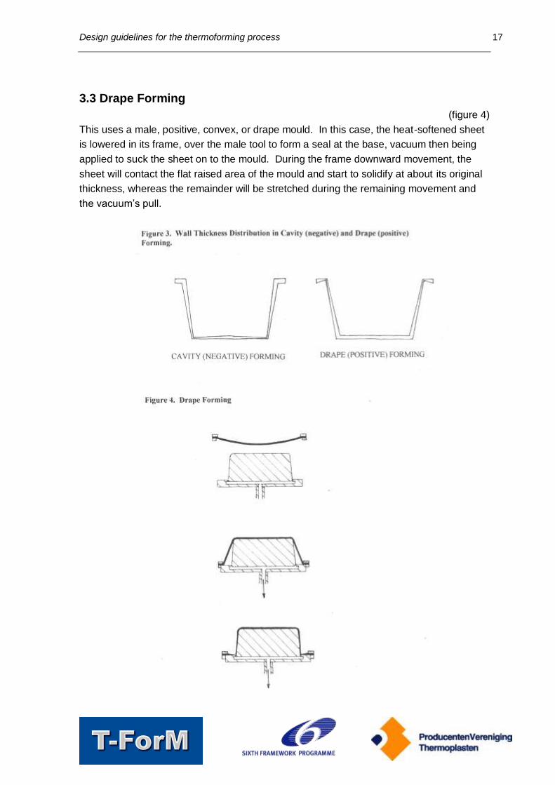
3.3 Drape Forming
(figure 4)
This uses a male, positive, convex, or drape mould. In this case, the heat-softened sheet
is lowered in its frame, over the male tool to form a seal at the base, vacuum then being
applied to suck the sheet on to the mould. During the frame downward movement, the
sheet will contact the flat raised area of the mould and start to solidify at about its original
thickness, whereas the remainder will be stretched during the remaining movement and
the vacuum’s pull.

Design guidelines for the thermoforming process 18
18
As with cavity forming, the last area to form is the thinnest. This avoids thin corners at the
bottom as occurs with Cavity Forming, but is thinner at the rim (figure 3) and prone to
forming webs. Cooling shrinkage can impede part removal.
3.4 Variations to Avoid Excessive Thinning
3.4.1 Cavity Forming with Plug Assistance
(figure 5)
In this process, a central plug pushes the heat softened sheet into the cavity of the female
mould, simulating the drape forming effect on wall thickness, and vacuum is then applied
to suck the sheet against the female tool. Some slippage between hot sheet and plug
may be required to achieve the required wall thickness uniformity, but the plug must be
very smooth to avoid marking the sheet. (Paradoxically, hard felt is sometimes used)(6).

Design guidelines for the thermoforming process 19
19
3.4.2 Billow Drape Forming
(figure 6)
A more uniform wall can also be obtained by inflating the sheet into a bubble as in free
forming and then inverting this half bubble with a male tool. A final vacuum sucks the half
bubble tightly on to the mandrel. A vacuum alternative is compressed air or both vacuum
and compressed air.
3.4.3 Snap-Back Forming
(figure 7)
This is very similar to billow-drape but has the advantage of minimal drill marks, and the
bubble need not be the full height of the male mould.
The sheet is drawn into a half bubble by vacuum, the male mould inserted and the sheet
sucked back on to the male mould.
In a variation described by Gruenwald(5) and illustrated in the BPTA booklet(8), a half
bubble is blown with compressed air, the male mould moves upwards into the half bubble
and the sheet sucked on to the male mould.
3.4.4 Reverse Draw with Plug-Assist Forming
This uses the billow pre-stretching method with plug assistance in place of the male mould
and vacuum forming into a female mould.
3.4.5 Twin Sheet Forming
(figure 8)
Twin sheet forming is a form of blow moulding but using two sheets instead of a hot tube
between 2 mould halves.

Design guidelines for the thermoforming process 20
20
As this is a more recent process compared with the other thermoforming techniques, this
is described in more detail as follows:-
Design guidelines for the thermoforming process 21
21
Twin sheet thermoforming according to Avery(3) had similar advantages over blow
moulding as single sheet forming had over injection moulding, with added economic
advantages of immediate colour and thickness changes. This technique also had product
design flexibility such as different thicknesses between two sides, different materials with
regard to colour, appearance, UV resistance, heat resistance, impact strength etc. and
encapsulation of inserts for stiffening, and fixing.
E Galli(9) summarised the position of twin sheet forming. Twin sheet mouldings were
normally selected because the double wall configuration maximises stiffness e.g. garage
doors, pallets and containers. High molecular weight HDPE was often used as it held
heat longer so enabling shaping of both sheets and welding together plus it had
toughness to withstand knocks, common to many of the applications. Minimum sheet
thickness was about 1.14 mm for HMWHDPE and 1.5 mm for ABS. Thermoformers
normally extruded sheet to required thickness in-house and recycled trimmings and scrap.
Other than blow moulding, the other large rigid product manufacturing processes of
structural foam, compression moulding and SMC, used more costly moulds than twin
sheet forming.
Tooling for blow moulding and twin sheet thermoforming could be cast or fabricated
aluminium with hardened inserts if necessary. Twin sheet tooling was up to 20% cheaper
than equivalent blow moulding, but twin sheet was normally selected for features rather
than cost. Its main advantage over blow moulding was size; up to 2.4 x 3.6 m. Stiffness
was achieved by having many ribs on both surfaces with welded contact points.
Sheets could be formed sequentially to allow inserts, it could use filled sheets, different
colours, different gauges. Plug assist was suitable only for sequential moulding.
Other polymers were used such as PC/PBT for form filled car bumpers, and Ultem
(Polyetherimide) for aircraft ducting. Polycarbonate was used in aircraft at one quarter
cost of welded aluminium.
Twin sheet forming needed correct alignment of 2 tools. Standard dowels and bushes
were used (minimum of two). Pinch-off points and weld lines were designed in to bond
sheets together and form a bead inside along weld lines. This also eliminated trimming
and improved appearance. Venting, blow pin position and size, heating/cooling etc. were
dependant on part design.
3.4.6 Other Techniques
There are many other variations in the text books listed in the references.(5,6,7,8)

Design guidelines for the thermoforming process 22
22

Design guidelines for the thermoforming process 23
23
4. Tooling
4.1 Tooling Costs: Thermoforming versus Injection Moulding
According to Avery(3), trends towards shorter production runs resulting from more frequent
changes in styling and needs to reduce development costs were creating thermoforming
opportunities. Low volumes of 2 to 10,000 units were said to be more economic than
injection moulding even though the starting material was extruded sheet.
The following data is taken from a table for comparative costs of pressure forming versus
injection moulding for 1000 parts per year of an electronic equipment enclosure in Noryl.
Cost of thermoforming aluminium tool with trimming fixtures was $24,150.
Materials and thermoforming cost was $22.29 per unit.
The corresponding figures for a steel injection mould and materials and processing costs
were $134,000 and $13.84 per unit.
Total unit cost including tool amortisation over 2 years was $34.37 for thermoforming and
$80.84 for injection moulding, i.e. a thermoformed part would cost less than 50% of that
made by injection moulding.
Avery’s references were: (13)Gabriele M C Mod. Plast. July 1996, 44 – 47. (14)Schut J H (Ed) Plast. World May 1996, p29.
4.2 Tooling: Design Considerations
Unlike injection moulding, which needs close tolerance machining of matched steel die
parts, stripper plates, ejectors and runners, thermoforming normally needs a single side to
reproduce one side of the moulding. Consequently they are much easier to make (3).
A female mould cavity will be used to produce outside details and a male mould for inside
details. No ejector pins are necessary. Injection mouldings normally require

Design guidelines for the thermoforming process 24
24
minimal if any further work prior to assembly, but thermoformed parts may require fixtures
and jigs for trimming, machining holes, slots etc., although costs of these operations have
been reduced by robot trimmers etc.(3)
4.2.1 Thermoforming Mould Design Criteria
To comply with the dimensional and thermal requirements of the Thermoforming process
the following factors must be considered when selecting a material for mould making:
1. Must be capable of repeated thermal cycling,
2. Must be easily modifiable,
3. Must be able to transmit vacuum from all areas of its surface,
4. Must be robust,
5. Must be dimensionally accurate,
6. Must have a known shrinkage.
The reasons behind these requirements are:
1) Thermal Cycling: to maintain quality, dimensional stability and to avoid brittleness
and moulded-in stresses the temperature of the mould must be controlled within a
narrow range. To achieve this (and to avoid extended cycle times) the mould
material must have excellent thermal performance.
2) Design Changes: the thermoforming process offers fast turn-around and low
volumes – this results in frequent design (and hence mould) changes. One report
claimed that 30% of designs are changed during the mould-making phase.
3) In most applications the vacuum holes must be as small as possible. The
practicalities of drilling very small holes into a mould affects the selection of mould
materials and shell thickness.
4) Robustness can be achieved through the inherent strength of the material or its
thickness (but this has an effect on 3).
5) The plastic will replicate the mould dimensions so design of the mould must
recognise the materials shrinkage and that of the plastic.
Tooling details have been recommended as follows(3):-
Standard practice: Specify either minimum wall thickness or sheet thickness.
Stretch ratio: Ratio of part surface area to original sheet area. Pressure forming
– max 3:1, average 2:1 or less.
Draw ratio: Ratio of maximum mould depth to minimum across open mould
face at given location. For pressure forming <1:1 considered best.
(Note: geometries treated in more detail in section 6.2).

Design guidelines for the thermoforming process 25
25
1) Ribs: (figure 9)
Solid ribs not possible.
For stiffening:
Female mould; outside rib width minimum 1.75 x rib depth.
Pressure forming; minimum distance between ribs = rib height.
Thick walls may require wider ribs.
High pressure forming gives sharp detail; rib width can be 1 – 2 x wall thickness
(see figure 9).

Design guidelines for the thermoforming process 26
26
2) Undercuts:
These are used for locations and snap fits. They normally have large radii and smooth
contours. In pressure forming, moving cores can form 12.5 mm deep undercuts (or
deeper with special tooling). Examples of undercut tooling are shown in the books by
Gruenwald(5) and Illig(7).
3) Tolerances:
Avery’s table(3) gives tolerances for pressure forming only. (Presumably from his
reference; Beall G. Design Guide II for Pressure Formed Plastic Parts, distributed by
Arrem Plastics Inc. (Addison IL).
General: ± 0.030 (presumably in inches i.e. 0.76 mm)
Drilled holes CL to CL: ± 0.020 (0.5 mm)
Computer machining: ± 0.020 (0.5 mm)
4) Draft (taper):
A taper is needed for part removal.
Male moulds: 3° minimum
Female moulds: 1° for smooth tool surface
1° of draft for every 0.025 mm of texture depth
5) Basic Considerations:
Which side of the part contains the detail?
At what locations are tolerances required?
Are different parts assembled and must they fit together
Male moulds are less expensive than female moulds
Are “matched” moulds required
6) Trimming:
For economy, edge trim should all be in the same plane. To achieve tolerances, trimming
should be carried out after all post moulding shrinkage has occurred. An example is given
of an ABS part 1.2 m wide changing 1.8 mm due to a 5°C difference in temperature. CNC
milling, high-pressure water jets and lasers can be used.
4.3 Heat Transfer Considerations
For thin gauge sheet Throne (7) states that the mould surface temperature should be
above the temperature at which in-mould condensation can occur. Condensation causes
dimples in the walls of formed parts.

Design guidelines for the thermoforming process 27
27
For heavy gauge sheet Throne (7) states that the mould surface should be ca. 5ºC below
the Glass Transition Temperature (Tg), the Heat Distortion Temperature or the
recrystallization temperature of the polymer.
For low volume or prototype applications where cycle times are of less importance the
mould can be constructed from materials such as Resin, Plaster or Wood. The thermal
properties of these materials do not permit accurate control of mould surface temperature
and frequently the mould temperatures are significantly lower than the ideals stated
above. Although low mould surface temperatures decrease cycle times, excessive
residual stresses are locked into the formed parts under these conditions.
Some of the stresses may be relieved during trimming, when the product is stored at
elevated temperatures, during shipment, or in use. These stresses can result in a
deformed or distorted part. Mould surface temperatures should be high if replication of the
mould surface of the sheet is required – e.g. in pressure forming off a textured mould.
4.3.1 Mould Temperature Control
Channels within the mould or bolster plates are normally used to add and remove heat
from the mould. Water is the most common cooling medium because it is efficient in
adding or removing heat. For higher temperature moulding where the mould temperature
has to be maintained above 80-90oC it is safer to use Hot Oil. And it is not uncommon to
add cartridge heaters to moulds for parts with difficult designs.
To achieve uniform heat transfer across the mould surface it is imperative that the fluid
has turbulent flow everywhere in the coolant channel, regardless of the fluid used. To
achieve turbulence water should be flowing at least 0.34m/s in 25mm internal diameter
lines and 0.7m/s in 13mm internal diameter lines. Typically, Thermal Oil has higher
viscosity and lower density than water and, as a result, must flow faster to remain
turbulent.
Temperature across the mould surface should vary by no more than 1ºC and the fluid
temperature rise should be no more than 3ºC. Part-to-part non uniformity in thin gauge
multicavity moulding and warping and side-distortion in heavy-gauge moulding are
frequently directly attributable to non-uniform mould surface temperature.
4.4 Tooling Materials
In a review of rapid prototyping in general but which tends not surprisingly to be biased
towards injection moulding, the author(10) quoted a consultant who divided the techniques

Design guidelines for the thermoforming process 28
28
into “additive” and “subtractive”. Additive tooling used techniques such as
stereolithography while subtractive used material removed by CNC techniques.
The many additive techniques were more easily applied to thermoforming as only one
mould piece was needed, and it did not need to exactly mate with a second piece to form
a cavity and stresses involved were comparatively low. As the wall thickness of vacuum
formings were (by the nature of the process) variable, the lesser precision of additive
tooling compared with subtractive would normally not be a problem. For subtractive
prototyping, aluminium or aluminium filled epoxy was normally used.
In a table comparing 5 different tooling techniques, the additive methods lead times
tended to be 1 to 2 weeks and CNC machined aluminium 4 weeks. The overall situation
at this date (May/June 1998) was that all the systems compared benefited from CAD to
produce relatively accurate tooling of reasonable durability in a comparatively short time.
Not mentioned was what remedial actions, (if any), were possible if design changes
proved necessary.
For many years prior to CAD/CAM and stereolithography techniques, moulds were either
hand made or replicated using casting and hand laminating techniques from hand
fabricated/semi machined materials. These techniques may still be the only practical way
of producing prototypes and short runs in some circumstances, particularly for large
components.
R Harris(11) produced a book in 1973 which includes details of producing thermoforming
tools from wood, plaster, epoxy and polyester resins, fablite, and sprayed metal without
CAM and rapid prototyping. The starting point was the skilled pattern maker.
The criteria to be met were:-
1) The labour and materials cost should be low.
2) Modifications to the mould should be possible for design changes.
3) The mould must not deflect or deform during moulding.
4) The mould must withstand 65 to 93°C.
5) Part appearance must be acceptable.
It was emphasised that ease of alterations could save time and money should revisions
be necessary.
Avery(3) divided tooling materials into 3 categories:

Design guidelines for the thermoforming process 29
29
Material Applications
1) Hardwood Prototypes and pilot runs
2) Filled epoxy Low volume production
3) Aluminium (cast or machined) Full production
Steel was not mentioned. It should be noted that Avery excluded high speed thin sheet
packaging from his book presumably as this was outside his remit. He stated that
aluminium was used not only for its durability, but good thermal conductivity combined
with heating/cooling channels minimised moulding cycles. Illig(6) stated that aluminium
was the preferred material for thermoforming tools. The advantages of aluminium were its
good heat conductivity and ease of machining.
The advantages of aluminium are its good heat conductivity and ease of machining.
Thermal conductivity data for various potential tooling materials are given below.
Tooling Material Thermal conductivity
(10-3 kw/m ºC)
Aluminium 124
Resin 1.3
Plaster 0.298
Wood 0.125
Table 1: Tooling Conductivity Data
As can be seen aluminium conducts heat 1,000 times better than wood and 100 times
better than a typical resin. Metals are conductors, whereas polymer based materials are
thermal insulators.
Therefore, aluminium because of its cheapness, availability and the highest thermal
conductivity of all common mould materials is the preferred material for production
moulds.
Aluminium moulds can be cast or machined, or a combination of both. Temperature
control piping can be cast into the mould, fixed to the inner wall of the mould or bored in
machined moulds. The strength of the metal allows moulds to be made with a 25mm wall
thickness to give the robustness, short vacuum holes and a vacuum chamber.
Prototype moulds and moulds for low volume applications are usually fabricated from
more easily worked materials such as resins or composite materials.

Design guidelines for the thermoforming process 30
30
If the utilisation of filled resins and composites is small, then there is a surprising number
of different brands described in editorial review type journal articles. This might be
explained by Illig’s statement, that “due to the various areas of application and the
different versions of thermoforming machines available, specialist tool making branches
have evolved over the years”.
4.1.1 Wood
According to Harris(11) kiln-dried hardwoods such as birch, maple and mahogany are the
most common varieties used. Mahogany was considered easier to machine and glue, but
all woods changed dimensions with humidity if not sealed with suitable varnish. Insulating
properties would result in heat build up and forming halted by lack of cooling. Conversely,
plug assist benefited from heat build up. Details of jointing, producing inside radii,
countersinking screws, end grain problems etc. were dealt with.
Throne(7) covered similar points but also rated 7 species on a 0 to 100 scale for planning,
shaping, drilling, sanding and resistance to splitting. Whilst maple, birch and mahogany
were commonly used according to Harris, Throne’s table shows maple poor for sanding
30-39 and mahogany with 40-49 rating for shaping and resistance to splitting, with no
mention of birch. Ash rates well except for shaping at 50-59.
Vent holes were usually drilled through the primary surface first and counter bored with
larger holes from the back. Epoxy enamels and varnishes were said to give sufficient
protection for hundreds of cycles, but softer bands within the wood grain could result in
unacceptable texture from preferential shrinkage. Throne also tabulated mechanical
properties of a number of woods (excluding mahogany).
4.4.2 Plaster
According to Harris(11), in most cases, plasters needed replication from a model or pattern.
Unlike other mould making materials, plaster expanded, a property which might be used
to offset moulding shrinkage. Being fragile, plaster needed careful mounting, whilst fibres
or wire mesh reinforcement could be used. Procedures for casting male and female
moulds were described. Vacuum holes could be formed by placing fine piano wires in
position and withdrawing with pliers after cure.
Throne(7) considered most commercial moulding plasters were not strong or tough enough
but a table was given of setting times and compression strengths for five moulding
plasters. “Splatting” a thin layer of high water content plaster on the mould pattern surface
produced a very hard void free finish to the plaster mould. An optimum water content was
needed in the mix to achieve good physical strength whilst avoiding air bubbles and voids.
The process is exothermic and drying for several days may be required. Although durable

Design guidelines for the thermoforming process 31
31
and able to withstand cyclic forming temperatures, when they do break they are not worth
repairing and a new mould will be cast from the pattern.
4.4.3 Sprayed Metal Alloys
Excellent surface detail could be replicated by spraying low melting point alloys against a
pattern(12). These tools were suitable for full production as well as prototypes. It was
sprayed much like paint. As there is no heat build up in the pattern, many materials
including plastics can be used for the pattern. Once a surface of 1.6mm to 3.2mm has
been deposited, the back can be filled with epoxy/aluminium and other materials
described below. As with plaster and cast epoxy resin based materials, piano wire can be
used to form vent holes. When the tool is no longer required, the metal can be re-used.
4.4.4 Resin Tooling
Thermosetting liquid resins for thermoform tooling get regular mention, mainly in
superficial review articles, which make their relative technical merits difficult to assess.
Although there are far more references to resin composite tooling than aluminium tools, to
quote Illig(6); “aluminium-resin combinations are rarely used”.
In general, tools using resins appear to fall into two categories although not formally
described as such:
1 Large moulds in which techniques resembling GRP boat building are used with hand
lay-up or spraying using fibre reinforcements, plywood stiffening etc.
2 Smaller moulds where filled resins are either cast or machined.
For large moulds, polyester resins are frequently used, as material costs are lower and
glass fibre reinforcement is readily incorporated. The fabrication of polyester-glass fibre
tools, which is described in detail by Throne(7) and Harris(11) although similar to boat
building may require considerable stiffening to withstand the comparatively high loads
imposed by 1 atmosphere over a large area. Epoxy resins, which have superior heat
resistance to polyester resins, can be used, although more expensive and harder to
fabricate.
An article by Reimann(12) covers use of synthetic resins for a wide range of tooling
applications including sheet metal forming and foundry work, but includes plastics
processing.
1) Polyurethanes: These varied from rigid to flexible; fast curing reactions were
possible and they had resistance to wear and abrasion.
2) Methacrylates: They had high flowability, fast curing reactions and thermal
resistance.

Design guidelines for the thermoforming process 32
32
3) Silicone polymers: They had self-releasing properties, high elongation, easy
demoulding and high thermal stability.
4) PMMA casting resins: When filled with high levels of aluminium powder they
offered fast processing, fast curing, and good machinability. Large moulds had
shown good performance in many years production. Heat shrinkage during curing
could be a problem.
5) Epoxy Resins: These were used for dimensional stability, mechanical strength,
thermal stability and adhesion to fabrics and fillers. Previously Epoxy Resin tools
were restricted in temperature performance (max 125OC) but new resins claim to
be able to withstand much higher temperatures.
Modern Aluminium-filled casting resins can be supplied in liquid form and are typically
ready for finishing within 48 hours. Although the product literature claims “good thermal
conductivity” there is no data to make a reliable comparison with Aluminium. Cooling
channels can be cast into the Resin but must be located close to the surface. Problems
may arise if the design of the product has to be changed. Removal of resin can be easy
but addition of resin may be difficult. Care must be taken to ensure that identical resins
are used to avoid differential expansion. Adhesion of the additional areas may be difficult.
By using an equal weight of several layers of glass cloth with a specially formulated heat
resistant resin, moulds of high accuracy, heat resistance and thermal stability can be
achieved. A 30 – 50 mm back-up uses a mixture of resin and aluminium granules.
Nowak(13) divided thermoforming mould materials for models and prototypes into “direct
methods” and “indirect methods”. An example of the direct method was to make a male
model in polyurethane foam, seal with a filler and then spray a zinc/tin alloy to a 0.5 – 1.0
mm thickness by flame spraying. The surface was then rough sanded. The tool shape
could be modified by sanding and/or adding filler.
In the indirect method, an impression of an initial model was used to form a male or
female mould. Brittleness of gypsum and embedding compounds under thermal loads
limited their use to intermediate models. The surface layer applied to a model could be a
polyester or epoxy resin containing slate or aluminium filler to give a 50 mm thickness. 2
mm slate platelets gave a porous layer, making drilled holes unnecessary, unlike moulds
of wood, aluminium, zinc, brass or steel. This was in 1980.

Design guidelines for the thermoforming process 33
33
4.4.5 Aluminium
Illig(6), Gruenwald(5) and Avery(3) considered aluminium to be the primary material for
production tools. It can be used (cast or machined) not only for its durability but good
thermal conductivity combined with heating/cooling channels that minimises moulding
cycles. Steel inserts can be used for clamping and other areas requiring increased
hardness. Aluminium is also suitable for higher pressures in sheet pressure forming and
twin sheet forming. As more design work uses CAD, machining has become more
popular as CAD can be directly transferred to CNC machining equipment. This also
allows it to be used economically for small test tools. Sand or ceramic precision casting
should only be used for aluminium tools in those cases, where machining proves
uneconomical, but even so, a machined pattern could be the starting point. Aluminium is
an easy machining material and higher specifications for strength are available from
certain alloys. Shot peening of cast aluminium tools eliminates surface porosity. It is also
suitable for the higher stresses in sheet pressure forming and twin sheet forming.
4.4.6 Steel
Nothing was found on the use of steel for thermoforming moulds. Davis(14) gave a very
comprehensive review of steel and alloys for mould tools, but this was essentially for
compression and injection moulding.
4.4.7 Russian Tooling Practice
An article by Sheryshaev(15) covered similar ground to Harris(11) and Throne(7) but is
included as a separate item as although the translation is difficult in places to understand,
it contains a number of points which were not found elsewhere.
There is some extra detail on plaster moulds which covers influence of drying times and
temperatures on durability. Curing was also said to be improved by impregnation with
30% iron or copper vitriol solution and also with a weak liquid glass solution. As non-
impregnated plaster moulds are porous, evacuation holes need to be provided only where
the most intense suction is needed.
Cooling of cast polymer moulds can be by a “cooling jacket” which also reinforces. In
more complex geometry moulds, cooling is by a small metal tubing coil 6 – 10 mm from
the mould edge, wired in position during casting.
A process of “stone casting”, which is similar to cast resin and ready after 30 hours
requires no additional treatment. Vacuum holes are provided by wires removed after 14
hours of the 30 hours hardening time but metal reinforcements need protection against
corrosion. Glass fibres can be used. Coils within the mass can also be used to remove
heat released during curing.

Design guidelines for the thermoforming process 34
34
In addition to metal moulds, electroplated concrete moulds can be used for prolonged
service. They were described as consisting of a thin-walled moulding marker/shell, which
is placed in a metal casing and flooded with a non-metallic support e.g. concrete. A full
description was given of what appears to be an electro-deposited metal replicate backed
with concrete. An odd assortment of materials including lacquered paper-maché were
also mentioned.

Design guidelines for the thermoforming process 35
35

Design guidelines for the thermoforming process 36
36

Design guidelines for the thermoforming process 37
37
5. Proprietary resins and resin based materials for tooling
These are mostly epoxy based as having the best heat resistance. The earliest
proprietary material described specifically for thermoforming covered by the computer
limited search period was the 1973 article by Harris(11) , but epoxy based jig and tooling
materials were used for engineering purposes long before then.
5.1 Axson EPO 4042 EPO4042/L Epoxy Casting Resin
This is an aluminum-filled two-part epoxy casting resin for vacuum-form tools. Midas
patterns report that it is a good casting system, offering good temperature resistance and
edge strength. The system needs a master pattern in order to cast the vacuum. The
material is stable and long lasting, ideal for low - medium volume runs (100 - 2000 off). A
data sheet is provided in the appendix.
5.2 Epon Epoxy Resins
According to Harris(11), castable resins were widely used for thermoforming tooling and a
two impression aluminium-filled epoxy mould and thermoforming are illustrated. The
resins (usually epoxy) were well filled with aluminium to improve thermal conductivity and
hence cycle time. A model or pattern was normally required.
Details of making a mould using resins were given. As materials were not inexpensive
and large moulds could be heavy, they were frequently filled with a porous backing which
also simplified the provision of vacuum holes.
The surface coat was aluminium filled resin applied to a thickness of 2.54 to 3.175 mm.
The rest of the pattern was filled with epoxy coated aluminium needles, not packed tightly
but tamped lightly so that the voids between needles were interconnected, making the
filler porous. The vacuum holes were drilled through the surface coat in the required
places.
The aluminium-filled epoxies were readily available from many well-known suppliers. A
premixed aluminium needle-epoxy package was available but required a 177°C cure
temperature. Alternatively a room temperature curing mix could be prepared as follows:-
Epon 815 epoxy resin 200 g
Shell T-1 curing agent 50 g

Design guidelines for the thermoforming process 38
38
Aluminium needles 2000 g
The needles were coated just sufficiently to stick together.
5.3 Fablite
According to Harris(11), Fablite Incorporated of Romeo Michigan, granted licences to make
moulds by its patented process (which will have expired by now) to produce porous tools
which had no need for vent holes. A filler such as aluminium powder was mixed with the
Fablite binder (material undisclosed) and used to make a mould in a similar manner to the
epoxy system. The cure cycle involved 5 steps which volatilised excess resin leaving a
permeable to air surface coating.
As with the epoxy moulds, the Fablite mix could be confined to the surface, which sped up
the forming cycle, and the rest of the mould filled with an aluminium grain and resin
combination.
5.4 Polylite Polyester Resin
In work reported by Brooks and Walsh(16) to predict mould surface temperature using an
FEA model, the mould used was made from a filled Polylite 33540 – 00 zero shrink mass
cast tooling resin. The material composition was 50% aluminium powder and 35%
aluminium pellets in zero shrink polyester resin. The aluminium increased thermal
conductivity from 0.17 to 3.36 w/mk. Heat capacity was 1050 J/Kg K and density 2110
kg/m3.
5.5 Metapor Epoxy/Aluminium
Knights(17) reviewed thermoform tooling using porous material from Portec produced since
1995. It consisted of 65 – 90% aluminium powder, 10 – 35% epoxy resin and had 15%
voids. Its surface had pores of 15 – 16 microns diameter. It was used for prototypes,
production moulds and cavity inserts. It was supplied in machinable blocks or castable
material called Espor (see 4.5) and used with most plastics for thin gauge packaging,
fridge door liners and automobile dashboards.
It was said to reduce lead times as elimination of drilled surface holes reduced CAD and
machining times. The porosity gave faster cycles from faster draw, and cooling starting
sooner. Plug assist sometimes became unnecessary. With some tools the drawn air

Design guidelines for the thermoforming process 39
39
provided all the necessary cooling which made it particularly attractive for prototype
tooling.
Being polishable to 200 grit, although not to the potential surface finish of aluminium, it
could give high detail or optical quality without marring surface. (In any case highly
polished tools could make demoulding difficult). It was suitable for large flat products free
from vent marks and surface imperfections, and there would be no
“lakes” or “wave effects” from air trapping. Transparent polyolefines could be high gloss
sheet with no scuffing due to sliding. It also gave fine surface detail such as leather
grains, lettering etc. and also saved time by eliminating drilling holes for fine details.
The porous material enabled unusual shapes to be made where otherwise vent locations
would be extremely difficult to drill.
Disadvantages were that plates greater than 100 mm thick reduced air flow rate due to
increased pressure drop and cooling temperature gradient became too large. For deep
moulds, hollow box sections of thin slabs joined with epoxy resin were recommended.
Vacuum ports required attention to get uniform draw, and vacuum channels were
arranged in a grid pattern on the back of the mould. Portec suggested a 300 x 406 x 38
mm mould should use vacuum distribution channels 15 mm wide x 5 mm deep, 50 mm
apart. Main vacuum pipe should be mounted centrally to prevent out of balance draw.
CNC machining was recommended but the epoxy limited use of EPM and polishing could
reduce porosity by partial pore blocking.
The pores were so small that blockage was not a problem and any contaminant could be
blown back. Repairs were possible.
The material was softer than standard aluminium but had been used for 1.6 to 5 million
parts. It was used for decorative inserts for cell phones etc. where vent marks must be
avoided.
Material costs were twice that of 6061 aluminium. It was produced in 500 x 500 mm slabs
10 to 400 mm thick. A standard 500 x 500 mm slab would be needed for a 150 x 100 x 50
mm mould and would cost $750 (in 2001). Price could be reduced by confining use to
inserts.
Savings on machining depended on tooling e.g. multiple cavities requiring many vents
with solid tooling would be economic. Normal temperature limitation was 108°C but high

Design guidelines for the thermoforming process 40
40
temperature epoxy allowed 210°C. Metapor HD210 had improved heat resistance for
forming polypropylene and acrylics. “Protoblack” was produced for cost effective
prototype tooling.
5.6 Espor
For textured deep-draw detailed moulds e.g. for automotive applications a castable
version of Metapor called “Espor” could be used. R L Bowen(18) described some of its
uses. A pattern made of wood, epoxy, or any rigid material could be replicated. Espor
was mixed and poured with in-situ cooling pipes as required and strengthening ribs as
needed if a typical aluminium shell type tool was made. When set, excess material was
milled off, the tool “squared up” and cured.
A long list of advantages was included as follows:-
No size limit.
Good texture detail.
36% lighter than aluminium.
Rapid tooling.
Shrinkage only 0.01%.
Wear resistance as good as aluminium.
Undercuts possible (with slides).
Can be cleaned with soap and water and reverse blow dried.
No costs or disadvantages were included.
5.7 Vestalloy
Included in a review by Tolinski(19). Made by Matrix Composites LC USA.
A metal filled vinyl ester compound said to retain its properties at most thermoplastics
processing temperatures. It contained “uniquely configured” filler particles to provide good
thermal properties. It was said to perform well in thermoforming as well as RIM,
compression and foam in place moulding. Injection moulding was being investigated as it
had excellent cohesive strength and withstood temperatures up to 260°C. Compared with
standard epoxies, it had about 20% higher wear resistance, at least double thermal
conductivity and better machinability than standard materials. The article’s table rates
wear resistance and dimensional accuracy to be similar to aluminium.

Design guidelines for the thermoforming process 41
41
5.8 WIS Tooling
This technology by Cubital America Incorporated (also in Tolinski’s review(19)) produced
aluminium filled epoxy tools from a prototype part made by UV curing successive layers of
a special photopolymer. A temporary wax support was used during replication; termed
the “wax-in shell” (or WIS) method. Tolinski’s table rated wear resistance less than
Vestalloy and gave tool life as <1000 parts.
5.9 Albright RT
Albright Technologies Incorporated RT(19) was not a composite in the filled resin sense,
but a two component tool used for injection moulding in which a cast room
temperature vulcanising silicone rubber was supported within rough machined cavities in
an aluminium support. The silicone insert was cast from a stereolithography pattern and
when excessively worn, e.g. after 1500 mouldings, the insert could be replaced with a new
silicone insert.
5.10 Poly Steel
Devised by Dynamic Tooling (USA), Poly Steel is a 90% steel filled epoxy said to be
400% stronger than aluminium filled epoxy(19). Using stereolithography patterns, accuracy
was better than 2 rms surface finish and 0.001 mm/mm of the SL model as expected by
motor industry customers. It was said to be suitable for injection moulding 30% glass
filled nylons at 300°C without degrading or wearing. Tolinski’s table(19) rated heat transfer
similar to aluminium epoxy but wear resistance and dimensional accuracy rated better and
tool life given as 100,000 + parts.
5.11 Microsyn
There is brief mention in a summary of an SPE Thermoforming conference presentation (20) on Microsyn two part epoxy based Syntactic foam. (Matrix Asia Pacific).
1) Ambient cure system
2) Resistant to 120°C
3) Designed for large castings
4) Can be used in conjunction with “microballoons”
5) Low thermal conductivity prevents overheating of moulds

Design guidelines for the thermoforming process 42
42
(note: not obvious why this should be)
Used for 3 mm ABS sheet with a sheet temperature of 200°C.
5.12 Ren-Shape (Vantico)
Ren-Shape 5008 board from Vantico(21) can be used for making prototypes and short run
mould bases or cavities. Ren-Weld 5008 adhesive is used for bonding boards, together
with Ren-Patch repair paste.
Mills Manufacturing in Oregon used Ren-Shape epoxy laminating system Ren RP
4005/RP 1510H for tools to thermoform 6.5 mm polycarbonate mouldings to protect luxury
motor homes from rocks and other road debris. Tools were moulded vertically against the
actual vehicles.(22)
Knights(23) (editor) gave some details on Vantage Tool and Engineering’s manufacture of
low cost thermoforming moulds using Ren-Shape type 450 board. This was a filled
polyurethane having a glass transition temperature of 96 0C, Shore hardness 65D and
tensile strength 160Kg/cm2. The boards were 100mm thick, size 0.406x1.25m several
boards were laminated together as required with Ren-Weld 103 adhesive, enabling
cavities with up to 600mm depth of draw to be made.
Typical mould manufacturing time was 3 days compared with 2 weeks for aluminium. A
small Ren-Shape mould of 300 x 300mm could be made in a day.
Machining practice developed by VTE was to use two fluted hardened steel ball-end mills
at 3500 rpm and 3.27m/min rough cutting, beginning with an 12.5mm deep cut, followed
by 25mm cuts and then 40mm deep cuts. Finishing cuts were made with 6.5mm tapered,
fluted end mills at 4500-5000 rpm and 0.38-4.0m/min, using 0.178mm stepover to
produce mould surfaces requiring no secondary finishing. (Note: e-mail from Huntsman
(Europe) suggested BM5055 board data-sheet, (see in appendix), would have similar
machining properties).
The finished cavity was inserted into a standard aluminium mould base. As heat built up
may damage the tool, with thin sheet thermoforming the tool must be allowed to cool after
a few mouldings. However with heavy gauge sheet, the tools heat retention gives good
part definition and the slow cycles allow up to 500 heavy gauge parts to be made,
whereas with thin gauge the limit may be 50 cycles.

Design guidelines for the thermoforming process 43
43
Ren-Shape moulds up to 1.5 x 1.8m were used to form a truck cab’s dashboard, interior,
roof, fridge, stove and bunk.
5.13 Polyurethane Machinable Slab (Ureol Board Axson)
Materials are available in different densities.
Lab 1001 from Axson is described as a Tooling Board; with applications in checking
fixtures. It is available in 50mm and 100mm thicknesses and can be adhesive bonded. It
has an SG of 1.60 g/cm3.
Prolab 65 from Axson is designed for the production of patterns, mock-ups, prototypes
and masters by milling or machining by hand. Slabs are available in various sheet sizes in
30mm, 50mm, 75mm and 100mm thicknesses. They can be bonded together adhesive or
mastic. Slab density is typically 0.6g/cm3 with a Shore D1 of 63.
These materials were identified by Midas patterns and data sheets are included in the
appendix.
5.14 Epoxy / Aluminium using Stereolithography (Escuelo Technica)
A well illustrated and detailed article by P Lafont Margodo and G Garcia Martinez de
Saleras (in Spanish) described the manufacture of a tool in 70% aluminium powder and
30% epoxy resin EP250 using stereolithography. Heat distortion temperature was 250C. (24)
5.15 Miscellaneous Materials
A number of materials are briefly described in press releases and summaries with little if
any technical information. From the technical press articles, these products are often used
with stereolithography but it is not always clear whether for a prototype, a master for
replication, or the tool itself. In many cases the intended moulding technique is vague
with thermoforming as an afterthought.
Articles appearing over the last 10 years which appear from their abstract to have
reasonable evidence of their suitability for thermoforming tooling are summarised as
follows:-

Design guidelines for the thermoforming process 44
44
1) Axson (France) epoxy/PU. The fast setting epoxy/PU.F50 can be used to produce
models, prototypes or production tools requiring very thick castings. (25)
2) 3D Systems and Ciba Speciality Chemicals supply Cibatool SL 5530 HT epoxy which
was used with stereolithography to produce vacuum formed 0.6 x 1.5m polycarbonate
shield for Bell Augusta tail rotor. The tool withstands 200°C. (26)
3) (In Spanish). A selective laser sintering (SLS) 2000 service is offered by AIJU for
plastics prototypes and moulds (27).
4) (In Spanish). The types of moulds which can be produced by MCP metal spraying are
discussed (28).
5) T2L Chimie of France is a Ciba Speciality Chemicals subsidiary supplying thermoset
casting resins(29).
6) Cibatool PU tooling board BM 5185(30) can be used as a replacement for hardwoods.
Ureol J146A/B is a two-component Polyurethane mass casting system. Araldite epoxy
tooling paste applied in layers by a dispenser gives a seamless wood-like finish.

Design guidelines for the thermoforming process 45
45

Design guidelines for the thermoforming process 46
46

Design guidelines for the thermoforming process 47
47
6. Tooling: plug assistance
6.1 Plug Assisted Thermoforming
Ayhan and Zhang(2) in their introduction considered the non-uniform wall thickness and the
thinning at container bases were the most significant thermoforming limitation. This was
caused by the heat softened sheet not contacting the mould surface at the same time but
in sequence. As the wall formed last is the thinnest, a female mould will produce
containers with thick rims and thin bottoms, and a male mould will produce the opposite.
(figure 3) Among the various techniques employed to produce more uniform wall
thicknesses was a female mould combined with plug assistance pre-stretching. (see
section 2.4.1 and figure 5). This enabled the moulding wall thickness to be increased in
load bearing regions. However, thickness distribution was never uniform. Aroujalian et
al(31) were cited as showing that wall location, plug temperature, plug velocity and their
interactions influence wall thickness.
Illig(6) considered plug assistance was necessary to prevent excessive thinning at the
bottom of female formings when depth was greater than 3 times opening width/diameter.
The operating sequence is as follows (figure 5).
1. The sheet is heated to the forming temperature.
2. The female forming tool moves up and the plug simultaneously moves down,
stretching the sheet mainly at the sides.
3. When mould and plug movements are completed, vacuum is applied, (and/or
optional positive air pressure from above).
4. Plug retracts.
5. When cooling completed, forming is ejected. (It appears to be used mainly in the
thermoforming of thin wall packaging). Thickness at the thermoformings base can
be increased by enlarging the plug to minimise the space between it and the
mould and by advancing the plug movement relative to the mould.
The plug requirements are as follows:
1. Chilling of hot sheet must be avoided otherwise sheet will not be drawn uniformly
against the tool.
2. Surface must allow hot plastic sheet to slide.
3. It must be mechanically sufficiently robust.

Design guidelines for the thermoforming process 48
48
4. It must have adequate heat resistance.
5. It must be easy to machine and produce at economic cost.
In a table covering an extremely wide range of thermoformable materials, four or more of
the seven listed materials could be used. These were laminated wood, nylon 6,
polyurethane-talc, felt, hollow glass spheres/epoxy syntactic foam, “Pertinax” and Acetal.
Aroujalian et al(31), carried out experiments of a practical nature to determine the influence
of plug velocity and sheet temperature on wall thickness variations and average wall
thickness in vacuum formed strawberry containers using HIPS sheet 0.34 mm thick.
Sheet/film temperatures of 118, 125, 136, 150 and 165°C, and plug velocities of 0.15,
0.20, and 0.27 m/s were used with plug temperatures of 25, 60, 100, 123 and 125°C. The
female aluminium mould was at 25°C. The square mould with radiused corners was 100
x 100 mm at the top, 80 x 80 mm at the base and 70 mm high. A drawing of the plug was
shown, top 82 x 82 mm, bottom 69 x 69 mm and height 67 mm. The metallic plug
(material not specified, but probably aluminium) was heated, and temperature controlled
using 4 electric pencil elements.
Data for 0.15 m/s plug velocity and plug temperatures of 25 and 60°C were not included
as forming was incomplete following sheet chilling by the plug. Graphs of wall thickness
at 10 mm height increments from bottom to top showed a steady fall from lip to base with
no plug, and a reasonably consistent value from 10 mm below tip (approximate thickness
of sheet) to base for plug assistance. (Report figure 10 reproduces Aroujalian et al. figures
1 and 2 from reference (3)).
The highest mean wall thicknesses were obtained at optimum plug temperature range of
100 – 123°C, and plug velocities of 0.15 and 0.27 m/s. Minimum wall thickness variations
were obtained at the highest plug speed (0.27 m/s) and lowest plug temperatures (25 and
60°C). Reference was made to Shih(32) who made similar observations for APET. More
uniform wall distribution was achieved from elastic high speed deformation obtained with
reduced stretching time and reduced heat loss from sheet to plug.
In a paper on the influence of film temperature on wall thickness the reviewing
background preamble by Poller and Michaeli(33) mentions that the parameters of
orientation and crystallisation can be readily changed only by controlling heating and
cooling as moulding geometry is specified. However, if changes to the tooling appear
necessary, the plug will be attended to first as this entails lower costs than attention to the
mould.

Design guidelines for the thermoforming process 49
49
6.2 Plug Materials
As described in section 5.1 the thinning at the corners of parts formed in female moulds
can be reduced by using an appropriately designed plug to pre-stretch the sheet. The
plug, which is attached to a movable platen, pre-stretches the hot sheet to an outline
similar to, but obviously less than, the internal profile of the female mould (see figure 5).

Design guidelines for the thermoforming process 50
50

Design guidelines for the thermoforming process 51
51
As further forming takes place after the plug stretching, the plug must not excessively cool
the sheet and should not mark the sheet surface. In order to provide sufficient corner
thickness whilst maintaining side walls that are thick enough and base not excessively
thick at detriment of corner thickness, some slippage may or may not be required. This
means that coefficient of friction between hot sheet and plug may be an important factor.
Plug materials can be the same as mould materials or can be a generally available
insulating material or a specially formulated material.
Plug materials generally fall into three categories(5).
1) Aluminium. This needs a smooth surface and heating to 5°C less than sheet
temperature to prevent chilling and yet avoid sticking.
2) Wood, composite or metal with insulating surfaces. The surface on any material
can be fabric or felt, or non-stick plastic.
3) Skeleton plugs made of welded rod, with smooth corners and insulating coating.
In the design of “pre-stretchers”, Illig(6) advised keeping a constant spacing between plug
and tool all round.
For roll fed (thin sheet) machines, Illig(6) recommended different plug assist materials for
different plastics, as shown in the following table:
POM (Acetyl) Felt (hardened) Syntactic Foam
HIPS - -
Styrolux -
PP -
PP clear - -
PVC -
PVC clear - -
PETG, APET -
PET crystal clear - -
1) For PP, felt gives thick cup bottom as too rough.
2) For HIPS, PTFE gives thin bottom.
3) Use PTFE when PE is multilayer outer surface.

Design guidelines for the thermoforming process 52
52
6.2.1 Acetal (e.g. Delrin)
1) Cost effective.
2) Problem free fabrication.
3) Best for crystal clear formings.
4) Unsuitable for PVC.
5) Long term exposure to heat limited to 110 – 120°C: surface becomes smoother,
discolours and cracks.
6) Surface usually needs roughening every 30 – 100 hours of operation. Exception is
polished plugs for crystal clear mouldings.
7) Chilling by cold plug at start-up is no problem with PS.
6.2.2 Hardened Felt
Comments applied to felt hardened with Formulation 647 supplied by Filzfabrik Fulda in
sheets up to 80 mm thick.(6)
Alternatively, Clou low viscosity primer can be used to surface harden.
1) Easy start up with PS and PVC.
2) Not used with transparent plastics due to severe marking.
3) Sticks to PP.
4) Easy to install.
5) Relatively expensive.
6.2.3 Syntactic foam
(see item 6 below)
1) Suitable for most materials except for crystal clear mouldings.
2) Dusty machining.
3) Can be cast.
6.2.4 Wood
Solid maple recommended for best sliding properties, but soft textile surface improved
sliding and reduced chilling. Plywood is unsuitable as it may leave marks.
6.2.5 Resins
Used for complex shapes. Polyurethane said to be excellent. Plugs can be 100% resin,
wood/resin combination or talc filled resin to improve sliding.
6.2.6 “Hytac” Syntactic foams
Matrix Asia Pacific(20) listed 6 materials (including competitors) which had been tested on
an in-line thermoforming machine using PP sheet, but few details are given from the
conference presentation. Also associated with CMT(34) .

Design guidelines for the thermoforming process 53
53
1) “Hytac W” (180°C) and “Hytac R2 (235°C)
Described as a high temperature epoxy based syntactic foam.
Thermal conductivity as low as 0.08 w/m°K.
Densities of approximately 0.6 g/cc.
Improved surface finish (semi-polished from high glass content.
2) “Hytac WF”
Described as a fine surface finish epoxy based syntactic foam. “Ultra fine grade” (contains PTFE)
Improved clarity for APET and other clear polymers.
Reduces sticking of HDPE and similar polymers.
3) “Hytac B1-X”
Described as a thermoplastic syntactic foam.
Temperature resistant engineering thermoplastic (unspecified) syntactic foam.
Improved impact and durability.
Lower thermal conductivity than Delrin (Acetal).
Easy to machine.
30% higher temperature resistance than Formplast.
These materials were used by Hegemann and Eyerer (IKP Stuttgart) and co-authors
Tessier of CMT Materials Inc. and Bush, Fabric-Kal Corpn.(34) Presumably CMT supplied
the Hytac materials. A wider range was used as follows:-
Plug Material Description Density
(g/cc)
Thermal
Conductivity
(W/mC)
Steel Used by IKP to determine K-BKZ
parameters.
7.8 43
HYTAC-W Epoxy matrix syntactic foam. 0.63 0.11
HYTAC-B1X
Formplast 2000
Engineering thermoplastic matrix
Syntactic foam
Solid, thermoplastic polyurethane.
0.74
1.2
0.22
0.32
Polysulfone Solid engineering thermoplastic. 1.24 0.26
HYTAC-WT Epoxy matrix syntactic containing
PTFE.
0.74 0.19
HYTAC-B1X,
low k-1
Engineering thermoplastic matrix
syntactic foam with lower thermal
conductivity.
0.67 0.17
HYTAC-B1X, Engineering thermoplastic matrix 0.67 0.17

Design guidelines for the thermoforming process 54
54
Plug Material Description Density
(g/cc)
Thermal
Conductivity
(W/mC)
low K-2 syntactic foam with lower thermal
conductivity
4) Formplas 2000
Formplas was described in conference notes by A L Hyde Co.(35) as a thermoplastic rod or
slab produced by extrusion. Material composition undisclosed in this text.
(Formplast 2000 was described by Hegemann et al(34) as solid thermoplastic
polyurethane).
Technical data was as follows:
Superior toughness.
Notched Izod impact strength 10 ft – lb/in.
Tensile modulus 22,600 Kg/cm2 ; strong and tough.
Improved productivity from reduced breakage.
No surface maintenance required.
Very low micro-porosity.
No fillers such as glass or abrasives.
Machined using standard tools.
Suitable for thermoforming PS, PETG, HDPE, ABS, PVC, HIPS and PE.
Particularly good for PP as surface stays smooth over 1000 s of cycles giving blemish
free PP surface.
A number of tips for machining Formplast were listed.
6.3 Friction Between Plug and Sheet
As explained above, relative part thickness between wall, corners and bottom for a plug
assisted thermoformed container will depend on degree of slippage between plug and
sheet. Consequently for both selection of plug material, in particular its surface, and any
computer predictions, knowledge of coefficient of friction for the operating sheet and plug
surface temperature must be known.
Two research groups have set up experimental rigs while a third has curiously worked
backwards by using COF to fit theory to practice (36).
Laroche et al(37) considered the advantage of using thermoplastic forming simulation relied
on its ability to predict part thickness distributions as a function of the operating conditions.

Design guidelines for the thermoforming process 55
55
Heat transfer and slippage between polymer sheet and plug (two of a number of factors
affecting component quality) are difficult to predict or control.
They used plug assisted forming of round cups from PP sheet using Delrin (Acetal ;POM)
and syntactic foam plugs. Sheet to plug friction coefficient was measured as a function of
temperature and part thickness distributions were compared with predictions.
According to the authors “the surface roughness, the temperature of the interface, the
contact pressure and the velocity of the slip also effect the contact friction”.
f = frictional force per unit area
P = contact pressure between the two surfaces
Coulomb’s Law defines COF (µ) as:
P
fµ
For polymers (soft) against metals etc. (hard), friction is more a function of polymer if
surface textures are similar. Although there was little published information on influence
of temperature and velocity on COF for polymers, thermoforming experiments suggest
polymer sheets tend to stick to plugs at thermoforming temperatures.
ASTM D1894 was used to measure COF as a function of pressure and temperature. The
test consisted of measuring force to pull a sled over a sheet at a constant speed of 1
m/min (highest on machine, but lower than plug speed) at temperatures ranging from 25
to 160°C.
Thermoforming experiments were carried out producing a 90 mm diameter x 91 mm deep
moulding using 1.45 mm PP sheet which was heated in a clamp frame in a convection
oven. Vacuum and air pressure with plug assistance was used.
Final thicknesses were measured and compared with predictions by finite element
simulation using measured friction data for sheet – plug interface temperatures of 150.7 to
155°C and COF of 0.246 to 0.293.
Agreement between predicted and measured cup thickness distribution were considered
good and better than comparisons assuming no slip and no friction.
Hegemann et al(38) measured COF for two polymers against two plug materials:
Polymers Plug materials
HIPS (amorphous) Hytac-B1X (syntactic foam)

Design guidelines for the thermoforming process 56
56
Polymers Plug materials
HDPE (semi-crystalline) Polished steel
The measurements were carried out using an adapted rotating disc rheometer. This
allowed a wide range of speeds, temperatures and normal forces to be used. No
significant difference in COF were found over a normal force range of 2 to 20 N.
Objectives were to obtain:
1) Consistent results at different temperatures
2) Measurements at thermoforming conditions
Temperatures were 130 – 170°C for HIPS
130°C for HDPE
Measurements were at 23, 50, 90°C followed by 5 – 10°C steps. Normal force range was
2 to 20 N. A graph was produced of COF v time which showed an initial peak
corresponding to coefficient of static friction, followed by an immediate drop to a steady
value representing coefficient of sliding friction.

Design guidelines for the thermoforming process 57
57

Design guidelines for the thermoforming process 58
58

Design guidelines for the thermoforming process 59
59
Changes in COF for HDPE against steel with temperature showed a steep rise for both
static and dynamic COF at about 115°C. For HIPS against Hytac B1X, static COF rose
from about 0.3 to 3.0 over a temperature range from 90 to 130°C, whilst dynamic COF
showed a steady rise from about 0.15 to 2.0 over the same range followed by a decline.
A T-SIM prediction of force due to friction factors graph was shown. Report figures 11 and
12 show Laroche et al. figure 1 (COF of PP v Delrin) and figure 2 (COF PP v Syntactic
foam) (Ref 37) and for Hegemann et al. figure 4 (COF HDPE v steel and figure 5 (COF
HIPS v B1X) (Ref. 38).
It should be noted that results in papers by Laroche et al(37) and Hegemann et al(38) are not
directly comparable as Hegemann gives COF v temperature for HIPS against B1X and
HDPE against steel but LaRoche’s data is for PP against Acetal and syntactic foam.
Tulsion et al(36) assessed coefficient of friction using T-SIM simulation software. They
varied friction values in the simulation until the thickness distribution predicted was similar
to that obtained by experiment.
The experimental work used 1.3 mm polypropylene sheet in a vacuum forming machine
having an aluminium cup mould. 3 plug materials were used from CMT materials:
Hytac – B1X thermoplastic syntactic foam.
Hytac – B thermoplastic non-syntactic foam.
Hytac – WF a high strength/high temperature epoxy syntactic.
The plug core was aluminium with 3 cartridge heaters. Initial mouldings had much thicker
walls at the bottom than the sides due to blunt plug shape and deep plug penetrations. As
sheet temperature was raised, bottom thickness decreased and corner thickness
increased. As plug temperature was increased, bottom thickness increased and corner
thickness decreased.
Additional to the increasing plug temperature reducing sheet chilling to allow more stretch
into the corners, (making these thinner), the coefficient of friction between plug and sheet
may have increased, causing an increase in bottom thickness. Thickness distribution
varied depending on the combination of plug material, plug temperature and sheet
temperature. Matching of experimental and simulation results to produce COF values,
and following good correlation for a sheet temperature of 160°C, it was inferred that
average bottom thickness was directly proportional to COF between plug and sheet.
Details of cup mould, plug and an example of thickness distribution, are reproduced from
Tulsian et al. (30) as Report Figure 13. Tulsian et al. graphs of average wall thickness for
wall, corner, and bottom, with changes in sheet temperature and similarly for changes in
plug temperature are shown in Report Figures 14 and 15 respectively (see next pages).

Design guidelines for the thermoforming process 60
60

Design guidelines for the thermoforming process 61
61

Design guidelines for the thermoforming process 62
62
6.4 Mould Plug and Heat Transfer
Collins et al(39) investigated heat transfer at the plug and mould interfaces in order to
improve wall thickness prediction. Most finite element models were said to assume
isothermal conditions, but in this case, wall thickness predictions were compared for a
thermoformed container between isothermal and non-isothermal conditions.
From measurements on an industrial machine, sheet temperature was 150°C, plug
temperature 100°C, and mould 10°C with sheet 1 mm thick. Heat transfer was therefore
greatest from sheet to mould. The model showed that the amount of heat transfer
removed from the sheet by the plug was dependant on the thickness of the sheet in
contact with the plug. With mould contact, the sheet lost heat very quickly and contact
time was longer, so heat was lost to the mould and by convection.
Collins et.al.(42) investigated the combined effects of coefficient of friction and heat transfer
between sheet and plug after adding data reported in (37) and (39) described above.
Aluminium was added to Acetal and Syntactic foam to provide a range of plug thermal
conductivities, measurements of wall thicknesses and weighings of material contacting the
plug tip using plug only.
It was shown that during the brief contact between plug and sheet, heat loss was sufficient
to influence forming, being greatest for aluminium and least with Syntactic foam.
Weighings of sheet cut from the plug tip showed increasing plug temperatures, reduced
sheet cooling and with low friction, the sheet was lighter (i.e. thinner) at the tip. Above 100 0C the COF began to predominate with the sheet surface beginning to stick and the
bottom becoming heavier (i.e. thicker).
Kamal et.al.(40) were quoted, that inner surface cooling speeded up production rate,
confirmed by Birley et al(41) but considered the amount of cooling was slight compared with
conduction to the model wall. Experimental work for verification and friction
measurements were needed.
6.5 Plug Assisted Forming Experimental Work
There is very little practical data on plug assistance. In a paper by Tulsion et.al. (36).
measurements were carried out to verify computer predictions including COF as
summarised in section 5.3.
Hegemann et ai (34) described experiments using a range of plug materials for force
measurements using HDPE sheet.
Design guidelines for the thermoforming process 63
63
1) Steel used for K-BKZ parameters
2) HYTAC-W . Epoxy Matrix syntactic foam
3) HYTAX-81X
4) Formplast 2000
5) Polysulphone
6) HYTAC-WT
7) HYTAC-BIX. Low k –1
8) HYTAC BIX Low k-2
(For more details see table in section 5.2.6).
Two plug shapes used were; a truncated cone with a sharp radius on the leading edge
where the plug first contacted the sheet. This proved unsuitable with the HDPE as it tore
the sheet. The second plug had a hemispherical rounded end. Tests were carried out
using a high speed servo-hydraulic testing machine fitted with an oven. Following
assembly, clamp plug and sample were heated in the oven. The test consisted of
impacting the sample with the plug at a set velocity to deform the sheet to a depth of 40
mm. Force was measured by a force-cell at the plug tip and displacement by piston
travel.
The HDPE sheet had Tm about 134°C and Tp about 132°C. Chosen sheet temperatures
were 118, 125 and 132°C. Plug temperatures were 80°C or same as oven temperature.
Deformation velocities were; 2.0, 200, and 500 mm/s. (Note: all results were for the round
plug). For Hytac-W epoxy syntactic, increasing sheet temperature and plug, decreased
peak force but there were greater increases with increasing plug speed.
Comparing a rough surface plug with one having a smooth surface; at the higher
temperatures the rough surface plug reduced force by 25% and there was a 14%
reduction for the polished plug. Increases in peak force due to plug speed were 56% for
the rough surface and 45% for the smooth surface.
With Formplast 2000 there was a significant increase in peak force; the 80°C plug
temperature compared with the plug at the sheet temperatures, by an average of 82%.
The effect of plug speed was the same as before with the plug temperatures
superimposed.
Measurement of formed sheet tip thickness showed no significant difference except at
118°C sheet temperature when it increased 12% and 20% at 20 and 500 mm/s plug
speed respectively.

Design guidelines for the thermoforming process 64
64
With the Formplast 2000 plug (rough surface) peak force increased with sheet thickness
but not in proportion.
Probably the most interesting results with regard to this review were those comparing
peak force and tip thickness for different plug materials. The rounded plug shape with
rough surface was used. Their observations can be summarised as follows:
1) Hytac. W epoxy syntactic. Highest peak force. Lower tip thickness.
2) Hytac-B1X. ETP syntactic. 2nd lowest increase in peak force due to plug speed.
Highest decrease in tip thickness.
3) Hytac-WT. epoxy syntactic with PTFE. Lowest peak force. Thickest tip regardless
of plug speed.
4) Formplast 2000. Highest increase in peak force due to plug speed. Lowest
decrease in tip thickness?
5) Polysulphone. Lowest decrease in force due to increased temperature at 20
mm/s. Least % increase in peak force due to increased speed at 1320C.
In order to get stress / strain data at elevated temperature under plug stretching
conditions, Martin et al. (55) modified an instrumented falling weight impact testing
machine such that the forces involved in pushing the plug to its normal forming depth
could be measured. The machine’s striker was replaced with a miniature hemispherical
plug made from syntactic foam for PS testing and Delrin (polyacetal) for PP as in industrial
practice. Overall weights were 7 and 9 Kg to produce 0.8 and 1.2 ms–1 impact velocities.
With a built-in oven, test temperatures were between 120 and 155 0C for PS and 150-160 0C for PP. Height was set at lowest setting and to simulate different mould clearances,
samples were clamped against different diameter washers.
As sheet temperature increased, the sheet modulus dropped, but whereas that for PS was
virtually constant above 130 0C after falling from 120 0C, the PP at a higher modulus fell
rapidly over the 140-160 0C range, reflecting its narrow processing window.
However, although the results were useful in the short term, it was decided to design and
build a fully instrumented biaxial stretching machine.

Design guidelines for the thermoforming process 65
65

Design guidelines for the thermoforming process 66
66

Design guidelines for the thermoforming process 67
67
7. Computerised process simulation
7.1 Background
To quote Stephenson and Ryan(43):
“As thermoforming vigorously pursues markets such as the auto-industries, the growth of
computer-aided engineering will incorporate mathematical modelling of the process to
enhance the design and optimisation of the process and ensure tight accuracy and
reliable repeatability/production of the part.”
“Development of a reliable model requires extensive material characterisation and
experimental thermoforming studies conducted under controlled conditions which simulate
commercial operations. The literature contains relatively little data with regard to material
characterisation and experimental thermoforming operations.”
Throne(7) listed 14 reasons for computerising the entire thermoprocessing process which
can be summarised as follows:-
1. Extrusion of pellets into sheet is an added cost.
2. Normally 25 – 50% of this sheet becomes scrap to be reprocessed.
3. Process is energy intensive.
4. Average final part thickness is far less than initial part thickness.
5. Parts have non-uniform thickness, often very thin at corners.
6. Part performance depends on stretching, thinnest loaded sections and corner
designs.
7. Wasteful of material in areas thicker than necessary.
8. CAE of the process covers all sequences from sheet temperature to cooling.
9. CAD is only one facet of CAE.
10. Assumption of large scale isothermal biaxial stretching of an isotropic elastic sheet
is easiest approach.
11. It also allows 2D FEA to be used for wall thickness.
12. Initial volume minus that already contacting mould wall is volume still free to
stretch.
13. CAE may be of greatest value for sheet giving barrier properties.
Knights in an editorial review in 1998(44) stated that demand for blow moulding and
thermoforming process simulation had been very slow up to that date, but the situation
was changing. However the interest was far more for blow moulding then thermoforming.

Design guidelines for the thermoforming process 68
68
Contributors considered that thermoformers (and blow moulders) relied on educated
guesswork and trial and error but that simulation gave guidelines for tool design and
process simulation. Many advantages were claimed for blow moulding. A respondent on
thermoforming warned that simulation did not give absolute answers but was just a tool,
which identified trends and did not fit every product. Applications were appropriate for
tight tolerance products such as automotive and also for new materials.
The process was as follows:
1) Starting point was a CAD model either imported or drawn from scratch.
2) Generate a finite element mesh on the model.
3) Model of material behaviour.
Effects of plug assist can be modelled. Packages might provide “freeze-frame” images or
animation, and some could by then take plastic flow into account in addition to elastic
stretching; useful for longer cycles with large parts. Sheet sag, elastic yield and strain
hardening could be taken into account. On completion of simulation, the results can be
exported to an FEA structural-analysis programme to estimate shrinkage.
3-D was the preferred system but two companies were named as supplying 2D options for
speed but with less detail. Systems mentioned for thermoforming were Compuplast’s T-
SIM which ran on a Windows PC, C-Mold based on GE’s 1994 prototype with 3D and 2D
simulation, and Polydynamics T-Formcad which had only sheet stretching and no cooling
or viscoelastic model.
Sherwood were introducing TF202 for heating rates and temperatures, T505 for local
sheet temperatures, and T213 for oven heating profiles and subsequent mould cooling.
IMI-CNRC was developing a thermoforming package for 1999.
Number of users, where disclosed, was 10 for Compuplast T-SIM, C-mold was 93
including blow moulders, Polydynamics T-Form had 4 licensees and 20 – 30 users. IMI-
CNRC (Industrial Materials Institute of the Canadian National Research Council)
assembled a consortium of 11 thermoforming companies to develop new simulation
software. The University of Massachusetts was intending to offer a suite of simulation
software tools for its web site, with the aim of predicting part tolerance to within 0.2% of
normal dimensions.
In an April 2005 review(45), Aicaform’s T-SIM (from Compuplast International) simulates
positive/negative forming with or without plug assist, predicting final wall thickness

Design guidelines for the thermoforming process 69
69
distribution. Process variables included pressure, tool speed and sheet temperature
distribution.
Kouba et al(46) briefly reviewed progress on modelling of thermoforming up to that point in
1994, with 8 references, and considered that virtually all simulations neglected
viscoelastic effects. The final thickness distributions were, as shown by industrial
experience, to be largely dependant on strain hardening characteristics. Consequently,
visco-elastic effects should be taken into consideration.
The stated list of features of the current model described can be summarised as follows:-
1) No limit on sheet shape.
2) Constant or variable sheet thickness.
3) Constant or variable sheet temperature distribution.
4) Complex mould cavities can be easily created.
5) The sheet can be refined as necessary regarding contact areas etc.
6) Sheet stretching with or without plug assist.
Tshai et al(47 ) considered the available material models were often incapable of accurately
describing the variables in the forming process particularly for polypropylene. The K-BKZ
(Bernstein, Kaersley, Zapas; ref v) was used for PP in T-Sim and Polyflow software but
was considered to be less accurate in terms of yielding and strain hardening for PP.
The difficulties of achieving accurate predictions of part thickness by using computer
predictions/finite element analysis can be appreciated from the only comprehensive
empirical paper found. This work by Ayham and Zhang(2) applied to a production form-fill-
seal (and sterilisation) machine, but being a thin sheet process, the results will be
confined to this sector of the thermoforming industry. The programme was essentially the
influence of production conditions on the wall thicknesses of the part at a range of wall
positions and cavity locations.
Thermoforming used a plastic plug assist into a female mould with compressed air for final
forming into the chilled mould at 21°C. The material was a co-extruded sheet of
HIPS/adhesive/Saran/adhesive/LDPE. It was stated that getting uniform container
thickness was particularly important to provide required barrier properties. Sheet
thickness was 1.45 mm. Tooling consisted of “a pair of stainless steel female moulds with
aluminium bottom inserts and a pair of stainless steel upper moulds with plastic plugs for
clamping and pressurising”. Details of plastic used for the plugs were not included.
Measurements of wall thickness at locations of 0, 10, 20, 30, 40 and 50 mm from rim of
cup (total depth 52 mm) showed higher temperatures decreased thickness at rim and

Design guidelines for the thermoforming process 70
70
increased thickness towards bottom. Temperature range was from 131 to 170°C with
most significant changes being in the 146 to 165°C range.
With higher forming temperatures, stretching continued for a longer time, resulting in
decreased thickness near the rim; confirming findings of Potter and Michaeli (SPE Antec
1992 p104). There were also variations with location and sides of container depending on
relative heating contributions between sides and central heaters. The hotter part
stretched more near the rim. Above 165 and 170°C, walls were very thin and
delamination occurred. Increasing the forming pressure over a range from 2 to 4 bar
showed similar effects to increasing temperature but to a lesser degree.
Vacuum forming experiments were carried out by Stephenson and Ryan(43) using an
aluminium female mould diameter 101.6 mm having an adjustable bottom depth. Depth
used was 46.8 mm. Pressure changes during the process were measured with a
sensitive pressure transducer and contact times at points in the mould surfaces were
measured from wall contact sensors. 0.76 mm and 1.17 mm transparent styrenic sheet
was used, printed with a grid pattern of radial lines every 15° and concentric circles
spaced 6.35 mm. Measurements were made under process conditions of 130, 140 and
150°C sheet temperatures and high, medium, and low evacuation rates. Results were
tabulated for variation of 1) total pressure differential, 2) extension ratio data and 3) final
part thickness. Final part tensile property data was also tabulated.
It was observed that the sheet was first stretched into an approximate spherical shape,
contacted the mould centre-bottom, then the sides and it finally stretched into the corners.
The stretch ratio, which was slightly larger for the 0.76 mm sheets was always larger in
the machine direction than the transverse direction. The corners were thinnest, having
experienced the greatest stretch.
Tensile strength and elastic modulus of samples from the bottom were slightly higher and
elongation at break was significantly higher compared with original sheet.
7.2 Forming feometries
The material volume will be the same after drawing as it was at the start (Throne(7)).
i.e. V = to Ao = ta Aa
where V = volume, to = original thickness, Ao = original area, ta = average wall thickness of
final thermoforming, Aa = area of final thermoforming.

Design guidelines for the thermoforming process 71
71
Although vacuum forming produces parts with non-uniform wall thickness, average part
thickness is used for Areal Draw Ratio, the simplest expression for stretch.
Ra = A/Ao = to/ta
Throne also cites other expressions for “Areal Draw” ratio: “stretch ratio”, “stretching ratio”,
“stretch factor”, and “areal elongation”. He also tabulates areal draw ratio for 9 different
shapes, and refers to a paper which recommended that calculated area draw ratio values
be increased by 50% of the sheet surface used between lip and clamping ring to allow for
material drawn from the lip region into the cavity. Throne also illustrates the use of
average draw ratios for selection of a polymer with suitable draw properties, and uses the
“conical female mould” to illustrate the relationship between draw ratio and local sheet
thickness. Thickness equations for other shapes, pre-stretching and material properties
are then given.
The tabulated complex analytical schemes were said to be best solved with computers.
Finite element analysis was a more practical way of calculating wall thickness. The
method of applying FEM was described.
7.3 Computer simulation literature summary
(Very brief summaries based on Rapra abstracts).
Although several computer simulation articles have been reviewed for their practical
experimentation directly relevant to tooling, a comparatively large number of computer
simulation papers have been published, particularly at SPE ANTEC conferences. For
completeness, the companion papers by the same organisations are reviewed very briefly
below together with other papers in this field. Reviews within each grouping are arranged
in publication date order from this abstract search start date of January 1996.
The Canadian National Research Council (with collaborators) has produced at least 5
papers as follows:
Derdouri A et al(48) showed with ABS sheets at 145°C that bubble inflation tests using
pressure versus height at the hemispherical pole were useful in determining material
constants for thermoforming simulation. (See also 70 and 71).
DiRaddo et al(49) modelled the vacuum forming process using a non-isothermal
viscoelastic constitutive equation. Good agreement was obtained between model
predictions and experimental measurements of a box formed using ABS.

Design guidelines for the thermoforming process 72
72
DiRaddo and Aubert(50) predicted phase change dynamics, in particular quiescent
crystallinity development and thermal history for both PP and heat set PETP for blow
moulding and thermoforming. Crystallinity predictions were compared with industrial
scale blow moulding results.
Laroche D et al.(51) simulated thermoforming a boat hull from HDPE using FEA and
the results compared with actual measurements. Although there were 20°C
discrepancies between predicted and measured temperatures as well as sheet sag
being nearly twice actual value, there was good agreement between predicted and
measured values of final thickness.
Debegue et al(52) evaluated a series of numerical models for sag prediction by
comparing with experimental results. Chyan Yang et al(53) modelled and optimised
thermoforming of PET using an inverse back propagation neural network model. This
took into account network inputs, which included thickness distribution at different
positions of the moulded parts. Computed results were compared with experimental
data.
In addition to those covered in previous sections, there are at least three further papers
from Queens University Belfast and a joint paper (37 above) with Can. Nat. Des. Council.
Lappin et al(54) described an FEA model involving both 2D axisymmetric and 3D geometry
with simulation of material behaviour using a viscoelastic model based on material test
data. It was concluded that inclusion of viscoelastic effects was important for predicting
wall thickness distribution.
Martin et al(55) obtained stress-strain data for polystyrene and polypropylene under
high strain rates using a falling weight impact tester fitted with a hemispherical
indenter to simulate plug-assisted thermoforming conditions. The stress-strain data
was derived from force-displacement curves using sheet samples heated to
thermoforming temperatures.
Tshai et al(47) proposed a modelling approach for thin gauge solid-phase
thermoforming of polypropylene which precisely described the yield strain softening
followed by flow and hardening as observed in hot-drawing. The K-BKZ model was
said to be exclusively used to describe PP behaviour in T-SIM and Polyflow
simulation software. Bioaxial stretching of polypropylene samples at 140°C and strain
rates of 2 sec-1 were described. The results were used in the development of a 2D
model with the potential to be used in thermoforming simulation.
IKV (Aachen) have been involved with two papers but a lot of their relevant work is in
the form of dissertations etc. which are listed in their references.

Design guidelines for the thermoforming process 73
73
Michaeli and Hartwig(56) showed that biaxial stress/strain data for use in simulation of
thermoforming (as well as blow moulding) can be obtained using a bubble inflation
rheometer.
In a pre-computing developments progress report on process simulation, Michaeli W
et al(57) discussed simulation programme principles and uses in industry of simulation
software to design processes, dies and moulds including thermoforming.
Massachusetts University who have used T-SIM in the two papers found.
Haihong Xu and Kazmer D O(58) developed an analytical method for shrinkage
predictions based on a viscoelastic constitutive material model with initial conditions
from a commercial thermoforming simulation. The results indicated that the
estimated shrinkages from the analysis were within 0.1% of predicted part dimension
error.
Tulsian A et al. (36) assessed COF by varying values in T-SIM simulation software until
the thickness distribution predicted by simulation was similar to that obtained
experimentally. COF between plug and sheet was determined by this method for
epoxy syntactic, engineering thermoplastic non-syntactic and syntactic and PP sheet.
The first T-SIM references found were in 1996/7 with a review in 1998.
This article(59) described the background and features of T-SIM which included
visualisation of the shape and thickness distribution of the sheet at all stages of the
inflation process, a 3D picture observing all part section in x, y or z plane, colour
spectrum material thickness indication, zoom functions and local temperature
information, C Meier has also reviewed this software(60), although the most detailed
description is that of Doll and Kouba(61).
A number of other papers were found as follows:
Thrasher M A(62) used FEA to predict heating rates and temperature profiles
throughout sheet cross section, explaining the finite element modelling and aspects of
heating polymer sheet.
Debbaut and Homerin(63) gave details of their numerical solution of the thermoforming
process which included prediction of sheet motion, thickness and extension
distributions.

Design guidelines for the thermoforming process 74
74
In the article by Rachik and Roelandt(64) headed – “unified approach for
thermoforming numerical simulation” – a numerical solution was used to solve the
global equilibrium equations and to integrate the sheet viscoelastic constitutive model.
Nam et al(65) compared results of laboratory-scale thermoforming experiments for
ABS with predictions of a hyperelastic material model. Material parameters of this
model were obtained from unidirectional hot tensile tests and two simulation
techniques were compared.
Wang and Nield(66) developed a model where the initial temperature distribution to
obtain a specified final thickness distribution is determined. The results for a deeply
drawn thermoformed ABS part were sensitive to changes in the initial temperature
profile, suggesting that high precision thermal sensors and controls may be required
in practice.
R Christopherson et al(67) used non-isothermal FEA in conjunction with simulation
software to model the formation of pharmaceutical blister packs by plug-assisted
thermoforming. The model was validated using coated PVC, the current material
before being used for a cyclic olefin copolymer coated on both sides with PP, where
the results were considered just acceptable.
Pantelelis N G et al(68) have simulated vacuum forming a large complex refrigerator
panel using FEA and various numerical tools, and the results compared with
production data. It was proposed that simulations were an alternative to expensive
and time consuming trial and error procedures.
J L Throne(69) tabulated computer simulations for blow and rotational moulding in
addition to thermoforming and included constitutive equations and process simulation.
Dong et al(70) used results of uniaxial tensile tests at 150 – 190°C in PMMA sheet to
derive parametric functions in terms of forming temperature which were applied in
free inflation bubble profile simulation. Results showed promising agreement with
experimental data.
Several authors refer to Kamal and Kalyon(40) who made experimental measurements
of heat transfer in cooling blow mouldings and got good agreement with results from a
finite difference computer simulation. There are also references to Lai and Holt (71)
who measured wall thickness of free formed axisymmetric domes in PMMA and HIPS
and found that at given height the PMMA was thicker than the HIPS (see also (70) ). It
was concluded that a large negative value of the “stress relaxation index” reduced
uniformity of sheet thickness.

Design guidelines for the thermoforming process 75
75

Design guidelines for the thermoforming process 76
76

Design guidelines for the thermoforming process 77
77
8. References
1. Wagenknecht A. Kunststoffe Plast. Europe 87 No. 11. 1997. 44 – 6.
2. Ayham Z, Zhang Q H. Polym. Engng. And Sci. 40 No. 1. Jan 2000. 1 – 10.
3. Avery J. “Injection Moulding Alternatives – a guide for designers and product
engineers”. Carl Hanser Verlag. Munich 1998.
4. Sors L. Bardóez L, Radnóti I. “Plastic Molds and Dies” Van Nostrand Reinhold. 1981.
5. Gruenwald G. “Thermoforming: a plastics processing guide” Technomic Publishing
co. Inc. Lancaster, USA. 1998.
6. Illig A (Editor) and Schwartzmann P (author). “Thermoforming: a practical guide”.
Carl Hanser Verlag. Munich 2001.
7. Throne J.L. “Thermoforming”. Carl Hanser Verlag. Munich 1987.
8. Anon. “Thermoforming,” British Polymer Training Association, Telford.
9. Galli E. Plastics Design Forum. 15 No. 6 Sept/Oct 1990. 35/40.
10. Tolinski M. Molding Systems 56. No. 5. May/June 1998, 18-25.
11. Harris R, “Basic principles of Thermoforming”. Polytechnic Inst. of Brooklyn.
Seminar, June 1970, ed by P F Bruins New York, Gordon & Breach. 1973 p243-58.
“Prototype tooling for thermoforming”.
12. Reimann K. Prototyping Technology International 1998. 119 – 22.
13. Nowak S. Plastics Southern Africa. 9 No. 5 Feb. 1980. 19/27.
14. Davies Jr. C.C. SPE Palisades Section, National Symposium – Plastics molds/dies:
design. Retec Newark, N J. Oct 1977 p1/1 – 1/17.
15. Sheryshaev M.A. Int. Polym. Sci and Technol. 21 No. 10 1994. T83-84.
16. Brooks S P and Walsh S P. SPI Composite Institute 51st Annual Conference.
Conference proceedings Editor/s: SPI Composite Institute Cincinnati, Oh, 5 – 7 Feb
1996, Paper 21E. 627.
17. Knights M. Plastics Technology 47 No. 3. March 2001. 52/7.
18. Bowen R.L. Plastics Engineering 55 No. 12. Dec 1999. 45.
19. Tolinski M. Molding Systems May / June 1998 18-35.
20. SPE European Thermoforming Division Conference March 22-24 2002.
21. Engineering 243 No 4 April 2002 p14.
22. Plastics Technology 48 No 1. Jan 2002 p21.
23. Knights M. Plastics Technology 47. No 5. May 2001 49 / 51.
24. (Spanish) P Lafont Margoda and G Garcia Martenez de Saleras. Revista de Plasticos
Modernos 80 No 532. Oct 2000 423-6.
25. Plastics Technology 47 No 6. June 2001 p23.
26. Machine Design 73 No 12. 21 June 2001 p56.
27. (Spanish) Valero R Plast’ 21 No 96. Oct 2000 51-2.
28. (Spanish) Revista de Plasticos Modernos 79. No 524. Feb 2000. 158-9
Plastiques Flash No 293. March 1997. 34-5.
Mod. Plastics Int. 26 No 7. July 1996 p100.
29. Plastiques Flash No 293, March 1997, 34-5.

Design guidelines for the thermoforming process 78
78
30. Mod. Plastics Int. 26 No 7. July 1996 p100.
31. Aroujalian A, Ngadi M O, Emond J-P, Polym. Engng and Sci 37 No. 1 Jan 1997. 178-
182.
32. Shih W K SPE Antec 1991 p584.
33. Poller S and Michaeli W. SPE Antec 1992 vol 1. p104-8.
34. Hegemann B, Eyerer P, Tessier N. Kouba K, Bush T. SPE Antec 2002. paper 134.
35. A L Hyde SPE European Thermoforming Division Conference. March 22-24. 2002.
36. Tulsian A, Mead J, Orroth S, Tessier N, SPE Antec 2004. 904-8.
37. LaRoche D Colling P, Martin P, SPE Antec 2001, Paper 160.
38. Hegemann B, Eyerer P, Tessier N, Kouba K, Bush T. SPE Antec 2003. Vol. 1. p791–
5,
39. Collins P. Lapin J F, Harkim-Jones, Martin P J. SPE Antec 2000. paper 156.
40. Kamal M R, and Kalyon D. Polym. Engng. And Sci. 23 No. 9. June 1983. 503.
41. Birley, Kamal M R, Kalyon D. Polym. Engng. And Sci. 23 No. 9. June 1983. 503.
42. Collins P, Harkin-Jones E M A, Martin P J. Int. Polym. Proc. (XV!!), 2002. 4. 361-9.
43. Stephenson M J and Ryan M E. SPE Antec 1994. 844 – 7.
44. Knights M. Plast. Technol. 44 No. 11. Oct. 1998. 52-5.
45. Plast. Engng. 61 No. 4. 2005. 24.
46. Koubak, Ghafar M O, Vlachopoulos J. Haessly W P. SPE Antec 1994. 850-3.
47. Tshai et al EPS. Antec 2005 919 – 923. 2 Ayhan Z, Zhang Q H. Polym. Engng and
Sci 4D. No. 1. Jan 2000. 1-10.
48. Derdouri A, Connolly R, Khayat R, Verron E, Peslux B. SPE Antec 1998. 26-30 April
1998. 672-5.
49. Di Raddo R, Laroche D, Bendada A, Oto T, SPE Antec 1999. 2-6 May p844-9.
50. Di Raddo R, Laroche D, Behdada A, Oto T, SPE Antec 1999. 844-9.
51. Laroche D, Connolly R, Elie C, Gundjian M. SPE Antec 2000, paper 154.
52. Debergue P, Girard P, de Grandpre C, SPE Antec 2004. 914-8.
53. Chyan Yang, Shiu-Wan Hung. J. Reinf. Plast. And Composites 23. No. 1 2004. 109-
21.
54. Lappin J F. Harkin-Jones EMA, Martin P J. SPE Antec 1999. 826-30.
55. Martin M J, Lappin J F, Harkin-Jones EMA, Martin P J. SPE Antec 2000. paper 155.
56. Michaeli W and Hartwig K. Kunststoffe Plast Europe 86. No. 1. Jan. 1996. 26-7.
57. Michaeli W, Pfannschmidt O, Franz A, Vogt N. Kunststoffe Plast. Europe 91. No. 7.
July 2001. p12-6.
58. Haihong Xu, Kazmer D O. Polym. Engng. And Sci. 41, No. 9. Sept. 2001. 1553-63.
59. Eureka 17, No. 7, July 1997. p13.
60. Meier C. Brot. Plast. And Rubb. Feb. 1998. 30-1.
61. Doll T and Kouba K. Kunststoffe Plast. Europe 86. No. 4. April 1996. 17-18.
62. Thrasher M A. APE Antec 1996. 5-10 May. 854-7.
63. Debbaut B. and Homerin O. SPE Antec 1997, 27 April – 2 May. 720-5.
64. Rachik M and Roelandt J M. SPE Antec 1999. 2 – 6 May 831-5.
65. Nam G J, Ahn K H, Lee J W. Polym. Engng. And Sci. 40, No. 10, Oct. 2000. 2232-40.
66. Wang C-H, and Nied H F. SPE Antec, 2000, 7-11 May, paper 152.

Design guidelines for the thermoforming process 79
79
67. Christopherson R, Debout B, Rubin Y. SPE Antec 2000 7-11 May. paper 153.
68. Pantelelis N G, Marchal T M. Megisidis P. Fondin L. Kanarachos A E. SPE Antec
2000. 7-11 May. paper 160.
69. Throne J L. SPE Hollow parts Conference: Know your Competition. Itasca, Il. 11-13
June 2001. 137-53.
70. Dong Y, Lin RJT, Bhattacharyya, D. J of Materials Sci. 40, No. 2. 15 Jan. 2005. 399-
410.
71. Lai M O and Holt D L. J. Appl. Polym. Sci. 1975. vol 19. 1805-14.

Design guidelines for the thermoforming process 80
80
Appendix

Design guidelines for the thermoforming process 81
81
Planoxal-50 Aluminium Data Sheet

Design guidelines for the thermoforming process 82
82
Planoxal-60 Aluminium Data Sheet

Design guidelines for the thermoforming process 83
83
RenShape® BM 5055

Design guidelines for the thermoforming process 84
84

Design guidelines for the thermoforming process 85
85
EPO 4042 / EPO 4042/L

Design guidelines for the thermoforming process 86
86

Design guidelines for the thermoforming process 87
87
LAB 1001

Design guidelines for the thermoforming process 88
88

Design guidelines for the thermoforming process 89
89
PROLAB 65

Design guidelines for the thermoforming process 90
90