Design for Shear for Prestressed Concrete Beam using Table 3.8 For characteristic concrete strengths...
34
Design for Shear for Prestressed Concrete Beam
Transcript of Design for Shear for Prestressed Concrete Beam using Table 3.8 For characteristic concrete strengths...

Design for Shear for Prestressed
Concrete Beam

Introduction
The behaviour of prestressed beams at failure in shear is
distinctly different from their behaviour in flexure.
The beam will tend to fail abruptly without sufficient warning
and the diagonal cracks that develop are considerably wider
than the flexural cracks.
Shear forces result in shear stress. Such a stress can result in
principal tensile stresses at the critical section which can
exceed the tensile strength of the concrete
When the tensile strength of the concrete is exceeded cracks
will formed.

Cracking Patterns & Failure Modes Cracking in prestressed concrete beams at ultimate load
depends on the local magnitudes of moment and shear.
In regions where the moment is large and shear is small,
vertical flexural cracks appear after the normal tensile stress in
the extreme concrete fibres exceeds the tensile strength of
concrete. This type of cracks shown as type A in figure.
Where both the moment and shear force are relatively large,
flexural cracks which are vertical at the extreme fibres become
inclined as they extend deeper into the beam owing to the
presence of shear stresses in the beam web. These inclined
cracks, which are often quite flat in a prestressed beam are
called flexure-shear cracks and are designated crack type B.

Cracking Patterns & Failure Modes If adequate shear reinforcement is not provided, a flexure-shear
crack may lead to a so-called shear-compression failure, in which the area of concrete in compression above the advancing inclined crack is so reduced as to be no longer adequate to carry compression force resulting from flexure.
Another type of inclined crack sometimes occurs in the web of a prestressed beam in the regions where moment is small and shear is large, such as the cracks designated type C adjacent to discontinuous support and near the point of contraflexure in the figure.
In such locatio, high principal tensile stress may cause inclined cracking in the mid-depth region of the beam before flexural cracking occurs in the extreme fibres. These cracks are known as web-shear cracks and occur most often in beams with relatively thin webs.

Cracking pattern
Effect of Prestressing in Shear
The longitudinal compression introduced by prestress delays
the formation of each of the crack types shown previously. The
effect of prestress on the formation and direction of inclined
cracks can be seen by examining the stresses acting on a small
selement located at the centroidal axis of the uncracked beam as
shown in figure of next page.

Effect of Prestressing in Shear
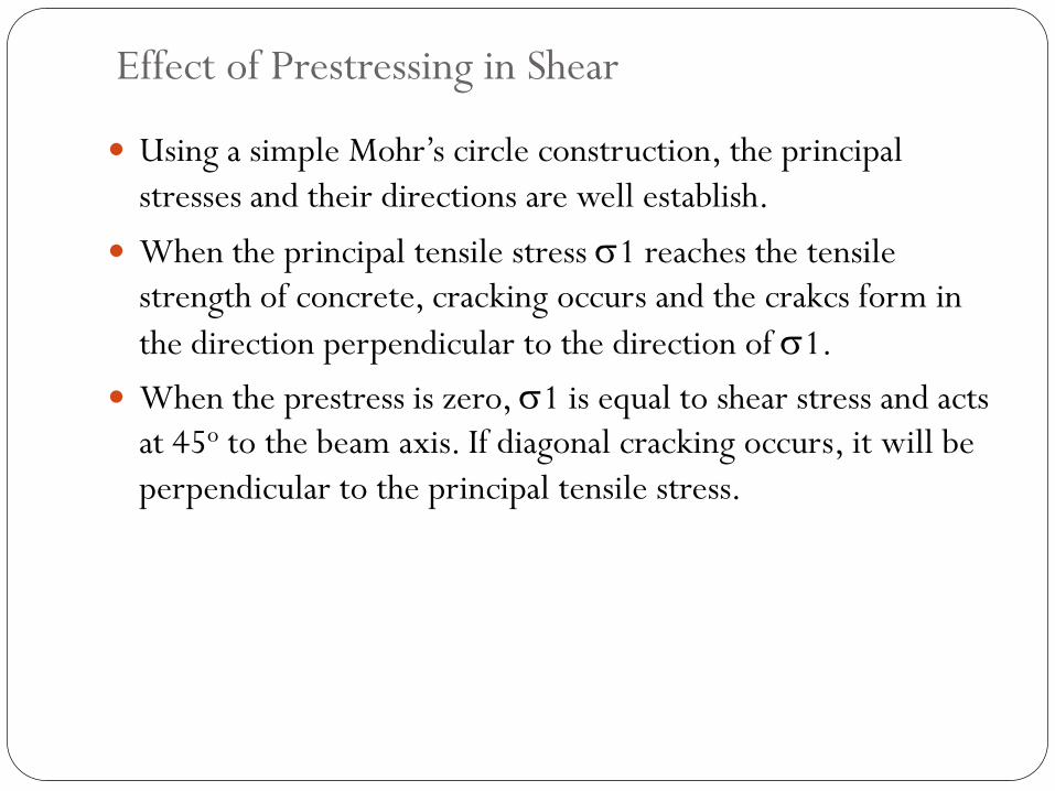
Using a simple Mohr’s circle construction, the principal
stresses and their directions are well establish.
When the principal tensile stress 1 reaches the tensile
strength of concrete, cracking occurs and the crakcs form in
the direction perpendicular to the direction of 1.
When the prestress is zero, 1 is equal to shear stress and acts
at 45o to the beam axis. If diagonal cracking occurs, it will be
perpendicular to the principal tensile stress.

Effect of Prestressing in Shear
When the prestress is not zero, the normal compressive stress
( = P/A) reduces the principal tension 1. the angle between
the principal stress direction and the beam axis increases and
consequently if cracking occurs, the inclined crack is flatter.
Prestress tehrefore improves the effectiveness of any transverse
reinforcement (strirrups) that may be used to increase the
shear strength of a beam.
With prestress causing the inclined crack to be flatter, a larger
number of the vertical stirrup legs are crossed by the crack and
consequently a larger tensile force can be carried across the
crack.
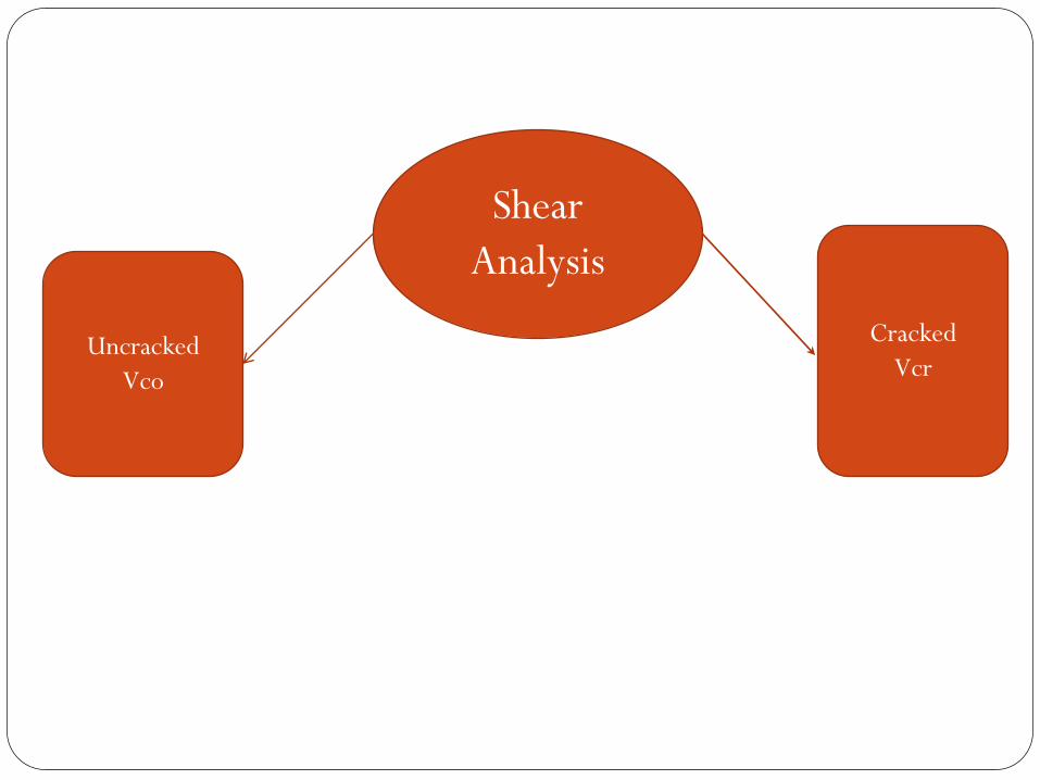
Shear
Analysis
Uncracked
Vco
Cracked
Vcr

Uncracked Sections
Small element A at the centroidal of a simply supported
prestressed concrete member subjected to compressive stress,
fcp and a shear stress, fs.
and from Mohr circle,
The allowable principal tensile stress is given in BS8110 as
For a rectangular section

Uncracked Sections
Where
Vco = design ultimate shear resistance of a section uncracked in
flexure
fcp = design compressive stress at centroidal axis due to prestress = Pe/A
ft = maximum design principle tensile stress,
bv = breadth of the member or for T, I and L beams used width of the
web
If grouted duct is present in the web
bv = bw – 0.67dd (dd = diameter of duct)

Cracked Section
Clause 4.3.8.5 BS8110 gives the following empirical equation
for the ultimate shear resistance of a section cracked in flexure:
Mo = moment which produces zero stress at extreme tension
fibre
fpt = level of prestress in concrete at the tensile face
the value of Vcr should be taken as less than 0.1bvdfcu

Cracked Section
where
m = 1.25
Should not be taken as greater than 3
Should not be taken as less than 0.67 for
members without shear reinforcement
Should not be taken as less than 1 for members with shear
reinforcement providing a design shear resistance of ≥ 0.4
N/mm2
or using Table 3.8
For characteristic concrete strengths greater than 25N/mm2, the values
in Table 3.8 may be multiplied by (fcu/25)1/3 . The value of fcu should not
be taken as greater than 40.

Design Ultimate Shear Resistance, Vc
According to Clause 4.3.8.3 BS8110
Vc = Vco at uncracked section (M < Mo)
Vc = is the smaller of Vco and Vcr at cracked section (M ≥ Mo)
For deflected tendon, the vertical component of the prstressing
will help to resist the shear force.
The total shear resistance then becomes :
Vc + Pesin where is the angle of inclination of the
prestressing tendon
For parabolic profile, e(x) = (-4/L2)x2 + (4/L)x
(x) = (-8d/L2)x + (4/L) in radian
where = abs(es – ems)

Parabolic Profile

Shear Design Steps
1. Draw the shear force and bending moment diagram
2. Check maximum allowable shear stress (Clause 4.3.8.2)
v = V/bvd 0.8fcu or 5N/mm2
3. Plot Mo on the BMD. Mo will varies along the span if the
tendon profile is not straight. Determine the cracked
(M ≥ Mo) and uncracked (M < Mo)
4. Calculate Vco and Vcr
5. Determine the ultimate shear resistance of the prestressed
beam as follows :
cracked region : Vc = Vcr or Vco + Pesin
uncracked region : Vc = Vco + Pesin

Shear Design Steps
6. If V 0.5Vc, shear reinforcement is not required (Clause 4.3.8.6)
7. If 0.5Vc < V Vc + 0.4bvd, nominal shear reinforcement is required. Refer Cl. 4.3.8.7, use
8. If V > Vc + 0.4bvd, shear reinforcement is required (Cl. 4.3.8.8). Use
dt is the depth from the extreme compression fibre either to the longitudinal bars of to the centroid of the tendons, whichever is greater.
9. Spacing of shear reinforcement, Sv the lesser of 0.75dt or 4 x web thickness, but when V > 1.8Vc, the max spacing should be reduced to 0.5dt.
10. The lateral spacing of the individual legs of the links provided at a cross-section should not exceed dt.

Example 1
A prestressed concrete T-beam shown in figure is simply
supported over a span of 28m, has been designed to carry in
addition to its own weight, a characteristic dead load of 4kN/m
and a characteristic imposed load of 10kN/m. The beam is pre-
tensioned with 14 nos 15.7mm diameter 7-wire super strands
(Aps = 150mm2) but due to debonding only 7 of the strands are
active at a section 2m from support. The effective prestressing
force, Pe for these 7 strands is 1044kN. Use the following data:
fcu = 50 N/mm2, A = 5.08 x 105 mm2, I = 134x109 mm4,
y2 = 912mm, fpu = 1770 N/mm2, fyv = 250 N/mm2,
Design the section for shear.


Solution
1. Loads
Selfweight, Wsw = 24 kN/m3 x 0.508 m2 = 12.19 kN/m
Ultimate load, W = 1.4(12.19 + 4) +1.6(10) = 38.67 kN/m
2. Shear and moment at 2m from support
V (x) = W(0.5L-x)
V(2) = 38.67 (0.5x28 – 2) = 464 kN
M(x) = 0.5W(Lx – x2)
M(2) = 0.5x38.67 (28x2 – 22) = 1005 kNm

Solution
Calculate Mo
e = 814mm, d = 1500-98 = 1402mm
< M = 1005 kNm
Section is cracked in flexure

Solution
Calculation of Vco

Solution
Calculation of Vcr
… Ok
Use 400/d = 1
fcu = 50 N/mm2 > 40 N/mm2 ; use fcu = 40 N/mm2
520 kN
And Vcr > 0.1bvdfcu = 174 kN … ok

Solution Shear resistance provided by the concrete, Vc
Vc = smaller between Vco (420 kN) and Vcr (520 kN)
Vc = 420 kN
Design of shear reinforcement
V = 464 kN , 0.5Vc = 210kN , Vc +0.4bvd = 518 kN
Where 0.5Vc < V < Vc +0.4bvd
Only nominal links required
Using 10mm diameter stirrup/links, Asv = 157mm2
< 0.75dt = 0.75(1500-98) = 1051.5mm
Use R10-450mm c/c


Example 2
The beam shown below supports an ultimate load, including
selfweight of 85kN/m over a span of 15m and has a final prestress
force of 2000kN. Determine the shear reinforcement required.
Use the following data:
fcu = 40N/mm2, A = 2.9 x 105 mm2,
I = 3.54 x 1010 mm4 , Aps = 2010 mm2, fpe/fpu = 0.6

Solution
Draw BMD and SFD
M(x) = 0.5w(Lx-x2) & V(x) = w(0.5L – x)
Where w = 85 kN/m
Check maximum allowable shear stress (Cl. 4.3.8.2)
V = 637.5 kN
< 0.8fcu or 5 N/mm2 … OK

Solution
Plot Mo on BMD
Mo vary along the length of beam since the tendon profile is
parabolic which produce the different eccentricity along the
length of beam.
Eccentricities of tendon along parabolic tendon profile given by:
Where = 425mm

Solution
Distribution of M and Mo along beam span


Variation of V along beam span

Solution
Nominal Shear Reinforcement
Use R8,
Shear reinforcement
< 0.75dt =0.75(908) = 681mm
Use R8 – 350 mm
V-Vc = 107.12 kN
< 0.75dt =0.75(772) = 579mm
Use R8 – 150 mm