Design for Durability - TII Publications · Design for Durability October 2001 ... design of...
42
Volume 1 Section 3 Part 7 NRA BD 57/01 Design for Durability October 2001 St. Martin’s House, Waterloo Road, Dublin 4. Tel:+353 1 660 2511 Fax +353 1 668 0009 Email : [email protected] Web : www.nra.ie
Transcript of Design for Durability - TII Publications · Design for Durability October 2001 ... design of...

Volume 1 Section 3 Part 7
NRA BD 57/01
Design for Durability
October 2001
St. Martin’s House, Waterloo Road, Dublin 4. Tel:+353 1 660 2511 Fax +353 1 668 0009Email : [email protected] Web : www.nra.ie

Summary:
This Standard sets out the requirements for the design of bridges in order to improve their durability.
Published by National Roads Authority, Dublin 2001
NRA DESIGN MANUAL FOR ROADS AND BRIDGES
October 2001
VOLUME 1 HIGHWAY STRUCTURES: APPROVAL PROCEDURES AND GENERAL DESIGN SECTION 3 GENERAL DESIGN Part 7 NRA BD 57/01 DESIGN FOR DURABILITY Contents Chapter 1. Introduction 2. Factors Affecting Durability 3. Improved Durability – The Conceptual Stage 4. Improved Durability – Problem Areas 5. Improved Durability – Detailed Requirements 6. Detailed Requirements – Steel Bridges 7. References 8. Enquiries

NRA DESIGN MANUAL FOR ROADS AND BRIDGES
October 2001

National Roads Authority Volume 1 Section 3 Design Manual for Roads and Bridges Part 7 NRA BD 57/01
October 2001 1/1
1. INTRODUCTION General 1.1 It has been found that the durability of many bridges in the National Roads Authority’s stock has been limited by decisions made at the design stage in relation to the bridge configuration and the choice of details. These decisions were often limited to a design philosophy in which minimising the initial capital cost was paramount. The National Roads Authority is keen to promote the concept of design for durability, thereby shifting the emphasis to a lowest whole-life cost design philosophy. 1.2 Where this Standard is applied for the design of precast concrete elements which are procured through a contract incorporating the National Roads Authority Specification for Road Works, products conforming to equivalent standards and specifications of other member States of the European Economic Area will be acceptable in accordance with the terms of the 104 and 105 Series of Clauses of that Specification. Any contract for the procurement of precast concrete elements, which does not include these clauses, must contain a suitable clause of mutual recognition having the same effect regarding which advice should be sought. Mandatory Sections 1.3 Sections of this document, which form part of the standards the National Roads Authority expects in design, are highlighted by being contained in boxes. These are the sections with which the Design Organisation must comply or must have agreed a suitable Departure from Standard with the National Roads Authority. The remainder of the document contains advice and enlargement, which is commended to designers for their consideration. Departures from Standards 1.4 In exceptional situations, the National Roads Authority may be prepared to agree to a Departure from Standard where the standard is not realistically achievable. Design Organisations faced by such situations and wishing to consider pursuing this course shall discuss any such option at an early stage in design with the National Roads Authority. Proposals to adopt Departures
from Standard must be submitted by the Design Organisation to the National Roads Authority and formal approval be received before incorporation into a design layout. The Designer shall record the fact that a Departure has been used in the design and the corresponding reasons for its use. The record shall be contained in the Preliminary Approval and the Certificate in accordance with NRA BD 2 (NRA DMRB 1.1.1A). Background 1.5 Feedback from the inspection and maintenance of road structures has highlighted durability problems even where materials, specification and construction practices have been satisfactory. These problems can often be linked to a design philosophy in which minimising the initial cost was paramount. Inadequate consideration may have been given to the long-term performance of the structure either in the choice of structural form or in the design of construction details. This has, in too many cases, resulted in maintenance problems requiring costly repair. Consequently, the National Roads Authority is keen to promote the concept of design for durability, thereby shifting the emphasis to a lowest whole life cost design philosophy. Definitions of Serviceability and Durability 1.6 Serviceability is the ability of structures to fulfil, without restriction, all the needs which they are designed to satisfy. In the design of a road structure, these needs include: i) the ability to carry without restriction all
normal traffic permitted to use the structure; ii) maintenance of user safety by provision of
adequate containment, separation of classes of users, effective evacuation of surface water etc.;
iii) maintenance of user comfort by avoiding excessive deflections, vibrations, uneven running surfaces, etc.;
iv) avoidance of public concern caused by excessive deflections, vibrations, cracking of structural elements, etc.;
v) maintenance of acceptable appearance by avoiding unsightly cracking, staining, deflection etc.
National Roads Authority Volume 1 Section 3 Design Manual for Roads and Bridges Part 7 NRA BD 57/01
October 2001 1/2
1.7 In the design of structures, however, the first of the above needs is supplemented by a separate check on the maximum load carrying capacity, known as the ultimate limit state. The ability to carry abnormal vehicles is also a need, which the National Roads Authority’s new structures must satisfy, but the occurrence of such loading is deemed infrequent and not relevant to the maintenance of the structure’s serviceability. 1.8 Durability is the ability of materials or structures to resist, for a certain period of time and with regular maintenance, all the effects to which they are subjected, so that no significant change occurs in their serviceability. In the design of road structures, the target period during which structures must remain durable, corresponds to the design life as defined in BS 5400: Part 1. 1.9 Durability is influenced by the following factors: i) design and detailing; ii) specification of materials used in construction; iii) quality of construction. 1.10 The control of items (ii) and (iii) is achieved through the use of accepted standards and procedures. However, the design of structures is not so readily associated with the achievement of durability, beyond such considerations as cover to reinforcement, crack width limitation or minimum steel plate thickness. This lack of attention to the durability aspect of design has resulted in premature loss of serviceability in many road structures. Purpose 1.11 The purpose of this Standard is to give requirements which, when used in conjunction with the existing framework of the National Roads Authority’s design standards for road structures, will improve the durability and minimise the whole-life costs of new structures. Scope 1.12 The requirements of this Standard apply to the design of all the National Roads Authority’s bridges including their retaining walls and abutments. It is not applicable to pipe bridges and sign and signal gantries. However, many of the principles may be applied to such structures.
1.13 This Standard considers various ways in which the design can contribute to the durability of a structure and identifies aspects of structural form and details, which require special attention. Many items covered in this document are acknowledged by designers as being good practice but their use has not been as widespread as would be desirable. Certain aspects of specification of materials, construction practices, inspection, and maintenance relating to durability, which is dealt with in more detail in the NRA Specification for Road Works and Notes for Guidance, are also briefly mentioned. 1.14 It should be emphasised that this Standard is not comprehensive. Designers should use their judgement and experience to ensure that durability aspects are catered for adequately in new structures. 1.15 The figures incorporated in this Standard are only indicative. Designers should satisfy themselves as to the suitability of the suggested details to specific designs. Implementation 1.16 This Standard should be used forthwith for all schemes for the construction and/or improvement of national roads. The Standard should be applied to the design of schemes already being prepared unless, in the opinion of the National Roads Authority, application would result in significant additional expense or delay progress. In such cases, Design Organisations should confirm the application of this Standard to particular schemes with the National Roads Authority. 1.17 It is the responsibility of the Design Organisation to prepare designs, which will be durable. This applies both in the overall concept and in the details of the design. Designs shall either comply with the requirements of this Standard, or contain alternative provisions, which will ensure adequate durability. Enforcement 1.18 Where reference is made in the Standard to “adequate”, or “suitable” provisions, the National Roads Authority shall determine whether the requirements of this Standard have been met. In this regard, the decision of the National Roads Authority is final.

National Roads Authority Volume 1 Section 3 Design Manual for Roads and Bridges Part 7 NRA BD 57/01
October 2001 2/1
2. FACTORS AFFECTING DURABILITY General 2.1 A survey of 200 concrete road bridges, ‘The Performance of Concrete in Bridges’, commissioned by the UK Department of Transport, identified a number of factors which contributed to the inadequate durability of many of the UK Highway Agency’s structures. Most of them were in areas where amendments to existing specification requirements, or to inspection and maintenance procedures, should provide improved durability of structures in the future. The most important of these are briefly discussed below. However, there are a number of important aspects relating to durability, which need to be addressed by improvements in conceptual design or in design detailing; these topics are often not adequately dealt with in BS 5400, and are discussed further in this document. Drainage, Joints and Waterproofing 2.2 By far the most serious source of damage is salty water leaking through joints in the deck or service ducts, and poor or faulty drainage systems. Of crucial importance is the provision of a positive, well designed, detailed and constructed drainage system. Particular attention should be given to detailing through deck drainage, and to ensure that all systems can be adequately maintained. Work undertaken by the UK’s Highways Agency and the County Surveyor’s Society and published by the Transport Research Laboratory provides detailed guidance on water management, and designers are strongly advised to consult this document (TRL Application Guide 33). Advice on the design of expansion joints is given in Chapter 5 and methods of eliminating deck joints are suggested in Chapter 3. 2.3 Also of crucial importance is the provision of an effective waterproofing system on the bridge deck. The most important properties of an effective waterproofing system are its waterproofing ability and its bond to the deck. It should be noted that if bonding is effective over the whole deck area, then any local lack of water tightness in the waterproofing layer is incapable of causing significant damage to the deck. Further advice is given in Chapter 5. Reference should also be made to BD 47 (DMRB 2.3.4), Waterproofing and Surfacing of Concrete Bridge
Decks. Advice is also given in BA 47 (DMRB 2.3.5). 2.4 An observed source of damage in road structures is the splashing or spraying of salty water from de-icing salts on to bridge abutments, piers, parapet edge beams and deck soffits. Advice is given in Paragraphs 5.2, 5.3 and 5.27 on the provisions of additional concrete cover to reinforcement and impregnation to waterproof these areas. Workmanship 2.5 A number of aspects of poor workmanship in concrete bridges were highlighted in The Performance of Concrete in Bridges. The most critical of these, from the point of view of durability, was the failure to achieve the specified concrete cover to steel reinforcement. This was found to be an extremely frequent problem, and was the cause of a great deal of deterioration, especially when it occurred in association with joint leakage etc. For further advice on concrete cover, see Paragraphs 5.2 and 5.3. 2.6 Curing of concrete is probably the second most critical aspect of workmanship revealed by the survey. The vital role of curing in providing a dense concrete cover to the steel reinforcement cannot be emphasised too strongly (especially in relation to high strength concrete). Problems of poor compaction, honeycombing, etc. were in themselves less significant, although they might compound the effects of other inadequacies. Compliance with the NRA Specification for Road Works should eliminate these problems in future. Cracking 2.7 It has been found that cracking due to early thermal effects can be a widespread problem. For advice on this, see Paragraph 5.4. 2.8 Cracking and damage due to Alkali Silica Reaction/Alkali Aggregate Reaction (ASR/AAR) were found to be rare (IEI/ICS, 1991).

National Roads Authority Volume 1 Section 3 Design Manual for Roads and Bridges Part 7 NRA BD 57/01
October 2001 2/2

National Roads Authority Volume 1 Section 3 Design Manual for Roads and Bridges Part 7 NRA BD 57/01
October 2001 3/1
3. IMPROVED DURABILITY – THE CONCEPTUAL STAGE
General 3.1 The type of structure selected for a particular location can have an important bearing on its durability. This chapter looks at certain types of construction, which have performed well, and considers their significance from the point of view of durability. Structural Continuity 3.2 Continuous structures have proved to be more durable than structures with simply supported decks, primarily because deck joints have allowed salty water to leak through to piers and abutments. In principle all bridges should, therefore, be designed as continuous over intermediate supports unless special circumstances exist. Such continuity may be either full continuity of the whole deck structure or partial continuity of, usually, the deck slab alone. 3.3 There are serious inspection, construction and maintenance problems associated with in-span discontinuities, generally referred to as ‘half-joints’. Half-joints shall not, therefore, be provided in bridge decks unless the agreement to a Departure from Standard is obtained from the National Roads Authority. 3.4 In principle, bridges with lengths not exceeding 60m and skews not exceeding 30º should, in addition, be designed as integral bridges, with abutments connected directly to the bridge deck without movement joints for expansion or contraction of the deck. Where the Designer considers that either this form of construction, known as ‘integral construction’, or a continuous structure is not appropriate, articulated construction may be used by obtaining agreement for a departure from the National Roads Authority. For instance, articulated construction may be appropriate where large differential settlements are anticipated or where an exceptionally high-end restraint could result in unacceptable stress or deformation in the deck.
3.5 Where clearance considerations permit, structures of the buried type shall be considered for all bridges. However, it should be noted that for longer bridges, the cost penalties of the use of buried structures may exceed their benefits. In doubtful cases, the National Roads Authority will adjudicate whether normal or buried construction is preferable. Continuous Bridge Decks and Integral Abutments 3.6 Traditionally, simply supported bridge decks have been used in areas where large settlements, such as those due to compressible soil strata or mining, were likely to be a problem. In view of the durability problems associated with deck expansion joints, consideration should be given to the use of continuous structures even where large differential settlements are anticipated. Due allowance should be made for the predicted movement, including lifting (i.e. hogging) off bearings, in the design of deck elements. The degree of settlement, which can be accommodated in continuous structures, must be evaluated in each case. Where these effects cannot be catered for using full continuity, partial continuity should be considered, as described in Paragraph 3.10. The ability of continuous bridge decks to accommodate differential settlements is enhanced by the use of increased span/depth ratios, but care should be taken to avoid excessive liveliness, which may be induced by the use of very slender decks. Continuous Decks Using Precast Prestressed Beams 3.7 There are two ways in which multi-span decks can be made continuous, thereby reducing deck joints: incorporating either full or partial continuity at intermediate supports. Partial continuity is achieved by providing continuity to the deck slab only, whereas full continuity involves the provision of fully continuous main beams or girders. In the case of reinforced concrete structures, post-tensioned prestressed
National Roads Authority Volume 1 Section 3 Design Manual for Roads and Bridges Part 7 NRA BD 57/01
October 2001 3/2
structures and structural steel members, this poses no particular problem of design or detailing. In the case of composite bridge decks using precast prestressed beams, the achievement of full continuity involves providing in-situ concrete over supports to the full depth of the beam and slab, which must allow for the long-term effects of prestress-induced deflection in full-continuity construction. 3.8 Figures 3.1 to 3.5 show five types of continuity construction, which have been used in the UK and have performed satisfactorily. These details may be modified for use with structural steelwork. Continuity details other than those shown may also be used providing the Designer is satisfied with their past performance. 3.9 Types 1, 2 and 3 (Figures 3.1, 3.2 and 3.3) have in-situ integral crossheads, which may be designed to develop full continuity moments. Type 2 has been used extensively in North America and details of this method of construction can be found in available literature (NCHRP, 1990, and CBDG, 1997). 3.10 Types 4 and 5 (Figures 3.4 and 3.5) provide partial continuity through the deck slabs only. They are not designed to develop the full live load continuity moment, but rather to eliminate expansion joints between each span and to transmit longitudinal forces. In the Type 4 detail, the various relative rotations and deflections at the support positions are accommodated within the connecting slab elements. This approach retains the simplicity and economy of simply supported construction whilst obtaining the various advantages of deck slab continuity. The Type 5 detail, on the other hand, does not accommodate support rotations and could be susceptible to cracking. These methods can be modified for use in composite bridge decks with steel beams. A joint detail similar to that shown in Figure 3.4 has been promoted in the UK by Kumar (1988a & b). Integral Abutments 3.11 As an extension to the concept of deck continuity, bridges can be designed with abutments connected to the bridge deck without movement joints for expansion or contraction of the deck. This form of construction, known as ‘integral construction’, should be adopted in all
cases where predicted relative settlements are sufficiently small to allow it, and where bridge spans are not too long to incur unacceptable problems in the design of the structure for thermal effects. It should be noted that the National Roads Authority’s present bridge stock contains bridges of this type having overall lengths of up to 60m. In these situations, both bearings and expansion joints can be eliminated and maintenance requirements reduced. 3.12 In designing a bridge with integral abutment walls, the load effects due to temperature changes, shrinkage and creep should be considered in conjunction with soil/structure interaction. 3.13 When using integral (portal type) abutments at the ends of long, including multi-span, bridges, thermal and other movements may be large enough to induce passive earth pressures behind the abutment walls, especially near the top. Although the design against these pressures may result in costly, heavily reinforced sections, they are still preferable to the use of conventional expansion joints, and give much less trouble in service. There are some benefits in using slender abutment walls (“balanced” design), because flexure of the walls tends to relieve the earth pressure behind them. Further guidance on the design of integral bridges is provided in BA 42 (DMRB 1.3.12), The Design of Integral Bridges. As a variation, so called “semi integral” bridges have been built which have the advantages of the elimination of deck surface expansion joints, but may retain bearings, and tend to minimise soil structure interaction effects. However, they require careful detailing to overcome potential future maintenance problems. Run-on slabs have also been used in the past, and have some advantages in spanning some areas of potential settlement of structural backfill behind the abutment. However, they have tended to produce ongoing maintenance problems when they have cracked, titled or collapsed through loss of support on the approach embankment. It has been found that “making up” a road pavement has generally been easier and less expensive where bridges have not used run-on slabs. On balance, run-on slabs are not generally recommended, although where it is essential to use them, careful design and construction is necessary. 3.14 In North America, multi-span continuous bridges with integral bank seats or short abutment

National Roads Authority Volume 1 Section 3 Design Manual for Roads and Bridges Part 7 NRA BD 57/01
October 2001 3/3
walls are frequently used. A typical arrangement of this type of integral construction is shown in Figure 3.6 and more details can be found in literature (NCHRP, 1990, and CBDG, 1997). Buried Structures 3.15 Rigid buried concrete box construction, which is an extension of portal frame construction, may be preferable to a simply supported or a portal frame type structure for short span bridges. Flexible designs incorporating corrugated steel buried structures may be suitable, except in “Very-Aggressive” exposure conditions as defined in BD 12 (DMRB 2.2.6). In general, buried structures have important maintenance and durability advantages over conventional bridge structures. Being remote from the immediate road construction, they are less sensitive to all road influences, although if a road passes through a buried structure, then the internal surfaces would be directly subjected to the effects of de-icing salts. Where conditions are suitable, their use is recommended. However, the implications from specific issues affecting the durability of buried structures (e.g. sulphate and thaumasite attack) must be considered where appropriate (see BS 5328: Part 1 and DETR, 1999). 3.16 BD 31 (DMRB 2.2.12) gives the requirements for the design of rigid buried concrete box type structures including waterproofing, joint sealants and durability considerations. 3.17 All structures must have a 120 year design life. In the case of corrugated steel buried structures a combination of sacrificial steel thickness, galvanising and secondary protective coatings must be provided to achieve the design life. Where the corrugated steel structure carries water or effluent, reinforced concrete invert protection, or an alternative, with a 120 year design life must be provided. BD 12 (DMRB 2.2.6) gives the requirements for the design of buried corrugated steel structures, including protective coatings, invert protection and corrosivity classification of the surrounding soil, groundwater and carried water. Box Sections 3.18 The size of box sections in bridge decks, abutments and piers should be such that proper
inspection and maintenance can be carried out within the box. Statutory provisions for access are contained in the Factories Act 1955. This may dictate the minimum practical size of box sections. The minimum sizes of access openings required by the Act, or by other requirements, should be treated as absolute minima; wherever possible substantially larger openings should be provided. Further recommendations are provided in Paragraph 5.18(g). 3.19 If voids are too small to afford reasonable access, exceptional care must be taken to ensure that they are adequately sealed and free from other durability problems. Consideration may be given to the use of foamed concrete, polystyrene void formers or other means to fill voids, subject to dead load and other design constraints. Such voids should, however, be provided with adequate drainage holes. 3.20 In catering for ventilation it is highly desirable, and often possible, to incorporate a level of natural illumination within boxes so that inspection is not totally reliant on artificial lighting. Plain Concrete 3.21 When designing concrete structures, consideration shall be given to all possible means of reducing or eliminating the use of corrodible reinforcement. This includes the use of plain (mass) concrete for abutments, wing walls and retaining walls, and the use of arch structures where ground conditions permit. In the case of cantilever retaining walls where reinforcement is required in one face only, consideration should be made to omitting reinforcement on the front face. Where the benefits of using plain concrete are marginal, the National Roads Authority will adjudicate whether plain or reinforced concrete shall be used. 3.22 The requirements of BS 5400: Part 4, Clause 7.5.9, and of BD 28 (DMRB 1.3), need not apply to plain concrete structures, provided that they are suitably clad or treated to conceal thermally-induced cracking. The fixings of any cladding elements shall be made using non-corrosive materials. 3.23 As ferrous reinforcement is susceptible to durability problems, consideration should be

National Roads Authority Volume 1 Section 3 Design Manual for Roads and Bridges Part 7 NRA BD 57/01
October 2001 3/4
given to the use of masonry or plain concrete construction by the choice of suitable types of structure. 3.24 Plain concrete or masonry arch structures may be feasible in some locations. In plain concrete arch structures, the need for reinforced cantilevered spandrel walls may be avoided by using mass concrete infill over unreinforced arch vaults. Options open to designers include the use of precast unreinforced voussoirs (with or without natural stone facing), unreinforced concrete arches incorporating shrinkage reducing additives and similar structures with proprietary or other crack inducers at quarter points. Some designers have also constructed concrete arches using dispersed non-ferrous fibres. 3.25 External cladding may be necessary to mask any unsightly cracking due to early thermal effects. The fixing of such cladding should be done using corrosion resistant materials of proven durability, for instance stainless steel, bronze or glass fibre inserts. 3.26 Where possible, the detailing of cladding systems should be such that cladding panels can easily be removed for the purpose of Special Inspections of the structure, or for maintenance work. Non-ferrous Reinforcement 3.27 As an alternative to the above, the control of early thermal cracking in plain concrete sections may be achieved by using corrosion resistant reinforcement. The stresses in such reinforcement may be calculated using short-term properties of the materials and ignoring the phenomenon of long-term loss of strength through creep. Creep is often significant with such reinforcement but is not considered relevant to the control of early thermal cracking, which is reasonably short term. 3.28 For the design of primary structural members, the use of non-ferrous reinforcement such as glass or aramid fibres in resin matrix may, in due course, provide a significant improvement in the durability of reinforced and prestressed concrete structures. Non-ferrous reinforcement may also be suitable in some situations, particularly in vulnerable concrete sections and inaccessible locations, which may be prone to
unseen deterioration. However, there is comparatively little published research currently available, although there are standards being developed in the United States and elsewhere. Any proposed use would require careful design consideration from first principles. It would be appropriate to consider these applications in whole life cost terms. Access 3.29 Adequate provision for access shall be made for the following purposes:
a) cleaning and painting;
b) maintenance;
c) jacking, removal/replacement of bearings;
d) inspection of closed cell and box members. 3.30 In providing such access, all the requirements of the Health and Safety legislation and other relevant requirements shall be fully observed; provision for access in excess of the minimum requirements shall be adopted wherever possible. 3.31 Public use of any of the access facilities provided for bridge inspection and maintenance shall be prevented by the provision of suitable barriers, covers, etc. Colonisation of accessible areas by plants, animals and birds shall be discouraged by suitable measures. This does not affect the possible specific provision of bird or bat boxes, etc. for nature conservation and related purposes, but such provision shall be consistent with the need to keep all access areas clean and free of debris. 3.32 Abutment galleries shall be provided below all bridge deck expansion and rotational joints. The width and headroom clearance of galleries shall preferably be at least 1000 x 1800mm respectively, and shall never be less than 800 x 1500mm. All abutment galleries shall be provided with adequate permanent ventilation to the outside atmosphere, and an adequate level of natural illumination, usually via the ventilation.
National Roads Authority Volume 1 Section 3 Design Manual for Roads and Bridges Part 7 NRA BD 57/01
October 2001 3/5
Inspection and Maintenance 3.33 When considering structural forms, details and any relevant aspects in the design procedures, designers should ensure that the structure, as well as its components, can be maintained effectively. Early identification of durability problems by inspection should prevent severe and costly damage to a structure. Areas, which are likely to be affected by de-icing agents or other corrosive elements, must be accessible for inspection and, where necessary, be designed and detailed to allow for repair or possible replacement. BA 35 (DMRB 3.3) provides further details. 3.34 It is often cost-effective to incorporate facilities for routine inspection and maintenance in a structure. In providing access, the general objective should be to give the inspector a dry, comfortable and pleasant environment in which to work. Experience has shown that, where access is difficult and where working spaces are cramped, badly lit and ventilated, damp or otherwise uncomfortable to work in, inspection tends to be less frequent and the inspector’s observational efficiency may be significantly impaired. 3.35 The following provisions for access should be made at the design stage:
a) Access for cleaning, maintenance and painting;
b) Access to parts that may require maintenance or replacement during the life of the bridge, for instance, bearings, joints, anchorage locations, drainage, pipes, manholes, lubrication of moving parts, lighting systems, etc.;
c) Access for jacking at bearings and for their removal and replacement;
d) Access to closed cells or box sections. 3.36 Access points should preferably be at each end of the structure at points which are easily accessible and do not require traffic control. Access shall be provided below deck level to avoid access through deck surfaces. Means of access could include gantries, walkways, scaffolding ladders, rails or ‘cherry pickers’. However permanent or semi-permanent facilities such as gantries require careful consideration, and assessment in whole life cost terms. They have considerable implications for Health and Safety
issues and require testing facilities and trained staff to operate them. Bridge Abutment Galleries 3.37 Abutment details such as those shown in Figure 3.7 create inaccessible areas which are vulnerable to concrete contamination by de-icing salts through leakage at joints, and are difficult to inspect and maintain. In Paragraph 3.11, the use of integral abutments is recommended wherever possible, for new designs. However, there will still be some locations where articulation at the ends of bridge decks is necessary. In such cases abutment galleries should be provided to facilitate inspection and maintenance of both rotational as well as expansion joints, bearings, abutment curtain walls and deck ends. A typical arrangement of an abutment gallery is shown in Figure 3.8. 3.38 Abutment galleries can be useful for the discharge and maintenance of drainage pipes through bridge decks and waterproofing to relieve water pressure within surfacing at joints. The incorporation of drainage systems should be considered at the conceptual design stage and not bolted on as an afterthought. 3.39 Abutment galleries may also assist bridge maintenance by facilitating access for future deck jacking. In mining areas, ground movement can close bridge expansion joint gaps and the provision of abutment galleries should reduce the extent of any remedial works necessary to free such joints. 3.40 Access to abutment galleries will be possible in some bridges between or alongside deck beams. Entry can also be arranged in some cases via secure lockable doors in abutments or wing wall faces. Access through decks should be avoided as it can create hazards and cause maintenance problems. Abutment galleries in most bridges will be permanently ventilated between bearings. Where this is not the case, ventilation should be provided, particularly if gas mains exist or are likely to be present in the vicinity of the bridge.

National Roads Authority Volume 1 Section 3 Design Manual for Roads and Bridges Part 7 NRA BD 57/01
October 2001 3/6
Proprietary Manufactured Structures 3.41 When a proprietary manufactured structure is to be provided by the Contractor, the maintenance policy for the structure shall be included in the Application for Preliminary Approval in accordance with NRA BD 2 (NRA DMRB 1.1.1A). Foundations and Buried Concrete Structures 3.42 To ensure that foundations and other buried concrete structures are durable, it is essential to ensure that the ground conditions are thoroughly investigated. It is important to correctly classify the sulphates and sulphides present in the soil and groundwater. All new buried or partially buried concrete construction should comply with the requirements of the DETR publication “The Thaumasite Form of Sulfate Attack. Risks, Diagnosis, Remedial Works and Guidance on New Construction” (1999). This document contains recommended measures, which will minimise the risks of all forms of sulphate attack. The measures include the control of concrete mixes, together with additional protection, and using a risk-based strategy, depending on the structural performance level required. Road structures requiring a 120-year design life shall be classed in the “High Performance Level”. Where shorter design life is required, lower performance levels may be considered at the discretion of the National Roads Authority. Steel Sub-structures and Buried Steel Structures 3.43 Exposed steel sheet piling in permanent construction for bridge abutments and retaining walls, and buried corrugated steel structures, require careful design and detailing to ensure that the 120 year design life required for road structures is achieved. The design life of these types of structure is obtained primarily by providing additional sacrificial thickness to the steel sections. In order to ensure that these types of structure are appropriate for the exposure conditions and that the correct sacrificial thickness is provided, it is essential to investigate thoroughly the soil and groundwater conditions. It is important to identify correctly the concentrations of chlorides, sulphates and
sulphides and the acidity of the ground. In the case of chlorides, it may be necessary to allow for higher concentrations caused by the accumulation of de-icing salts in the ground over time. Steel sub-structures and buried corrugated steel structures may not be suitable in very aggressive environments, such as where there is direct or indirect exposure to de-icing salts, within tidal zones of watercourses, where ground is acidic or alkaline, and other similarly aggressive conditions.

National Roads Authority Volume 1 Section 3 Design Manual for Roads and Bridges Part 7 NRA BD 57/01
October 2001 3/7
Figure 3.1: Continuity Detail Type 1 – Wide In-situ Integral Crosshead Typical Features:
1. Beams are erected on temporary supports, generally off pier foundations.
2. Permanent bearings are in a single line.
3. Continuity reinforcement is provided in the slab and at the top and bottom of bridge beams. The lapping of reinforcement is normally not difficult.
THIS FIGURE IS ONLY INDICATIVE

National Roads Authority Volume 1 Section 3 Design Manual for Roads and Bridges Part 7 NRA BD 57/01
October 2001 3/8
Figure 3.2: Continuity Detail Type 2 – Narrow In-situ Integral Crosshead Typical Features:
1. Temporary supports are not required.
2. Permanent bearings may be in single or twin line.
3. Continuity reinforcement is provided in the slab and at the bottom of bridge beams. The lapping of reinforcement is difficult.
THIS FIGURE IS ONLY INDICATIVE

National Roads Authority Volume 1 Section 3 Design Manual for Roads and Bridges Part 7 NRA BD 57/01
October 2001 3/9
Figure 3.3: Continuity Detail Type 3 – Integral Crosshead Cast in Two Stages Typical Features:
1. Beams are supported on Stage 1 crosshead during erection.
2. Crosshead to be monolithic with pier.
3. Crosshead soffit is normally lower than beam soffit.
4. Reinforcement is similar to Types 1 and 2, depending on the cross-section of the Stage 1 crosshead.
THIS FIGURE IS ONLY INDICATIVE

National Roads Authority Volume 1 Section 3 Design Manual for Roads and Bridges Part 7 NRA BD 57/01
October 2001 3/10
Figure 3.4: Continuity Detail Type 4 – Continuous Separated Slab
Typical Features:
1. Separate bearings and diaphragms are provided for each span.
2. Deck slab is separated from support beams for a short length to provide rotational flexibility.
3. There is no continuity reinforcement between ends of beams and there is no moment continuity between spans.
THIS FIGURE IS ONLY INDICATIVE
National Roads Authority Volume 1 Section 3 Design Manual for Roads and Bridges Part 7 NRA BD 57/01
October 2001 3/11
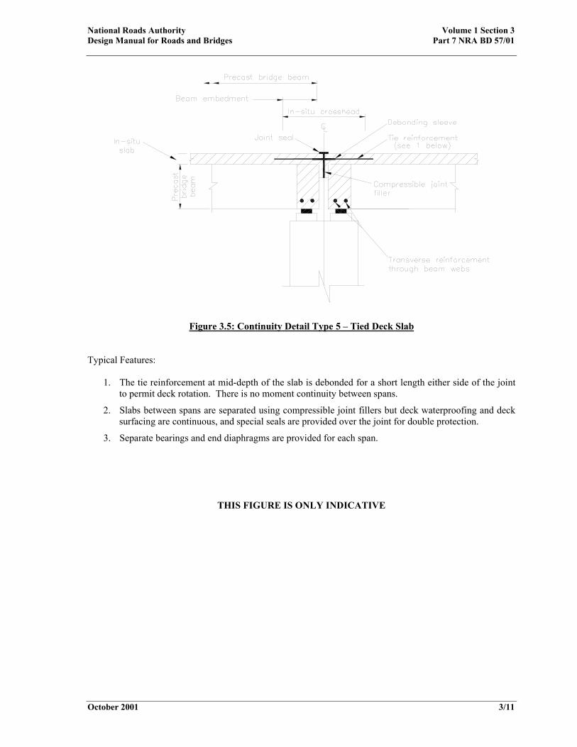
Figure 3.5: Continuity Detail Type 5 – Tied Deck Slab
Typical Features:
1. The tie reinforcement at mid-depth of the slab is debonded for a short length either side of the joint to permit deck rotation. There is no moment continuity between spans.
2. Slabs between spans are separated using compressible joint fillers but deck waterproofing and deck surfacing are continuous, and special seals are provided over the joint for double protection.
3. Separate bearings and end diaphragms are provided for each span.
THIS FIGURE IS ONLY INDICATIVE
National Roads Authority Volume 1 Section 3 Design Manual for Roads and Bridges Part 7 NRA BD 57/01
October 2001 3/12
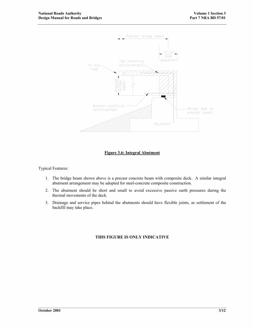
Figure 3.6: Integral Abutment Typical Features:
1. The bridge beam shown above is a precast concrete beam with composite deck. A similar integral abutment arrangement may be adopted for steel-concrete composite construction.
2. The abutment should be short and small to avoid excessive passive earth pressures during the thermal movements of the deck.
3. Drainage and service pipes behind the abutments should have flexible joints, as settlement of the backfill may take place.
THIS FIGURE IS ONLY INDICATIVE

National Roads Authority Volume 1 Section 3 Design Manual for Roads and Bridges Part 7 NRA BD 57/01
October 2001 3/13
Figure 3.7: Inaccessible Bearing Shelf (This Detail is Not Recommended)
THIS FIGURE IS ONLY INDICATIVE

National Roads Authority Volume 1 Section 3 Design Manual for Roads and Bridges Part 7 NRA BD 57/01
October 2001 3/14
Figure 3.8: Abutment Gallery
THIS FIGURE IS ONLY INDICATIVE

National Roads Authority Volume 1 Section 3 Design Manual for Roads and Bridges Part 7 NRA BD 57/01
October 2001 4/1
4. IMPROVED DURABILITY – PROBLEM AREAS General 4.1 It is apparent from recent surveys on bridges that there are some structural forms and elements, which are more susceptible to durability problems than others are. This chapter provides advice on the use of these forms and considers other areas that require special attention. Half-Joints and Concrete Hinges 4.2 Half-joints, both in steel and in concrete usually present severe maintenance problems. They are difficult to inspect and repair and should not be used for new designs unless there is absolutely no alternative. Where half-joints are used, steel and concrete surfaces should be given additional protection. Adequate provision must be made for drainage, inspection and maintenance. 4.3 Concrete hinges are highly stressed areas where, because of the amount of reinforcement present, compaction of concrete is difficult. The steel in the hinges is vulnerable to corrosion from the ingress of salty water. Concrete hinges should not be used for new designs unless there is absolutely no alternative. Where concrete hinges are used, they should be visible for inspection and maintenance. Deck hinge joints are particularly vulnerable to corrosion and they should not be used in new designs. Pre-Tensioned Prestressed Concrete Construction 4.4 Precast pre-tensioned concrete members have generally proved to be durable. Apart from concern about occasional problems, for example, horizontal cracking of the beam in the end zones, the poor performance of some bridges constructed with these members has been associated with the use of simply supported spans. Suggested remedies for this are discussed in Chapter 3. 4.5 De-bonded tendons at the ends of precast beams should be adequately protected against corrosion.
Post-Tensioned Concrete Construction 4.6 Virtually all post-tensioned bridges built to date have been of the grouted duct type. In the UK, problems have been encountered in a number of structures of this form, largely due to the vulnerability to corrosion of tendons resulting from inadequate grouting of the ducts. The reduced durability has caused particular concern since the deterioration often cannot be identified in the course of regular bridge inspections; this means that serious loss of carrying capacity may remain undetected, with consequent risk to public safety. In some instances, there may be little or no warning of collapse in prestressed bridges, and this makes the risk of undetected deterioration more serious. The NRA Specification for Road Works and the Concrete Society’s Report TR47, Durable Bonded Post-Tensioned Concrete Bridges, should be studied carefully by designers for their guidance on these matters. The detailed guidance provided should ensure that ducts are fully grouted and that post-tensioned systems are protected and will be durable. Segmental Construction 4.7 In-situ joints between precast segments are the areas most at risk from penetration by water and de-icing agents. This may lead to severe local corrosion of prestressing strands. Although new systems are currently under development to ensure continuity across the joint, and to provide greater protection, for the time being such forms of construction using internal grouted tendons are not permitted without the National Roads Authority’s prior approval. Precast concrete segmental construction using external post-tensioned systems is permitted. 4.8 Another problem, which has not been widely recognised by designers, is the additional prestress loss, for larger joint widths, due to large elastic compression and subsequent creep deformation of the joint material and closure of cracks at interfaces. As a result, the final level of prestress in segmental construction may be somewhat less than normal post-tensioned members.

National Roads Authority Volume 1 Section 3 Design Manual for Roads and Bridges Part 7 NRA BD 57/01
October 2001 4/2
4.9 It has been observed that if the compressive stress across a mortar joint is less than 2 to 3 N/mm2, the joint may show “partially cracked” section behaviour and high local strains may develop in any steel passing across the joint. There is also a likelihood of salty water entering the joint and corroding reinforcement. Deterioration of the joint is not easily detectable and failure may occur in a sudden and brittle manner. 4.10 Shortening due to shrinkage may also occur at the ends of each precast unit. This could cause additional opening at the joints prior to stressing and hence reduce the compressive stresses at the interfaces and encourage cracking. 4.11 Designers should be aware that because of water seepage through joints between segments, grouted duct prestressing in segmental construction is particularly susceptible to tendon corrosion. External Post-Tensioned Tendons 4.12 Post-tensioned tendons positioned outside the concrete have the advantage of being accessible for inspection and replacement. This must be balanced against some concerns about increased exposure and vulnerability. Where external post-tensioned tendons are used, they should be protected properly and have adequate facilities and access for inspection, maintenance and replacement. The method and sequence of cable replacement should be allowed for at the design stage and where possible designed to eliminate the necessity for traffic restrictions. It should be noted that the Concrete Society Technical Report TR47, Durable Bonded Post-tensioned Bridges, is currently being updated and is due for republication: it is intended that the report will include recommendations for best practice for external post-tensioned systems which should be adopted. Further information on design issues is available in BD 58 and BA 58 (DMRB 1.3.9 and 1.3.10). Voided Slabs 4.13 The adoption of pseudo-slab and similar structures using void formers to achieve the final cross-section has led to some serious problems,
usually related to the buoyancy of the formers during construction and the difficulty of compaction under the voids. Special precautions should be taken in the design and construction of this type of structure, such as additional cover to reinforcement adjacent to voids, adequate tying down of voids with straps that do not cut into the void formers, and close spacing of ties so as to prevent bowing of void formers. Foundations and Buried Concrete Structures 4.14 Foundations and other buried concrete structures in certain aggressive ground conditions have been found to be susceptible to sulphate attack, leading to eventual deterioration of the concrete. Although this has been judged a serviceability issue, rather than a short-term safety concern, it does have implications for long-term durability. Although buried concrete is not often or routinely inspected, most structures would be expected to exhibit above ground indications of below ground concrete deterioration, before safety was impaired. 4.15 A range of measures to minimise the risks of sulphate attack are recommended in the DETR publication “The Thaumasite Form of Sulfate Attack. Risks, Diagnosis, Remedial Works and Guidance on New Construction”. This has been implemented by the UK Highways Agency’s Interim Advice Note 25 “Measures to Minimise the Risk of Sulfate Attack (Including Thaumasite)”. The latter document includes options for concrete mixes, and additional protective measures such as coatings for buried concrete and subsurface drainage where appropriate, which will minimise the risk of all forms of sulphate attack. It is particularly recommended that vulnerable design details such as concrete hinges, joints and slender concrete sections are avoided by “designing out” such features. 4.16 Further research is under way at the Building Research Establishment and elsewhere and it is expected that BRE Digest 363 “Sulphate and acid resistance of concrete in the ground” will be updated or replaced and that it will incorporate the latest guidance to deal with aggressive ground conditions. The NRA Specification for Road Works and Notes for Guidance on the

National Roads Authority Volume 1 Section 3 Design Manual for Roads and Bridges Part 7 NRA BD 57/01
October 2001 4/3
Specification include requirements to minimise the risks of sulphate attack. Parapet Upstands 4.17 Parapet upstands are particularly vulnerable to the effects of chloride ingress, and to the possibility of freeze thaw action. In accordance with the NRA Notes for Guidance on the Specification for Road Works clause NG1703, where concrete Grade 40 is being used, then air entrainment should be adopted to increase durability. The minimum grade of concrete in parapet upstands should not be less than Grade 40. Services and Service Bays 4.18 One of the areas where there are often durability problems is in service bays. They are not easy to inspect, and are prone to leakage from ill fitting, incorrectly replaced or damaged cover slabs. Water can also enter the service bay via badly detailed or constructed concrete through deck ends and ballast walls, at joints or via the service ducts themselves. Service bays should be provided with drainage holes, and should have all exposed concrete surfaces carefully waterproofed. In general, it is not recommended to fill service bays with “lightweight fill”, but better to assume that they will leak and deal positively with the water that enters. Service bays should also facilitate access for authorised services providers. 4.19 Where possible it is recommended that drainage pipes, ducts and sleeves penetrating through bridge decks and ballast walls, should be provided with puddle flanges cast monolithically into the deck, rather than as a second operation with a concrete “box-out”. This will require extremely careful positioning of the pipe or duct, and in some cases will not be practical. Other relevant information and details are contained in TRL Application Guide 33, Water Management for Durable Bridges.

National Roads Authority Volume 1 Section 3 Design Manual for Roads and Bridges Part 7 NRA BD 57/01
October 2001 4/4
National Roads Authority Volume 1 Section 3 Design Manual for Roads and Bridges Part 7 NRA BD 57/01
October 2001 5/1
5. IMPROVED DURABILITY – DETAILED REQUIREMENTS
General 5.1 The life of a bridge can be considerably enhanced at little additional expense by sound detailing of structural elements. This chapter gives advice on aspects of detailed design, which should enhance durability. Designers should also study carefully the CIRIA Report C543 “Bridge Detailing Guide” (Soubry, 2001), which gives advice and standard details applicable to bridges and other road structures. Reinforcement Cover 5.2 In designing cast in-situ concrete and non-prestressed precast concrete members, the cover to reinforcement used in design and indicated on the drawings, shall be the nominal cover derived from BS 5400: Part 4 Table 13, increased by at least 10mm. Reinforced Concrete 5.3 This Standard increases the concrete covers to reinforcement specified in BS 5400: Part 4 Table 13. However, in sensitive or critical areas of the structure such as in the region below expansion joints, serious consideration should be given to the use of concrete covers greater than those specified in this Standard. It should be noted too that the requirements of BS 5400: Part 4, do not penalise the designer for using greater cover than the Table 13 values with respect to crack width calculations. The definition of Cnom in clause 5.8.8.2 of the BS makes it clear that the designer may ignore extra cover in calculating cracks widths. However, surface crack widths are likely to be wider as a consequence of increased cover and will therefore have aesthetic disadvantages in some locations. It should be noted that as BS 5400: Part 4 already makes provision for an additional 10mm cover for lightweight aggregate concrete, this Standard’s requirement for additional concrete cover does not apply to such concrete.
5.4 The minimum areas of main and secondary reinforcement given in BS 5400: Part 4 Clause 5.8.4 are, in many instances, not adequate to limit the cracking of concrete caused by the dissipation of heat of hydration while the concrete is immature. Designers should refer to the requirements given in BD 28 (DMRB 1.3), Early Thermal Cracking of Concrete. In designing reinforcement for early thermal effects, the designer should bear in mind that the strength and cement content of the as-built concrete may be a good deal higher than that specified on the contract drawings. As the cement content has a significant effect on the heat evolution during hydration, the temperature effects due to the likely maximum cement content should be used. 5.5 Cement replacements, such as pulverised fuel ash and ground granulated blast furnace slag, may reduce early thermal effects and improve resistance to chloride ingress, sulphate attack and Alkali-Silica Reaction (see Concrete Society Report TR40). 5.6 Where local cracking of the concrete may occur due to restraint from adjacent elements, e.g. at corners of two-way slabs, reinforcement should be detailed carefully to control such cracking. In some cases, a detailed investigation of the stresses in these areas may be necessary. Grouted Duct Post-Tensioning 5.7 The design of grouted duct post-tensioned prestressing shall comply with the requirements of NRA BD 24 (NRA DMRB 1.3.1). External Prestressing 5.8 Post-tensioned structures using external or unbonded tendons shall be detailed such that inspection of all individual tendons and their eventual replacement is possible without restricting traffic on the road. Prestressed Concrete 5.9 Anchorage of tendons in post-tensioned structures is of particular concern. Designers

National Roads Authority Volume 1 Section 3 Design Manual for Roads and Bridges Part 7 NRA BD 57/01
October 2001 5/2
should ensure that sufficient anti-bursting, spalling and equilibrium reinforcement is provided, in accordance with BS 5400: Part 4 Clause 6.7.5, and that the layout of the anchorage zone reinforcement is not congested or likely to cause difficulties in placing and compacting concrete. Sufficient concrete cover should be provided to ensure effective protection to the steel. 5.10 Post-tensioned externally prestressed structures should be detailed to facilitate replacement or re-stressing of an individual tendon, without restricting traffic flow across the bridge. The provision of special monitoring devices to detect loss of pre-tensioning or corrosion should be considered. External tendons should be positioned so that they can easily be inspected and maintained. However, this should be balanced against increased exposure and vulnerability. Drainage and Waterproofing 5.11 Systems for the drainage of surface water from bridges shall be so detailed that water is not allowed to fall freely from the bridge deck. Closed drainage systems shall be sufficiently robust to withstand damage during cleaning, as this has been an important cause of problems on many existing bridges. They shall also be resistant to damage from all commonly occurring chemical spillages on the road surface. Drainage waters from bridge decks shall never be discharged into the drainage layers behind abutments. 5.12 Access openings on bridges shall be provided with adequately sealed and properly drained hatches or covers where necessary. However, access from the upper surface of the bridge decks shall generally be avoided. Adequate ventilation and drainage holes shall be provided to all closed cell or box sections. In closed sections where access for inspection is provided, adequate provision for artificial lighting shall be made, preferably with some minimum provision for illumination by natural light. 5.13 Drainage and waterproofing play a vital role in the durability of structures. Drainage should be considered at the conceptual stage so
that pipes and road gullies can be accommodated properly in an aesthetically and maintainable way: not bolted on as an after-thought. Designers should refer to BD 47 (DMRB 2.3.4) when designing drainage and waterproofing of concrete bridge decks. BA 47 (DMRB 2.3.5) and TRL Application Guide 29, Practical Guide to the Use of Expansion Joints, also provide guidance. 5.14 The drainage of water from bridge decks and waterproofing layers should normally be done using closed systems, which lead the water positively to the main road drainage system. Allowing water from deck drainage to fall freely from open-ended downpipes should be avoided for the following reasons:
i) In windy conditions such water may become finely atomised and spray onto the structure, even when downpipes project well below the soffit line.
ii) Freely discharged water may contaminate river courses.
iii) Freely discharged water may cause local damage to the soil surface below the bridge.
iv) Water from open-ended downpipes may fall onto a carriageway or footway beneath and freeze, causing a hazard to both pedestrians and vehicles. There is also a danger that icicles may form on open ended downpipes and fall onto vehicles and pedestrians.
5.15 Drainage systems integral with the structure, for instance gullies cast into beams and pipes cast into columns, should not be used. Essential drainage runs through deck slabs should be made as short as possible. On short span bridges it may be preferable to collect surface water off the bridge deck, although this will require careful design of deck and carriageway falls and detailing, to ensure that no ponding on or beneath the surfacing occurs. 5.16 Drainage systems should be provided with adequate facilities for rodding and cleaning operations. Rodding access should be provided so that rodding lengths are straight or virtually straight, and do not normally exceed 45m on straight runs. Careful thought should be given to the practical needs of cleaning and maintenance operations, and full details provided accordingly. Designs should minimise the need for traffic
National Roads Authority Volume 1 Section 3 Design Manual for Roads and Bridges Part 7 NRA BD 57/01
October 2001 5/3
management during cleaning operations. All gullies should be fully trapped. 5.17 Drainage of bridge decks should never be directed into the drainage layers in the vicinity of piers and abutments, since salty water from the bridge deck may cause corrosion of the reinforcement in the substructure. Moreover, accumulated road silts and debris may eventually clog the drainage layers.
5.18 The durability of a bridge can be improved by taking the following precautions:
a) The top surface of bridge decks should have adequate falls to avoid ponding, especially in the vicinity of deck joints. Drainage outlets should be formed using adequately sized products, at regular intervals.
b) Additional measures, such as coating and extra waterproofing layers, etc., may be considered necessary where a concentration of de-icing agent is likely to occur.
c) Areas around kerbs, parapets and service traps are most vulnerable to water seepage and should be detailed with care.
d) Access holes should be located on the underside of bridge decks to avoid water leakage into the deck. When this is not possible, properly sealed and/or positively drained manholes may be used, but only with the agreement of the National Roads Authority.
e) Drainage should be provided at piers and abutments, including the back of abutments.
f) Holes should be provided to drain the voids of bridge decks, such as box beams and cellular and voided slabs, as water may find its way into these voids causing corrosion and deterioration.
g) Box members should be provided with sealed access hatches or manhole covers to prevent leakage into the box. Adequate and effective ventilation and drainage holes should also be provided to reduce condensation and eliminate any ponding inside the box as a result of the possible ingress of water. Ventilation and drainage
holes should be detailed to prevent access and colonisation by birds and animals.
5.19 The top surfaces of bridge decks, vertical faces at deck ends, the top surfaces of piers and abutment bearing shelves should be waterproofed with waterproofing for bridge decks in accordance with the NRA Specification for Road Works. In addition, the following concrete surfaces should be waterproofed using tar, cut back bitumen or appropriate proprietary materials as allowed in the NRA Specification:
i) Abutment curtain walls.
ii) Inaccessible areas that may be subject to leakage; for instance beam-ends.
iii) Buried concrete surfaces. Where waterproofing membranes may be subject to direct foot traffic, they must be sufficiently robust to withstand such use, and should not be slippery. Expansion Joints 5.20 Designers should refer to BD 33 (DMRB 2.3.6) when designing and detailing expansion joints and drainage provisions in bridge decks. Further guidance is also provided by BA 26 (DMRB 3.3.7), NCHRP Synthesis 141 (1989) and TRL Application Guide 29. 5.21 To prevent salty water from penetrating downwards to the substructure, expansion joints should be watertight. However, these joints will eventually leak and therefore designers should not only apply protective coating to surfaces at risk, but also provide drainage under the joints in the form of abutment galleries as described in Paragraph 3.32. 5.22 Careful detailing around expansion joints in bridge decks can make a major contribution to the durability of a structure. Failure of deck expansion joints often leads to severe corrosion of adjacent parts of the structure. The areas around a joint should be detailed in such a way that they do not provide traps for water and that an effective system is provided to remove the water quickly. All the elements should be detailed so that they are accessible for inspection and maintenance.

National Roads Authority Volume 1 Section 3 Design Manual for Roads and Bridges Part 7 NRA BD 57/01
October 2001 5/4
Splash Zones 5.23 Designers should be aware that the splash zone of river or road piers and abutments are particularly susceptible to deterioration. In some situations, salty water may be splashed up to the soffit of overbridges causing deterioration and corrosion. In addition, the spray may result in the retention of salt in the soil adjacent to the carriageway, thus causing severe chloride attack to the concrete sub-structure. Special precautions should be taken in these areas by the application of a protective coating, for instance chemical impregnation, and by the provision of additional cover to steel reinforcement (see Paragraph 5.2). Other Details 5.24 It is essential to provide drip checks at all edge beams, deck ends over abutments and other locations such as copings to retaining walls, to prevent water from running back along horizontal surfaces. Where, for reasons of concrete cover, the provision of groove type drips is not practicable, continuous unreinforced concrete downstands or continuous non-ferrous angle sections properly fixed to deck edges may be used as drippers. BA 33 (DMRB 2.4) shows a prefabricated drip strip for use on existing structures. 5.25 Bridge decks should be designed to project beyond the substructure to prevent salty water from running down columns and abutments. 5.26 The designer should always consider the ease of construction of the proposed details. For example, adequate provision should be made for compacting concrete and for painting of structural steel. Impregnation and Coating of Concrete Surfaces 5.27 Impregnation of concrete or impregnation plus coating of concrete surfaces provides effective protection against the ingress of chlorides. Requirements for impregnation procedures are given in BD 43 (DMRB 2.4) and further advice is provided in BA 33 (DMRB 2.4). Other aspects are dealt with in the NRA Specification for Road Works.
High Performance Concrete 5.28 Recent developments in concrete technology, most notably the use of cement replacement materials and superplasticisers, allowing lower water-cement ratios, enable concretes to be produced with significantly higher strengths and other improved properties such as reduced chlorine diffusion rate, lower permeability and the like (see FIB-CEB, 1990, Aitcin, 1992, Neville, 1994, and Nawy, 2001). The National Roads Authority is currently researching this area for applications to bridge design. Design Organisations are encouraged to use developments in concrete technology where these lead to improved durability and where any additional cost incurred is justified on the basis of lower whole life cost. Pulverised Fuel Ash (PFA) 5.29 PFA is an artificial pozzolan produced as a by-product of burning coal. Siliceous fly ash and calcareous fly ash (designated V and W respectively in EN197-1) may be combined with clinker, designated K (i.e., Portland cement), to produce a Portland-fly ash cement conforming to EN197. The use of PFA in concrete causes both a reduction in heat of hydration and early rate of gain of strength of hardening concrete – this property is of benefit in reducing early thermal cracking (see Concrete Society Report TR40). A minimum replacement of 25% is recommended. The pozzolanic properties of PFA contribute to an increase in the rate of strength gain at later ages. The fineness of PFA particles also contributes to greater strength by filling voids in the matrix between cement particles. Concretes containing siliceous fly ash, i.e., CEMII/A-V or CEMII/B-V to BS EN 197-1, also have reduced permeability and porosity and are, therefore, more resistant to chloride ingress, sulphate/acid attack and alkali-silica reactions (ASR), but these characteristics are highly dependent upon proper curing. Concretes containing PFA tend to have higher rates of carbonation than concrete with Ordinary Portland cement only, but this is counter balanced by reduced permeability. If air entrainment is required in concrete with PFA, then higher dosages of air entraining admixture (AEA) are necessary.
National Roads Authority Volume 1 Section 3 Design Manual for Roads and Bridges Part 7 NRA BD 57/01
October 2001 5/5
5.30 Concrete with PFA has a dark appearance (slate grey colour), so a coloured coating may need to be considered for external surfaces in order to provide a reasonable appearance. The use of concrete with PFA is recommended for consideration in foundations and below ground level where its appearance is unimportant. Ground Granulated Blastfurnace Slag (GGBS) 5.31 GGBS is produced from high-grade iron ores blended with limestone and is a cementitious material. GGBS is designated S in BS EN 197-1 and is used in the manufacture of CEM III blastfurnace cement. Concrete with GGBS has slower heat development and a lower peak temperature and, therefore, a lower early rate gain of strength compared to concrete with Ordinary Portland cement (CEM I to BS EN 197-1) (see Concrete Society Report TR40). The slower heat development is of benefit in reducing early thermal affects, especially for thick sections. The percentage replacement of the total cementitious material is generally in the range of 50% to 70%, which falls in the range covered by CEM III/A and CEM III/B cements to BS EN 197-1. Concrete with GGBS has a dense microstructure that improves long-term strength, reduces chloride ingress, reduces permeability and porosity and improves resistance to sulphate/acid attack. Furthermore, the risk of ASR is virtually eliminated regardless of alkali content or aggregate sensitivity. These characteristics are highly dependent on proper curing. As with PFA, GGBS concrete has a higher rate of carbonation but this is counterbalanced by reduced permeability. Freeze-thaw behaviour is similar to that of Ordinary Portland cement (OPC) concrete with equivalent strength and air entrainment, but generally, more AEA is required. 5.32 Concrete with GGBS should be considered for general use in bridges and other structures where appropriate. In some cases the use of surface impregnation or surface impregnation with coatings will not be necessary for concrete with GGBS, especially when combined with the use of controlled permeability formwork, higher strengths and covers or other means of improving durability. Concrete with GGBS has a light colour and a good appearance.
Silica Fume 5.33 Silica fume, also known as microsilica, is a cementitious material that is generally used as a cement replacement in the proportion 6% to 10% by weight of cementitious material. Silica fume is designated D in BS EN 197-1 and is used to make Portland-silica fume cement, which is designated CEM II/A-D. Silica fume accelerates hydration, exhibiting a higher initial water demand but reduced heat of hydration compared with concretes of equal strength with CEM I cement (see Concrete Society Report TR41). Concrete with silica fume has improved durability because of its reduced permeability, lower chloride diffusion rate, and improved resistance to sulphate/acid attack and ASR. The effect on the rate of carbonation is unchanged for low water to cementitious material ratios. Increased dosage of AEA is required for freeze-thaw behaviour comparable to OPC concretes with air entrainment. 5.34 Silica fume is considered too expensive for use as a replacement material in concretes for general use in bridge construction. However, there may be benefits in using Portland-silica fume cement in small areas or in pre-tensioned precast beams where high early strength is advantageous. The high early gain of strength of silica fume may be used to counterbalance the slower rate of gain of strength of concretes with GGBS or PFA replacements where this is necessary. Natural Calcined Pozzolana 5.35 Natural calcined pozzolana, such as metakaolin, are formed from partially burnt clays/shales and are designated Q in EN197-1. Metakaolin (calcined china clay) is a highly reactive pozzolan. The use of 5% to 10% metakaolin by weight of cementitious material (classified as CEM II/A-Q to EN197-1) can produce concretes with performance characteristics comparable with those of silica fume concretes with respect to strength development rate, chloride diffusion rate and resistance to freeze–thaw deterioration. Significantly, concretes with metakaolin do not have increased rates of carbonation, unlike GGBS and PFA concrete.

National Roads Authority Volume 1 Section 3 Design Manual for Roads and Bridges Part 7 NRA BD 57/01
October 2001 5/6
5.36 It is considered that metakaolin may be used as a cement replacement material in a similar manner to silica fume (see Paragraph 5.34). Controlled Permeability Formwork (CPF) 5.37 CPF comprises a fine fabric similar to a geotextile fabric, which lines the formwork and allows free water and air to move quickly away from the face of the concrete when it is poured and as it cures (CIRIA Report CB511). The result is to improve greatly the curing of the vital cover zone, ensuring that it is dense, has lower permeability and porosity, and is free of blow holes and other surface flaws (Price & Widdows, 1991). In addition, higher strengths are observed in the cover zone due to the reduced water/cement ratio in this region caused by migration of water and cement particles. 5.38 Whilst there are advantages in using CPF, this must be balanced against additional costs and some practical difficulties that may occur during construction, particularly with complex shapes. The current position is that CPF may be used in specific new construction situations where there are: a) Concrete elements in close proximity to
carriageways, which are heavily salted on a regular basis each winter.
b) Concrete elements having simple geometric
shapes and plain finishes. CPF must also be justified in whole life cost terms. For the time being the use of CPF will be regarded as an aspect not covered by the NRA Specification and National Roads Authority approval will be required, as part of technical approval procedures (see NRA BD 2, DMRB 1.1.1A). Stainless Steel Reinforcement 5.39 Stainless steel reinforcement complying with IS EN 10088 may also be considered for use. Austenitic and duplex stainless steels can prevent chloride-induced corrosion of reinforcement and therefore improve durability. The additional cost of using stainless steel may, to some degree, be
offset by other design changes that may save on initial construction costs without affecting durability. Over the life of the structure the use of stainless steel may be justified by the reduction in routine maintenance and repair. 5.40 Consideration should be given to the use of stainless steel in particularly vulnerable areas as outlined in Table 13 of BS 5400: Part 4. These areas include below the expansion joints, parapet edge beams, splash zones and substructures in marine environments, particularly on heavy trafficked roads that tend to be salted regularly during the winter months. For a limited number of structures, more extensive use of stainless steel throughout all the structural elements may be justified. Since this would mean that initial construction costs might be significantly greater, this approach must be supported by a detailed whole life costing, and requiring the prior approval of the National Roads Authority. 5.41 Type 1.4301 stainless steel corrodes eventually (after about 75 years) when air and moisture are available, so it is recommended that other measures, such as specifying a cement replacement such as PFA or GGBS, be adopted when using this grade. Type 1.4436 stainless steel does not require any additional measures when used with OPC concretes. Coated Reinforcement 5.42 Fusion bonded epoxy coated reinforcement (FBECR) involves coating carbon steel with a non-corrodible non-metallic coating, which protects the carbon steel from corrosion. FBECR requires extra care during handling, storage and fixing in order to keep damage to the coating within allowable limits set out in BS ISO 14654. However, there are concerns that specific concreting operations cause serious damage to the coating due to the action of vibrating pokers during compaction. Damage can occur where bars cross each other. Localised damage to coatings can lead to pitting corrosion of the reinforcement in the presence of chloride ions. 5.43 At present it is not recommended to use FBECR in concrete vulnerable to chloride ingress. However, it is common practice in the United States and Canada to provide FBECR in the top mat of reinforcement of bridge decks and the

National Roads Authority Volume 1 Section 3 Design Manual for Roads and Bridges Part 7 NRA BD 57/01
October 2001 5/7
situation should be reviewed when more experience is available. FBECR is not currently advocated for use in road structures. Examples of Applications of Concrete Technology for Improved Durability 5.44 The following non-exhaustive list of examples of concrete types and construction processes are considered equivalent for “very severe” exposure (Table 13 of BS 5400: Part 4) for externally exposed concrete:
a) OPC concrete with air entrainment and either surface impregnation or surface impregnation and coatings.
b) GGBS concrete with air entrainment and either surface impregnation or surface impregnation and coatings.
c) PFA concrete with air entrainment and either surface impregnation or surface impregnation and coatings.
d) GGBS concrete with CPF, minimum strength grade C50 and minimum cover of 50mm.
e) OPC concrete with CPF and surface impregnation and coating.
f) OPC concrete with Type 1.4436 stainless steel reinforcement and with either air entrainment or minimum strength grade C50 and minimum cover of 50mm.
In the above list of examples, air entrainment may be substituted by providing a minimum strength grade C50 and minimum cover of 50mm. 5.45 The above examples are also suitable for “severe” exposure (Table 13 of BS 5400: Part 4) for externally exposed concrete except that air entrainment will not generally be necessary provided that the strengths and cover requirements of BS 5400: Part 4 and this Standard are applied. 5.46 The following examples of concrete types and construction processes are considered equivalent for “severe” exposure (Table 13 of BS 5400: Part 4) for below ground concrete: a) OPC concrete and waterproofing.
b) GGBS concrete and waterproofing.
c) PFA concrete and waterproofing.
d) GGBS concrete with CPF.
e) OPC concrete with Type 1.4436 stainless steel reinforcement.
In the above list of examples, “waterproofing” refers to waterproofing for below ground concrete surfaces. Corrosion Inhibitors 5.47 Research is being undertaken at the Transport Research Laboratory (TRL) and elsewhere to assess the benefits of using corrosion inhibitors in concrete of different mixes, qualities and condition. There are a number of corrosion inhibitors on the market today that claim to reduce chloride generated corrosion in reinforcement by forming a protective layer around the bar, and operating on the surface chemistry of the metal. These materials are soluble salts that are added to the concrete at construction stage, to repair concrete during refurbishment, or as surface applications on mature concrete. The inhibitors are classified as cast-in, or migrating types, with one supplier having a pelleted delivery system. A literature review has shown that commercial materials sold under various brand names contain calcium nitrate, borax, zinc borate, sodium malonate, sodium monofluorophosphate, amines or amino alcohol based compounds and other formulations. Although there are many research papers examining the corrosion inhibition properties of a number of these compounds, their long-term efficacy in real structures with varying concrete condition and subject to a range of environmental conditions has yet to be fully proved. 5.48 The TRL research, which was conducted with reasonably good quality concrete, indicates positive results for the effectiveness of inhibitors in the form of concrete admixtures based on calcium nitrite and amino alcohols, used in new construction. The test results for the migrating surface applied and the pelleted delivery system corrosion inhibitors is less encouraging. However, other researchers have found in tests conducted in lower quality concrete that there might be some beneficial effects with these migrating inhibitors. They may be considered for

National Roads Authority Volume 1 Section 3 Design Manual for Roads and Bridges Part 7 NRA BD 57/01
October 2001 5/8
use when applied to concrete of poor quality, where the chloride levels are low. However, for the present their use is not advocated on high quality relatively impermeable structural concrete. 5.49 The benefits in using corrosion inhibitors as concrete admixtures appears to lie in their use in concrete elements which are in close proximity to carriageways, which are heavily salted on a regular basis each winter. Any proposal to use a corrosion inhibitor concrete admixture would need to be justified in whole life cost terms. Surface impregnation or surface impregnation and coating will still be required in accordance with clause 1709 of the NRA Specification for Road Works, for areas of structures as detailed in BD 43 (DMRB 2.4). Other Additives 5.50 Research evidence and site experience indicates that there may be benefits in using proprietary materials that comprise both water reducing superplasticisers and pore blockers to provide a dense concrete matrix with hydrophobic properties. Although the capital costs of such materials are relatively high compared with normal concrete, they may be justified in whole life cost terms. Consideration may be given to their use in extremely aggressive environments and structural elements that are difficult to access for inspection and maintenance. Lightweight Concrete 5.51 Structural Lightweight Aggregate Concrete (LWAC) is generally accepted as being more durable than normal weight concrete with good resistance to freeze-thaw cycles and corrosion of steel reinforcement due to the effects of de-icing salts. LWAC typically with a strength of 40N/mm2 and a density of around 75% that of normal weight concrete, uses aggregates manufactured from the industrial by-products of electricity generation (pulverised fuel ash – Lytag) and steel manufacture (blast furnace slag – Pellite). It can also be made from the processing of natural materials, for example expanded clay, but these manufactured aggregates are not currently available in Ireland.
5.52 TRL has carried out research into LWAC for use in bridges. The research concluded that, although LWAC is more expensive than normal weight concrete, it may result in overall savings in the construction cost, manly due to its reduced dead weight. LWAC bridge decks exhibit smaller thermal movements, and there are therefore additional benefits associated with abutments of integral bridges. Construction cost savings of about 3% may be available, and can be higher where LWAC facilitates modifications to the conceptual design; for instance, the elimination of a pier or expansion joint. There are, however, large regional variations of LWAC, and some concrete production facilities may not yet be able to supply the material. The results of the TRL research suggest that there are clear durability benefits from using LWAC made from pulverised fuel ash, though the results are less encouraging for LWAC made from blast furnace slag. 5.53 LWAC will also reduce the impact of bridge construction on the environment and the demand on future bridge maintenance. In view of its cost and environmental benefits, it should be considered at the feasibility stage as an option for most structures with spans of over 15m. If it is a viable option, it will be subject to National Roads Authority approval as part of technical approval procedures (see NRA BD 2, DMRB 1.1.1A). Electrochemical Techniques 5.54 Electrochemical techniques such as cathodic protection and electrochemical chloride removal (desalination) are generally outside the scope of this document, but can be considered as methods to enhance the durability of in-service structures.

National Roads Authority Volume 1 Section 3 Design Manual for Roads and Bridges Part 7 NRA BD 57/01
October 2001 6/1
6. DETAILED REQUIREMENTS – STEEL BRIDGES
General 6.1 Designers should study carefully the CIRIA Report C543 Bridge Detailing Guide (Soubry, 2001), which gives guidance on the detailing of bridges including those of steel. 6.2 Where steels are welded in areas of high restraint and where tensile stresses occur perpendicular to a plate surface, e.g. in cruciform joints, corners of box sections and heavily welded sections, lamellar tearing could occur. In such situations, designers should pay proper attention to weld joint design and the use steels with guaranteed through-thickness properties. 6.3 Welds for temporary attachments can act as stress raisers, and increase the risk of fatigue. Such welding should not be allowed in critical areas. Temporary attachments should be removed and welds ground flush (see the NRA Notes for Guidance on the Specification, Series 1800). 6.4 Transverse bracing members between parallel girders are often subjected to stress reversal due to live loads. Therefore, the effects due to fatigue at their connections with main girders should be considered in design. 6.5 Simple connections and weld details, which are easier to inspect and maintain, should be used wherever possible. 6.6 Intermittent fillet welds should not be used, except in situations where the welded connections are completely protected from the weather, for example, where they are wholly inside a closed box structure. In such cases appropriate fatigue checks should be carried out. Intermittent welding, where one or both sides of the connection are exposed to the outside atmosphere, cannot be protected properly against the ingress of water into the welded joint by capillary action or by penetration of water through the connection. 6.7 Steelwork should be detailed so that it is self-draining and prevents the accumulation of water. Areas where dirt and debris may collect
should be avoided. Particular measures that can be adopted are the omission of stiffeners from the outer face of steel girders, provision of drainage “mouseholes” at stiffener/bottom flange connections and detailing for water runoff at piers and end supports. Attention is also required where steel is used as packing material or as shims. Corrosion Protection of Steelwork 6.8 The most common method of corrosion protection of steelwork is painting. Designers should refer to the NRA Specification for Road Works and the Notes for Guidance for the National Roads Authority’s requirements on painting of steelwork. 6.9 Designers should be aware that the success of corrosion protection depends not only on the protective system specified, but also on the surface preparation, quality control and the effectiveness of the painting operation. Steel components should therefore be designed and detailed with the recognition that they must be capable of being effectively prepared, painted, inspected, cleaned and repainted. Particular attention is required at plate edges where corrosion may initiate, where packing and shims are used, and for metallic components such as bearings. Metal Coating of Steelwork 6.10 Galvanising and suitable sprayed metal coatings can give effective corrosion protection of steelwork. Designers should refer to the NRA Specification for Road Works and the Notes for Guidance for their use. 6.11 In specifying galvanising for high tensile steel such as bolts, post-tensioning bars and cables which are subjected to high fluctuating stresses, designers should be aware of the danger of hydrogen embrittlement associated with galvanising.

National Roads Authority Volume 1 Section 3 Design Manual for Roads and Bridges Part 7 NRA BD 57/01
October 2001 6/2
Steel Box Sections 6.12 The recommendations of paragraph 3.18 apply equally to steel box sections. 6.13 The interior of steel box sections should be painted a light colour to improve visibility. Bridge Deck Enclosures 6.14 Bridge deck enclosures may be considered for use in particularly aggressive environments. They offer the benefits of reduced maintenance liabilities in terms of painting of steelwork, and may be appropriate to consider where access to the superstructure is limited; for example major rail, river and road crossings. They must be evaluated and justified on whole life cost grounds. More detailed requirements are contained in BD 67 (DMRB 2.2.7) and further information is given in BA 67 (DMRB 2.2.8). Weathering Steel 6.15 Weathering steel may be considered for use as an alternative to conventional steel deck construction, as it corrodes more slowly, and should minimise maintenance liabilities. Requirements and restrictions on its application are detailed in BD 7 (DMRB 2.3).

National Roads Authority Volume 1 Section 3 Design Manual for Roads and Bridges Part 7 NRA BD 57/01
October 2001 7/1
7. REFERENCES 7.1 Design Manual for Roads and Bridges (NRA and UK Highways Agency) Volume 1: Highway Structures: Approval Procedures and General Design:
NRA BD 2, Technical Approval of Road Structures on Motorways and Other National Roads (NRA DMRB 1.1.1A).
NRA BD 24, The Design of Concrete Road Bridges and Structures, Use of BS 5400: Part 4: 1990 (NRA DMRB 1.3.1).
BD 58, Design of Bridges and Concrete Structures with External and Unbonded Prestressing (DMRB 1.3.9).
BA 58, Design of Bridges and Concrete Structures with External and Unbonded Prestressing (DMRB 1.3.10).
BA 42, The Design of Integral Bridges (DMRB 1.3.12).
BD 28, Early Thermal Cracking of Concrete (DMRB 1.3).
Volume 2: Highway Structures: Design (Substructures and Special Structures) Materials:
BD 12, Design of Corrugated Steel Buried Structures With Spans Greater Than 0.9 Metres and up to 8.0 Metres (DMRB 2.2.6)
BD 67, Enclosures of Bridges (DMRB 2.2.7).
BA 67, Enclosures of Bridges (DMRB 2.2.8).
BD 31, The Design of Buried Concrete Box and Portal Frame Structures (DMRB 2.2.12)
BD 47, Waterproofing and Surfacing of Concrete Bridge Decks (DMRB 2.3.4).
BA 47, Waterproofing and Surfacing of Concrete Bridge Decks (DMRB 2.3.5).
BD 33, Expansion Joints for Use on Highway Bridge Decks (DMRB 2.3.6).
BA 26, Expansion Joints for Use on Highway Bridge Decks (DMRB 2.3.7).
BD 7, Weathering Steel for Highway Structures (DMRB 2.3).
BD 43, Criteria and Material for the Impregnation of Concrete Highway Structures (DMRB 2.4).
BA 33, Impregnation of Concrete Highway Structures (DMRB 2.4).
Volume 3: Highway Structures: Inspection and Maintenance:
BA 35, Inspection and Repair of Concrete Highway Structures (DMRB 3.3).
7.2 National Roads Authority Manual of Contract Documents for Road Works Volume 1: NRA Specification for Roads Works. Volume 2: NRA Notes for Guidance on the Specification for Roads Works.
National Roads Authority Volume 1 Section 3 Design Manual for Roads and Bridges Part 7 NRA BD 57/01
October 2001 7/2
7.3 Irish and British Standards BS 5328: Part 1, Concrete: Guide to Specifying Concrete. BS 5400 Steel, Concrete and Composite Bridges:
Part 1: General Statement. Part 4: Code of Practice for Design of Concrete Bridges.
BS EN 197 – 1, Cement, Part 1, Composition, Specifications and Conformity Criteria for Common Cements. BS ISO 14654, Epoxy-Coated Steel for the Reinforcement of Concrete. IS EN 10088 – 1, Stainless Steel. Part 1, List of Stainless Steels. 7.4 Concrete Society and CIRIA Publications Concrete Society/CIRIA, 1999. CIRIA Report CB511, Controlled Permeability Formwork. Concrete Bridge Development Group, 1997. Integral Bridges: Report of a Study Tour to North America. Crowthorne, 92pp. Soubry, M., 2001. CIRIA Report C543, Bridge Detailing Guide. Construction Industry Research and Information Association, London. Technical Report CS 109, Developments in Durable Design and Performance-Based Specification of Concrete. Technical Report TR40, The Use of GGBS and PFA in Concrete.
Technical Report TR41, Microsilica in Concrete. Technical Report TR47, Durable Bonded Post-Tensioned Concrete Bridges (1996). 7.5 Other References Aitcin, P.C., 1992. The Use of Superplasticisers In High Performance Concrete: From Material to Structure. Chapman & Hall, New York, pp. 14–33. Department of the Environment, Transport and the Regions (DETR), 1999. The Thaumasite Form of Sulphate Attack: Risk, Diagnosis, Remedial Works and Guidance on New Construction. Factories Act 1955. FIP-CEB, 1990. High Strength Concrete: State of the Art Report: CEB Bulletin d’Information No. 197, FIP State of the Art Report SR 90/1. Thomas Telford Ltd., London, 61pp. Institution of Engineers of Ireland/Irish Concrete Society, 1991. Alkali Silica Reaction: General Recommendations and Guidance on the Specification of Building and Civil Engineering Works. IEI/ICS, Dublin, 30pp. Highways Agency, 1996. Interim Advice Note 25: Measures to Minimise the Risk of Sulfate Attack (Including Thaumasite). HA, London.
National Roads Authority Volume 1 Section 3 Design Manual for Roads and Bridges Part 7 NRA BD 57/01
October 2001 7/3
Kumar, A., 1988a. Detailed Design of Composite Concrete Bridge Superstructures. British Cement Association. Kumar, A., 1988b. Composite Concrete Bridge Upper-Structures. British Cement Association. National Cooperative Highway Research Program, 1989. Synthesis of Highway Practice 141, Bridge Deck Joints. Transportation Research Board, National Research Council, Washington, DC. National Cooperative Highway Research Program, 1990. Synthesis of Highway Practice 322, Design of Precast Prestressed Bridge Girders Made Continuous. Transportation Research Board, National Research Council, Washington, DC. Nawy, E.G., 2001. Fundamentals of High Performance Concrete, 2nd Edn. John Wiley & Sons, New York. Neville, A.M., 1994. Properties of Concrete, 4th Edn. Longman, London. Price, W.F., & Widdows, S.J., 1991. Effect of Permeable Formwork on Surface Properties of Concrete. Magazine of Concrete Research, 155, pp. 93–104. Transport Research Laboratory, 1998. Application Guide 33, Water Management for Durable Bridges. TRL, Crowthorne, UK. Transport Research Laboratory, 1997. Application Guide 29, Practical Guide to the Use of Bridge Expansion Joints. TRL, Crowthorne, UK. Wallbank, E.J., 1989. The Performance of Concrete in Bridges: A Survey of 200 Concrete Highway Bridges. HMSO.

National Roads Authority Volume 1 Section 3 Design Manual for Roads and Bridges Part 7 NRA BD 57/01
October 2001 7/4

National Roads Authority Volume 1 Section 3 Design Manual for Roads and Bridges Part 7 NRA BD 57/01
October 2001 8/1
8. ENQUIRIES 8.1 All technical enquiries or comments on this Standard should be sent in writing to: Head of Project Management and Engineering National Roads Authority St Martin’s House Waterloo Road Dublin 4
…………………………………… E O’CONNOR Head of Project Management and Engineering

National Roads Authority Volume 1 Section 3 Design Manual for Roads and Bridges Part 7 NRA BD 57/01
October 2001 8/2