
Design Exception Manual - New Jersey NJDOT DESIGN EXCEPTION MANUAL 1 DESIGN EXCEPTION PROCEDURE A....
57
DESIGN EXCEPTION MANUAL 2004 U.S. Customary English Units
Transcript of Design Exception Manual - New Jersey NJDOT DESIGN EXCEPTION MANUAL 1 DESIGN EXCEPTION PROCEDURE A....
DESIGN
EXCEPTION
MANUAL
2004
U.S. Customary English Units
2004 NJDOT DESIGN EXCEPTION MANUAL 1
DESIGN EXCEPTION PROCEDURE
A. General
When conditions warrant, a design exception may be granted for a project design that proposes one or more controlling substandard design elements
(CSDEs). A design exception may be approved when it can be documented that a lesser design value is the best practical alternative. The factors to be considered when determining if a lesser design value should be elected shall
include social, economic and environmental impacts together with safe and efficient traffic operations.
On projects requiring a Preliminary Design Submission (PDS), a design exception, if required, shall be included with the PDS package. For those
projects that do not require a PDS, a design exception request shall be submitted to the Director, Division of Design Services for approval prior to
finalizing the horizontal and vertical geometry. Although the design exception submission consists primarily of a series of checklists, the designer shall attach a more specific analysis of the impacts (social, economic and environmental) to
the checklist that is submitted for approval.
A design exception is only required for CSDEs within proposed construction areas of a project. For example, if a project contains spot and/or multiple construction locations (Stop Construction / Resume Construction) within a
project’s overall limits (Begin Project / End Project), design exceptions are only required for CSDEs within the proposed construction areas. A design exception
is not required for a CSDE that is within the transitions at the project limit from the proposed design to the existing, or for a temporary CSDE that may be present during the construction stage of a project.
When a project contains multiple CSDEs that occur at the same location or
when the same CSDE occurs at multiple locations, each CSDE will be addressed independently.
Design exceptions will require FHWA approval on full oversight and interstate projects.
B. Controlling Design Elements
The controlling design elements are:
Roadway Elements
Stopping Sight Distance (vertical curves, horizontal curves, and non-signalized intersections)
Superelevation (for mainline and ramps) Minimum Radius of Curve (for mainline and ramps) Minimum and Maximum Grades
Cross Slope Lane Width (through and auxiliary)

2004 NJDOT DESIGN EXCEPTION MANUAL 2
Shoulder Width Through Lane Drop Transition Length
Acceleration and Deceleration Lane Length (for ramps) Horizontal Clearance (N/A in New Jersey – minimum allowable
offset 0’-0”) Design Speed (a design exception for a reduction in the design speed
will not be approved)
Structural Elements
Bridge Width Vertical Clearance Structural Capacity
C. Design Standards
The standard design values for the controlling design elements mentioned above are contained in the following documents:
NJDOT Design Manual - Roadway NJDOT Design Manual - Bridges and Structures
AASHTO publication, A Policy on Design Standards Interstate System AASHTO publication, A Policy on Geometric Design of Highways and
Streets Specific design values for each of the controlling design elements, along with
references to AASHTO and NJDOT Design Manuals, are presented in Appendix A, Controlling Design Element Reference Tables 1 through 8. The design values
in all NJDOT Design Manuals meet AASHTO design values, except where noted in these tables.
For any of the below listed types of projects, or if highway work on new alignment is proposed, a design exception for controlling design elements that
do not meet current standards will be required on all State highway projects and any county or municipal project.
As denoted in 23 CFR 625.3, the following is a list of project types that require a design exception:
New highway construction
Existing highway reconstruction (lane addition including auxiliary, acceleration and deceleration lanes, pavement structure replacement -except shoulders, use of an existing shoulder as a through lane, and a
change in the horizontal and/or vertical alignment) Total bridge replacement on an NHS roadway
Bridge widening

2004 NJDOT DESIGN EXCEPTION MANUAL 3
D. Projects Exempt from the Design Exception Procedure
Preventive Maintenance Projects
Preventive maintenance includes rehabilitation or restoration of specific elements of a highway facility when it can be demonstrated that such
activities are a cost effective means of extending the pavement or bridge life and shall not degrade any existing or geometric aspects of the
facility. The majority of the work to be accomplished on these projects will be between existing curb lines or outer edges of existing shoulders. Preventive maintenance projects will be clearly defined as part of the
initial screening process and will be classified as such when presented to the Capital Programming Committee (CPC) Screening Committee for
approval. A general list of preventative maintenance work items is listed below:
Pavement milling
Pavement resurfacing (no reduction in lane widths) Pavement repair (sawing, sealing, pothole patching, etc.) Bridge bituminous resurfacing
Bridge deck patching Joint replacement or repair
Rehabilitation of existing structures o Deck rehabilitation o Rehabilitation of superstructure/substructure (exclusive of
replacement) o Seismic retrofit
o Scour Countermeasures Bridge deck restoration and component patching
Improvement Projects
In addition to preventative maintenance projects that are intended to extend the pavement or bridge life, there are also other highway
improvement projects that do not require a design exception for a CSDE that falls within the limits of the project. These projects are typically
beyond the existing edge of pavement and are intended to improve safety and aesthetics, and mitigate noise. In addition, improvements within the roadway that are for the purpose of improving safety and do
not degrade the existing highway geometrics will be addressed through the CPC Screening Committee.
A CSDE contained within the following of project types or work items or both would not require a design exception:
Replacement of curb or sidewalk or both
Roadside safety enhancements o Repair/replacement of beam guide rail o New beam guide rail

2004 NJDOT DESIGN EXCEPTION MANUAL 4
o Resetting beam guide rail o Repair or replacement of existing impact attenuators
o New impact attenuators o Removal of obstructions
Drainage improvements Addition of channelizing islands (no reduction in existing lane or
shoulder width)
Signing (bendaway supports) Striping (no additional lanes or reduction in existing lane width)
New or replacement of raised pavement markers Access revisions Upgrading existing lighting systems
Modifying sidewalk to comply with ADA requirements New signals
New sign structures (sign bridge, cantilever and bridge mount provided they meet clearance requirements)
Type II noise barriers (provided existing stopping sight distance is
not degrade) Minor lane or shoulder widening exclusive of a full lane addition
and no right-of-way required Intersection improvements (no reduction in existing lane or
shoulder width) Fencing (provided existing stopping sight distance is not
degraded)
Glare Screens (provided existing stopping sight distance is not degraded)
ITS (fiber optic cable, message signs, cameras, emergency call boxes, etc.)
Upgrading existing signals
Large ground mount signs New under deck, highmast, offset, or conventional lighting
systems Replacement of existing median barriers New curb or sidewalk
Rock fall mitigation (slope cutbacks, wire mesh, catchment zones, fences, etc.)
Regrading existing berm section Jacking of concrete slabs Landscape improvements
Traffic calming features (speed humps, chicane, midblock median islands, choker, narrowed lane, etc. Consult with FHWA on NHS
Routes)
State Aid Projects
This design exception process for a county or municipal construction
project, funded under the State Aid Program is not required, unless the design phase or construction phase is being funded with Federal Aid or
the project is on the National Highway System. However, on State Aid Program projects where it is not practical to comply with the appropriate
AASHTO design standards, written justification approved by the facility

2004 NJDOT DESIGN EXCEPTION MANUAL 5
owner, shall be submitted to the Division of Local Aid and Economic Development District Office by the designer. The justification should
indicate the substandard design feature, the proposed construction, and the reasons for not satisfying the standard. A review of current accident
data shall be made to insure the design feature(s) in question is not a contributing factor to known accidents.
E. Design Exception Report Format
The design exception report is comprised of three parts: a list of all CSDEs by
location number and station/milepost, a checklist of the impacts to meet the standard value, and a table(s) containing a description of the CSDE including
the standard design value, the proposed safety measures, accident analysis, and the impacts.
Standard forms and checklists are provide as Attachments and should be used for all design exceptions. Attachments 2, 3 and 4 are to be used for all design
exceptions on projects requiring a Preliminary Design Submission (PDS) and shall be included with the PDS package.
For those projects that do not require a PDS, a cover letter (Attachment 1) and Attachments 2, 3 and 4 along with a copy of the Project Fact Sheet and
Accident Analysis from the Bureau of Safety Programs shall be submitted to the Director, Division of Design Services, by the Project Manager for approval prior to finalizing the horizontal and vertical geometry.
When the design exception requires FHWA approval, the cover letter
(Attachment 1) shall include a line for FHWA approval. The cover letter along with the necessary attachments shall be sent to Director, Division of Design Services, by the Project Manager for submission to the FHWA.
F. Accident Analysis
The design exception request shall use the accident analysis provided by the Bureau of Safety Programs. The analysis should include: an overall accident
history summary for the most recent 3 year period, the overall accident rate, the statewide average accident rate for highways of similar cross-section, and the accident detail report printout. Refer to the accident analysis when
discussing a CSDE that has indicator accidents that exceed the statewide average. Note that accident analyses are sometimes not needed for features
that do not exist. A new ramp is an example. However, if a substandard length deceleration lane is proposed and one does not exist, an accident analyses may help support the conclusion that a substandard deceleration lane would be an
improvement.

2004 NJDOT DESIGN EXCEPTION MANUAL 6
ATTACHMENT 1
NEW JERSEY DEPARTMENT OF TRANSPORTATION
MEMORANDUM
To: (name)
Director, Division of Design Services
From: (name)
Project Manager
Date:
Phone:
RE: DESIGN EXCEPTION
Route, Section/Contract Number
Municipality
County
Milepost Limits
Project Category
NJDOT Job Number
Federal Project Number (if applicable)
Approval of the design exception is requested to the following controlling substandard
design elements contained in the (list only those references that apply: NJDOT Design
Manual Roadway; NJDOT Design Manual Bridges and Structures; AASHTO publication,
A Policy on Geometric Design of Highways and Streets (Year)) based on the warranting
conditions described herein:
Attached is list by location of the impacts for each CSDE identified. (Note to
designer: Include Attachments 2, 3 and 4)
Please refer to the attached Project Fact Sheet for the project description. An accident
analysis is also included.
Based on the warranting conditions presented (the existing conditions, proposed
geometry, impacts, accident analysis and safety measures), it is recommended that
the above design exception be approved.
Approval By:
_____________________________________ _______________
(name) Date
Director, Division of Design Services
Approval By FHWA
_____________________________________ _______________
(name) Date
2004 NJDOT DESIGN EXCEPTION MANUAL 7
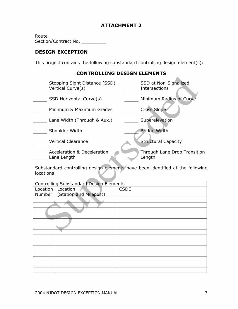
ATTACHMENT 2 Route _________ Section/Contract No. _________
DESIGN EXCEPTION This project contains the following substandard controlling design element(s):
CONTROLLING DESIGN ELEMENTS
Stopping Sight Distance (SSD) Vertical Curve(s)
SSD at Non-Signalized Intersections
SSD Horizontal Curve(s) Minimum Radius of Curve
Minimum & Maximum Grades Cross Slope
Lane Width (Through & Aux.) Superelevation
Shoulder Width Bridge Width
Vertical Clearance Structural Capacity
Acceleration & Deceleration Lane Length
Through Lane Drop Transition Length
Substandard controlling design elements have been identified at the following
locations:
Controlling Substandard Design Elements
Location
Number
Location
(Station and Milepost)
CSDE
2004 NJDOT DESIGN EXCEPTION MANUAL 8
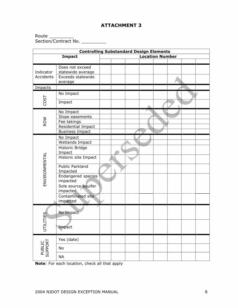
ATTACHMENT 3 Route _________ Section/Contract No. _________
Controlling Substandard Design Elements
Impact Location Number
Indicator
Accidents
Does not exceed
statewide average
Exceeds statewide
average
Impacts
CO
ST No Impact
Impact
RO
W
No Impact
Slope easements
Fee takings
Residential Impact
Business Impact
EN
VIR
ON
MEN
TAL
No Impact
Wetlands Impact
Historic Bridge
Impact
Historic site Impact
Public Parkland
Impacted
Endangered species
impacted
Sole source aquifer
impacted
Contaminated site
impacted
UTIL
ITIE
S
No Impact
Impact
PU
BLIC
SU
PPO
RT
Yes (date)
No
NA
Note: For each location, check all that apply
2004 NJDOT DESIGN EXCEPTION MANUAL 9
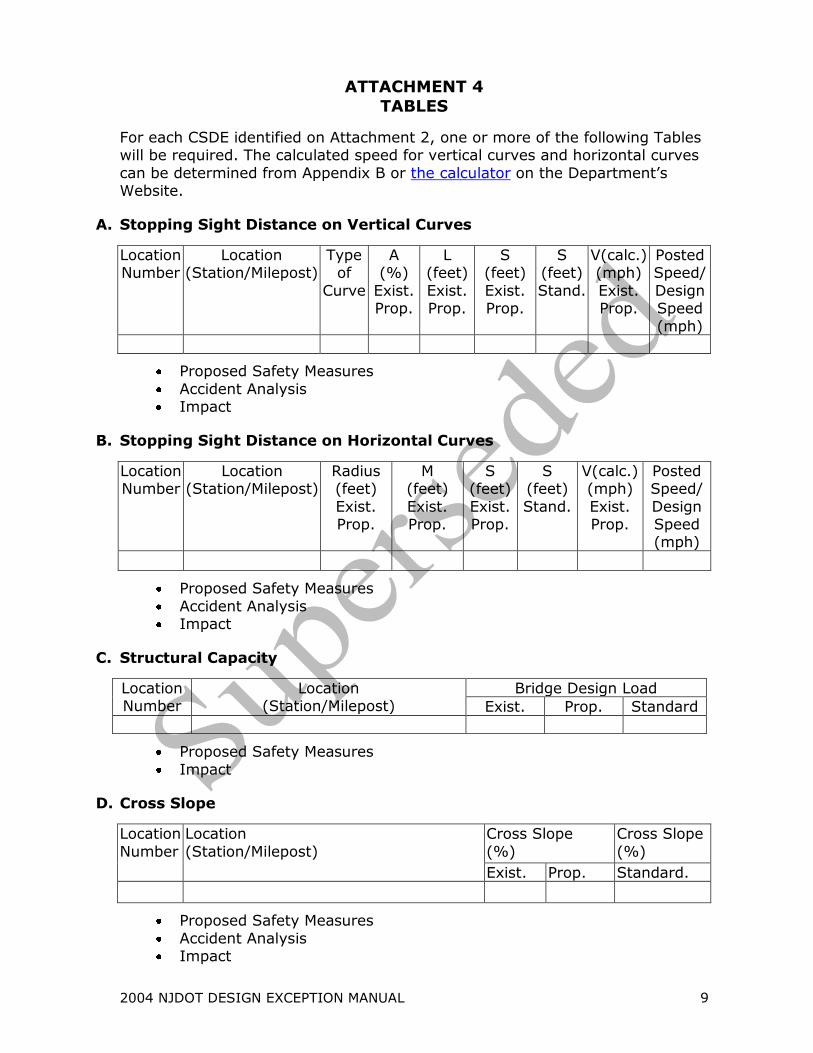
ATTACHMENT 4
TABLES
For each CSDE identified on Attachment 2, one or more of the following Tables will be required. The calculated speed for vertical curves and horizontal curves
can be determined from Appendix B or the calculator on the Department’s Website.
A. Stopping Sight Distance on Vertical Curves
Location Number
Location (Station/Milepost)
Type of
Curve
A (%)
Exist. Prop.
L (feet)
Exist. Prop.
S (feet)
Exist. Prop.
S (feet)
Stand.
V(calc.) (mph)
Exist. Prop.
Posted Speed/
Design Speed
(mph)
Proposed Safety Measures
Accident Analysis Impact
B. Stopping Sight Distance on Horizontal Curves
Location Number
Location (Station/Milepost)
Radius (feet)
Exist. Prop.
M (feet)
Exist. Prop.
S (feet)
Exist. Prop.
S (feet)
Stand.
V(calc.) (mph)
Exist. Prop.
Posted Speed/
Design Speed (mph)
Proposed Safety Measures
Accident Analysis Impact
C. Structural Capacity
Location Number
Location (Station/Milepost)
Bridge Design Load
Exist. Prop. Standard
Proposed Safety Measures
Impact
D. Cross Slope
Location
Number
Location
(Station/Milepost)
Cross Slope
(%)
Cross Slope
(%)
Exist. Prop. Standard.
Proposed Safety Measures
Accident Analysis Impact
2004 NJDOT DESIGN EXCEPTION MANUAL 10
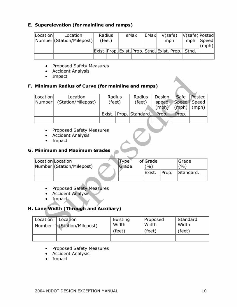
E. Superelevation (for mainline and ramps)
Location Number
Location (Station/Milepost)
Radius (feet)
eMax EMax
V(safe) mph
V(safe) mph
Posted Speed (mph)
Exist. Prop. Exist. Prop. Stnd. Exist. Prop. Stnd.
Proposed Safety Measures Accident Analysis
Impact
F. Minimum Radius of Curve (for mainline and ramps)
Location Number
Location (Station/Milepost)
Radius (feet)
Radius (feet)
Design speed
(mph)
Safe Speed
(mph)
Posted Speed
(mph)
Exist. Prop. Standard. Prop. Prop.
Proposed Safety Measures Accident Analysis
Impact
G. Minimum and Maximum Grades
Location Number
Location (Station/Milepost)
Type of Grade
Grade (%)
Grade (%)
Exist. Prop. Standard.
Proposed Safety Measures Accident Analysis Impact
H. Lane Width (Through and Auxiliary)
Location
Number
Location
(Station/Milepost)
Existing Width
(feet)
Proposed Width
(feet)
Standard Width
(feet)
Proposed Safety Measures
Accident Analysis Impact
2004 NJDOT DESIGN EXCEPTION MANUAL 11
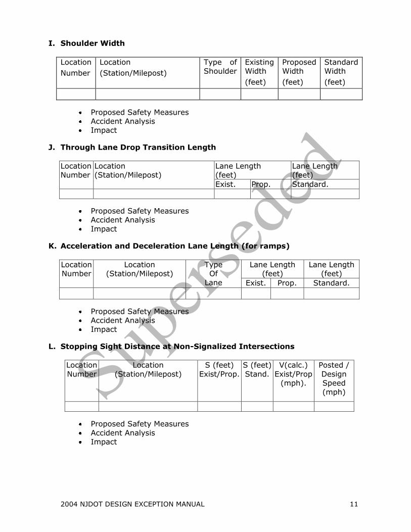
I. Shoulder Width
Location
Number
Location
(Station/Milepost)
Type of Shoulder
Existing Width
(feet)
Proposed Width
(feet)
Standard Width
(feet)
Proposed Safety Measures Accident Analysis Impact
J. Through Lane Drop Transition Length
Location Number
Location (Station/Milepost)
Lane Length (feet)
Lane Length (feet)
Exist. Prop. Standard.
Proposed Safety Measures Accident Analysis
Impact
K. Acceleration and Deceleration Lane Length (for ramps)
Location Number
Location (Station/Milepost)
Type Of
Lane
Lane Length (feet)
Lane Length (feet)
Exist. Prop. Standard.
Proposed Safety Measures Accident Analysis Impact
L. Stopping Sight Distance at Non-Signalized Intersections
Location
Number
Location
(Station/Milepost)
S (feet)
Exist/Prop.
S (feet)
Stand.
V(calc.)
Exist/Prop (mph).
Posted /
Design Speed
(mph)
Proposed Safety Measures
Accident Analysis Impact
2004 NJDOT DESIGN EXCEPTION MANUAL 12
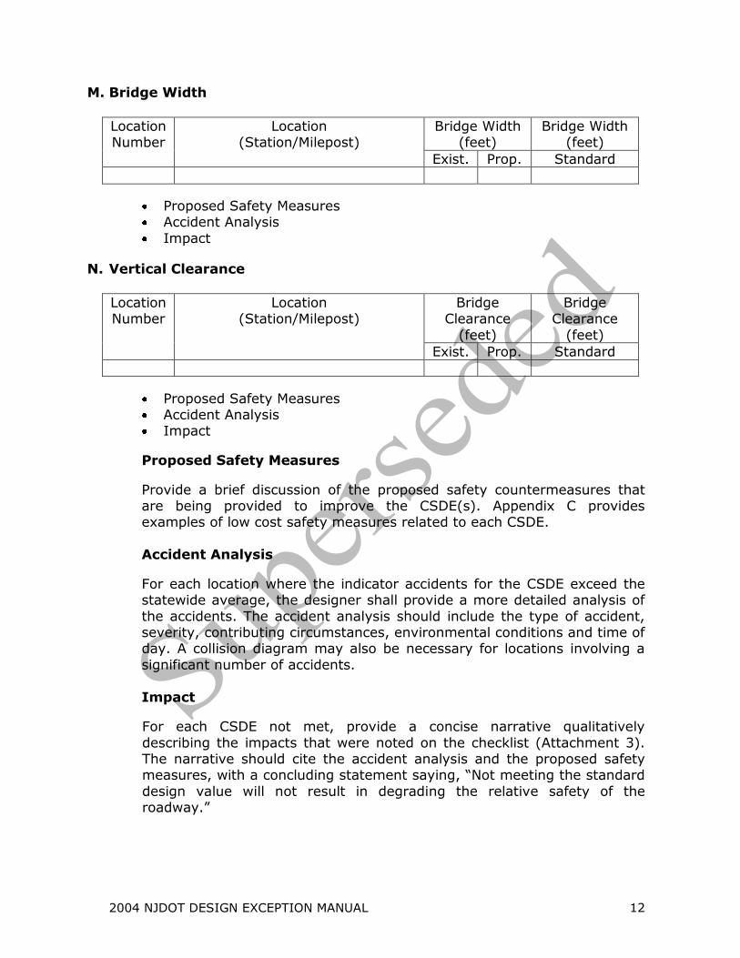
M. Bridge Width
Location Number
Location (Station/Milepost)
Bridge Width (feet)
Bridge Width (feet)
Exist. Prop. Standard
Proposed Safety Measures Accident Analysis
Impact
N. Vertical Clearance
Location Number
Location (Station/Milepost)
Bridge Clearance
(feet)
Bridge Clearance
(feet)
Exist. Prop. Standard
Proposed Safety Measures Accident Analysis Impact
Proposed Safety Measures
Provide a brief discussion of the proposed safety countermeasures that are being provided to improve the CSDE(s). Appendix C provides examples of low cost safety measures related to each CSDE.
Accident Analysis
For each location where the indicator accidents for the CSDE exceed the statewide average, the designer shall provide a more detailed analysis of
the accidents. The accident analysis should include the type of accident, severity, contributing circumstances, environmental conditions and time of day. A collision diagram may also be necessary for locations involving a
significant number of accidents.
Impact
For each CSDE not met, provide a concise narrative qualitatively
describing the impacts that were noted on the checklist (Attachment 3). The narrative should cite the accident analysis and the proposed safety measures, with a concluding statement saying, “Not meeting the standard
design value will not result in degrading the relative safety of the roadway.”

2004 NJDOT Design Exception Manual, Appendix A
APPENDIX A
Reference Tables for Proposed CSDEs
2004 NJDOT Design Exception Manual, Appendix A 1
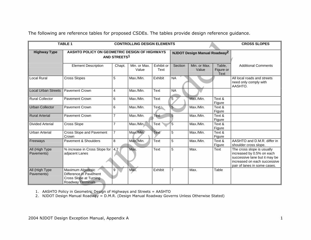
The following are reference tables for proposed CSDEs. The tables provide design reference guidance.
TABLE 1 CONTROLLING DESIGN ELEMENTS CROSS SLOPES
Highway Type AASHTO POLICY ON GEOMETRIC DESIGN OF HIGHWAYS
AND STREETS1
NJDOT Design Manual Roadway2
Element Description Chapt. Min. or Max. Value
Exhibit or Text
Section Min. or Max. Value
Table, Figure or
Text
Additional Comments
Local Rural Cross Slopes 5 Max./Min. Exhibit NA All local roads and streets need only comply with AASHTO.
Local Urban Streets Pavement Crown 4 Max./Min. Text NA
Rural Collector Pavement Crown 6 Max./Min. Text 5 Max./Min. Text & Figure
Urban Collector Pavement Crown 6 Max./Min. Text 5 Max./Min. Text & Figure
Rural Arterial Pavement Crown 7 Max./Min. Text 5 Max./Min. Text & Figure
Divided Arterial Cross Slope 7 Max./Min. Text 5 Max./Min. Text & Figure
Urban Arterial Cross Slope and Pavement Crown
7 Max./Min. Text 5 Max./Min. Text & Figure
Freeways Pavement & Shoulders 8 Max./Min. Text 5 Max./Min. Text & Figure
AASHTO and D.M.R. differ in shoulder cross slope.
All (High Type Pavements)
% increase in Cross Slope for adjacent Lanes
4,7 Max. Text 5 Max. Text The cross slope is usually increased by 0.5% on each successive lane but it may be increased on each successive pair of lanes in some cases.
All (High Type Pavements)
Maximum Algebraic Difference in Pavement Cross Slope at Turning Roadway Terminals
9 Max. Exhibit 7 Max. Table
1. AASHTO Policy in Geometric Design of Highways and Streets = AASHTO 2. NJDOT Design Manual Roadway = D.M.R. (Design Manual Roadway Governs Unless Otherwise Stated)

2004 NJDOT Design Exception Manual, Appendix A 2
TABLE 2 CONTROLLING DESIGN ELEMENTS LANE AND SHOULDER WIDTH
Highway Type AASHTO POLICY ON GEOMETRIC DESIGN OF HIGHWAYS
AND STREETS1
NJDOT Design Manual Roadway2
Element Description Chapt. Min. or Max. Value
Exhibit or Text
Section Min. or Max. Value
Table, Figure or
Text
Additional Comments
Local Rural Lane & Shoulder Width 5 Min. Exhibit AASHTO Governs.
Local Urban Lane Width 5 Max./Min. Text
Parking Lane Width3 5 Min. Text
Rural Collector Lane & Shoulder Width 6 Min. Exhibit 5 Min. Text & Figure
Difference is in graded shoulder when DHV <200.
Urban Collector Roadway Width3 6 Min. Text 5 Min. Text & Figure
Parking Lane3 6 Max./Min. Text AASHTO Governs.
Rural Arterial Lane & Shoulder Width 7 Min. Text & Exhibit
5 Max./Min. Text & Figure
Difference is in usable shoulder when DHV <200.
Auxiliary Lane Width3 3 Max./Min. Text 5 Max./Min. Text
Divided Arterial Lane & Shoulder Width 7 Min. Text 5 Min. Text & Figure
Auxiliary Lane Width3 3 Max./Min. Text 5 Max./Min. Text
Urban Arterial Lane Width 7 Max./Min. Text 5 Max./ Min. Text
Shoulder Width 7 Max./Min. Text 5 Max./Min. Text AASHTO refers to Chapt. 4 for shoulder widths.
Parking Lane3 7 Max./Min. Text AASHTO Governs.
Auxiliary Lane Width3 3 Max./Min. Text 5 Max./Min. Text
Freeway Lane & Shoulder Width 8 Max./Min. Text 5 Max./Min Figure
Auxiliary Lane Width &
Shoulder Treatment3
10 Max./Min. Text 5 Max./Min. Text
1. AASHTO Policy on Geometric Design of Highways and Streets = AASHTO 2. NJDOT Design Manual Roadway = D.M.R. (Design Manual Roadway Governs Unless Otherwise Stated) 3. This is a type of lane and is a controlling design element.
2004 NJDOT Design Exception Manual, Appendix A 3
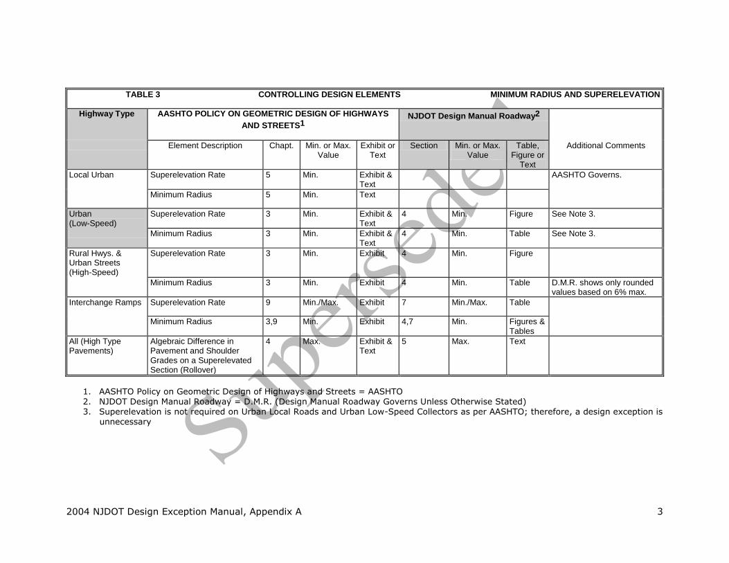
TABLE 3 CONTROLLING DESIGN ELEMENTS MINIMUM RADIUS AND SUPERELEVATION
Highway Type AASHTO POLICY ON GEOMETRIC DESIGN OF HIGHWAYS
AND STREETS1
NJDOT Design Manual Roadway2
Element Description Chapt. Min. or Max. Value
Exhibit or Text
Section Min. or Max. Value
Table, Figure or
Text
Additional Comments
Local Urban Superelevation Rate 5 Min. Exhibit & Text
AASHTO Governs.
Minimum Radius 5 Min. Text
Urban (Low-Speed)
Superelevation Rate 3 Min. Exhibit & Text
4 Min. Figure See Note 3.
Minimum Radius 3 Min. Exhibit & Text
4 Min. Table See Note 3.
Rural Hwys. & Urban Streets (High-Speed)
Superelevation Rate 3 Min. Exhibit 4 Min. Figure
Minimum Radius 3 Min. Exhibit 4 Min. Table D.M.R. shows only rounded values based on 6% max.
Interchange Ramps Superelevation Rate 9 Min./Max. Exhibit 7 Min./Max. Table
Minimum Radius 3,9 Min. Exhibit 4,7 Min. Figures & Tables
All (High Type Pavements)
Algebraic Difference in Pavement and Shoulder Grades on a Superelevated Section (Rollover)
4 Max. Exhibit & Text
5 Max. Text
1. AASHTO Policy on Geometric Design of Highways and Streets = AASHTO 2. NJDOT Design Manual Roadway = D.M.R. (Design Manual Roadway Governs Unless Otherwise Stated) 3. Superelevation is not required on Urban Local Roads and Urban Low-Speed Collectors as per AASHTO; therefore, a design exception is
unnecessary

2004 NJDOT Design Exception Manual, Appendix A 4
TABLE 4 CONTROLLING DESIGN ELEMENTS GRADES
Highway Type AASHTO POLICY ON GEOMETRIC DESIGN OF HIGHWAYS
AND STREETS1
NJDOT Design Manual Roadway2
Element Description Chapt. Min. or Max. Value
Exhibit or Text
Section Min. or Max. Value
Table, Figure or
Text
Additional Comments
Local Rural Maximum Grade 5 Max. Exhibit & Text
NA AASHTO Governs.
Local Urban Max. & Min. Grade 5 Max./Min. Exhibit & Text
NA
Collector Maximum Grade for Urban & Rural
6 Max. Exhibit 4 Max. Table
Rural Arterial Maximum Grade to Design Speed Relationship
7 Max. Exhibit 4 Max. Table
Urban Arterial Maximum Grade 7 Max. Exhibit 4 Max. Table
Freeway Maximum Grade for Urban & Rural
8 Max. Exhibit 4 Max. Table
All Minimum Grade 3 Min. Text 4 Min. Text
1. AASHTO Policy on Geometric Design of Highways and Streets = AASHTO
2. NJDOT Design Manual Roadway = D.M.R. (Design Manual Roadway Governs Unless Otherwise Stated)
2004 NJDOT Design Exception Manual, Appendix A 5
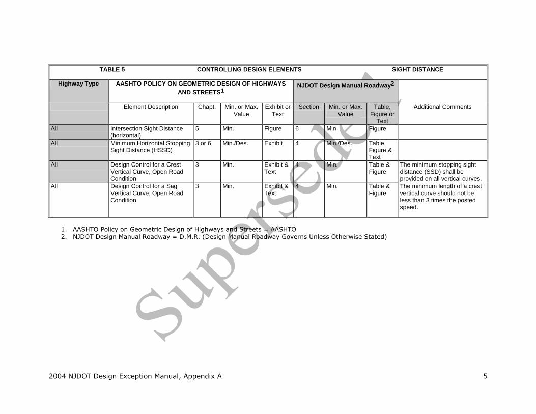
TABLE 5 CONTROLLING DESIGN ELEMENTS SIGHT DISTANCE
Highway Type AASHTO POLICY ON GEOMETRIC DESIGN OF HIGHWAYS
AND STREETS1
NJDOT Design Manual Roadway2
Element Description Chapt. Min. or Max. Value
Exhibit or Text
Section Min. or Max. Value
Table, Figure or
Text
Additional Comments
All Intersection Sight Distance (horizontal)
5 Min. Figure 6 Min Figure
All Minimum Horizontal Stopping Sight Distance (HSSD)
3 or 6 Min./Des. Exhibit 4 Min./Des. Table, Figure & Text
All Design Control for a Crest Vertical Curve, Open Road Condition
3 Min. Exhibit & Text
4 Min. Table & Figure
The minimum stopping sight distance (SSD) shall be provided on all vertical curves.
All Design Control for a Sag Vertical Curve, Open Road Condition
3 Min. Exhibit & Text
4 Min. Table & Figure
The minimum length of a crest vertical curve should not be less than 3 times the posted speed.
1. AASHTO Policy on Geometric Design of Highways and Streets = AASHTO 2. NJDOT Design Manual Roadway = D.M.R. (Design Manual Roadway Governs Unless Otherwise Stated)
2004 NJDOT Design Exception Manual, Appendix A 6
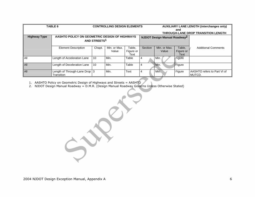
TABLE 6 CONTROLLING DESIGN ELEMENTS AUXILIARY LANE LENGTH (interchanges only) and THROUGH-LANE DROP TRANSITION LENGTH
Highway Type AASHTO POLICY ON GEOMETRIC DESIGN OF HIGHWAYS
AND STREETS1
NJDOT Design Manual Roadway2
Element Description Chapt. Min. or Max. Value
Table, Figure or
Text
Section Min. or Max. Value
Table, Figure or
Text
Additional Comments
All Length of Acceleration Lane 10 Min. Table 4 Min. Figure
All Length of Deceleration Lane 10 Min. Table 4 Min. Figure
All Length of Through-Lane Drop Transition
3 Min. Text 4 Min. Figure AASHTO refers to Part VI of MUTCD.
1. AASHTO Policy on Geometric Design of Highways and Streets = AASHTO 2. NJDOT Design Manual Roadway = D.M.R. (Design Manual Roadway Governs Unless Otherwise Stated)

2004 NJDOT Design Exception Manual, Appendix A 7
TABLE 7 CONTROLLING DESIGN ELEMENTS BRIDGE WIDTH & STRUCTURAL CAPACITY
Highway Type AASHTO POLICY ON GEOMETRIC DESIGN OF HIGHWAYS
AND STREETS1
NJDOT ROADWAY DESIGN MANUAL2
Element Description Chapt. Min. or Max. Value
Table, Figure or
Text
Same As AASHTO
Section Min. or Max. Value
Table, Figure or
Text
Additional Comments
Local Rural & Local Urban
Min. Clear Roadway width & design Loading for a New & Reconstructed Bridge
5 Min. Table & Text
No3 5 Min. Figure See NJDOT Design Manual Bridges & Structures for structural capacity required for each highway type.
Local Rural Min. Struc. Capacity & Min. Roadway Width for a Bridge to remain in place
5 Min. Table No3 5 Min. Figure
Rural & Urban Collector
Min. Struc. Capacity & Min. Roadway Width for Bridge to remain in place
6 Min. Table No3 5 Min. Figure
Min. Struc. Capacity & Min. Roadway Width for New and Reconstructed Bridges
6 Min. Table No3 5 Min. Figure
Rural Arterial Width & Capacity of Structure
74 Min. Text No3 5 Min. Figure
Urban Arterial Width of New Bridge 7 Min. Text Yes3 5 Min. Figure
Freeway Width & Capacity of Structure
84 Min. Text Yes3 5 Min. Figure
1. AASHTO Policy on Geometric Design of Highways and Streets = AASHTO 2. NJDOT Design Manual Roadway = D.M.R. (Design Manual Roadway Governs Unless Otherwise Stated)
3. The minimum bridge design live load for Interstate and NHS highways, and highways where the projected Average Daily Truck Traffic >500 vehicles/day, is MS18+25%. Otherwise, the minimum bridge design live load is MS18+10%. There will be no exceptions to this minimum live load design criteria.
4. AASHTO also refers to Chapt 10.

2004 NJDOT Design Exception Manual, Appendix A 8
TABLE 8 CONTROLLING DESIGN ELEMENTS VERTICAL CLEARANCE
Highway Type AASHTO POLICY ON GEOMETRIC DESIGN OF HIGHWAYS
AND STREETS1
NJDOT Design Manual Roadway2
Element Description Chapt. Min. or Max. Value
Table, Figure or
Text
Section Min. or Max. Value
Table, Figure or
Text
Additional Comments
Local Rural Vertical Clearance 5 Min. Text NA For all highway types refer to the NJDOT Design Manual Bridges & Structures.
Local Urban Vertical Clearance 5 Min. Text NA
Urban & Rural Collector
Vertical Clearance 6 Min. Text NA
Urban & Rural Arterial
Vertical Clearance 7 Min. Text NA
Freeway Vertical Clearance 8 Min. Text NA
1. AASHTO Policy on Geometric Design of Highways and Streets = AASHTO 2. NJDOT Design Manual Roadway = D.M.R. (Design Manual Roadway Governs Unless Otherwise Stated)
2004 NJDOT Design Exception Manual, Appendix B
APPENDIX B
Vertical Curve Conversion Chart From SSD To V (Calc)
& Superelevation Safe Speed Calculation
2004 NJDOT Design Exception Manual, Appendix C 1
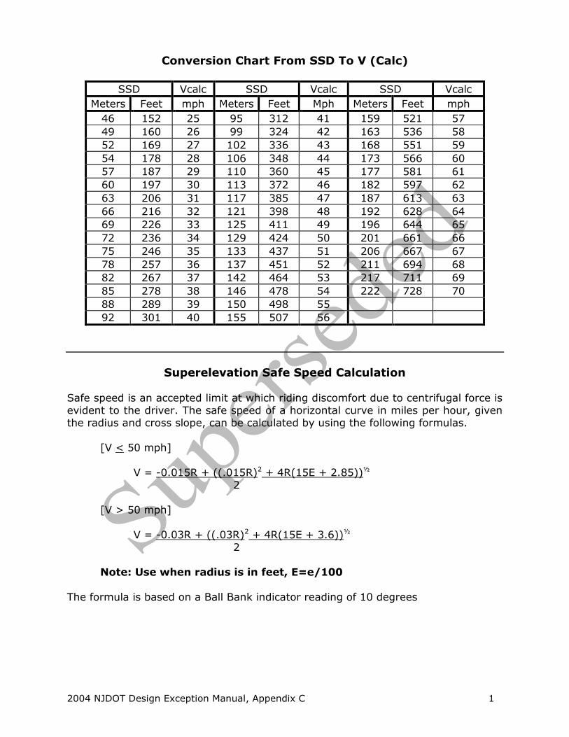
Conversion Chart From SSD To V (Calc)
SSD Vcalc SSD Vcalc SSD Vcalc
Meters Feet mph Meters Feet Mph Meters Feet mph
46 152 25 95 312 41 159 521 57
49 160 26 99 324 42 163 536 58
52 169 27 102 336 43 168 551 59
54 178 28 106 348 44 173 566 60
57 187 29 110 360 45 177 581 61
60 197 30 113 372 46 182 597 62
63 206 31 117 385 47 187 613 63
66 216 32 121 398 48 192 628 64
69 226 33 125 411 49 196 644 65
72 236 34 129 424 50 201 661 66
75 246 35 133 437 51 206 667 67
78 257 36 137 451 52 211 694 68
82 267 37 142 464 53 217 711 69
85 278 38 146 478 54 222 728 70
88 289 39 150 498 55
92 301 40 155 507 56
Superelevation Safe Speed Calculation
Safe speed is an accepted limit at which riding discomfort due to centrifugal force is evident to the driver. The safe speed of a horizontal curve in miles per hour, given
the radius and cross slope, can be calculated by using the following formulas.
[V < 50 mph]
V = -0.015R + ((.015R)2 + 4R(15E + 2.85))½
2 [V > 50 mph]
V = -0.03R + ((.03R)2 + 4R(15E + 3.6))½
2 Note: Use when radius is in feet, E=e/100
The formula is based on a Ball Bank indicator reading of 10 degrees

2004 NJDOT Design Exception Manual, Appendix C
APPENDIX C
Low Cost Safety Measures
2004 NJDOT Design Exception Manual, Appendix C 1
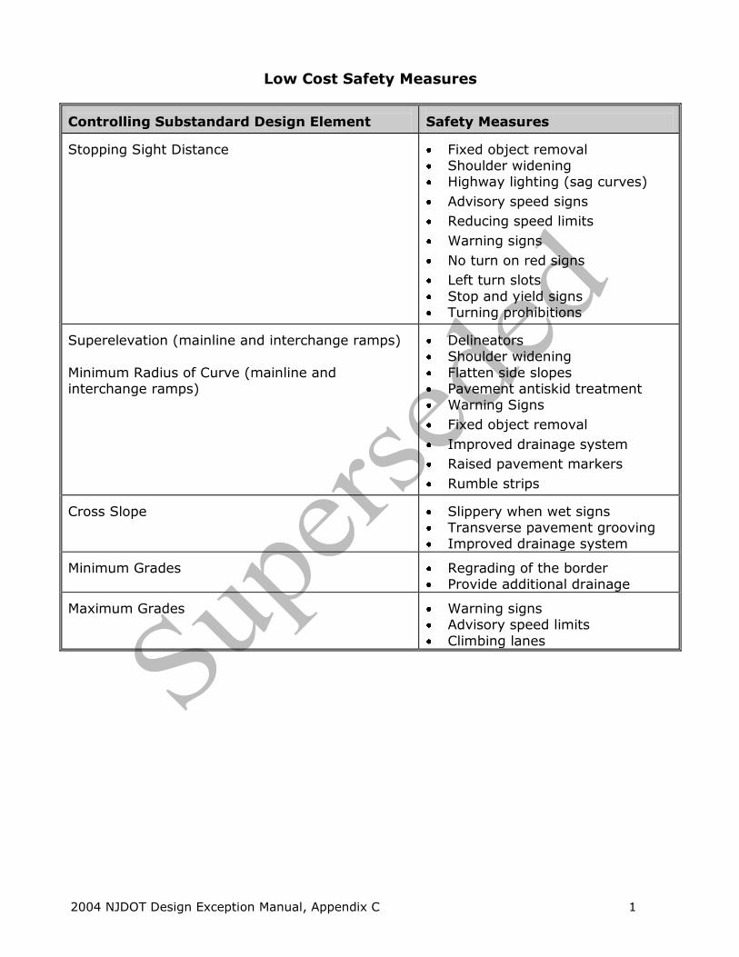
Low Cost Safety Measures
Controlling Substandard Design Element
Safety Measures
Stopping Sight Distance
Fixed object removal Shoulder widening Highway lighting (sag curves)
Advisory speed signs
Reducing speed limits
Warning signs
No turn on red signs
Left turn slots
Stop and yield signs Turning prohibitions
Superelevation (mainline and interchange ramps)
Minimum Radius of Curve (mainline and interchange ramps)
Delineators Shoulder widening
Flatten side slopes Pavement antiskid treatment Warning Signs
Fixed object removal
Improved drainage system
Raised pavement markers
Rumble strips Cross Slope
Slippery when wet signs Transverse pavement grooving Improved drainage system
Minimum Grades
Regrading of the border Provide additional drainage
Maximum Grades
Warning signs Advisory speed limits
Climbing lanes

2004 NJDOT Design Exception Manual, Appendix C 2
Low Cost Safety Measures
Controlling Substandard Design Element
Safety Measures
Lane width (Through and Auxiliary)
Shoulder width
Pavement edge lines Raised pavement markers Delineators
Removing fixed objects Eliminating steep slopes
Signage (narrow lane, narrowed shoulder)
Rumble strip
Beaded / reflective pavement edge, lines
Through-lane Drop Transition Length
Warning signs Advisory speed limits
Acceleration and Deceleration Lane Length (for ramps)
Additional pavement markings and
signing
Delineators Bridge width
Traffic control devices
Approach guide rail Object and pavement markings
Flashers Warning Signs
Vertical Clearance over Roadway
Warning Signs
Structural Capacity
Warning signs
Appendix D contains more detailed tables that show accident types along with probable
causes, studies to be performed to determine probable cause and possible safety measures. Designers can also use this table to conduct a safety analysis in the scoping stages of a project.

2004 NJDOT Design Exception Manual, Appendix D
APPENDIX D
Intersection and Link Accident Tables

2004 NJDOT Design Exception Manual, Appendix D 1
Intersection Accidents
Type of Accident - Left Turn Head On Collision
Probable Causes
1) Restricted sight distance due to presence of left
turning traffic on the opposite approach and improper channelization and geometrics.
2) Too short amber phase. 3) Absence of special left turning phase when
needed. 4) Excessive speed on approaches.
Study to be Performed
1) Review existing intersection channelization. 2) Volume count for thru traffic. 3) Perform volume count for left turning traffic. 4) Review signal phasing. 5) Review intersection clearance times. 6) Study need for special left turn phase. 7) Study capacity of the intersection approaches in
question for possible multi-phase operation. 8) Perform spot speed study.
Possible Safety Measures
1) Provide adequate channelization. 2) Install traffic signal if warranted by MUTCD. 3) Provide left turn slots. 4) Install stop signs if warranted by MUTCD. 5) Increase amber phase. 6) Provide special phase for left turning traffic. 7) Widen road. 8) Prohibit left turns (study possible adverse
effects on other nearby intersections). 9) Reduce speed limit on approaches if justified by
spot speed study. 10) Remove left turn traffic. 11) Provide all red phase.
2004 NJDOT Design Exception Manual, Appendix D 2
Intersection Accidents
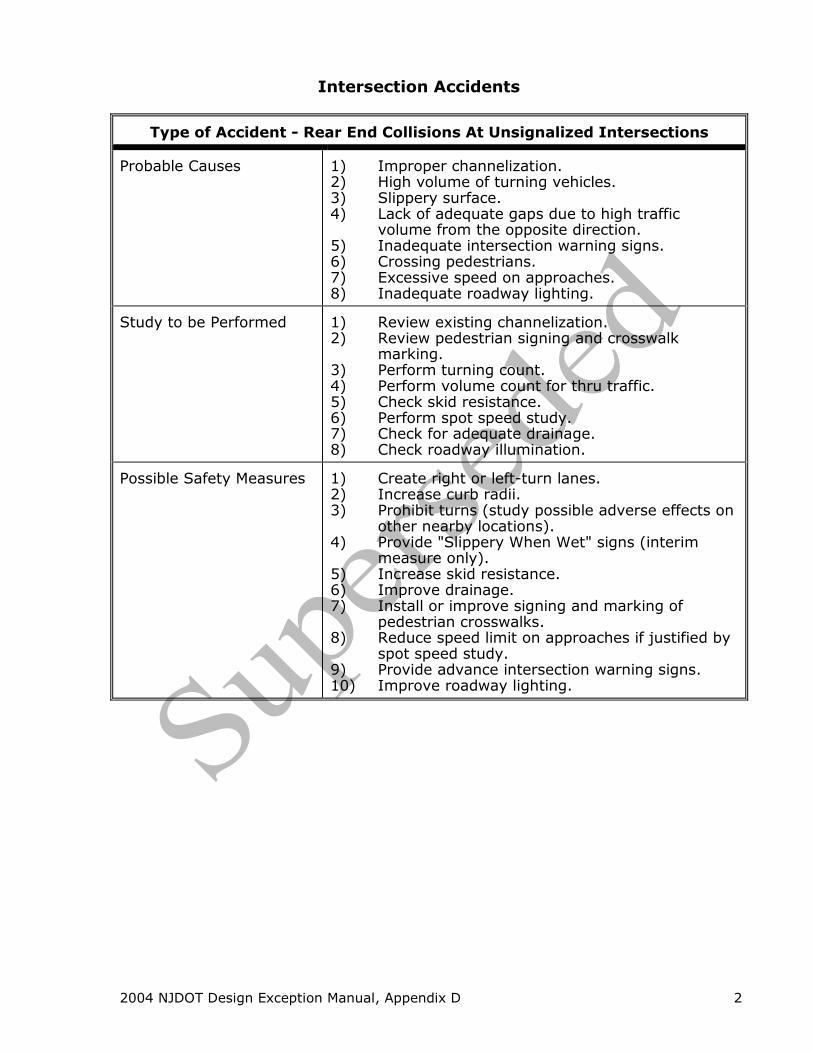
Type of Accident - Rear End Collisions At Unsignalized Intersections
Probable Causes
1) Improper channelization. 2) High volume of turning vehicles. 3) Slippery surface. 4) Lack of adequate gaps due to high traffic
volume from the opposite direction. 5) Inadequate intersection warning signs. 6) Crossing pedestrians. 7) Excessive speed on approaches. 8) Inadequate roadway lighting.
Study to be Performed
1) Review existing channelization. 2) Review pedestrian signing and crosswalk
marking. 3) Perform turning count. 4) Perform volume count for thru traffic. 5) Check skid resistance. 6) Perform spot speed study. 7) Check for adequate drainage. 8) Check roadway illumination.
Possible Safety Measures
1) Create right or left-turn lanes. 2) Increase curb radii. 3) Prohibit turns (study possible adverse effects on
other nearby locations). 4) Provide "Slippery When Wet" signs (interim
measure only). 5) Increase skid resistance. 6) Improve drainage. 7) Install or improve signing and marking of
pedestrian crosswalks. 8) Reduce speed limit on approaches if justified by
spot speed study. 9) Provide advance intersection warning signs. 10) Improve roadway lighting.

2004 NJDOT Design Exception Manual, Appendix D 3
Intersection Accidents
Type of Accident - Rear End Collisions At Signalized Intersections
Probable Causes
1) Improper signal timing. 2) Poor visibility of signal indicator. 3) Crossing pedestrians. 4) High volume of turning vehicles. 5) Slippery surface. 6) Excessive speed on approaches. 7) Inadequate roadway lighting. 8) Inadequate channelization.
Study to be Performed
1) Review existing channelization. 2) Review pedestrian signing and crosswalk
markings. 3) Perform turning count. 4) Perform spot speed study. 5) Check skid resistance. 6) Check for adequate drainage. 7) Check visibility of traffic signals. 8) Check roadway illumination. 9) Review intersection clearance time.
Possible Safety Measures
1) Create right or left-turn lanes. 2) Increase curb radii. 3) Prohibit turns (study possible adverse effects on
other nearby locations). 4) Increase skid resistance. 5) Provide adequate drainage. 6) Provide "Slippery When Wet" signs (interim
measure only). 7) Install advance intersection warning signs. 8) Install or improve signing and marking of
pedestrian crosswalks. 9) Provide pedestrian walk - don't walk indicators. 10) Increase amber phase. 11) Provide special phase for left turning traffic. 12) Provide proper signalized progression. 13) Reduce speed limit on approaches. 14) Install backplates, larger lens, louvers, visors,
etc. on traffic signal to improve contrast and visibility.
15) Relocate signals. 16) Add additional signal heads. 17) Improve roadway lighting.

2004 NJDOT Design Exception Manual, Appendix D 4
Intersection Accidents
Type of Accident - Pedestrian - Vehicle Collision
Probable Causes
1) Inadequate pavement markings. 2) Inadequate channelization. 3) Improper signal phasing. 4) Restricted sight distance. 5) Inadequate pedestrian signals. 6) Inadequate roadway lighting. 7) Inadequate gaps at unsignalized intersection. 8) Excessive vehicle speed.
Study to be Performed
1) Field observation for sight obstructions. 2) Pedestrian volume count. 3) Review channelization. 4) Check roadway illumination. 5) Review pavement markings. 6) Review signal phasing. 7) Perform gap studies. 8) Perform spot speed study.
Possible Safety Measures
1) Install pedestrian crosswalks and signs. 2) Install pedestrian barriers. 3) Prohibit curb parking near crosswalks. 4) Install traffic signal if warranted by MUTCD. 5) Install pedestrian walk - don't walk signals. 6) Increase timing of pedestrian phase. 7) Improve roadway lighting. 8) Prohibit vehicle-turning movements. 9) Remove sight obstructions. 10) Reroute pedestrian paths. 11) Reduce speed limits on approaches if justified by
spot speed studies. 12) Use crossing guards at school crossing areas.

2004 NJDOT Design Exception Manual, Appendix D 5
Intersection Accidents
Type of Accident - Right Angle Collisions At Signalized Intersections
Probable Causes
1) Restricted sight distance. 2) Inadequate roadway lighting. 3) Inadequate advance intersection warning signs. 4) Poor visibility of signal indication. 5) Excessive speed on approaches.
Study to be Performed
1) Volume counts on all approaches. 2) Field observations for sight obstructions. 3) Review signal timing. 4) Check roadway illumination. 5) Perform spot speed study.
Possible Safety Measures
1) Remove obstructions to sight distance. 2) Increase amber phase. 3) Provide all red phase. 4) Retime signals. 5) Prohibit curb parking. 6) Install advance intersection warning signs. 7) Install backplates, larger lens, louvers, visors,
etc., on traffic signal to improve contrast and visibility.
8) Install additional signal heads. 9) Reduce speed limit on approaches if justified by
spot speed studies. 10) Provide proper signalized progression. 11) Improve location of signal heads.

2004 NJDOT Design Exception Manual, Appendix D 6
Intersection Accidents
Type of Accident - Right Angle Collisions At Unsignalized Intersections
Probable Causes
1) Restricted sight distance. 2) Inadequate roadway lighting. 3) Inadequate intersection warning signs. 4) Inadequate traffic control devices. 5) Excessive speed on approaches.
Study to be Performed
1) Volume counts on all approaches. 2) Field observations for sight obstructions. 3) Check roadway illumination. 4) Perform spot speed study. 5) Review signing.
Possible Safety Measures
1) Remove obstructions to sight distance. 2) Prohibit parking near corners. 3) Improve roadway illumination. 4) Install yield or stop signs if MUTCD warrants are
met. 5) Install traffic signal if MUTCD warrants are met. 6) Install advance intersection warning signs. 7) Reduce speed limits on approaches if justified by
spot speed studies.

2004 NJDOT Design Exception Manual, Appendix D 7
Intersection Accidents
Type of Accident - Sideswipe Collisions
Probable Causes
1) Inadequate pavement markings. 2) Inadequate channelization. 3) Inadequate signing. 4) Narrow traffic lanes. 5) Improper street alignment.
Study to be Performed
1) Review pavement markings. 2) Review channelization. 3) Review sign placement. 4) Review lane width. 5) Check alignment.
Possible Safety Measures
1) Provide wider lanes. 2) Install acceleration and deceleration lanes. 3) Place direction and lane change signs to give
proper advance warning. 4) Install or refurbish centerlines, lane lines and
pavement edge lines. 5) Provide turning lanes. 6) Provide proper alignment.

2004 NJDOT Design Exception Manual, Appendix D 8
Link Accidents
Type of Accident - Off-Road Accidents
Probable Causes
1) Inadequate signing and delineators. 2) Inadequate pavement marking. 3) Inadequate roadway lighting. 4) Slippery surface. 5) Improper channelization. 6) Inadequate shoulders. 7) Inadequate pavement maintenance. 8) Inadequate superelevation. 9) Severe curve. 10) Severe grade.
Study to be Performed
1) Review signs and placement. 2) Review pavement marking. 3) Check roadway illumination. 4) Check skid resistance. 5) Review channelization. 6) Check roadside shoulders and road
maintenance. 7) Check superelevation. 8) Check for adequate drainage. 9) Perform spot speed studies.
Possible Safety Measures
1) Install proper centerline, lane lines, and
pavement edge markings. 2) Increase skid resistance. 3) Improve roadway lighting. 4) Install warning signs to give proper advance
warning and advisory speed limit. 5) Install roadside delineators, guide rails and
redirecting barriers. 6) Perform necessary road surface repairs. 7) Improve superelevation at curves. 8) Reduce speed limit if justified by spot speed
studies. 9) Upgrade roadway shoulders. 10) Provide "Slippery When Wet" signs (interim
measure only). 11) Provide adequate drainage. 12) Flatten curve. 13) Provide proper superelevation.

2004 NJDOT Design Exception Manual, Appendix D 9
Link Accidents
Type of Accident - Head-on Collisions
Probable Causes
1) Restricted sight distance. 2) Inadequate pavement markings. 3) Inadequate signing. 4) Narrow lanes. 5) Inadequate shoulders and/or maintenance. 6) Inadequate road maintenance. 7) Excessive vehicle speed. 8) Severe curve. 9) Severe grade.
Study to be Performed
1) Review lane width. 2) Review pavement markings. 3) Review signing. 4) Check road shoulders where present. 5) Check road for proper maintenance. 6) Perform spot speed study. 7) Field check for sight obstructions.
Possible Safety Measures
1) Provide wider lanes. 2) Provide pennant signs. 3) Install no passing zones at points with restricted
sight distances. 4) Install centerlines, lane lines and pavement
edge markings. 5) Improve roadside shoulders. 6) Perform necessary road surface repairs. 7) Reduce speed limits if justified by spot speed
studies. 8) Remove obstructions to sight distances. 9) Flatten curve. 10) Provide proper superelevation.

2004 NJDOT Design Exception Manual, Appendix D 10
Link Accidents
Type of Accident - Pedestrian - Vehicle Collisions
Probable Causes
1) Restricted sight distance. 2) Inadequate roadway lighting. 3) Excessive vehicle speed. 4) Pedestrian walking on roadway. 5) Inadequate signing. 6) Sidewalks too close to roadway. 7) Improper pedestrian crossing.
Study to be Performed
1) Check sight distances. 2) Check roadway illumination. 3) Review existence of sidewalks. 4) Review warning signs and placement. 5) Perform spot speed study.
Possible Safety Measures
1) Improve sight distance. 2) Prohibit curbside parking. 3) Improve roadway lighting. 4) Install sidewalks. 5) Install proper warning signs. 6) Reduce speed limit if justified by spot speed
studies. 7) Install pedestrian barriers. 8) Move sidewalks further from roadway. 9) Enforcement.
2004 NJDOT Design Exception Manual, Appendix D 11
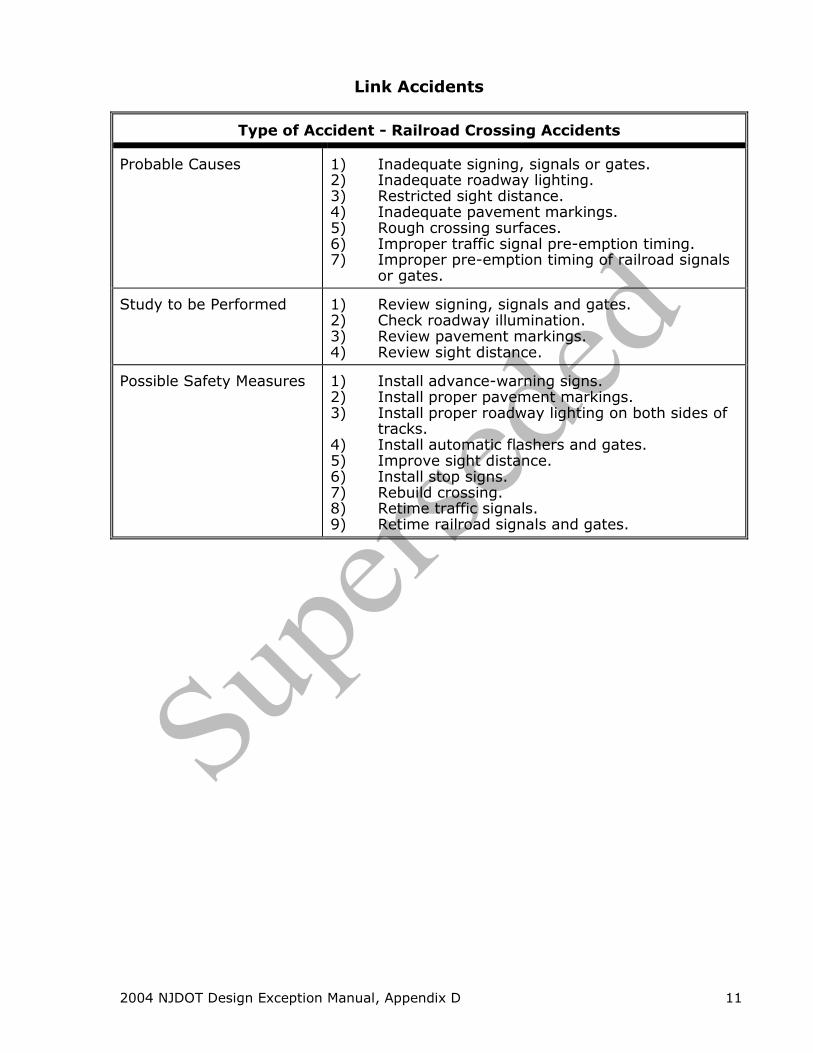
Link Accidents
Type of Accident - Railroad Crossing Accidents
Probable Causes
1) Inadequate signing, signals or gates. 2) Inadequate roadway lighting. 3) Restricted sight distance. 4) Inadequate pavement markings. 5) Rough crossing surfaces. 6) Improper traffic signal pre-emption timing. 7) Improper pre-emption timing of railroad signals
or gates. Study to be Performed
1) Review signing, signals and gates. 2) Check roadway illumination. 3) Review pavement markings. 4) Review sight distance.
Possible Safety Measures
1) Install advance-warning signs. 2) Install proper pavement markings. 3) Install proper roadway lighting on both sides of
tracks. 4) Install automatic flashers and gates. 5) Improve sight distance. 6) Install stop signs. 7) Rebuild crossing. 8) Retime traffic signals. 9) Retime railroad signals and gates.

2004 NJDOT Design Exception Manual, Appendix D 12
Link Accidents
Type of Accident - Parked Car Accidents
Probable Causes
1) Improper pavement markings. 2) Improper parking clearance at driveways. 3) Angle parking. 4) Excessive vehicle speed. 5) Improper parking. 6) Illegal parking.
Study to be Performed
1) Review pavement markings. 2) Review parking clearance from curb. 3) Review angle parking if it exists. 4) Perform spot speed studies. 5) Law observance study.
Possible Safety Measures
1) Convert angle parking to parallel parking. 2) Paint parking stall limits 7 ft. (2.1 m) from curb
face. 3) Post parking restrictions near driveways. 4) Prohibit parking. 5) Create off-street parking. 6) Reduce speed limit if justified by spot speed
studies. 7) Widen lanes. 8) Enforcement.
2004 NJDOT Design Exception Manual, Appendix D 13
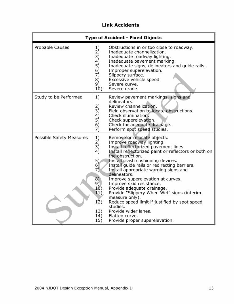
Link Accidents
Type of Accident - Fixed Objects
Probable Causes
1) Obstructions in or too close to roadway. 2) Inadequate channelization. 3) Inadequate roadway lighting. 4) Inadequate pavement marking. 5) Inadequate signs, delineators and guide rails. 6) Improper superelevation. 7) Slippery surface. 8) Excessive vehicle speed. 9) Severe curve. 10) Severe grade.
Study to be Performed
1) Review pavement markings, signs and
delineators. 2) Review channelization. 3) Field observation to locate obstructions. 4) Check illumination. 5) Check superelevation. 6) Check for adequate drainage. 7) Perform spot speed studies.
Possible Safety Measures
1) Remove or relocate objects. 2) Improve roadway lighting. 3) Install reflectorized pavement lines. 4) Install reflectorized paint or reflectors or both on
the obstruction. 5) Install crash cushioning devices. 6) Install guide rails or redirecting barriers. 7) Install appropriate warning signs and
delineators. 8) Improve superelevation at curves. 9) Improve skid resistance. 10) Provide adequate drainage. 11) Provide "Slippery When Wet" signs (interim
measure only). 12) Reduce speed limit if justified by spot speed
studies. 13) Provide wider lanes. 14) Flatten curve. 15) Provide proper superelevation.

2004 NJDOT Design Exception Manual, Appendix D 14
Link Accidents
Type of Accident - Sideswipe Collisions
Probable Causes
1) Inadequate pavement markings. 2) Inadequate channelization. 3) Inadequate signing. 4) Narrow traffic lanes. 5) Improper road maintenance. 6) Inadequate roadside barriers 7) Excessive vehicle speed.
Study to be Performed
1) Review pavement markings. 2) Review channelization. 3) Review sign placement. 4) Review lane width. 5) Check roadside shoulders. 6) Check road surface for proper maintenance. 7) Perform spot speed studies.
Possible Safety Measures
1) Provide wider lanes. 2) Install acceleration and deceleration lanes. 3) Place direction and lane change signs to give
proper advance warning. 4) Install or refurbish centerlines, lane lines and
pavement edge lines. 5) Perform necessary road surface repairs. 6) Improve shoulders. 7) Remove constrictions such as parked vehicles. 8) Install median divider. 9) Reduce speed limit if justified by spot speed
study.

2004 NJDOT Design Exception Manual, Appendix E
APPENDIX E
Sample Design Exceptions
2004 NJDOT Design Exception Manual, Appendix E 1
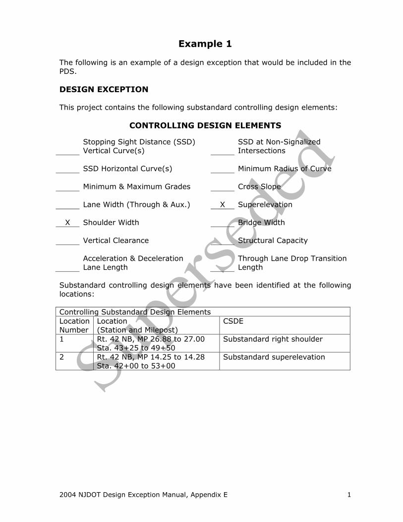
Example 1 The following is an example of a design exception that would be included in the
PDS.
DESIGN EXCEPTION This project contains the following substandard controlling design elements:
CONTROLLING DESIGN ELEMENTS
Stopping Sight Distance (SSD) Vertical Curve(s)
SSD at Non-Signalized Intersections
SSD Horizontal Curve(s) Minimum Radius of Curve
Minimum & Maximum Grades Cross Slope
Lane Width (Through & Aux.) X Superelevation
X Shoulder Width Bridge Width
Vertical Clearance Structural Capacity
Acceleration & Deceleration
Lane Length
Through Lane Drop Transition
Length
Substandard controlling design elements have been identified at the following
locations:
Controlling Substandard Design Elements
Location
Number
Location
(Station and Milepost)
CSDE
1 Rt. 42 NB, MP 26.88 to 27.00
Sta. 43+25 to 49+50
Substandard right shoulder
2 Rt. 42 NB, MP 14.25 to 14.28
Sta. 42+00 to 53+00
Substandard superelevation
2004 NJDOT Design Exception Manual, Appendix E 2
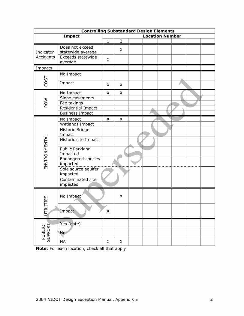
Controlling Substandard Design Elements
Impact Location Number
1 2
Indicator
Accidents
Does not exceed
statewide average X
Exceeds statewide
average X
Impacts
CO
ST No Impact
Impact X X
RO
W
No Impact X X
Slope easements
Fee takings
Residential Impact
Business Impact
EN
VIR
ON
MEN
TAL
No Impact X X
Wetlands Impact
Historic Bridge
Impact
Historic site Impact
Public Parkland
Impacted
Endangered species
impacted
Sole source aquifer
impacted
Contaminated site
impacted
UTIL
ITIE
S
No Impact X
Impact X
PU
BLIC
SU
PPO
RT
Yes (date)
No
NA X X
Note: For each location, check all that apply

2004 NJDOT Design Exception Manual, Appendix E 3
Shoulder Width
Location
Number
Location
(Station/Milepost)
Type of
Shoulder
Existing
Width
(feet)
Proposed
Width
(feet)
Standard
Width
(feet)
1 Rt. 42 NB & SB, MP 26.88 to 27.00
Sta. 43+25 to 49+50
Right Varies
0 to 12
Varies
0 to 12
8
Proposed Safety Measures
The proposed safety measures at Location 1 is resurfacing to improve the pavement skid resistance, installation of 100 mm wide long-life pavement edge lines, raised pavement markers and delineators mounted
on the roadside guide rail.
Accident Analysis
Fixed object accidents at Location Number 1 are over represented. Based upon the data that indicates 27 of the 29 indicator accidents occurred on a wet surface, we believe the wet surface condition is the
major contributing factor to the accidents not the CSDE. A copy of the Bureau of Safety Programs accident analysis is included in the attached
project fact sheet.
Impact
Currently there are no shoulders on Route 42 under the Browning Road
overpass. Providing standard width right shoulders at Location 1 would require the replacement of the Browning Road overpass. The cost to replace the existing overpass is estimated at $2,000,000. There are
currently no other projects for the 5-year program for this location. Not meeting the standard shoulder width at Location 1 will not result in
degrading the relative safety of the roadway.
2004 NJDOT Design Exception Manual, Appendix E 4
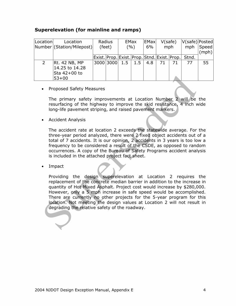
Superelevation (for mainline and ramps)
Location
Number
Location
(Station/Milepost)
Radius
(feet)
EMax
(%)
EMax
6%
V(safe)
mph
V(safe)
mph
Posted
Speed (mph)
Exist. Prop. Exist. Prop. Stnd. Exist. Prop. Stnd.
2 Rt. 42 NB, MP 14.25 to 14.28
Sta 42+00 to 53+00
3000 3000 1.5 1.5 4.8 71 71 77 55
Proposed Safety Measures
The primary safety improvements at Location Number 2 will be the resurfacing of the highway to improve the skid resistance, 4 inch wide
long-life pavement striping, and raised pavement markers.
Accident Analysis
The accident rate at location 2 exceeds the statewide average. For the
three-year period analyzed, there were 2 fixed object accidents out of a total of 7 accidents. It is our opinion, 2 accidents in 3 years is too low a frequency to be considered a result of the CSDE, as opposed to random
occurrences. A copy of the Bureau of Safety Programs accident analysis is included in the attached project fact sheet.
Impact
Providing the design superelevation at Location 2 requires the replacement of the concrete median barrier in addition to the increase in
quantity of Hot Mixed Asphalt. Project cost would increase by $280,000. However, only a 5 mph increase in safe speed would be accomplished. There are currently no other projects for the 5-year program for this
location. Not meeting the design values at Location 2 will not result in degrading the relative safety of the roadway.

2004 NJDOT Design Exception Manual, Appendix E 5
Example 2 The following is an example of a design exception that would be included in the
PDS for a substandard design element on a bridge project.
DESIGN EXCEPTION This project contains the following substandard controlling design element:
CONTROLLING DESIGN ELEMENTS
Stopping Sight Distance (SSD) Vertical Curve(s)
SSD at Non-Signalized Intersections
SSD Horizontal Curve(s) Minimum Radius of Curve
Minimum & Maximum Grades Cross Slope
Lane Width (Through & Aux.) Superelevation
Shoulder Width X Bridge Width
Vertical Clearance Structural Capacity
Acceleration & Deceleration
Lane Length
Through Lane Drop Transition
Length
Substandard controlling design elements have been identified at the following
locations:
Controlling Substandard Design Elements
Location
Number
Location
(Station and Milepost)
CSDE
1 Rt35 NB & SB
MP 51.5 to 52.10 Sta. 150+00 to 181+68
Substandard bridge width
2004 NJDOT Design Exception Manual, Appendix E 6
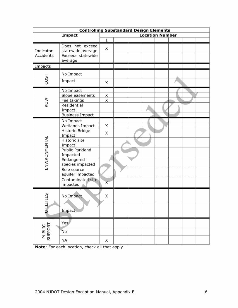
Controlling Substandard Design Elements
Impact Location Number
1
Indicator
Accidents
Does not exceed
statewide average X
Exceeds statewide
average
Impacts
CO
ST No Impact
Impact X
RO
W
No Impact
Slope easements X
Fee takings X
Residential
Impact
Business Impact
EN
VIR
ON
MEN
TAL
No Impact
Wetlands Impact X
Historic Bridge
Impact X
Historic site
Impact
Public Parkland
Impacted
Endangered
species impacted
Sole source
aquifer impacted
Contaminated site
impacted X
UTIL
ITIE
S
No Impact X
Impact
PU
BLIC
SU
PPO
RT
Yes
No
NA X
Note: For each location, check all that apply
2004 NJDOT Design Exception Manual, Appendix E 7
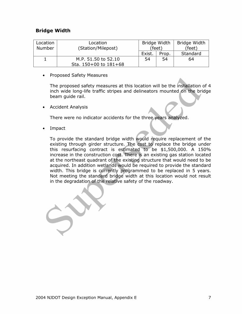
Bridge Width
Location
Number
Location
(Station/Milepost)
Bridge Width
(feet)
Bridge Width
(feet)
Exist. Prop. Standard
1 M.P. 51.50 to 52.10 Sta. 150+00 to 181+68
54 54 64
Proposed Safety Measures
The proposed safety measures at this location will be the installation of 4 inch wide long-life traffic stripes and delineators mounted on the bridge
beam guide rail.
Accident Analysis
There were no indicator accidents for the three years analyzed.
Impact
To provide the standard bridge width would require replacement of the existing through girder structure. The cost to replace the bridge under
this resurfacing contract is estimated to be $1,500,000. A 150% increase in the construction cost. There is an existing gas station located
at the northeast quadrant of the existing structure that would need to be acquired. In addition wetlands would be required to provide the standard width. This bridge is currently programmed to be replaced in 5 years.
Not meeting the standard bridge width at this location would not result in the degradation of the relative safety of the roadway.

2004 NJDOT Design Exception Manual, Appendix E 8
Example 3 The following is an example of a design exception on a project that does not
require a PDS.
NEW JERSEY DEPARTMENT OF TRANSPORTATION
MEMORANDUM
To: Mr. Arthur D. Ziner
Director, Division of Design Services
From: Mr. John Smith Project Manager, Division of Project Management
Date: April 15, 2003
Phone: 609-530-0003 RE: DESIGN EXCEPTION
Route, U.S. 206, Contract Number 0000000 Southampton Township
Burlington County Milepost 14.00 to 14.19
Project Category: NHS Bridge Replacement NJDOT Job Number: 5733313 Federal Project Number: BR-000S(131)
Approval of the design exception is requested to the following controlling
design substandard elements contained in the NJDOT Design Manual Roadway; NJDOT Design Manual Bridges and Structures; AASHTO publication, A Policy on Geometric Design of Highways and Streets 2001 based on the warranting
conditions described herein:
Attached is list by location of the impacts for the CSDE identified. Please refer to the attached Project Fact Sheet for the project description. An
accident analysis is also included.
Based on the warranting conditions presented (the existing conditions, proposed geometry, impacts, accident analysis and safety measures), it is recommended that the design exception be approved.
Approval By:
_____________________________________ _______________
Mr. Arthur D. Ziner Date
Director, Division of Design Services

2004 NJDOT Design Exception Manual, Appendix E 9
Route U.S. 206 Contract No. 00000000
DESIGN EXCEPTION This project contains the following substandard controlling design element:
CONTROLLING DESIGN ELEMENTS
Stopping Sight Distance (SSD) Vertical Curve(s)
SSD at Non-Signalized Intersections X
SSD Horizontal Curve(s) Minimum Radius of Curve
Minimum & Maximum Grades Cross Slope
Lane Width (Through & Aux.) Superelevation
Shoulder Width Bridge Width
Vertical Clearance Structural Capacity
Acceleration & Deceleration
Lane Length Through Lane Drop Transition
Length
Substandard controlling design elements have been identified at the following
locations:
Controlling Substandard Design Elements
Location
Number
Location
(Station and Milepost)
CSDE
1 Rt. U.S 206, MP 14.0
Sta. 13+00 to 16+00 Substandard vertical curve

2004 NJDOT Design Exception Manual, Appendix E 10
Controlling Substandard Design Elements
Impact Location Number
1
Indicator
Accidents
Does not exceed
statewide average X
Exceeds statewide
average
Impacts
CO
ST No Impact
Impact X
RO
W
No Impact
Slope easements X
Fee takings
Residential
Impact X
Business Impact X
EN
VIR
ON
MEN
TAL
No Impact
Wetlands Impact X
Historic Bridge
Impact
Historic site
Impact
Public Parkland
Impacted
Endangered
species impacted
Sole source
aquifer impacted
Contaminated site
impacted
UTIL
ITIE
S
No Impact X
Impact
PU
BLIC
SU
PPO
RT
Yes
No
NA X
Note: For each location, check all that apply

2004 NJDOT Design Exception Manual, Appendix E 11
Route U.S. 206 Contract No. 00000000
Stopping Sight Distance on Vertical Curves
Location
Number
Location
(Milepost/Station)
Type
of Curve
A
(%) Exist.
Prop.
L
(feet) Exist.
Prop.
S
(feet) Exist.
Prop.
S
(feet) Stand.
V(calc.)
(mph) Exist.
Prop.
Posted
Speed/ Design
Speed (mph)
1 M.P 14.08
Sta. 13+00 to 16+00
Crest 4.5/4.5 300/300 389/389 495 47/47 50/55
Proposed Safety Measures
Route U.S. 206 will be resurfaced within the project limits to improve
pavement skid resistance. Shoulders will be provided and the guide rail updated to current standards.
Accident Analysis
There were no indicator accidents for the three years analyzed.
Impacts
To provide the standard length of vertical curve would require raising the
existing road profile. Raising the roadway profile would require extending the project an additional 1400 feet and increase the project construction by $500,000. An increase in the roadway profile would
impact approximately one half acre of wetland and requires slope easements from forty residential properties and one business property.
The additional slope easement required from the business property would eliminate all its parking spaces and require relocation of the access driveway in order to limit the maximum driveway gradient to 8%.
It is estimated that the cost to acquire the business would be approximately $500,000. There are currently no other projects for the 5-
year program for this location. Not meeting the length of vertical will not result in degrading the relative safety of the roadway.
2004 NJDOT Design Exception Manual, Appendix E 12
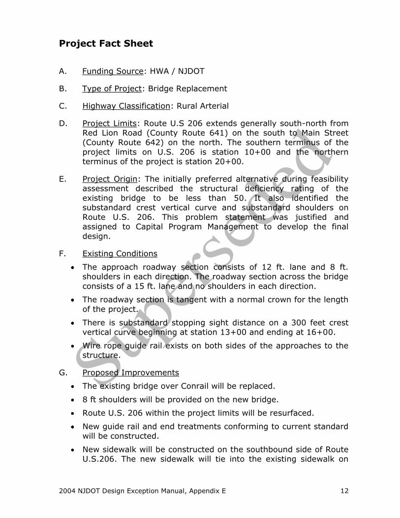
Project Fact Sheet
A. Funding Source: HWA / NJDOT
B. Type of Project: Bridge Replacement
C. Highway Classification: Rural Arterial
D. Project Limits: Route U.S 206 extends generally south-north from Red Lion Road (County Route 641) on the south to Main Street
(County Route 642) on the north. The southern terminus of the
project limits on U.S. 206 is station 10+00 and the northern terminus of the project is station 20+00.
E. Project Origin: The initially preferred alternative during feasibility assessment described the structural deficiency rating of the
existing bridge to be less than 50. It also identified the substandard crest vertical curve and substandard shoulders on
Route U.S. 206. This problem statement was justified and assigned to Capital Program Management to develop the final
design.
F. Existing Conditions
The approach roadway section consists of 12 ft. lane and 8 ft. shoulders in each direction. The roadway section across the bridge
consists of a 15 ft. lane and no shoulders in each direction.
The roadway section is tangent with a normal crown for the length
of the project.
There is substandard stopping sight distance on a 300 feet crest vertical curve beginning at station 13+00 and ending at 16+00.
Wire rope guide rail exists on both sides of the approaches to the structure.
G. Proposed Improvements
The existing bridge over Conrail will be replaced.
8 ft shoulders will be provided on the new bridge.
Route U.S. 206 within the project limits will be resurfaced.
New guide rail and end treatments conforming to current standard will be constructed.
New sidewalk will be constructed on the southbound side of Route U.S.206. The new sidewalk will tie into the existing sidewalk on

2004 NJDOT Design Exception Manual, Appendix E 13
the south side of the bridge at Station 10+00 and extend to the
existing sidewalk at station 17+00 on the north side of the bridge.
H. Roadway Section: The proposed roadway section within the
project limits will consist of a 12 ft. lane and an 8 ft. shoulder in each direct direction. The cross slope in the lane and shoulder will
be 1.5% and 4% respectively.
I. ADT: Existing ADT is 12000 vpd (in 2003). Expected ADT for 2023
is 18000 vpd.
K. Posted Speed: The posted speed limit on Route U.S. 206 is
50mph.
L. Design Speed: The design speed for this project is 55 mph.
M. Approximate Cost of this Project: $1 million
2004 NJDOT Design Exception Manual, Appendix E 14
State of New Jersey
DEPARTMENT OF TRANSPORTATION
1035 Parkway Avenue
PO Box 614
JAMES E. MCGREEVEY Trenton, New Jersey 08625-0614 Jack Lettiere
Governor Commissioner
Joseph Johnson February 14, 2003 Project Designer
Consulting Engineering 111 Somewhere Lane
Trenton, NJ 08610 Re: Design Exception Accident Analysis
Route U.S. 206 Southampton Township, Burlington County
Dear Mr. Johnson:
As requested in your letter of January 2, 2003, accident data was collected and analyzed for the subject location. Accident data used is for years 2000 through
2002. The following is a summary of this data. Substandard Stopping Sight Distance on Vertical Curves - The indicator
accidents for this CSDE are same direction accidents. For the three-year period analyzed, there were no indictor accidents.
If you have any questions, please call Richard Petty of this office at (609) 530-0001.
Very truly yours,
Kris Corrigan Manager
Bureau of Safety Programs


