Design Criteria & Specs. for Pressure Sewers, Force … specifications give the minimum requirements...
35
DESIGN CRITERIA AND SPECIFICATIONS FOR PRESSURE SEWERS, FORCE MAINS, GRINDER PUMPS AND APPURTENANCES TULLAHOMA UTILITIES BOARD AUGUST 2011
Transcript of Design Criteria & Specs. for Pressure Sewers, Force … specifications give the minimum requirements...

DESIGN CRITERIA AND SPECIFICATIONS
FOR
PRESSURE SEWERS, FORCE MAINS,
GRINDER PUMPS AND APPURTENANCES
TULLAHOMA UTILITIES BOARD
AUGUST 2011
2
TABLE OF CONTENTS
Detailed Specifications Section 1 Pressure Sewers and Force Mains Pages 3 - 21 Section 2 Grinder Pumps and Appurtenances Pages 22 - 30 Standard Drawings Standard Installation Details Pages 31 - 35 These specifications give the minimum requirements for installation of pressure sewer lines, force mains and appurtenances in the City of Tullahoma, Tennessee. Any special construction problems or conditions not covered under these Specifications shall be submitted to the City for approval. The standard drawings are a part of these Specifications and all construction shall conform to the details shown on the drawings.
3
SECTION 1
PRESSURE SEWERS AND FORCE MAINS 1. Scope of Work The work to be accomplished under this Section consists of the furnishing of all labor,
materials, equipment, and services necessary for the construction of low pressure force mains (pumped sewer lines) and the force mains between the central pumping stations and gravity interceptor sewers.
The low pressure sewer system to be constructed will incorporate a number of individual
grinder pumps which will pump the sewage generated at the various residential, institutional and commercial establishments through a complete network of low pressure force mains (pumped sewer lines ranging in size from 2-inch to 6-inch). The wastewater will be discharged directly into gravity collector sewers or may be re-pumped by conventional sewage pumps located in central pumping stations through separate force mains to gravity interceptor sewers.
Any contractor, developer, or individual planning to install a pressure sewer system in a new
or unsewered development must submit detailed plans prepared by a registered engineer in compliance with Tullahoma Utilities Board Standard Specifications and Details and all applicable State requirements to the Tullahoma Utilities Board and the State Department of Environment and Conservation for review and approval.
The grinder pump installations and associated appurtenances are covered under Section 2
“Grinder Pumps and Appurtenances”. 2. Location of Force Mains The approximate location of the force mains in relation to the limits of rights-of-way,
pavement, etc., is shown on the Plans but not guaranteed. The location shown was chosen to minimize overall project cost with rock excavation, pavement replacement, crushed stone for traffic bound roadway, customer water services, etc., considered. The final location as constructed may be varied by the contractor with the approval of the Tullahoma Utilities Board provided (1) the proposed location is approved by the Tennessee Department of Transportation, Coffee or Franklin County Highway Department, the City of Tullahoma or other agencies or legal entities having jurisdiction; and (2) the effect lessens the project cost. The final location in any event may be varied by necessity due to construction conditions at the direction of the Tullahoma Utilities Board due to requirement of the Tennessee Department of Transportation, Coffee or Franklin County Highway Department, the City of Tullahoma or other agency or legal entity having jurisdiction.
3. Pipe Fittings for Force Mains
4
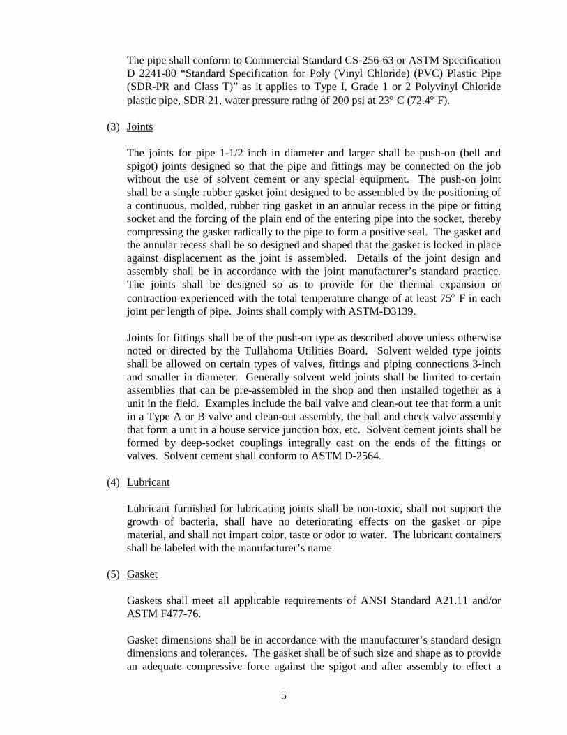
a. General In all areas where ductile iron pipe is not specifically shown, force mains and/or pump
lines may be either Class 50 or 51 ductile iron or 200 psi SDR 21 PVC pipe. b. Ductile Iron Pipe Pipe shall be centrifugally cast, manufactured in accordance with the ANSI
Specification A21.51, of Ductile Cast Iron, Grade 6-42-10, for the required operating pressures as shown on the Plans plus surge allowance of 100 psi, for five feet maximum cover for laying condition “B”. Each pipe shall be hydrostatically tested, before shipment, to a minimum of 500 psi. Minimum nominal metal thickness shall be:
Size 3” 4” 6” 8” 10” Class 50 0.25 0.27 0.29 Class 51 0.25 0.26 Joints shall be push-on joint incorporating a single molded rubber ring gasket, Type II,
per Federal Specifications WW-P-42lb such as “Fastite”, “Tyton” or “Super Bell-Tite” unless otherwise indicated on the Plans or hereinafter in these Specifications. Pipe shall be in nominal 16’, 18’, or 20’ lengths.
Pipe shall be furnished tar coated outside and the manufacturer’s standard “Enameline”
inside to comply with ANSI Specification A21.4. c. Cast or Ductile Iron Fittings All fittings for ductile iron pipe shall be Class 250 mechanical joint cast iron
conforming to ANSI Specifications A21.10 and A21.11 or ductile iron conforming to ANSI Specification A21.51, and shall meet the current requirements for the manufacturer’s standards. Fittings shown on the Plans are intended to convey the general configuration, but the contractor shall furnish all fittings required.
Each fitting shall be certified by the manufacturer to have been tested and to have met
the requirements of the governing standard specifications. All fittings shall be furnished tar coated outside and the manufacturer’s standard
“Enameline” inside to comply with ANSI Specification A21.4. d. Polyvinyl Chloride Pipe
(1) Polyvinyl Chloride pipe for force mains shall be made from Type 1, Grade 1 or 2, Polyvinyl Chloride plastic as defined in ASTM Specification D 1784, “Specifications for Rigid Poly (Vinyl Chloride) Compounds.
(2) Physical Properties
5
The pipe shall conform to Commercial Standard CS-256-63 or ASTM Specification D 2241-80 “Standard Specification for Poly (Vinyl Chloride) (PVC) Plastic Pipe (SDR-PR and Class T)” as it applies to Type I, Grade 1 or 2 Polyvinyl Chloride plastic pipe, SDR 21, water pressure rating of 200 psi at 23° C (72.4° F).
(3) Joints The joints for pipe 1-1/2 inch in diameter and larger shall be push-on (bell and
spigot) joints designed so that the pipe and fittings may be connected on the job without the use of solvent cement or any special equipment. The push-on joint shall be a single rubber gasket joint designed to be assembled by the positioning of a continuous, molded, rubber ring gasket in an annular recess in the pipe or fitting socket and the forcing of the plain end of the entering pipe into the socket, thereby compressing the gasket radically to the pipe to form a positive seal. The gasket and the annular recess shall be so designed and shaped that the gasket is locked in place against displacement as the joint is assembled. Details of the joint design and assembly shall be in accordance with the joint manufacturer’s standard practice. The joints shall be designed so as to provide for the thermal expansion or contraction experienced with the total temperature change of at least 75° F in each joint per length of pipe. Joints shall comply with ASTM-D3139.
Joints for fittings shall be of the push-on type as described above unless otherwise
noted or directed by the Tullahoma Utilities Board. Solvent welded type joints shall be allowed on certain types of valves, fittings and piping connections 3-inch and smaller in diameter. Generally solvent weld joints shall be limited to certain assemblies that can be pre-assembled in the shop and then installed together as a unit in the field. Examples include the ball valve and clean-out tee that form a unit in a Type A or B valve and clean-out assembly, the ball and check valve assembly that form a unit in a house service junction box, etc. Solvent cement joints shall be formed by deep-socket couplings integrally cast on the ends of the fittings or valves. Solvent cement shall conform to ASTM D-2564.
(4) Lubricant Lubricant furnished for lubricating joints shall be non-toxic, shall not support the
growth of bacteria, shall have no deteriorating effects on the gasket or pipe material, and shall not impart color, taste or odor to water. The lubricant containers shall be labeled with the manufacturer’s name.
(5) Gasket Gaskets shall meet all applicable requirements of ANSI Standard A21.11 and/or
ASTM F477-76. Gasket dimensions shall be in accordance with the manufacturer’s standard design
dimensions and tolerances. The gasket shall be of such size and shape as to provide an adequate compressive force against the spigot and after assembly to effect a
6
positive seal under all conditions of joint and gasket tolerances. The trade name or trademark, size, mold number, gasket manufacturer’s mark and year of manufacture shall be molded in the rubber on the back of gaskets.
Gaskets shall be vulcanized natural or vulcanized synthetic rubber. No reclaimed
rubber shall be used. When two hardnesses of rubber are included in a gasket, the soft and hard portions shall be integrally molded and joined in a strong vulcanized bond. They shall be free of porous areas, foreign material and visible defects.
(6) Pipe Lengths The pipe shall be furnished in nominal lengths of 20 feet. The pipe shall be
supported at least every 10 feet of its length during all handling, and special care shall be taken to avoid placing undue stress on the pipe during handling, and any actions that may damage the bell or spigot ends of the pipe shall be avoided.
(7) Fittings Fittings to be installed in conjunction with the force mains between the central
pumping stations and the treatment facilities (6-inch and larger) shall be cast or ductile iron mechanical joints as described in subparagraph 3.c of this Section.
Fittings to be installed in conjunction with the low pressure force main (pumped
sewer lines) shall be of the same material and quality as the pipe and have joints as described in subparagraph 3.d(3) of this Section. The fittings shall be designed to withstand the same pressures required for the pipe. The supplier shall be capable of supplying fittings with combinations of spigot (plain) end and bell.
The pipe supplier shall be capable of supplying special pieces for use in connection
PVC pipe to cast or ductile iron pipe. (8) Approval The pipe and fittings shall be approved by the Tullahoma Utilities Board and adhere
to applicable standards. (9) Marking of Pipe As a minimum, the pipe shall have the following data applied to each piece:
1. Nominal Size 2. Type of Material 3. SDR or Class (color coded) 4. Manufacturer 5. NSF (National Safety Foundation seal of approval) 6. Quality Control Code
7
(10) Testing The following tests shall be performed by the manufacturer of PVC pipe: Long-Term Pressure Test (Min.) 1000 hours at 400 psi Burst Pressure Short Term (Min.) 640 psi Impact (Min.) 60 ft/lbs at 72° F 16 ft/lbs at 0° F Acetone (Min.) 30 minutes no flaking or degradation Crush (Ring Section) 100% crush no cracking Vacuum Test (Min.) 22 in/Hg for 24 hrs. The manufacturer shall report the results of all tests to the Tullahoma Utilities
Board.
4. Excavation for Pipeline Trenches Unless specifically directed otherwise by the Tullahoma Utilities Board or unless required to
uncover or determine the presence of underground obstructions, not more than three hundred (300) feet of trench shall be opened ahead of the pipe laying, and no more than two hundred (200) feet of open ditch shall be left behind the pipe laying. All barricades, lanterns, watchmen, and other such signs and signals as may be necessary to warn the public to the dangers in connection with open trenches, excavations and other obstructions, shall be provided by and at the expense of the contractor. All existing traffic control signals, signs or other facilities shall be kept in place and/or in operation by the contractor. Traffic control signs and construction procedures required by the Tennessee Department of Transportation shall be strictly followed on the portion of the work done on State of Tennessee rights-of-way.
When so required, or when directed by the Tullahoma Utilities Board, only one-half of the
street crossings and road crossings shall be excavated before placing temporary bridges over the side excavating for the convenience of the traveling public. All backfilled ditches shall be maintained in such manner that they will offer no hazard to the passage of traffic. The convenience of the traveling public and the property owners abutting the improvements shall be taken into consideration.
All public or private drives shall be promptly backfilled or bridged at the direction of the Tullahoma Utilities Board. Excavated materials shall be disposed of so as to cause the least interference, and in every case the disposition of excavated materials shall be satisfactory to the Tullahoma Utilities Board.
Trenches shall be opened to a depth so that the top of the pipe shall not be less than two and
one-half (2-1/2) feet below the surface of the ground when laid through wooded areas, fields and other such areas outside the pavement or traveled surface of highways and roadways. The minimum depth of cover shall not be less than three and one-half (3-1/2) feet for pipelines laid within the pavement, traveled surface, or shoulder of any highway and/or
8
roadway. Any line crossing a State Highway shall have a minimum depth of cover of four (4) feet. All depths of cover are measured to the top of the pipe.
Trenches shall be of sufficient width to provide free working space on each side of the pipe
and to permit proper backfilling around the pipe, but unless specifically authorized by the Tullahoma Utilities Board, trenches shall in no case be excavated or permitted to become wider than one foot-six inches (1’ 6”) plus the nominal diameter of the pipe, at the level of the crown of the pipe.
In all areas along State Highways where the pipeline is being laid in the right-of-way of the
road, the Tennessee Department of Transportation requires that excavation during each day be limited to the footage of pipe that can be laid and the trench be backfilled, all in accordance with the applicable provisions of this Section of the Detailed Specifications, and so that no open ditch is left overnight in such areas. The open end of lines in such areas shall be securely plugged when the line is left overnight.
Depth of excavation for footings shall be as shown on the Plans and/or as directed by the
Tullahoma Utilities Board to obtain sufficient bearings. All excavated material not needed for backfilling purposes shall be disposed of in a manner satisfactory to the Tullahoma Utilities Board.
The contractor, at his own expense, shall provide adequate facilities for promptly removing
water from all excavations. The excavation in earth shall be carried to the depth as indicated the Plans and/or directed by
the Tullahoma Utilities Board to permit proper bedding of the pipe. Before laying the pipe, the contractor shall open the trench far enough ahead to reveal
obstructions that may necessitate changing the line or grade of the pipeline. The trench shall be straight and uniform so as to permit laying pipe to lines and grades given
by the Tullahoma Utilities Board The sides of excavations in unstable material shall be supported by substantial sheeting,
bracing and shoring or the sides sloped to the proper angle. Adequate and proper shoring and bracing shall be solely the responsibility of the contractor.
All excavations shall be accomplished in accordance with applicable safety laws and
regulations. 5. Rock Excavation This includes the excavation of all solid rock, such as limestone or sandstone occurring in
mass or ledge formation or such character as to warrant removal by blasting; and it shall also include the removal of boulders equal to or greater than one-half cubic yard in size.
9
In excavating for pipelines in rock, the excavation shall be carried to a depth of six inches below the invert of the pipe.
6. Unauthorized Excavation and Over-Breakage Whenever the excavation is carried beyond or below the lines and grades given by the
Tullahoma Utilities Board, the contractor, at its own expense, shall refill such excavated space with such material and in such a manner as will insure stability of the line involved including the use of crushed stone or Class “C” concrete.
Over-breakage is that portion of any material displaced or loosened beyond the finished
work as planned or authorized by the Tullahoma Utilities Board, including slides. All over-breakage shall be removed by the contractor and disposed of as directed.
7. Crusher-run Stone for Pipe Bedding and Encapsulating Force mains laid in rock are to be encapsulated in a crushed stone envelope and all force
mains shall be bedded with crushed stone. Material for this purpose shall be crusher-run stone meeting the requirements of the Tennessee Department of Transportation, size 67. A minimum of six inches above the pipe, six inches below, and extending to the ditch line on the sides is required where the pipeline is laid in rock. Care should be taken to insure that the bedding material has been worked under the pipe and on each side to provide adequate side support.
If unsuitable material is encountered in the trench bottom, the Tullahoma Utilities Board
may require additional excavation to insure a firm foundation for the pipe. In such cases, the trench bottom shall be brought backup to proper grade with bedding material as provided herein.
8. Pipe Laying The trench shall be excavated to the required depth and width and bell holes and/or jointing
holes shall be dug in advance of pipe laying. The bedding material shall be placed and the bed of each piece of pipe carefully prepared so
that each individual piece of pipe has a uniform bearing. Pipes shall be laid in a straight line and grade without kinks or sags, and shall be laid in a workmanlike manner.
Bell holes and/or jointing holes must be large enough so that the bell or hub will clear the
ground and leave ample room for making joint and inspection of joints. Before each piece of pipe is lowered into the trench, it shall be thoroughly swabbed out to
insure its being clean. Each piece of pipe shall be lowered separately unless special permission is given otherwise by the Tullahoma Utilities Board.
Care shall be taken to prevent injury to the pipe coating, both inside and out. No piece of
pipe or fitting which is known to be defective shall be laid or placed in the lines. If any
10
defective pipe or fittings are discovered after the pipeline is laid, they shall be removed and replaced with a satisfactory pipe or fitting without additional charge. In case a length of pipe is cut to fit a line, it shall be so cut as to leave a smooth end at right angles to the longitudinal axis of the pipe. Pipe shall be cut only by approved methods as listed in the AWWA Specification covering that type of pipe and lining.
All angles or bends in the pipelines, either vertical or horizontal, shall be satisfactorily
braced or anchored against the tendency of movement with a joint harness, concrete or equal anchors to the satisfaction of the Tullahoma Utilities Board.
Open ends of unfinished pipelines shall be securely plugged or closed at the end of each
day’s work or when the line is left temporarily at any other time. 9. Backfilling Pipeline Trenches After the line is bedded and properly laid, crushed stone shall be placed to a level of at least
six inches above the top of the pipe where the pipe is laid in rock. The entire width of the trench shall be filled to this level and compacted adequately to provide uniform side support for the pipeline.
Where the pipe is laid in earth, the backfill from the “haunch” of the pipe to six inches above
the top of the pipe may be the earth material excavated from the trench provided that it is free from lumps, frozen material, etc. Large particles which could damage the pipe shall not be placed in the first 12 inches of backfill above the top of the pipe. It shall be compacted to a minimum of 90% Standard Proctor Density as determined by ASTM D690. A minimum of one field density test by an independent testing laboratory per 1,000 feet of line shall be provided and included in the unit price for the pipe. Additional tests may be ordered by the Tullahoma Utilities Board and any such tests that indicate specified compaction has been achieved shall be paid by the Owner. If the test indicates inadequate compaction, it and re-test to verify adequate compaction will be paid for the contractor.
In filling the remainder of the trench, the backfill material may be shoveled into the trench
without compacting, and heaped over whenever, in the opinion of the Tullahoma Utilities Board, this method of backfilling may be used without inconvenience to the public.
Where street paving or shoulders are to be repaired immediately, the contractor will be
required to backfill the entire trench with crushed stone. Open cut crossings of paved city or county streets will be backfilled with compacted crushed stone.
Backfill of pipelines laid in the rights-of-way of State highway shall be in accordance with the requirement of the Tennessee Department of Transportation. Lines laid in the shoulders, paved ramps, driveways within State rights-of-way shall be backfilled with crushed stone. If paving is to be replaced (except double bituminous), the backfill will stop 11 inches below finish grade to allow for nine inches of binder and two inches of hot mix topping.
Pipe laid in State rights-of-way outside the shoulder may be backfilled with select materials
of the same type as the existing natural material or fill in which the trench is dug. When so
11
required by the Tullahoma Utilities Board, such backfill shall be placed in six-inch layers compacted to 90% Proctor Density.
In areas where the trench is cut into rock or larger broken stone or boulders, and suitable
earth backfill is not available, crushed stone backfill may be required to within six inches of the finished grade. In any trench where the level of excavated rock extends above the level of the top of the pipe, the trench will be backfilled with crushed stone at least six inches above the top of the pipe as a part of the unit price pipe cost.
Before final acceptance, the contractor will be required to level off all trenches where
backfill material has been piled up, or to bring the trench up to level of the surrounding street, roadway, or terrain. The contractor will be required to remove from the streets, roadways, and private property all excess earth or other materials.
10. Inspection of Lines - During Construction The contractor shall notify the Tullahoma Utilities Board when pipe will be received on the
job so that proper arrangements may be made for inspecting the unloading and stringing, as well as inspecting the pipe proper and examining for the manufacturer’s markings for size, class, material code, seal, etc.
Before the contractor backfills any of the lines, they shall be first inspected by the Tullahoma
Utilities Board; and the Tullahoma Utilities Board shall give the contractor permission to proceed with the backfilling. If any joints, pipes, or other workmanship of materials are found to be defective, they shall be removed and replaced by the contractor without any extra compensation.
11. Pipeline Marking with Metalized Tape and Detection Wire All force mains, pumped sewer lines and house service lines from house service junction
box to low pressure force main shall be marked by laying a metalized tape in the ditch above the line to allow location by a metal detecting device. The tape shall be color coded and labeled to identify the type of line and shall be manufactured by Alarmatape, Allen Systems, or equal. Tape shall be within one foot of finish grade and shall be at least six inches wide.
A detection wire shall be installed with all force mains. Wire shall be installed with the pipe
at the trench bottom and stubbed up at each house service connection, valve and clean-out assembly. The wire shall be 14 gauge insulated copper wire, commonly called “bell wire”.
12. Testing of Lines Testing of lines shall comply with the provisions listed below, or similar requirements which
will insure equal or better results.
a. Pipelines of whatever material shall be tested at the pressure as shown in the following table at which pressure the allowable leakage shall not exceed the requirements of Section 13 AWWA specification C600-64 as follows:
12
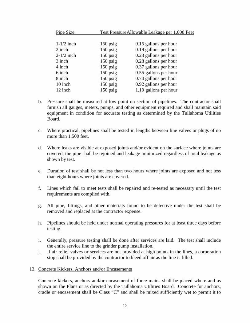
Pipe Size Test Pressure Allowable Leakage per 1,000 Feet 1-1/2 inch 150 psig 0.15 gallons per hour 2 inch 150 psig 0.19 gallons per hour 2-1/2 inch 150 psig 0.23 gallons per hour 3 inch 150 psig 0.28 gallons per hour 4 inch 150 psig 0.37 gallons per hour 6 inch 150 psig 0.55 gallons per hour 8 inch 150 psig 0.74 gallons per hour 10 inch 150 psig 0.92 gallons per hour 12 inch 150 psig 1.10 gallons per hour b. Pressure shall be measured at low point on section of pipelines. The contractor shall
furnish all gauges, meters, pumps, and other equipment required and shall maintain said equipment in condition for accurate testing as determined by the Tullahoma Utilities Board.
c. Where practical, pipelines shall be tested in lengths between line valves or plugs of no
more than 1,500 feet. d. Where leaks are visible at exposed joints and/or evident on the surface where joints are
covered, the pipe shall be rejoined and leakage minimized regardless of total leakage as shown by test.
e. Duration of test shall be not less than two hours where joints are exposed and not less
than eight hours where joints are covered. f. Lines which fail to meet tests shall be repaired and re-tested as necessary until the test
requirements are complied with. g. All pipe, fittings, and other materials found to be defective under the test shall be
removed and replaced at the contractor expense. h. Pipelines should be held under normal operating pressures for at least three days before
testing. i. Generally, pressure testing shall be done after services are laid. The test shall include
the entire service line to the grinder pump installation. j. If air relief valves or services are not provided at high points in the lines, a corporation
stop shall be provided by the contractor to bleed off air as the line is filled.
13. Concrete Kickers, Anchors and/or Encasements Concrete kickers, anchors and/or encasement of force mains shall be placed where and as
shown on the Plans or as directed by the Tullahoma Utilities Board. Concrete for anchors, cradle or encasement shall be Class “C” and shall be mixed sufficiently wet to permit it to
13
flow under the pipe to form a continuous bed. In tamping concrete, care shall be taken not to disturb the grade or line of the pipe or injure the joints. In pouring thrust blocks on plastic pipe, the pipe will first be wrapped with 4 mil visqueen to prevent adherence of the concrete to the pipe.
14. Resilient Seat Gate Valve Resilient seat gave valves shall be as manufactured by Mueller company, or equal, suitable
for utilization with domestic sewage and working pressures of 200 psi. The valve shall consist of a cast iron body, a modified wedge disc, resilient rubber seat ring, non-rising stem bronze stem nut cast integrally with valve disc, and O-ring seals mounted above and below the thrust collar. The resilient seat gate valve shall provide bubble tight shutoff and a full port flow-way. The valve interior shall be fully protected by a two part thermosetting epoxy coating. The modified wedge shall be fully supported with the backside traveling along a machined surface in the valve body. Solid guide lugs on the disc will allow travel within channels cast in the sides of the valve. The resilient rubber seat ring shall be attached to an annular mounting surface on the front side of the disc with stainless steel screws.
All valves shall be furnished with mechanical joint end connections, unless otherwise shown
on the Plans or specified herein. The end connections furnished shall be suitable for connections to the pipe furnished.
All valves shall have the name or monogram of the manufacturer, the year the valve casting
was made, the size of the valve, and the working water pressure cast on the body of the valve. All valves shall be coated with black asphaltum varnish and shall be touched up in the field as required.
All valves shall be provided with a two-inch square operating nut and shall open by turning
to the left (counterclockwise). Valve boxes shall be cast iron, three piece screw type with drop cover marked “Sewer”.
They shall be set vertically and properly adjusted so that the cover shall be in the same plane as the finished surface of the ground or street.
15. Ball Valves Shutoff valves on the pumped sewer lines for sizes three-inch or smaller shall be full ported
PVC, Type 1, Grade 1, ball valves with a tee handle actuator. The valves shall be of the true union type allowing removal of the valve from the line via unions at each end without cutting service line. Ball valves shall have socket end connections with Teflon seats and Viton “O” rings suitable for service with domestic sewage. Port opening through ball shall be same size as pipe. Valves shall be as manufactured by Chemtrol, Hayward Manufacturing Company or equal.
16. Service Connections
14
The Tullahoma Utilities Board will designate the location of the points on the pumped sewer lines or force mains where fittings are to be installed for service connections. The contractor shall keep a detailed record of the locations of these fittings as referenced to surface landmarks to allow easy location of each service connection. Location records shall be submitted to the Resident Inspector as the work progresses.
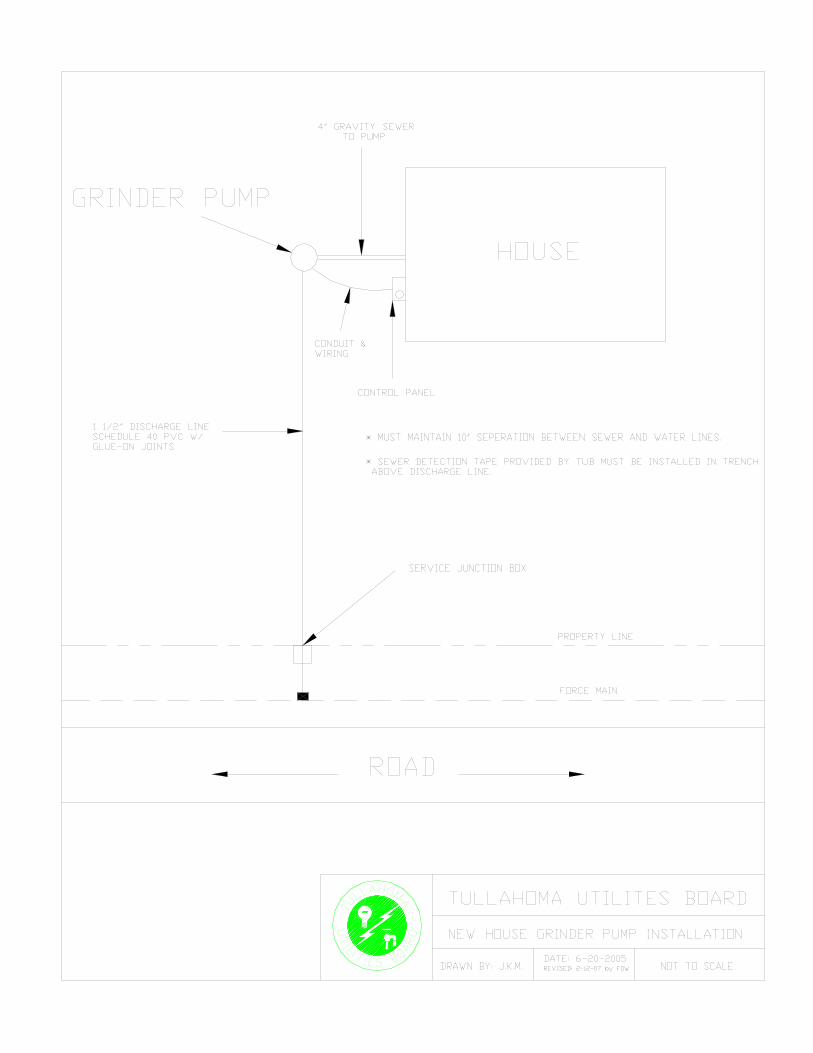
The pressure service lines from each grinder pump installation to the low pressure force
main (pumped sewer line) shall be Class 200, SDR 21, PVC pipe in accordance with the requirements of Paragraph 3.d of this Section of the Specifications. The pressure service line shall be 1-1/2 inch unless otherwise specified on the Plans and shall be laid to follow the ground profile. Service lines installed between grinder pumps and house service junction box will not require crushed stone bedding when laid in earth and shall have a minimum cover of 18 inches. Service lines installed from junction box to pumped sewer line connection point shall be installed in accordance with the requirements of the applicable paragraphs of this Section of the Specifications. The Tullahoma Utilities Board will designate the routing of the service lines in the field.
17. House Service Junction Box A house service junction box with shutoff valve and redundant check valve shall be installed
in the service line from each grinder pump installation near its intersection with the low pressure force main (pumped sewer line) system. The exact location of the service junction box shall be determined in the field by the Tullahoma Utilities Board and shall be in non-traffic areas.
The shutoff valve shall be a full ported PVC, Type 1, Grade 1, ball valve with a tee handle
actuator. The valve shall be of the true union type allowing removal of the valve from the line via unions at each end without cutting the service line. Ball valves shall be 1-1/4 inch in size, with Teflon Seats, socket end connections and Viton “O” rings suitable for service with domestic sewage. Port opening through ball shall be same size as pipe. Valves shall be as manufactured by Chemtrol, Hayward Manufacturing Company, or equal.
The redundant check valve shall be 1-1/4 inch of the gravity operated, flapper-type. The
check valve will provide full-ported passageway when open and shall introduce a friction loss of less than six inches of water at maximum rated flow. Working parts will be made of a 300 series stainless steel and fabric reinforced synthetic elastomer to ensure corrosion resistance, dimensional stability and fatigue strength. A non-metallic hinge shall be an integral part of the flapper assembly providing maximum degrees of freedom for assured seating at a very low back pressure. The valve body shall be a high gloss injected molded part made of PVC, Type I-II, with hub and socket compatible with 1-1/4 inch PVC solvent weld system. Dimensions for hub and socket shall be in accordance with Commercial Standard C5-272-65.
The redundant check valve and ball type shutoff valve shall be housed in a reinforced
concrete box as shown on the drawings. A cover shall be provided which shall have the label “SEWER” stamped into the concrete.
15
18. Valve and/or Cleanout Assemblies The various types of valve and/or clean-out assemblies shall be installed at the general
locations shown on the Plans. The exact location of these assemblies shall be determined in the field by the Tullahoma Utilities Board.
Valves 3-inch or less in diameter associated with the valve and/or clean-out assemblies shall
be PVC ball valves meeting the requirements of Paragraph 15 of this Section of the specifications. Valves 4-inch or larger shall be resilient seat gate valves as described in Paragraph 14 of this Section of the Specifications.
Pits shall be as shown on the Plans complete with frame and cover, connecting piping and all
accessories as shown on the Plans. 19. Combination Air and Vacuum Valves and Pits All force mains shall have air and vacuum release valves installed as they are indicated on
the plans or as directed by the Tullahoma Utilities Board. The body of these valves shall be conical shaped to maintain maximum air gap with the spring loaded float and seal plug connection combining to ensure no contact between the sewage and the seal. The valve shall have a double float design with the upper float being enclosed in the upper section of the valve and shall be made of polypropylene. The lower float shall be in the main body of the valve and shall be constructed of stainless steel. The body shall be constructed of nonferrous materials and shall have a conical shaped lower body to automatically drain sewage back into the system. All internal metal parts are to be made from corrosion resistant stainless steel, with all operating parts in the upper section to be non-metallic plastic materials. The hinge for operation for the opening and closing of the seal on the orifice shall be made of EPDM rubber. The rolling resilient seal shall provide smooth positive opening, closing, and leak free sealing over the fluctuation of pressure differentials. The working pressure shall be 150 psi and test to 225 psi. All hardware shall be of stainless steel bolts and nuts with plastic washer under the bolt and the nut. The connection on all pipelines shall be the following sizing with an isolation valve of the same size:
8 inch and smaller - 2 inch threaded 10 inch through 16 inch - 3 inch threaded All air and vacuum combination release valves shall be model ARI D-025 or approved
equal. All valves shall be installed in accordance with manufacturer recommendations and shall have an isolation valve connection for control. All valves shall have ISO 9002 certification and be warranted for a period of no less than five years.
Automatic sewage type air and vacuum valves and pits shall be installed on the force main at
specific high point locations as shown on the Plans or as directed by the Tullahoma Utilities Board. The exact location of the combination air and vacuum valves assembly shall be determined in the field by the Tullahoma Utilities Board.
16
Pits shall be pre-cast or built in place as shown on the Plans, complete with frame and cover, cutoffs, blowoffs, and all accessories as shown on the Plans or as otherwise required for a complete installation.
20. Replacing Streets and Roadways
a. General The contractor shall replace all streets, alleys and roadways which may be removed,
disturbed or damaged in connection with his operation under the contract. The contractor shall reconstruct same to the original lines and grades and in such manner as to leave all such surfaces in fully as good or better condition than that which existed prior to his operations. The re-use of materials removed in making excavations will be permitted in the manner described, provided said materials are in good condition and acceptable to the Tullahoma Utilities Board.
All City or County Streets and State Highway crossings shall be backfilled with
compacted crushed stone. Gravel, crushed limestone, bituminous materials, or other materials used in the re-
surfacing of streets shall meet the current requirements of the Standard Specifications of the Tennessee Department of Transportation.
b. Removal of Pavement Where pipelines cross or run within paved surfaces of roadways or driveways, extreme
care shall be taken to minimize damage to the pavement. Insofar as possible, paving will be sawed or machine cut to neat, even lines before excavation is started. Trenches within paved surfaces shall be kept to the smallest width possible consistent with safety requirements. Where necessary, trench jacks, temporary sheeting or other methods shall be employed to minimize the width of paving cuts and to maintain adequate safety measures.
In addition, the contractor shall make every effort to avoid incidental damage to
pavement outside the immediate ditch line by using, insofar as is practical, rubber tired equipment, pads for backhoe leveling jacks, and other such measures that would minimize damage.
c. Traffic-Bound Base Course Replacement of streets after trenching shall be handled in the following manner: After the backfill has been compacted to within about three inches of finished grade in
accordance with Paragraph 9 of this Section, the contractor shall place approximately four inches of crushed stone as a traffic-bound base course, at the proper elevation to allow settlement, but not in such a way as to prevent traffic from using it. Crushed
17
stone shall be in accordance with current requirements of the Tennessee Department of Transportation.
The contractor shall maintain the traffic-bound base course by adding crushed stone, as
specified hereinbefore, in a safe and passable condition for a period of 60 days, or until such time as, in the opinion of the Tullahoma Utilities Board, sufficient settlement has taken place and trenches are ready for final re-surfacing. Final depth of base is anticipated to be approximately six inches.
d. Subgrade for Final Re-surfacing The traffic-bound course described above shall comprise the base course for all types of
re-surfacing. When, in the opinion of the Tullahoma Utilities Board, the trench has reached a
condition of settlement satisfactory for final re-surfacing, the contractor shall first strip the base course or backfill with crushed stone (size as specified above) to obtain the proper subgrade elevation. The subgrade shall then be rolled with an approved type roller, or tamped until thoroughly compact and six inches thick.
Any depressions shall be filled with crushed stone or gravel (as specified above) and the
process of rolling or tamping continued until the subgrade has a smooth and uniform surface.
e. Portland Cement Concrete Subslab Where Portland cement concrete pavement subslab is required under bituminous
pavement replacement, it shall conform to the existing pavement and/or the Plans (not less than six-inch thickness). This shall be accomplished with Class “A” concrete. The subgrade shall be prepared as specified above.
f. Bituminous Sand-Gravel Binder Where bituminous sand-gravel binder is required as a base under bituminous pavement
replacement with State Highway rights-of-way, it shall conform to the current standards of the Tennessee Department of Transportation. The thickness of the binder course shall not be less than nine inches. The subgrade shall be prepared as specified above.
g. Asphaltic Concrete Pavement Where asphaltic concrete pavement is to be replaced, the subgrade shall be prepared as
above specified and this subgrade shall comprise the base course upon which the bituminous pavement shall be laid. The existing pavement shall be neatly cut back approximately one foot outside the trench and the new pavement tied into the existing.
The subgrade or base shall be thoroughly cleaned and broomed and a prime coat of
medium tar shall be uniformly applied at a rate of 0.20 to 0.25 gallon per square yard.
18
Where Portland cement concrete subslab is required, the prime shall be applied to the concrete at a rate of 0.05 gallon per square yard. The prime shall be applied by a pressure distributor or other approved pressure spray method.
When the prime coat has become tacky, but not dry and hard, a bituminous surfacing
consisting of asphaltic concrete shall be placed, spread, finished, and compacted in accordance with the current standards of the Tennessee Department of Transportation. Compacted thickness of asphaltic concrete pavement replacement shall generally match the thickness of existing paving.
If the existing paving thickness exceeds six inches, the Tullahoma Utilities Board shall
be notified for a determination of the required thickness for replacement. If paving is less than two inches thick, the replacement paving shall be two inches.
h. Bituminous Surfacing (Surface Treatment) Where bituminous surfacing is to be replaced, as shown on the Plans, or as directed by
the Tullahoma Utilities Board, the traffic-bound base shall comprise the subgrade upon which the bituminous surfacing shall be constructed. After the subgrade or base has been prepared, thoroughly cleaned and broomed, a prime coat of medium tar shall be applied at the rate of 0.30 to 0.35 gallon per square yard.
When the prime coat has become tacky, but not hard, bituminous material (asphalt of
the grade directed by the Tullahoma Utilities Board) shall be applied in two applications at the rate of 0.35 to 0.45 gallon per square yard for each application. The contractor shall apply approximately fifty pounds per square yard to crushed stone between the two applications of bituminous material.
i. Untreated Surface Where the existing surface is untreated crushed stone, the contractor shall replace the
surfacing that is disturbed or removed with crushed stone as above specified, to at least the thickness of the existing surface.
j. Portland Cement Concrete Streets Where Portland Cement concrete pavement must be removed and/or replaced, it shall
conform to the existing pavement and/or the Plans and shall be replaced to a thickness equivalent to the existing pavement, but in no case less than six inches. It shall be accomplished with Class “A” concrete.
21. Remove and/or Replace Concrete Driveways Where portland cement concrete driveways must be removed and/or replaced, they shall be
replaced to a thickness equivalent to the existing pavement, but in no case less than six inches. It shall be accomplished with Class “A” concrete.
19
22. Removing and Replacing Sidewalks and Paved Ditches Whenever sidewalks or paved ditches are removed or disturbed in connection with the
construction work, they shall be replaced to the original lines and grades in fully as good or better condition that which existed prior to the contractor’s operations.
After the sub-base has been brought to a satisfactory grade, a 3-inch layer of cinders or
crushed stone shall be spread over it and thoroughly tamped. Immediately prior to pouring the concrete, the cinders or stone shall be thoroughly wetted, or the concrete shall be poured on a layer of heavy building paper.
The sidewalk shall consist of 4-1/2 inches of Class “A” concrete, struck-off to accurately
placed screeds and worked with a wooden float until the mortar appears on the top. After the surface has been thoroughly floated, it shall be brushed to leave markings of a uniform type similar to the existing walk. All joints and edges shall be finished with an edging tool. The allowable variation shall be 1/8 inch to ten feet transversely and longitudinally.
Other types of sidewalks, such as brick, stone, etc., shall be replaced with material removed
during the progress of the work, in equally as good condition as that found before work started.
23. Removing and Replacing Curb and Gutter Where a concrete curb and gutter is damaged or disturbed during the construction, it shall be
replaced, using Class ”A” concrete, in fully as good or better condition than which existed prior to the contractor’s operation.
24. Seeding All disturbed areas shall be left smooth and thickly sown with a mixture of 20% Blue Grass,
30% Italian Rye Grass, 50% Kentucky Fescue *31 and/or such other grasses as are specified by the Engineer. When the final grading has been completed, the entire area to be seeded shall be fertilized with ammonium nitrate at the rate of five lbs. per 1,000 square feet. The analysis of the commercial fertilizer shall be determined by soil tests. After the fertilizer has been distributed, the contractor shall disc or harrow the ground to thoroughly work the fertilizer into the soil. The seed shall then be sowed in two operations broadcast either by hand or by approved sowing equipment.
The application shall be thirty pounds per acre for each operation. If the Tullahoma Utilities
Board determines to use “hulled” or “unhulled” Bermuda, the application rate shall be seven pounds per acre. After the seed has been distributed, the contractor shall then lightly cover the seed by use of a drag or other approved device. All seed shall be certified not more than three percent weed. The seeded area shall then be covered with straw at the rate of 1-1/4 tons per acre. The straw mulch shall be tacked with asphalt or held in place by a fabric mat to prevent erosion by water or wind.
20
Any necessary re-seeding or repairing shall be accomplished by the contractor prior to final acceptance. If the construction work is brought to completion when, in the opinion of the Tullahoma Utilities Board, the season is not favorable for the seeding of the grounds, then the contractor shall delay this item of work until the proper season for such seeding as directed by the Tullahoma Utilities Board.
All planting and seeding shall be watered thoroughly as soon as completed and shall be
watered twice daily or more often if necessary to provide continuous growth without setback until all growth is thoroughly established. If the contractor does not plan to permanently re-seed within 60 days of backfilling the trench, he shall temporarily re-seed with rye or other appropriate grasses in order to reduce erosion.
25. Highway Crossings (Bored or Jacked) The contractor should familiarize himself with the requirements of the County or State
Highway Department within whose rights-of-way the contractor is working. The City will obtain and pay for any permit it is required to obtain to place the utility within the right-of-way and the contractor, at his expense, shall secure any permit he is required to obtain to work within the right-of-way, if such a permit is required. The contractor shall pay for any insurance to the amount and extent required by the Highway Department involved.
Crossing of County roads will be open cut with permission of the Coffee or Franklin County
Highway Department. Depth of cover shall be four feet as measured from the top of the pipe at the crossing.
Pipeline crossings of U. S. and State of Tennessee highways and where otherwise directed
by the Tullahoma Utilities Board will be made by boring or jacking a smooth wall steel casing pipe under the road bed and inserting the carrier therein. Where boring is required, holes shall be bored under the highway at least five feet below the surface with no disturbance to the surface or as otherwise directed by the Tullahoma Utilities Board. The steel pipe shall be manufactured and tested in accordance with ASTM A139-74, Grade A, with minimum wall thickness and diameter as shown on the Plans, and shall have a minimum yield strength of 35,000 psi. Casing pipe shall be so constructed as to prevent leakage of any substances from the casing throughout its length except at ends. Casing shall be so installed to prevent the formation of a water way under the roadway, with an even bearing throughout its length, and shall slope to one end (except for longitudinal occupancy).
An approved bituminous protective coating shall be applied to the casing pipe to prevent
corrosion both inside and outside. Bored or jacked installations shall have a bored hole diameter essentially the same as the
outside diameter of the pipe plus the thickness of the protective coating. If voids should develop or if the bored hole diameter is greater than the outside of the pipe (including coating) by more than approximately one inch, remedial measures as approved by the Highway Department shall be taken.
21
If approval of the Highway Department is obtained, open cutting of crossings may be permitted. Installations by open-trench methods shall comply with Highway Department specifications. Deletion of the casing pipe for open cut highway crossings or bored and jacked crossings will be permitted provided (1) it meets the approval of the Highway Department; (2) ANSI A21.51 ductile iron pipe with Class 52 minimum wall thickness is used as the carrier and; (3) the overall effect is to reduce the project cost.
26. Erosion and Sediment Control
Construction activities near streams, rivers, and lakes shall meet the regulations of the Department of Environment and Conservation and the City of Tullahoma. Best Management Practices (BMP's) must be designed, installed, and maintained during land disturbing activities.
The contractor shall maintain all areas where excavation and backfilling operations are being
performed or have been performed in order that siltation and bank erosion will be kept to a minimum during construction.
27. Environmental Statement During construction of the project, extreme care shall be exercised to protect graded and
cleared areas. To accomplish this end, temporary grassing, berm ditches and containment dikes may be necessary to minimize the effects of runoff and erosion in the work areas.
28 Cleanup Prior to final acceptance of the work, the contractor will clean up the areas in which it has
performed work, and the area shall be left free of debris, neatly graded, seeded where required and ready for use.
22
SECTION 2
GRINDER PUMPS AND APPURTENANCES
1. Scope This Section of Specifications describes in general terms the grinder pumps and
appurtenances procured by the Tullahoma Utilities Board for installation of any and all low pressure sewer systems installed in the City. Developers, contractors, or individuals will purchase the grinder pumps and appurtenances from the Utilities Board to insure that all low pressure sewer systems installed are uniform, compatible and of the quality standards required by the Board. Installation will be in accordance with Sections 1 and 2 of these Standard Specifications along with the attached Standard Installation Details.
Any contractor, developer, or individual planning to install a pressure sewer system in a new
or unsewered development must submit detailed plans prepared by a registered engineer in compliance with these Tullahoma Utilities Board Standard Specifications and Details and all applicable State requirements to the Tullahoma Utilities Board and the State Department of Environment and Conservation for review and approval.
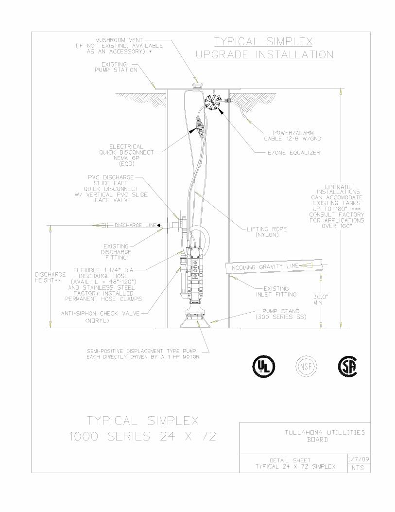
2. Standard Simplex Grinder Pump Units
a. General The standard simplex grinder pump station shall consist of a single grinder type
submersible pump housed in a fiberglass wet well having a steel cover and complete with all appurtenances required for a fully operable pumping system. It shall have an easily removable pump/core assembly containing pump, motor, grinder, all motor controls, check valve, anti-siphon valve, electrical quick disconnect and wiring. Alarm, piping, fittings, valves, and all accessories shall be furnished as a part of the factory fabricated package so that after burying the wet well, the field connection of the gravity inlet line, discharge line and electrical service line to control box will complete the installation of the grinder station.
b. Manufacturer
The grinder pump core unit, complete with all appurtenances, form an integral system,
and as such, shall be supplied by one manufacturer. The contractor shall be responsible for the satisfactory operation of the entire system. The equipment specified shall be a product of a company experienced in the design and manufacture of grinder pumps for specific use in low pressure sewage systems. The company shall submit detailed installation and user instructions for its product, submit evidence of an established service program including complete parts and service manuals, and be responsible for maintaining a continuing inventory of grinder pump replacement parts.
The Manufacturer of the grinder pump station shall be Environment One Corporation (or Proposed Alternate).
23
Attention is directed to the fact that the drawings and overall system design are based on
a particular piece of equipment from a particular manufacturer. These specifications are intended to provide guidelines for standard equipment of a recognized manufacturer who already meets all the requirements of this specification.
c. Pump/Core Unit
The pump shall be integrally designed vertical rotor, motor driven, solids handling
pump of the progressive-cavity type. Each pump installation consists of a grinder pump core mounted on an integral stainless steel stand, electrical quick disconnect (NEMA 6P), pump removal harness, discharge assembly and shut-off valve, anti-siphon valve and check valve assembly, electrical alarm assembly, and all necessary internal wiring and controls.
The pump shall be capable of delivering a design rate of 11 GPM against a rated total
dynamic head of 92 feet (40 PSIG). The pump shall have maximum capacity of 15 GPM against a rated total dynamic head of 0 feet (0 PSIG) and 9 GPM against a rated total dynamic head of 138 feet (60 PSIG). The pump must also be capable of operating at negative total dynamic head without overloading the motor.
The grinder shall be capable of reducing all components in normal domestic and
commercial sewage, including a reasonable amount of “foreign objects”, such as paper, wood, plastic, glass, rubber and the like, to finely divided particles which will pass freely through the passages of the pump and the 1-¼” diameter discharge.
The electric motor shall be a 1 HP, 1725 RPM, 240 Volt 60 Hertz, 1 Phase, capacitor
start, ball bearing, air-cooled induction type with a low starting current not to exceed 30 amps and high starting torque of 8.4 foot pounds. Inherent protection against running overloads or locked rotor conditions for the pump motor shall be provided by the use of an automatic-reset integral thermal overload protector incorporated into the motor.
The pump shall be provided with a mechanical shaft seal to prevent leakage between the
motor and the pump. The seal shall have a stationary ceramic seat and carbon rotating surface with the faces precision lapped and held in position by a stainless steel spring.
d. Wet well Basin The wet well shall consist of a heavy fiberglass basin adequately reinforced for buried
service. The nominal dimensions of the wet well basin shall be 24 inches diameter by a depth of 72 inches. The basin shall be molded of fiberglass reinforced resin of the lay-up and spray technique to assure that the interior surface is smooth and resin rich. The basin shall have a minimum wall thickness of 1/4-inch and a minimum of 25% glass fibers shall be used. A vertical heavy rib or bottom flange shall be provided for anchoring the basin in concrete to prevent floatation.
A removable steel cover coated with high temperature baked epoxy paint shall be provided to allow easy access to pump, piping and level controls. Cover shall be bolted
24
to basin with cap screws and nuts for screws shall be completely embedded in the fiberglass to prevent turning and for corrosion resistance. Tapped-back holes shall be provided in the cover so that cover can be lifted with screws instead of prying on the basin flange.
The standard depth of the wet well basin upon which the base bid of each simplex
grinder pump installation is to be based shall be 72 inches (six feet). Unit prices for other basin depths will also be requested. The prices for each depth shall include all hardware, piping and other appurtenances for a complete installation.
e. Controls
All necessary controls, including motor and level controls, shall be located in the top
housing of the core unit. The top housing will be attached with stainless steel fasteners. Non-fouling wastewater level controls for controlling pump operation shall be
accomplished by monitoring the pressure changes in an integral air column connected to a pressure switch. The level detection device shall have no moving parts in direct contact with the wastewater. High-level sensing will be accomplished in the manner detailed above by a separate air-bell sensor and pressure switch of the same type. Closure of the high-level sensing device will energize an alarm circuit as well as a redundant pump-on circuit. For increased reliability, pump ON/OFF and high-level alarm functions shall not be controlled by the same switch. Float switches of any kind, including float trees, will not be accepted due to the periodic need to maintain (rinsing, cleaning) such devices.
To assure reliable operation of the pressure switches, each core shall be equipped with a
breather assembly, complete with a suitable means to prevent accidental entry of water into the motor compartment. The grinder pump will be furnished with a six conductor, 14 gauge, type SJOW cable, pre-wired and watertight to meet UL requirements with a FACTORY-INSTALLED NEMA 6P EQD half attached to it.
f. Alarm Panel Each grinder pump station shall include a NEMA 4X, UL-listed ALARM PANEL
suitable for wall mounting. The NEMA 4X enclosure shall be manufactured of thermoplastic to assure corrosion resistance. The enclosure shall include a hinged, lockable cover, pad lock, and secured dead front. The enclosure shall not exceed 11.38"W x13.5"H x 5.63"D.
For each core, the panel shall contain one (1) 15-amp, double-pole circuit breaker for
the power circuit and one (1) 15-amp, single-pole circuit breaker for the alarm circuit. The panel shall contain terminal blocks, integral power bus, push to run feature and a complete alarm circuit.
25
The Alarm Panel shall include the following features: audio & visual alarm, push to run switch, and high level (redundant) pump starting control. The alarm sequence is to be as follows:
1. When liquid level in the sewage wet-well rises above the alarm level, visual and
audio alarms will be activated. The contacts on the alarm pressure switch will close. The redundant pump starting system will be energized.
2. The audio alarm may be silenced by means of the externally mounted, push-to-
silence button. 3. Visual alarm remains illuminated until the sewage level in the wet-well drops
below the “off” setting of the alarm pressure switch. The visual alarm lamp shall be inside a red fluted lens at least 2 5/8" in diameter and 1
11/16" in height. Visual alarm shall be mounted to the top of the enclosure in such a manner as to maintain NEMA 4X rating.
The audio alarm shall be a printed circuit board in conjunction with an 86 dB buzzer
with quick mounting terminal strip mounted in the interior of the enclosure. The audio alarm shall be capable of being deactivated by depressing a push-type switch which is encapsulated in a weatherproof silicone boot and mounted on the bottom of the enclosure.
The entire Alarm Panel as manufactured shall be listed by Underwriters Laboratories,
Inc. g. Serviceability The grinder pump core unit shall have two lifting hooks, complete with nylon lift-out
harness, to facilitate easy core removal when necessary. All mechanical and electrical connections must provide easy disconnect capability for core unit removal and installation. A push to run feature will be provided for field trouble shooting. All motor control components shall be mounted on a readily replaceable bracket for ease of field service.
h. Discharge Hose and Disconnect/Valve All discharge fittings and piping shall be constructed of 304 Series stainless steel,
polypropylene, EPDM or PVC. The discharge hose assembly shall include a shut-off valve rated for 200 psi WOG and a quick disconnect feature to simplify installation and pump removal. The bulkhead penetration shall be factory installed and warranted by the manufacturer to be watertight.
26
i. Electrical Quick Disconnect The grinder pump unit shall include a single NEMA 6P electrical quick disconnect
(EQD) for all power and control functions. An integral tube shall allow venting of the control compartment to assure proper operation of the pressure switch level system. The grinder pump will be furnished with a length of 6-conductor, 14-gauge, type SJOW cable, pre-wired and watertight to meet UL requirements.
j. Anti-Siphon Valve The pump discharge shall be equipped with a factory-installed, gravity-operated,
flapper-type integral anti-siphon valve built into the discharge assembly. Moving parts will be made of 300 series stainless steel and fabric-reinforced synthetic elastomer to ensure corrosion resistance, dimensional stability, and fatigue strength. A nonmetallic hinge shall be an integral part of the flapper assembly, providing a maximum degree of freedom to ensure proper operation even at a very low pressure. The valve body shall be injection-molded from a glass-filled thermoplastic resin. Holes or ports in the discharge piping are not acceptable anti-siphon devices, due to their tendency to clog from the solids in the slurry being pumped.
k. Check Valve The pump discharge shall be equipped with a factory installed, gravity operated, flapper-
type integral check valve built into the discharge assembly. The check valve will provide a full-ported passageway when open, and shall introduce a friction loss of less than 6 inches of water at maximum rated flow. Moving parts will be made of a 300 series stainless steel and fabric reinforced synthetic elastomer to ensure corrosion resistance, dimensional stability, and fatigue strength. A nonmetallic hinge shall be an integral part of the flapper assembly providing a maximum degree of freedom to assure seating even at a very low back pressure. The valve body shall be an injection molded part made of glass filled PVC. Ball-type check valves are unacceptable due to their limited sealing capacity in slurry applications.
Each grinder pump installation shall also include one separate check valve of the type
detailed in this section for installation in the 1 1/4" service lateral between the grinder pump station and the sewer main. This check valve shall be located in the house service junction box.
l. OSHA Confined Space All maintenance tasks for the grinder pump station must be possible without entry into
the grinder pump station (as per OSHA 1910.146 Permit-required confined spaces). “Entry means the action by which a person passes through an opening into a permit-required confined space. Entry includes ensuing work activities in that space and is considered to have occurred as soon as any part of the entrant’s body breaks the plane of an opening into the space.”
27
m. Safety The grinder pump shall be free from electrical and fire hazards as required in a
residential environment. As evidence of compliance with this requirement, the completely assembled and wired grinder pump station in its tank shall be listed by Underwriters Laboratories, Inc., to be safe and appropriate for the intended use. UL listing of components of the station or third-party testing to UL standard will not be accepted.
The grinder pump shall meet accepted standards for plumbing equipment for use in or
near residences, shall be free from objectionable noise, odor, or health hazards, and shall have been tested by an independent laboratory to certify its capability to perform as specified in either individual or low pressure sewer system applications. As evidence of compliance with this requirement, the grinder pump shall bear the National Sanitation Foundation seal. Third-party testing to NSF standards will not be accepted.
n. Manufacturer’s Representatives The manufacturer shall include in its bid price the costs of the services of
manufacturer’s factory trained representative to supervise the installation and to supervise the initial start-up and the field acceptance tests of the grinder pump station installations. The manufacturer’s proposal shall include a schedule showing a daily and weekly rate for the factory representative plus travel and per diem charges. The Tullahoma Utilities Board may require this service at various times as pressure systems are installed. Any qualifications, escalation clauses, the lead time notification periods should be stated in the manufacturer’s proposal.
o. Special Tools and Materials The manufacturer shall furnish for each 50 grinder units supplied a complete set of all
special tools and materials needed for the adjustment, operation, and maintenance of the pumps and all equipment associated with the grinder pumping stations.
p. Installation and Operating Instructions Installation of the pump station and related appurtenances shall be done in accordance
with written instructions provided by the manufacturer. The manufacturer shall provide eight copies of a complete and detailed Installation, Operating, and Maintenance Manual. This manual shall cover, in addition to installation and general operating procedures, the operation, maintenance and servicing procedures of the major individual components provided with the pump station. The manual shall also contain a complete breakdown of all components of the pump station and controls with part numbers, pictures, and descriptions to facilitate the ordering of spare parts. The manuals shall be shipped to the Tullahoma Utilities Board.
28
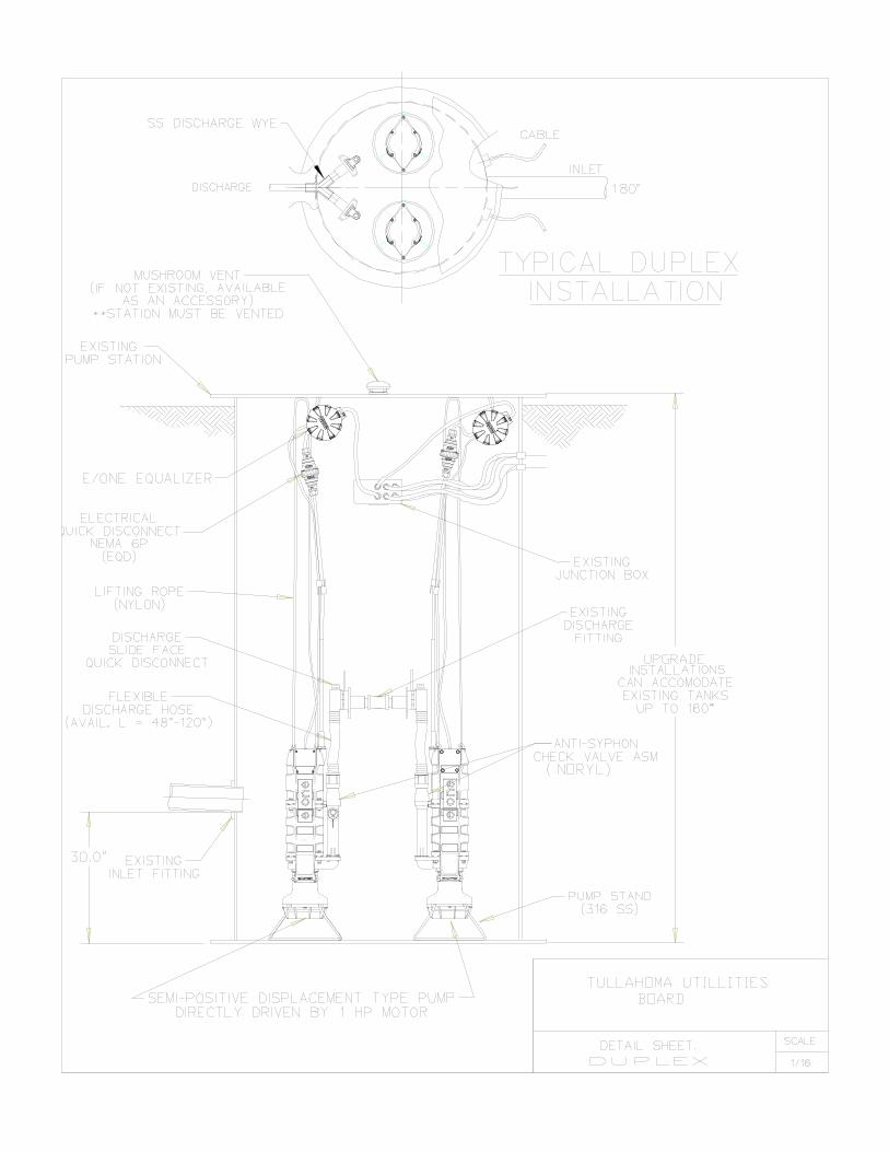
3. Standard Duplex Grinder Pump Station
a. General The standard duplex grinder pump station shall consist of two grinder type submersible
pumps housed in a fiberglass wet well having a steel cover and complete with all appurtenances required for a fully operable pumping system. It shall have easily removable pump assemblies containing pumps, motors, grinders, all motor controls, check valves, anti-siphon valves, electrical quick disconnects and wiring. Alarms, piping, fittings, valves, and all accessories shall be furnished as a part of the factory fabricated package so that after burying the wet well, the field connection of the gravity inlet line(s), discharge line and electrical service line to control box will complete the installation of the grinder station.
The components of the standard duplex grinder pump station are basically identical to the
standard simplex grinder station’s components with the exception that two grinder pumps are required instead of one pump. Therefore, the standard duplex pump station installation shall meet the requirements of Paragraph 2 of this Section of these Specifications with the exception that all additional components required for the operation of two grinder pumps shall be provided.
b. Control/Alarm Panel The grinder pump station shall include a NEMA 4X, UL listed control and alarm
panel(s) suitable for wall or pole mounting by the CONTRACTOR. The NEMA enclosure shall be manufactured of fiberglass to assure corrosion resistance. The enclosure shall include a hinged pad lockable cover.
The panel shall contain one (1) 15-amp single pole circuit breaker for the alarm circuit,
and shall contain one (1) 15-amp double pole circuit breaker per core for the power circuit. The panel shall contain terminal blocks, integral power bus, push to run feature and a complete alarm circuit.
The control/alarm panel(s) shall include the following features: 1. Corrosion-proof fiberglass enclosure 2. NEMA 4X rated enclosure 3. Lockable latch with padlock 4. Circuit breakers 5. Terminal blocks & ground lugs 6. Dry Contacts 7. Lead/Lag indicator lights 8. Alarm indicator lights 9. Run indicator lights
10. Manual Push-to-Run Optional:
29
1. Hour Meters (with larger enclosure) 2. E/One Remote Sentry ready (with power loss capability) The high-level alarm system shall operate as follows: 1. The pumps will go into alarm mode if either pump alarm switch closes. During the
initial alarm mode both pumps will run and the alarm light and horn will be delayed for 3-1/2 minutes. If the station is still in high-level alarm after 3-1/2 minutes the light and horn will be activated.
2. The audio alarm may be silenced by means of the externally mounted push-to-
silence button. 3. Visual alarm remains illuminated until the sewage level in the wet well drops below
the "off" setting of the alarm switch for both pumps. The visual alarm shall be inside a red fluted lens at least 2-5/8" in diameter and 1-11/16 in height. The visual alarm shall be mounted on the top of the enclosure in such a manner to maintain NEMA 4X rating. The entire Control/Alarm Panel, as manufactured, shall be listed by Underwriters Laboratories, Inc.
c. Wet Well Basin
The wet well for a standard duplex station shall consist of a heavy fiberglass basin
having a diameter and depth specified by the engineer or the Tullahoma Utilities Board. Unit prices for other basin depths will also be requested. The prices for each depth shall include all hardware, piping and other appurtenances for a complete installation.
Steel basin covers shall be provided with each basin assembly. Each cover shall have a
hinged access opening properly sized for installation and removal of the pumps assemblies. The access openings shall have a minimum of two hinges and a lock hasp. Covers shall be constructed of non-skid, tread plate steel with a minimum thickness of ¼”. Covers shall be coated with a baked-on epoxy and shall be grass green in color. Covers shall be bolted to the basin with stainless steel cap screws. Zinc plated nuts shall be embedded in the upper flange of the fiberglass basin for corrosion resistance and to prevent turning.
4. Submittals
After receipt of notice to proceed, the manufacturer shall furnish a minimum of six (6) sets of shop drawings detailing the equipment to be furnished including dimensional data and materials of construction. The engineer shall promptly review this data, and return two (2) copies as accepted, or with requested modifications. Upon receipt of accepted shop drawings, the manufacturer shall proceed immediately with fabrication of the equipment.
30
5. Warranty
The grinder pump manufacturer shall provide a part(s) and labor warranty on the complete station and accessories, including, but not limited to, panel and redundant check valve, for a period of twenty-four (24) months after notice of the Tullahoma Utilities Board’s acceptance, but no greater than twenty-seven (27) months after receipt of shipment. Any manufacturing defects found during the warranty period will be reported to the manufacturer by the Tullahoma Utilities Board and will be corrected by the manufacturer at no cost to the Tullahoma Utilities Board.
* * * * * *
32
33
34