DESIGN CRITERIA MANUAL - Surrey design criteria.pdf · ENGINEERING DEPARTMENT JANUARY 2016 DESIGN...
193
ENGINEERING DEPARTMENT JANUARY 2016 DESIGN CRITERIA MANUAL Updated July 11, 2016
Transcript of DESIGN CRITERIA MANUAL - Surrey design criteria.pdf · ENGINEERING DEPARTMENT JANUARY 2016 DESIGN...
ENGINEERING DEPARTMENT
JANUARY 2016
DESIGN CRITERIA MANUALUpdated July 11, 2016

Engineering Department
DESIGN CRITERIA MANUAL
January 2016
City of Surrey TABLE of CONTENTS Engineering Department Page 1-1 Design Criteria Manual January 2016 Section Page
1 INTRODUCTION ............................................................................................................. 1
1.1 Glossary of Terms ............................................................................................................................ 1
1.2 Revisions to this Manual .................................................................................................................. 5
1.3 Interpretation of the Design Criteria ................................................................................................ 5
1.4 Intent and application of these Criteria and Standards ..................................................................... 5
1.5 Measurements / Units ....................................................................................................................... 6
2 GENERAL ......................................................................................................................... 7
2.1 General Items ................................................................................................................................... 7
2.1.1 Existing Infrastructure Information ..................................................................................... 7 2.1.2 Drawing Preparation Standards ........................................................................................... 7 2.1.3 Certification by the Consultant ........................................................................................... 7
2.2 Servicing Requirements Related to Various Zones .......................................................................... 8
2.3 Design Populations ........................................................................................................................ 13
2.3.1 Design Population by Zoning or Land-use Designation ................................................... 13
2.4 Expansion of the City’s Infrastructure ........................................................................................... 15
2.5 Utility Alignments and Services .................................................................................................... 15
2.5.1 Horizontal Separation ........................................................................................................ 17 2.5.2 Vertical Separation ............................................................................................................ 17 2.5.3 Sewers in Common Trench ............................................................................................... 17 2.5.4 Utility Services .................................................................................................................. 18 2.5.5 Cul-de-sac Servicing ......................................................................................................... 18 2.5.6 Utilities Crossing Provincial Highways, Major Roads and Railways ............................... 18 2.5.7 Gas Main Routing ............................................................................................................. 19 2.5.8 Utility Rights-of-Way Width ............................................................................................ 19
2.6 Development Application Process ................................................................................................. 21
City of Surrey TABLE of CONTENTS Engineering Department Page 1-2 Design Criteria Manual January 2016 3 WATER DISTRIBUTION SYSTEM ............................................................................ 23
3.1 Demands and Flows ....................................................................................................................... 23
3.1.1 Per Capita Demands .......................................................................................................... 23 3.1.2 Population Estimates and Equivalents: ............................................................................. 23 3.1.3 Fire Flow Requirements .................................................................................................... 24
3.2 Water System Analysis .................................................................................................................. 25
3.2.1 Existing Water Distribution System .................................................................................. 25 3.2.2 New Water Distribution System ....................................................................................... 25 3.2.3 Hazen-Williams Formula .................................................................................................. 26 3.2.4 The Source Nodes ............................................................................................................. 26 3.2.5 Pressure Zones: ................................................................................................................. 26 3.2.1 Residual Pressure Requirements ....................................................................................... 28 3.2.2 Hydraulic Grade and Maximum Velocities: ..................................................................... 28
3.3 Design of Water System Components ........................................................................................... 29
3.3.1 General .............................................................................................................................. 29 3.3.2 Watermains ....................................................................................................................... 29
3.3.2.1 Size ............................................................................................................. 29 3.3.2.2 Location ..................................................................................................... 29 3.3.2.3 Looping ...................................................................................................... 31 3.3.2.4 Depth .......................................................................................................... 31 3.3.2.5 Grade .......................................................................................................... 31 3.3.2.6 Materials .................................................................................................... 32 3.3.2.7 Corrosion Protection .................................................................................. 32
3.3.3 Gate Valves ....................................................................................................................... 34 3.3.3.1 Size ............................................................................................................. 34 3.3.3.2 Valve Spacing and Configuration .............................................................. 34
3.3.4 Check Valves .................................................................................................................... 34 3.3.5 Air Valves ......................................................................................................................... 34 3.3.6 Hydrants ............................................................................................................................ 35
3.3.6.1 Hydrants – In Road Right-of-Way ............................................................. 35 3.3.6.2 Hydrants – On-Site..................................................................................... 35
3.3.7 Blowdowns and Blowoffs ................................................................................................. 35 3.3.8 Thrust Blocks and Joint Restraints .................................................................................... 36 3.3.9 Service Connections .......................................................................................................... 36 3.3.10 Test Points and Chlorination ............................................................................................. 37 3.3.11 Flexible Expansion Joints .................................................................................................. 37
3.4 Design of Pump Stations and Pressure Reducing Valve Facilities ................................................ 37
3.4.1 General .............................................................................................................................. 37
3.5 Water System Seismic Design Standards ...................................................................................... 38
3.5.1 Area .................................................................................................................................. 38 3.5.2 Materials ............................................................................................................................ 38 3.5.3 Joint Restraint .................................................................................................................... 38 3.5.4 Pipe Wrapping ................................................................................................................... 38 3.5.5 Connections to Structures .................................................................................................. 40 3.5.6 Service Connections .......................................................................................................... 40
City of Surrey TABLE of CONTENTS Engineering Department Page 1-3 Design Criteria Manual January 2016
3.6 Agricultural Water Distribution System ........................................................................................ 40
3.6.1 Domestic Normal Household Water Supply ..................................................................... 40 3.6.1.1 Hydraulic Design ....................................................................................... 40 3.6.1.2 Service Connection .................................................................................... 41
3.6.2 Domestic Non-Household Water Supply .......................................................................... 41 3.6.3 Water System Design ........................................................................................................ 41
4 SANITARY SEWER SYSTEM ..................................................................................... 42
4.1 Sewage Flow Generation ............................................................................................................... 42
4.1.1 Sewage Design Flows ....................................................................................................... 42 4.1.2 Population Estimates and Equivalents: ............................................................................. 42 4.1.3 Peaking Factor ................................................................................................................... 44 4.1.4 Inflow and Infiltration Component ................................................................................... 44
4.2 Sewer System Analysis .................................................................................................................. 44
4.2.1 Submission Requirements ................................................................................................. 44 4.2.2 Existing Sanitary Sewer Systems ...................................................................................... 45 4.2.3 New Sanitary Sewer Systems ............................................................................................ 45 4.2.4 Manning’s Formula ........................................................................................................... 46
4.3 Design of Sanitary Sewer Components .......................................................................................... 46
4.3.1 General .............................................................................................................................. 46 4.3.2 Sanitary Sewers ................................................................................................................. 46
4.3.2.1 Size ............................................................................................................. 46 4.3.2.2 Location ..................................................................................................... 47 4.3.2.3 Depth .......................................................................................................... 47 4.3.2.4 Curvilinear Sewers ..................................................................................... 48 4.3.2.5 Pipe Grades ................................................................................................ 48 4.3.2.6 Velocities ................................................................................................... 48 4.3.2.7 Connections to Metro Vancouver .............................................................. 49
4.3.3 Aerial Pipe Bridges and Inverted Siphons ........................................................................ 49 4.3.4 Manhole Structures ........................................................................................................... 49
4.3.4.1 Location ..................................................................................................... 49 4.3.4.2 Drop Manhole Structures ........................................................................... 50 4.3.4.3 Through Manhole Structures ..................................................................... 50
4.3.5 Service Connections .......................................................................................................... 50 4.3.5.1 Size ............................................................................................................. 50 4.3.5.2 Location, Depth and Grade ........................................................................ 51 4.3.5.3 Tie-in .......................................................................................................... 51
4.3.6 Special Connections .......................................................................................................... 52 4.3.7 Odour Mitigation ............................................................................................................... 52
4.4 Design of Pump Stations and Force Mains .................................................................................... 52
4.5 Low Pressure Sewerage System ..................................................................................................... 52
4.5.1 General .............................................................................................................................. 52 4.5.2 Restrictive Covenant and Sanitary Right-of-Way ............................................................. 53 4.5.3 Codes and Standards ......................................................................................................... 53
City of Surrey TABLE of CONTENTS Engineering Department Page 1-4 Design Criteria Manual January 2016
4.5.4 System Layout ................................................................................................................... 54 4.5.4.1 Preliminary Design .................................................................................... 54 4.5.4.2 Design Development .................................................................................. 54
4.5.5 System Hydraulic Design .................................................................................................. 55 4.5.6 Design Flows and Hydraulics ........................................................................................... 55
4.5.6.1 Single Family Residential Areas ................................................................ 55 4.5.6.2 Multi-Family, Non-Residential and Mixed Areas ..................................... 56 4.5.6.3 Hydraulic Calculations ............................................................................... 56
4.5.7 Pipe .................................................................................................................................. 56 4.5.8 Cleanout Manholes ............................................................................................................ 57 4.5.9 Air Valves ......................................................................................................................... 57 4.5.10 Discharge ........................................................................................................................... 57 4.5.11 Service Connections .......................................................................................................... 57 4.5.12 Pump Unit Requirements .................................................................................................. 57 4.5.13 Pump Chamber Details ...................................................................................................... 58 4.5.14 Piping Details .................................................................................................................... 59 4.5.15 Pump Chamber Ventilation ............................................................................................... 59 4.5.16 Electrical ........................................................................................................................... 60 4.5.17 Pump Chamber Classification ........................................................................................... 60 4.5.18 Controls ............................................................................................................................. 60
4.6 Sanitary Sewer Seismic Design Standards ..................................................................................... 62
4.6.1 Area .................................................................................................................................. 62 4.6.2 Gravity Sewers – Class 1 .................................................................................................. 62
4.6.2.1 Materials .................................................................................................... 62 4.6.2.2 Joint Restraint ............................................................................................ 63 4.6.2.3 Pipe Wrapping ........................................................................................... 63 4.6.2.4 Pipe Flotation Control ................................................................................ 63 4.6.2.5 Manhole Flotation Control ......................................................................... 63 4.6.2.6 Connections to Manholes and Structures ................................................... 64
4.6.3 Gravity Sewers – Class 2 .................................................................................................. 64 4.6.3.1 Material ...................................................................................................... 64 4.6.3.2 Connections to Manholes ........................................................................... 64
4.6.4 Force Main Design ............................................................................................................ 64
5 STORM DRAINAGE SYSTEM .................................................................................... 65
5.1 General ........................................................................................................................................... 65
5.1.1 Applicable Statues, By-laws, Policies and Guidelines ...................................................... 65
5.2 Drainage System Analysis ............................................................................................................. 65
5.2.1 Servicing Objectives ......................................................................................................... 65 5.2.2 Submission Requirements ................................................................................................. 67 5.2.3 Methodology of Analysis .................................................................................................. 68
5.3 Stormwater Flow Generation ......................................................................................................... 69
5.3.1 General .............................................................................................................................. 69 5.3.2 Rainfall Data ..................................................................................................................... 69 5.3.3 Rational Method ................................................................................................................ 87
City of Surrey TABLE of CONTENTS Engineering Department Page 1-5 Design Criteria Manual January 2016
5.3.3.1 Formula ...................................................................................................... 87 5.3.3.2 Drainage Area ............................................................................................ 87 5.3.3.3 Runoff Coefficients .................................................................................... 87 5.3.3.4 Time of Concentration (Tc) ....................................................................... 89 5.3.3.5 Rainfall Intensity ........................................................................................ 90 5.3.3.6 Manning’s Formula: ................................................................................... 90
5.3.4 Hydrograph Method .......................................................................................................... 90 5.3.4.1 Selection of Computer Program ................................................................. 91 5.3.4.2 Modelling Procedures ................................................................................ 92 5.3.4.3 Presentation of Model Results ................................................................... 92
5.4 Design of Storm Sewer Components ............................................................................................. 93
5.4.1 General .............................................................................................................................. 93 5.4.1.1 Major Flow Conveyance Conditions ......................................................... 93 5.4.1.2 Surcharged Sewers ..................................................................................... 93
5.4.2 Storm Sewers .................................................................................................................... 94 5.4.2.1 Size ............................................................................................................. 94 5.4.2.2 Location ..................................................................................................... 94 5.4.2.3 Depth .......................................................................................................... 94 5.4.2.4 Curvilinear Sewers ..................................................................................... 95 5.4.2.5 Pipe Grades ................................................................................................ 95 5.4.2.6 Velocity Requirements ............................................................................... 96 5.4.2.7 Pipe Joints .................................................................................................. 96 5.4.2.8 Recharge .................................................................................................... 96
5.4.3 Subsurface Drains ............................................................................................................. 96 5.4.4 Manhole Structures ........................................................................................................... 97
5.4.4.1 Location ..................................................................................................... 97 5.4.4.2 Drop Manhole Structures ........................................................................... 97 5.4.4.3 Through Manhole Structures ..................................................................... 98 5.4.4.4 Energy Loss Provisions at Manholes, Junctions and Bends ...................... 98
5.4.5 Catch Basins .................................................................................................................... 100 5.4.5.1 Type and Location ................................................................................... 100 5.4.5.2 Spacing ..................................................................................................... 100 5.4.5.3 Leads ........................................................................................................ 100 5.4.5.4 Frames, Covers and Grates ...................................................................... 101 5.4.5.5 Lawn Basins ............................................................................................. 101
5.4.6 Service Connections ........................................................................................................ 101 5.4.7 Specialized Structures ..................................................................................................... 102
5.4.7.1 Inlet and Outlet Structures ....................................................................... 102 5.4.7.2 Flow Control Structures ........................................................................... 103 5.4.7.3 Safety Provisions ..................................................................................... 104 5.4.7.4 Outfall Aesthetics ..................................................................................... 104
5.4.8 Culverts ........................................................................................................................... 105 5.4.9 Ditches and Swales .......................................................................................................... 105
5.4.9.1 Ditch Infill ................................................................................................ 106 5.4.10 Major Flow Routing ........................................................................................................ 107
5.5 Lowland drainage ......................................................................................................................... 108
5.5.1 Level of Service .............................................................................................................. 108 5.5.2 Driveway Culverts........................................................................................................... 109
City of Surrey TABLE of CONTENTS Engineering Department Page 1-6 Design Criteria Manual January 2016
5.5.3 Flood Boxes .................................................................................................................... 109 5.5.4 Dyke Protection ............................................................................................................... 109 5.5.5 Drainage Pump Stations .................................................................................................. 110
5.6 Water Quality Treatment.............................................................................................................. 110
5.6.1 Oil / Grit Separator .......................................................................................................... 110 5.6.2 Coalescing Plate Oil Separator ........................................................................................ 111 5.6.3 Operation and Maintenance Considerations .................................................................... 112
5.7 Stormwater Best Management Practices ...................................................................................... 113
5.7.1 Pervious Concrete ........................................................................................................... 113 5.7.2 Porous Asphalt ................................................................................................................ 114 5.7.3 Absorbent Topsoil ........................................................................................................... 115 5.7.4 Water Quality Dry Swale ................................................................................................ 115 5.7.5 Infiltration Trench ........................................................................................................... 116 5.7.6 Operation and Maintenance Considerations .................................................................... 116
5.8 Storage Facility Design ................................................................................................................ 117
5.8.1 Facility Types .................................................................................................................. 117 5.8.1.1 Wet Ponds ................................................................................................ 117 5.8.1.2 Dry Ponds ................................................................................................. 117 5.8.1.3 Constructed Wetlands .............................................................................. 117
5.8.2 Facility Location ............................................................................................................. 117 5.8.3 General Design Requirements ......................................................................................... 118
5.8.3.1 Land Dedication and Easement Requirements ........................................ 118 5.8.3.2 Geotechnical Considerations .................................................................... 118 5.8.3.3 Outlet Controls ......................................................................................... 118 5.8.3.4 Overflow Provisions ................................................................................ 119 5.8.3.5 Protection of Riparian Areas .................................................................... 119 5.8.3.6 Signage for Safety .................................................................................... 119 5.8.3.7 Staged Construction - Standards for Interim Storage Facilities ............... 119 5.8.3.8 Engineering Drawing Requirements ........................................................ 120
5.8.4 Wet Pond Design Details ................................................................................................ 121 5.8.4.1 Minimum Pond Size................................................................................. 121 5.8.4.2 Side Slopes and Depth ............................................................................. 121 5.8.4.3 Pond Bottom Material .............................................................................. 121 5.8.4.4 Inlet and Outlet Requirements ................................................................. 121 5.8.4.5 Inlet Sewer to Pond .................................................................................. 121 5.8.4.6 Provisions for Water Level Measurements .............................................. 121 5.8.4.7 Provisions for Lowering the Pond Water Level ....................................... 122 5.8.4.8 Sediment Removal Provisions ................................................................. 122 5.8.4.9 Pond Edge Treatment and Landscaping ................................................... 122
5.8.5 Dry Pond Design Details ................................................................................................. 123 5.8.5.1 Frequency of Operation ........................................................................... 123 5.8.5.2 Side Slopes and Depth ............................................................................. 123 5.8.5.3 Bottom Grading and Drainage ................................................................. 123 5.8.5.4 Safety Provisions at Inlets and Outlets..................................................... 123
5.8.6 Maintenance and Service Manual ................................................................................... 123

City of Surrey TABLE of CONTENTS Engineering Department Page 1-7 Design Criteria Manual January 2016
5.9 Watercourse Design ..................................................................................................................... 124
5.9.1 Watercourse Classification .............................................................................................. 125 5.9.2 Natural Watercourse Geometry ....................................................................................... 125 5.9.3 Development Setbacks .................................................................................................... 126 5.9.4 General Design Requirements ......................................................................................... 127 5.9.5 Design Details ................................................................................................................. 127
5.9.5.1 Channel Geometry ................................................................................... 128 5.9.5.2 Key Design Parameters ............................................................................ 129 5.9.5.3 Hydraulic Structures ................................................................................ 131 5.9.5.4 Energy Dissipaters ................................................................................... 131 5.9.5.5 Drops or Check Dams .............................................................................. 131 5.9.5.6 Bridges and Culverts ................................................................................ 131 5.9.5.7 Acceleration Chutes ................................................................................. 131
6 TRANSPORTATION SYSTEM ................................................................................. 132
6.1 General ......................................................................................................................................... 132
6.1.1 Applicable External Documents and Guidelines ............................................................. 132 6.1.2 Road Classification & Network ...................................................................................... 132 6.1.3 Road Allowance Widths .................................................................................................. 132 6.1.4 Transportation Impact Analysis ...................................................................................... 133 6.1.5 Lot Grading for Road Frontages ..................................................................................... 133
6.2 Roadway Design .......................................................................................................................... 134
6.2.1 Design Parameters ........................................................................................................... 134 6.2.2 Drainage Considerations ................................................................................................. 134 6.2.3 On-Street Parking ............................................................................................................ 135 6.2.4 Maximum Road Lengths ................................................................................................. 135
6.2.4.1 Measurement ............................................................................................ 136 6.2.4.2 P-Loops .................................................................................................... 136 6.2.4.3 Temporary Turnarounds .......................................................................... 136 6.2.4.4 Temporary Alternate Access .................................................................... 136
6.2.5 Medians ........................................................................................................................... 136 6.2.6 Boulevards ....................................................................................................................... 137
6.3 Geometric Road Design ............................................................................................................... 138
6.3.1 Horizontal Design ........................................................................................................... 138 6.3.1.1 Simple Curves .......................................................................................... 138 6.3.1.2 Right-Angle Curves ................................................................................. 138
6.3.2 Vertical Design ................................................................................................................ 138 6.3.2.1 Vertical Curves ........................................................................................ 139 6.3.2.2 Longitudinal Road Grades ....................................................................... 139
6.3.3 Cross fall ......................................................................................................................... 139
City of Surrey TABLE of CONTENTS Engineering Department Page 1-8 Design Criteria Manual January 2016
6.4 Intersection Design ...................................................................................................................... 139
6.4.1 Alignment ........................................................................................................................ 139 6.4.2 Right Turn Design ........................................................................................................... 140
6.4.2.1 Curb Return Treatment ............................................................................ 140 6.4.2.2 Channelization Islands ............................................................................. 140 6.4.2.3 Corner Cuts .............................................................................................. 141
6.4.3 Left Turn Design ............................................................................................................. 141 6.4.3.1 Channelization ......................................................................................... 141 6.4.3.2 Storage Length ......................................................................................... 142
6.4.4 Roundabouts .................................................................................................................... 142 6.4.4.1 Design Parameters.................................................................................... 142 6.4.4.2 Center Islands ........................................................................................... 143 6.4.4.3 Splitter Islands ......................................................................................... 143
6.4.5 Traffic Circles ................................................................................................................. 143 6.4.5.1 Design Parameters.................................................................................... 143 6.4.5.2 Center Islands ........................................................................................... 143 6.4.5.3 Splitter Islands & Pedestrian Crossing ..................................................... 143
6.4.6 Traffic Buttons ................................................................................................................ 144 6.4.6.1 Design Parameters.................................................................................... 144
6.4.7 Sight Distance ................................................................................................................. 144
6.5 Access Management .................................................................................................................... 145
6.5.1 Access Spacing & Location ............................................................................................ 145 6.5.2 Arterial Road Regulations ............................................................................................... 146
6.5.2.1 Residential ................................................................................................ 146 6.5.2.2 Agricultural, Commercial, Industrial, & Institutional .............................. 146
6.5.3 Collector Road Regulations ............................................................................................ 147 6.5.4 Local Roads and Lanes Regulations ............................................................................... 147 6.5.5 Driveway Design ............................................................................................................. 148
6.5.5.1 Grades/Elevation ...................................................................................... 148 6.5.5.2 Entrance Design ....................................................................................... 148 6.5.5.3 Queuing Storage ....................................................................................... 149 6.5.5.4 Construction Standards ............................................................................ 149
6.5.6 Frontage Roads ................................................................................................................ 150 6.5.6.1 Staging ..................................................................................................... 150 6.5.6.2 Design Elements ...................................................................................... 150
6.5.7 Lanes ............................................................................................................................... 151
6.6 Pedestrian System Design ............................................................................................................ 151
6.6.1 Sidewalks ........................................................................................................................ 151 6.6.1.1 Sidewalk Provision .................................................................................. 151 6.6.1.2 Design Parameters.................................................................................... 151 6.6.1.3 Alignment ................................................................................................ 152 6.6.1.4 Clearance .................................................................................................. 152 6.6.1.5 Crossfall ................................................................................................... 152 6.6.1.6 Sidewalk Letdowns .................................................................................. 152
6.6.2 Engineering Walkways ................................................................................................... 153 6.6.3 Multi-Use Pathways ........................................................................................................ 153
City of Surrey TABLE of CONTENTS Engineering Department Page 1-9 Design Criteria Manual January 2016
6.7 Pavement Design .......................................................................................................................... 154
6.7.1 General Instructions ........................................................................................................ 154 6.7.2 Pavement Design Life ..................................................................................................... 154 6.7.3 Asphalt Pavement Structural Design ............................................................................... 154
6.7.3.1 Design Parameters.................................................................................... 154 6.7.3.2 Structural Design Methodology ............................................................... 155
6.7.4 Concrete Pavement Structural Design ............................................................................. 155 6.7.4.1 Design Parameters.................................................................................... 155 6.7.4.2 Structural Design Methodology ............................................................... 155
6.7.5 Non-Standard Pavement Structure .................................................................................. 156 6.7.5.1 Pre-load .................................................................................................... 156 6.7.5.2 Alternate Subgrades ................................................................................. 156
6.7.6 Curb and Gutter Requirements ........................................................................................ 157
6.8 Street Lighting .............................................................................................................................. 157
6.8.1.1 Illuminance .............................................................................................. 157 6.8.1.2 Luminance ................................................................................................ 158 6.8.1.3 Uniformity ................................................................................................ 158 6.8.1.4 Veiling Luminance ................................................................................... 158
6.8.2 Fixed Lighting Criteria .................................................................................................... 158 6.8.2.1 Roadway Lighting .................................................................................... 158 6.8.2.2 Intersection Lighting ................................................................................ 160 6.8.2.3 Walkways and Pathways Lighting ........................................................... 161 6.8.2.4 Cross Walks Lighting ............................................................................... 161 6.8.2.5 Roundabout Lighting ............................................................................... 162
6.8.3 Pole Layout and Spacing ................................................................................................. 162 6.8.4 Decorative Street Lighting .............................................................................................. 163 6.8.5 Design Calculations......................................................................................................... 163 6.8.6 Power Supply and Distribution ....................................................................................... 166
6.9 Traffic Signals and Control .......................................................................................................... 167
6.9.1 Signal Heads .................................................................................................................... 167 6.9.2 Pole Placement ................................................................................................................ 170 6.9.3 Left Turn Phasing ............................................................................................................ 170 6.9.4 Signal and Pre-Emption .................................................................................................. 171 6.9.5 Audible Pedestrian Signals .............................................................................................. 171 6.9.6 Controllers and Cabinets ................................................................................................. 171 6.9.7 Power Supply and Distribution ....................................................................................... 172
6.9.7.1 General and Conduit ................................................................................ 172 6.9.7.2 Uninterruptible Power Supplies (UPS’s) ................................................. 172

City of Surrey TABLE of CONTENTS Engineering Department Page 1-10 Design Criteria Manual January 2016 7 UNIQUE DESIGNATED AREAS ............................................................................... 173
7.1 General Supplementary Requirements for “Unique Designated Areas” ...................................... 173
7.1.1 General ............................................................................................................................ 173
7.2 Bridgeview - South Westminster Requirements .......................................................................... 173
7.2.1 Area ................................................................................................................................ 173 7.2.2 Sanitary Sewers ............................................................................................................... 173
7.2.2.1 Steep Grade Sanitary Sewer System ........................................................ 173 7.2.3 Road Sections .................................................................................................................. 173
7.3 West Panorama Ridge Requirements ........................................................................................... 174
7.3.1 Area ................................................................................................................................ 174 7.3.2 Road Sections .................................................................................................................. 174
7.4 Surrey City Centre Requirements ................................................................................................ 174
7.4.1 Area ................................................................................................................................ 174 7.4.2 Road Sections .................................................................................................................. 174
7.5 Central Semiahmoo Requirements ............................................................................................... 174
7.5.1 Area ................................................................................................................................ 174 7.5.2 Roadworks System .......................................................................................................... 174

SECTION 1
Introduction
City of Surrey INTRODUCTION Section 1.0 Engineering Department Page 1 Design Criteria Manual January 2016
1 INTRODUCTION
1.1 Glossary of Terms
The following terms found in the Design Criteria Manual shall have the meanings indicated herein: Agriculture Water Distribution System
is a system comprising of watermains for distributing only domestic water to premises on agricultural zoned properties.
Approved Materials and Products
is the City’s Approved Materials and Products, as contained in the Supplementary Specifications, approved for use in municipal Highway, rights‐of‐way, and easements.
Arterial Road is a Highway whose primary function is to carry through traffic from one area to another with as little interference as possible from adjacent land‐uses, but which may provide direct access to property as a secondary function.
Building Sewers are small diameter sewers on private property, connecting a building to a service connection at the property line.
City means the City of Surrey as a corporate body, or the Engineering Department, as represented by the Engineer.
Collector Road a Highway primarily for collecting and distributing traffic between local roads and Arterial Roads but which may provide direct access to the property.
Consultant
means a Professional Engineer, singularly or jointly, responsible for the preparation of: proposals, reports, associated documents, design submissions, detailed engineering designs and drawings; and for the execution, construction and certification of such designs for infrastructure and services to be incorporated in the City.
Developer means the proponent of a land development proposal, or the Owner as defined in a Servicing Agreement. Requirements of the Developer stated in this manual, or standards, may, where appropriate, apply to an Engineering Consultant or Contractor acting on the Developer’s behalf.

City of Surrey INTRODUCTION Section 1.0 Engineering Department Page 2 Design Criteria Manual January 2016 Distribution Mains water mains of 300mm diameter or less, distributing water locally
through service connections. Hydrants are permitted on Distribution Mains.
Engineer means the General Manager of the Engineering Department, or Professional Engineer authorized on his behalf, who has the authority to review and accept proposals, reports, documents, design submissions, and detailed engineering drawings pertinent to infrastructure utilities to be incorporated in the City.
Erosion and Sediment Control (ESC) By‐law
means the City’s Erosion and Sediment Control (ESC) By‐law, No. 16138 that covers regulations regarding controlling erosion and sedimentation during construction.
Feeder Mains Watermains of 350mm diameter or larger, conveying water from the supply source and feeding to a large area. Only Distribution Mains may be tied to a feeder main; service connections or hydrants are not permitted on feeder mains unless approved by the Engineer.
Force Mains are sewers, operating under pressure, which join the pump(s) discharge from a sewage pumping station to a point of gravity flow, or in some cases another force main.
Highway means a public street, road, trail, lane, bridge, trestle, tunnel, ferry landing, ferry approach, any other public way or any other land as defined in the Transportation Act of British Columbia.
Integrated Stormwater Management Plan (ISMP) / Master Drainage Plan (MDP)*
drainage planning documents that contain information on watershed conditions (e.g., inventory of watercourses and drainage facilities, issue identification, opportunities and constraints); watershed‐level performance targets such as discharge rates and detention requirements; Conceptual drainage servicing plans and required low impact development techniques
Lane a Highway that is intended to provide direct access to a property and is not intended to provide legal frontage
City of Surrey INTRODUCTION Section 1.0 Engineering Department Page 3 Design Criteria Manual January 2016 Local Road a Highway which primarily provides internal circulation within the
neighbourhood in addition to direct access to a property. There a two sub classifications of local roads are classified into two types: (i) Through means a local road which connects to two different highways (ii) Limited means a local road which connects to one highway only
Neighbourhood Concept Plan (NCP)
document that provides future land‐use information along with a road layout concept, servicing plan and financing plans for particular areas of the City. Design criteria in this Manual shall be read in conjunction with design guidelines in all approved NCP’s.
Official Community Plan (OCP)
the City’s OCP as per the Official Community Plan Bylaw 18020, or amended revisions, that provide a statement of objectives that guide City planning decisions.
Per Capita Sewage Flow
base sanitary flow, on an average day basis, per Person rate = 350 L/d /capita
Provincial Highway a Highway which is under the jurisdictional control of the Crown Province of British Columbia, within the Ministry of Transportation and Infrastructure and is intended for serving longer distance regional traffic.
Road Classification Map
means the City’s Road Classification Map (R‐91) – Schedule D of the Subdivision and Development Bylaw, which shall be read in conjunctions with all road classification references named within this Manual.
Service Connections are the lateral sewer pipes, including an inspection chamber, from the sanitary sewer, in municipal rights‐of‐way, to the property line, connecting to the Building Sewer.
Soil Conservation and Protection By‐law
means the City’s Soil Conservation and Protection By‐law, No. 16389. It covers regulations regarding the deposit or removal of soil, particularly near watercourses, ravines, and environmentally sensitive areas, and requirement to assess how the deposit or removal of soil will impact drainage.
Standard Drawings means the Master Municipal Construction Drawings (MMCD, 2009), Volume II ‐ Specifications ‐ Standard Detail Drawings, and the City’s Supplementary Standard Drawings, latest revision, including all amendments.
City of Surrey INTRODUCTION Section 1.0 Engineering Department Page 4 Design Criteria Manual January 2016 Subdivision and Development Bylaw
means the City’s Subdivision and Development By‐law, No. 8830.
Supplementary Specifications
means the City’s ‘Supplementary Master Municipal Construction Documents – Supplementary Specifications’, latest revision, including all amendments and appendices.
Terminal Sewers are sewers at the most upstream sections of the sewer system network branches.
Tree Protection Bylaw
means the City’s Tree Protection By‐law, No. 16100 that covers regulations regarding the cutting, removal, and damage of trees that are listed as protected.
Trunk Sanitary Sewers
are sewers which convey ‘peak wet weather flows’ in excess of 40 litres per second from the total upstream service catchment area. Typically, a sewer that serves a population of approximately 3,000 people (upstream) is designated as a trunk sewer. In some cases, the sewer may also service areas lower in elevation than the sewer. Where sewage, from outside the natural catchment area, is discharged into a catchment from a force main, the catchment area tributary to the force main will be included as part of the catchment area.
Trunk Storm Sewer are storm sewers servicing an urban drainage basin in excess of 20 hectares.
Unique Designated Areas
means particular areas in the City which have been given a special designation due to their unique nature, community, geography or topography which require some ‘particular design criteria’ pertaining to municipal infrastructure utility services.
Zoning Bylaw means the City’s Zoning By‐law 12000, or latest revision, including all amendments. It covers regulations on permitted land‐uses, regulations on maximum lot coverage and/or maximum impervious area

City of Surrey INTRODUCTION Section 1.0 Engineering Department Page 5 Design Criteria Manual January 2016 1.2 Revisions to this Manual
This Manual replaces all its previous versions, and the contents of this Manual are subject to constant review and the Engineer will effect amendments when necessary. Amendments between printed versions will be available at the City website. Servicing of all development will use the current criteria in this Manual, and amendments.
1.3 Interpretation of the Design Criteria
The requirements in this Manual are to be read in conjunction with City’s Subdivision and Development Bylaw, and the Bylaw takes precedence. The Engineer’s interpretation of the contents of this Manual is final.
1.4 Intent and application of these Criteria and Standards
The guidelines, criteria, and standards in this Manual are provided for Consultants and the development industry, and apply to:
a. the preparation of all engineering designs and drawings. and
b. the execution of infrastructure projects in the City.
This Manual provides the minimum design criteria and standards required. The City expressly relies on the Consultant for professional expertise and thorough review of their submissions. Users of this Manual, Consultants and Developers:
c. are fully responsible for their municipal infrastructure design and adoption of the requirements in this Manual during construction.
d. must carry out their designs according to good engineering standards and ensure the designs adequately address the specific needs and site conditions.
e. must satisfy that the criteria in this Manual are applicable to their project, and apply stringent criteria where specific site conditions dictate the need.
f. must meet all statutory requirements and secure necessary approvals.
g. must use the following documents in conjunction with this manual:
- Supplementary Specifications - Standard Drawings - Approved Materials and Products
City of Surrey INTRODUCTION Section 1.0 Engineering Department Page 6 Design Criteria Manual January 2016 The City will consider variations to these criteria provided such variations will lead to improved technical and economical solutions. Exceptions to the current criteria will be clearly noted on the Consultant’s certification stamp as appropriate. To request a review of the contents of this Manual, or proposed variations, submit a letter or report, signed and sealed by a Professional Engineer, containing justifications for proposed changes and suggested alternatives with their technical and economic benefits, to the Engineer. The proposal must be approved by the Engineer prior to its use. In case of conflicts or discrepancies between provisions of the contents in this Manual and related documents, or if any material or product is in question, before proceeding, contact the Engineer for clarification or approval.
1.5 Measurements / Units
The SI units (International System of Units), conforming to the Canadian Metric Practice Guide, CSA CAN3‐Z234.1., are used in this Manual and shall be used in design. All references to pipe diameter are to be interpreted as the minimum inside pipe diameter.
SECTION 2
General
City of Surrey GENERAL Section 2.0 Engineering Department Page 7 Design Criteria Manual January 2016
2 GENERAL
2.1 General Items
2.1.1 Existing Infrastructure Information
To receive information on the City’s existing infrastructure, contact the designated City representative for your project. The City cannot and does not guarantee the accuracy of the information it provides. The receiver of the information must make appropriate verification to ensure the accuracy of critical information provided.
2.1.2 Drawing Preparation Standards
Engineering drawings, details, sketches and digital files prepared for submission to the City must conform to the City’s Drawing Standard Specifications.
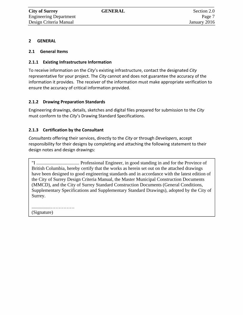
2.1.3 Certification by the Consultant
Consultants offering their services, directly to the City or through Developers, accept responsibility for their designs by completing and attaching the following statement to their design notes and design drawings:
"I .................................... Professional Engineer, in good standing in and for the Province of British Columbia, hereby certify that the works as herein set out on the attached drawings have been designed to good engineering standards and in accordance with the latest edition of the City of Surrey Design Criteria Manual, the Master Municipal Construction Documents (MMCD), and the City of Surrey Standard Construction Documents (General Conditions, Supplementary Specifications and Supplementary Standard Drawings), adopted by the City of Surrey. ................…………… (Signature)
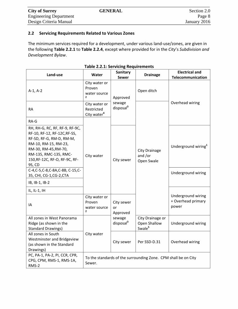
City of Surrey GENERAL Section 2.0 Engineering Department Page 8 Design Criteria Manual January 2016 2.2 Servicing Requirements Related to Various Zones
The minimum services required for a development, under various land‐use/zones, are given in the following Table 2.2.1 to Table 2.2.4, except where provided for in the City’s Subdivision and Development Bylaw.
Table 2.2.1: Servicing Requirements
Land‐use Water Sanitary Sewer
Drainage Electrical and
Telecommunication
A‐1, A‐2
City water or Proven water source 2 Approved
sewage disposal3
Open ditch
Overhead wiring
RA City water or Restricted City water4
City Drainage and /or Open Swale
RA‐G
City water
RH, RH‐G, RC, RF, RF‐9, RF‐9C, RF‐10, RF‐12, RF‐12C,RF‐SS, RF‐SD, RF‐G, RM‐D, RM‐M, RM‐10, RM‐15, RM‐23, RM‐30, RM‐45,RM‐70, RM‐135, RMC‐135, RMC‐150,RF‐12C, RF‐O, RF‐9C, RF‐9S, CD
City sewer
Underground wiring1
C‐4,C‐5,C‐8,C‐8A,C‐8B, C‐15,C‐35, CHI, CG‐1,CG‐2,CTA
Underground wiring
IB, IB‐1, IB‐2
IL, IL‐1, IH Underground wiring + Overhead primary power IA
City water or Proven water source 2
City sewer or Approved sewage disposal3
All zones in West Panorama Ridge (as shown in the Standard Drawings)
City water
City Drainage or Open Shallow Swale5
Underground wiring
All zones in South Westminster and Bridgeview (as shown in the Standard Drawings)
City sewer Per SSD‐D.31 Overhead wiring
PC, PA‐1, PA‐2, PI, CCR, CPR, CPG, CPM, RMS‐1, RMS‐1A, RMS‐2
To the standards of the surrounding Zone. CPM shall be on City Sewer.
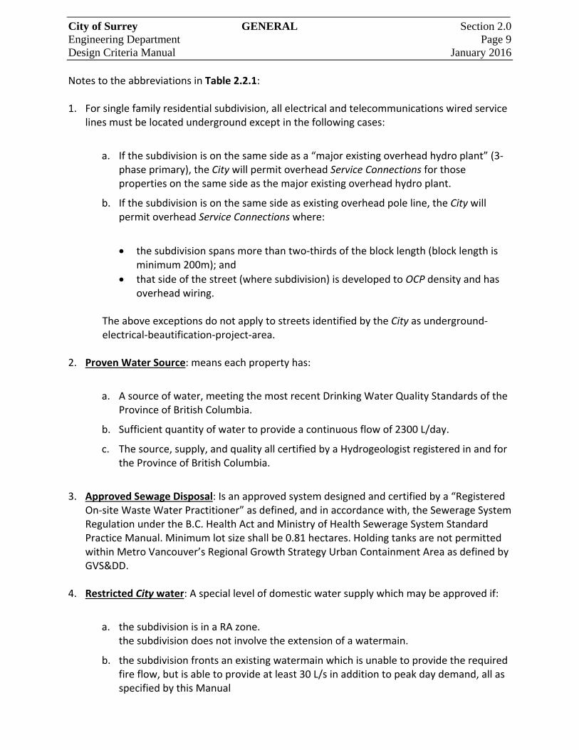
City of Surrey GENERAL Section 2.0 Engineering Department Page 9 Design Criteria Manual January 2016 Notes to the abbreviations in Table 2.2.1: 1. For single family residential subdivision, all electrical and telecommunications wired service
lines must be located underground except in the following cases:
a. If the subdivision is on the same side as a “major existing overhead hydro plant” (3‐phase primary), the City will permit overhead Service Connections for those properties on the same side as the major existing overhead hydro plant.
b. If the subdivision is on the same side as existing overhead pole line, the City will permit overhead Service Connections where:
the subdivision spans more than two‐thirds of the block length (block length is minimum 200m); and
that side of the street (where subdivision) is developed to OCP density and has overhead wiring.
The above exceptions do not apply to streets identified by the City as underground‐
electrical‐beautification‐project‐area. 2. Proven Water Source: means each property has:
a. A source of water, meeting the most recent Drinking Water Quality Standards of the Province of British Columbia.
b. Sufficient quantity of water to provide a continuous flow of 2300 L/day.
c. The source, supply, and quality all certified by a Hydrogeologist registered in and for the Province of British Columbia.
3. Approved Sewage Disposal: Is an approved system designed and certified by a “Registered
On‐site Waste Water Practitioner” as defined, and in accordance with, the Sewerage System Regulation under the B.C. Health Act and Ministry of Health Sewerage System Standard Practice Manual. Minimum lot size shall be 0.81 hectares. Holding tanks are not permitted within Metro Vancouver’s Regional Growth Strategy Urban Containment Area as defined by GVS&DD.
4. Restricted City water: A special level of domestic water supply which may be approved if:
a. the subdivision is in a RA zone. the subdivision does not involve the extension of a watermain.
b. the subdivision fronts an existing watermain which is unable to provide the required fire flow, but is able to provide at least 30 L/s in addition to peak day demand, all as specified by this Manual
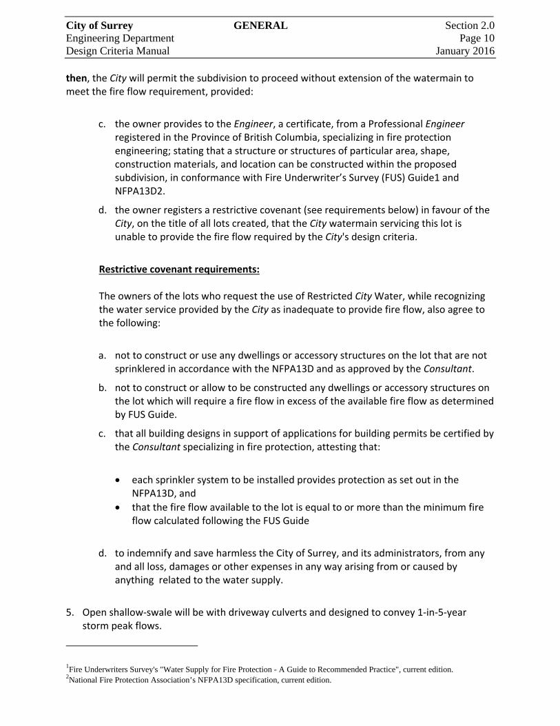
City of Surrey GENERAL Section 2.0 Engineering Department Page 10 Design Criteria Manual January 2016 then, the City will permit the subdivision to proceed without extension of the watermain to meet the fire flow requirement, provided:
c. the owner provides to the Engineer, a certificate, from a Professional Engineer registered in the Province of British Columbia, specializing in fire protection engineering; stating that a structure or structures of particular area, shape, construction materials, and location can be constructed within the proposed subdivision, in conformance with Fire Underwriter’s Survey (FUS) Guide1 and NFPA13D2.
d. the owner registers a restrictive covenant (see requirements below) in favour of the City, on the title of all lots created, that the City watermain servicing this lot is unable to provide the fire flow required by the City's design criteria.
Restrictive covenant requirements: The owners of the lots who request the use of Restricted City Water, while recognizing the water service provided by the City as inadequate to provide fire flow, also agree to the following:
a. not to construct or use any dwellings or accessory structures on the lot that are not sprinklered in accordance with the NFPA13D and as approved by the Consultant.
b. not to construct or allow to be constructed any dwellings or accessory structures on the lot which will require a fire flow in excess of the available fire flow as determined by FUS Guide.
c. that all building designs in support of applications for building permits be certified by the Consultant specializing in fire protection, attesting that:
each sprinkler system to be installed provides protection as set out in the NFPA13D, and
that the fire flow available to the lot is equal to or more than the minimum fire flow calculated following the FUS Guide
d. to indemnify and save harmless the City of Surrey, and its administrators, from any and all loss, damages or other expenses in any way arising from or caused by anything related to the water supply.
5. Open shallow‐swale will be with driveway culverts and designed to convey 1‐in‐5‐year
storm peak flows.
1Fire Underwriters Survey's "Water Supply for Fire Protection - A Guide to Recommended Practice", current edition. 2National Fire Protection Association’s NFPA13D specification, current edition.
City of Surrey GENERAL Section 2.0 Engineering Department Page 11 Design Criteria Manual January 2016
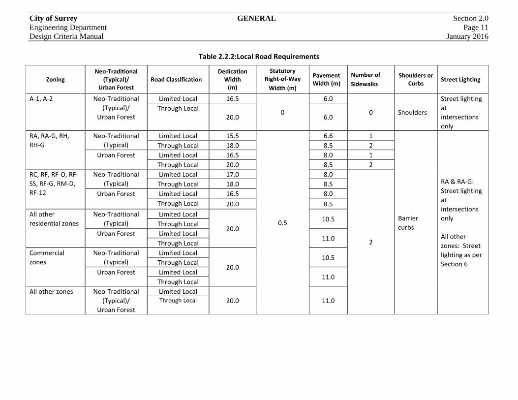
Table 2.2.2:Local Road Requirements
Zoning Neo‐Traditional
(Typical)/ Urban Forest
Road Classification Dedication Width (m)
Statutory Right‐of‐Way
Width (m)
Pavement Width (m)
Number of
Sidewalks
Shoulders or Curbs
Street Lighting
A‐1, A‐2 Neo‐Traditional
(Typical)/
Urban Forest
Limited Local 16.5
0
6.0
0 Shoulders
Street lighting
at
intersections
only
Through Local 20.0 6.0
RA, RA‐G, RH,
RH‐G
Neo‐Traditional
(Typical)
Limited Local 15.5
0.5
6.6 1
Barrier
curbs
RA & RA‐G:
Street lighting
at
intersections
only
All other
zones: Street
lighting as per
Section 6
Through Local 18.0 8.5 2
Urban Forest Limited Local 16.5 8.0 1
Through Local 20.0 8.5 2
RC, RF, RF‐O, RF‐
SS, RF‐G, RM‐D,
RF‐12
Neo‐Traditional
(Typical)
Limited Local 17.0 8.0
2
Through Local 18.0 8.5
Urban Forest Limited Local 16.5 8.0
Through Local 20.0 8.5
All other
residential zones
Neo‐Traditional
(Typical)
Limited Local
20.0
10.5 Through Local
Urban Forest Limited Local 11.0
Through Local
Commercial
zones
Neo‐Traditional
(Typical)
Limited Local
20.0
10.5 Through Local
Urban Forest Limited Local 11.0
Through Local
All other zones Neo‐Traditional
(Typical)/
Urban Forest
Limited Local
20.0 11.0 Through Local

City of Surrey GENERAL Section 2.0 Engineering Department Page 12 Design Criteria Manual January 2016
Table 2.2.3: Major Road Requirements
Road Classification
Area Dedication Width (m)
Statutory Right‐of‐Way Width (m)
Roadway Width (m)
Number of
Sidewalks
Shoulders or
Curbs Street Lights
Collector All areas except ALR
24.0 0.5 14.0 2
Barrier
Curbs As per Section 6.8
ALR area Varies 11.0 Varies Shoulders At intersections only
Arterial
All areas
except ALR
4 lanes 30.0
0.5
20.0
2 Barrier
curbs As per Section 6.8 6 lanes 37.0 27.0
Rapid Transit 42.0 32.0
ALR area
4 lanes 30.0
Varies
20.0
Varies Shoulders At intersections only 6 lanes 37.0 27.0
Rapid Transit 42.0 32.0
Also see notes below
Table 2.2.4 Special Road Requirements
Area Road Classification Dedication
Width (m) Roadway Width (m)
Number of
Sidewalks
Shoulders
or
Curbs
Street Lights
South
Westminster &
Bridgeview
Limited Local 20.0 11.0
1
Shoulders
Street lighting as per
Section 6.8 Through Local 2
West Panorama
Limited Local 16.5
6.0
0
Low profile street
lighting at
intersections of
collector &Arterial
Roads and in front of
public buildings only
Through Local
20.0
Collector 7.3
Also see notes below

City of Surrey GENERAL Section 2.0 Engineering Department Page 13 Design Criteria Manual January 2016 Notes related to Table 2.2.2, Table 2.2.3, and Table 2.2.4 are given below:
a. Where construction of a half‐road is required, and the other half does not yet exist, the minimum pavement width will be 6.0m and the minimum road dedication will be 11.5m, except in commercial and industrial zones where the minimum pavement width will be 8.0m and the minimum road dedication will be 13.5m. It is preferred that these road dedications be consistent with the ultimate alignment of the road and not offset.
b. In order to provide traffic turn Lane channelization and/or bus bays, additional pavement width and road dedication may be required at intersections with Arterial and Collector Roads.
c. To accommodate parking in cul‐de‐sacs, additional pavement width and road dedication are required.
d. For non‐standard road allowance widths, refer to the “Surrey Major Road Allowance Map” – Schedule K of the Surrey Subdivision and Development Bylaw.
e. Some roads may have additional statutory right‐of‐way requirements, not indicated in the above Tables, for purposes such as multi‐use pathways, landscape buffers, etc.
f. If a Public Utility (e.g. BC Hydro, Telus) cannot be accommodated in its preferred location within the road dedication provided in accordance with the above Tables, it must secure additional or separate road dedication or statutory right‐of‐way for this purpose.
g. Where the back of a sidewalk is proposed within 0.5m of a road dedication property line, statutory right‐of‐ways on the private lands may be required to permit the City to have unencumbered maintenance access to sewer inspection chambers and to the water shut‐off valves. Relocation of the inspection chambers and/or water shut‐off‐valves, or the granting of additional right‐of‐way widths will be required where it is determined that the utility was installed outside the limits of the original statutory right‐of way.
2.3 Design Populations
2.3.1 Design Population by Zoning or Land‐use Designation
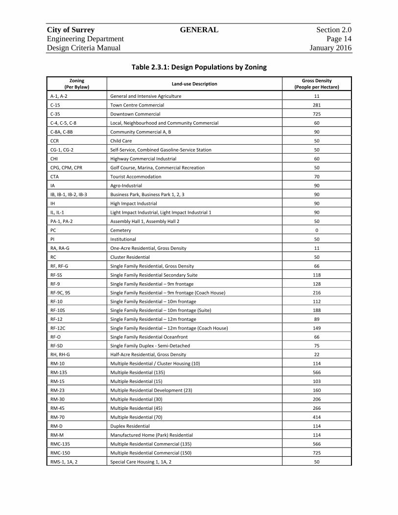
If the number of lots or units is unknown, use the Gross Density / Equivalent Population Factor in Table 2.3.1 to calculate population estimates.
City of Surrey GENERAL Section 2.0 Engineering Department Page 14 Design Criteria Manual January 2016
Table 2.3.1: Design Populations by Zoning
Zoning (Per Bylaw)
Land‐use Description Gross Density
(People per Hectare)
A‐1, A‐2 General and Intensive Agriculture 11
C‐15 Town Centre Commercial 281
C‐35 Downtown Commercial 725
C‐4, C‐5, C‐8 Local, Neighbourhood and Community Commercial 60
C‐8A, C‐8B Community Commercial A, B 90
CCR Child Care 50
CG‐1, CG‐2 Self‐Service, Combined Gasoline‐Service Station 50
CHI Highway Commercial Industrial 60
CPG, CPM, CPR Golf Course, Marina, Commercial Recreation 50
CTA Tourist Accommodation 70
IA Agro‐Industrial 90
IB, IB‐1, IB‐2, IB‐3 Business Park, Business Park 1, 2, 3 90
IH High Impact Industrial 90
IL, IL‐1 Light Impact Industrial, Light Impact Industrial 1 90
PA‐1, PA‐2 Assembly Hall 1, Assembly Hall 2 50
PC Cemetery 0
PI Institutional 50
RA, RA‐G One‐Acre Residential, Gross Density 11
RC Cluster Residential 50
RF, RF‐G Single Family Residential, Gross Density 66
RF‐SS Single Family Residential Secondary Suite 118
RF‐9 Single Family Residential – 9m frontage 128
RF‐9C, 9S Single Family Residential – 9m frontage (Coach House) 216
RF‐10 Single Family Residential – 10m frontage 112
RF‐10S Single Family Residential – 10m frontage (Suite) 188
RF‐12 Single Family Residential – 12m frontage 89
RF‐12C Single Family Residential – 12m frontage (Coach House) 149
RF‐O Single Family Residential Oceanfront 66
RF‐SD Single Family Duplex ‐ Semi‐Detached 75
RH, RH‐G Half‐Acre Residential, Gross Density 22
RM‐10 Multiple Residential / Cluster Housing (10) 114
RM‐135 Multiple Residential (135) 566
RM‐15 Multiple Residential (15) 103
RM‐23 Multiple Residential Development (23) 160
RM‐30 Multiple Residential (30) 206
RM‐45 Multiple Residential (45) 266
RM‐70 Multiple Residential (70) 414
RM‐D Duplex Residential 114
RM‐M Manufactured Home (Park) Residential 114
RMC‐135 Multiple Residential Commercial (135) 566
RMC‐150 Multiple Residential Commercial (150) 725
RMS‐1, 1A, 2 Special Care Housing 1, 1A, 2 50

City of Surrey GENERAL Section 2.0 Engineering Department Page 15 Design Criteria Manual January 2016 If the number of lots or units is known, use the household population estimates as outlined in Table 2.3.2, with the inclusion of one secondary suite or coach house per detached house for new development areas as shown in Figure 2.3.1.
Table 2.3.2: Household Population Area and Housing Type
Area Detached Townhouse Apartment
Secondary Suite/Coach
House
Number of People per dwelling unit
City Centre 3.62 2.85 1.88 1.93
Cloverdale 3.56 2.69 1.43 1.77
Fleetwood 3.64 2.84 1.82 1.82
Guildford 3.60 2.72 2.23 1.91
Newton 3.66 2.88 2.26 1.95
South Surrey 2.96 2.62 1.36 1.45
Whalley 3.62 2.85 1.88 1.93
2.4 Expansion of the City’s Infrastructure
Expansion of the City infrastructure system or extension of a main must be carried out in compliance with the City’s applicable Bylaws. The pre‐servicing of future, anticipated lots is permitted at the Developer’s cost and at the Engineer’s approval. Lands receiving these non‐functioning services will be required to remove the services, at the Developer’s cost, should they be subsequently found to be in conflict with future driveway locations, or other utilities, or deemed to be in a location or of a size that does not conform to the future development of the land.
2.5 Utility Alignments and Services
The Consultant is to identify existing utility offsets and to plan new and future works utilizing constant off‐sets. Along any roadway or utility corridor, the varying of utility off‐sets is to be avoided. The Engineer may permit utility off‐sets to vary only under unique circumstances. In all instances, the Consultant is to ensure that the crossing of one utility and/or service over another is at an angle of between 45 and 90 degrees.
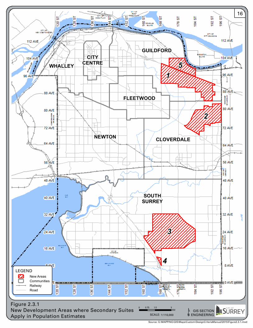
5
4
1
3
2
CITYCENTRE
SOUTHSURREY
WHALLEY
FLEETWOOD
CLOVERDALENEWTON
GUILDFORD
0 1.5 30.75KM
Figure 2.3.1 New Development Areas where Secondary SuitesApply in Population Estimates
GIS SECTIONENGINEERINGSCALE: 1:110,000
LEGEND
New AreasCommunitiesRailwayRoad
Source: G:\MAPPING\GIS\Maps\Custom\DesignCriteriaManual\2015\Figure2.3.1.mxd
16
City of Surrey GENERAL Section 2.0 Engineering Department Page 17 Design Criteria Manual January 2016
2.5.1 Horizontal Separation
Fraser Health Authority (FHA) requires minimum 3.0m horizontal separation between watermains and sanitary and storm sewers. If installation of utilities is constrained by space availability, depending on the soil characteristics, FHA may consider lesser separation between mains provided:
a. If water and sewer mains are installed in separate trenches: Install the watermain such that the invert is minimum 0.5m above the crown of the sanitary sewer or storm sewer, or
b. If water and sewer mains are installed in a single trench: Install watermain on a bench of undisturbed earth minimum 0.5m above the crown of the sanitary sewer or the storm sewer.
In either situation, wrap the joints with heat shrink plastic, or pack with compound and wrap with petrolatum tape in accordance with the latest version of AWWA Standards C217, and C214 or C209.
2.5.2 Vertical Separation
Where a watermain crosses a sanitary sewer or storm sewer:
a. Install the watermain above the sewer with a minimum clearance of 0.5m; and
b. Wrap the joints of the watermain, over a length extending 3m either side of the sewer crossing, with material stated in 2.5.1.
If vertical separation as mentioned above is not possible, subject to the approval of the FHA:
a. Construct sewer with PVC pipe, center sewer pipe below crossing to maximize offset distance of joints, and pressure test to assure air tightness, or
b. Wrap sewer joints with material stated in 2.5.1.
2.5.3 Sewers in Common Trench
Sanitary and storm sewers may be installed in a common trench provided the design adequately addresses the following:
a. Interference with Service Connections,
b. Stability of the benched portion of the trench,
c. Conflict with manholes and appurtenances, and
City of Surrey GENERAL Section 2.0 Engineering Department Page 18 Design Criteria Manual January 2016
d. Horizontal clearance: minimum 1.0m between outside of sewers or minimum 3.0m between manholes whichever greater is required.
2.5.4 Utility Services
Engineering drawings submitted to the City for review are to identify all existing water, storm and sanitary services greater than 30 years old, and their abandonment may be incorporated into a new Servicing Agreement at the discretion of the Engineer. Existing storm and sanitary services that are less than 30 years old, and are proposed to be retained, are to be video inspected by the Consultant prior to commencement of the construction phase to ensure no existing deficiencies exist.
2.5.5 Cul‐de‐sac Servicing
When designing a utility main servicing properties in a cul‐de‐sac,
a. Minimize the number of crossings with other utilities, and
b. Obtain approval from the Engineer if a service length exceeds 20m.
2.5.6 Utilities Crossing Provincial Highways, Major Roads and Railways
Watermains, sanitary sewers and storm sewers crossing Provincial Highways, the major municipal roads identified in Table 2.5.1, and railways shall be a carrier pipe within a casing pipe as specified below:
a. A steel carrier pipe shall be provided and designed to meet the applicable loading and the requirements of the authority having jurisdiction. The size of the casing pipe must be at least 25% larger than the outside diameter of the pipe bell.
b. Casing spacers and end seals to be as per the City’s Supplementary Specifications.
c. Provide a minimum 10m long unrestricted working space, and Right‐of‐Way as required, in the axis direction of the pipe, beyond one end of the casing, to withdraw or insert the carrier pipe.
d. Provide adequate working space to disconnect the carrier pipe at the opposite end of the casing.

City of Surrey GENERAL Section 2.0 Engineering Department Page 19 Design Criteria Manual January 2016
Table 2.5.1: Highways that Require Additional Design Criteria
Provincial Highway
Municipal Road
Highway No. 1 Scott Road from King George Boulevard to 96 Avenue
Highway No. 10 King George Boulevard from Pattullo Bridge to 54 Avenue
Highway No. 15 King George Boulevard from 36 Avenue to 8 Avenue
Highway No. 17 152 Street from Ferguson Diversion to 54 Avenue
Highway No. 99 152 Street from Nicomekl River to 16 Avenue
108 Avenue from King George Boulevard to Ferguson Diversion
Ferguson Diversion from 108 Avenue to 152 Street
104 Avenue from King George Boulevard to 160 Street
Fraser Highway from King George Boulevard to address 17127
Fraser Highway from 178 Street to 196 Street
When a lot fronts a watermain or sewer on one of these roads, and the utility is on the opposite side of the road, the watermain and sewer are not considered to be fronting the lot, and as such the property is not entitled to a Service Connection. Service Connections on these roads will either be made to the utility on the rear Lane, if a Lane exists and approved by the City, or to the utility on the near side of the road. In the absence of near side utility or rear Lane service, a new watermain or sewer shall be installed.
2.5.7 Gas Main Routing
Gas mains will not be permitted in Lanes, unless approved by the Engineer, due to the congestion of other buried utilities, and the proximity of the property lines. Gas main corridors, in general, should allow for a 1:1 slope of influence/conflict between the depth of other buried utilities and the depth of the gas main.
2.5.8 Utility Rights‐of‐Way Width
Where specifically approved by the Engineer to locate a City utility within a statutory Right‐of‐Way (R.O.W.), the required widths of the statutory R.O.W. and the minimum widths will be as noted in Table 2.5.2:

City of Surrey GENERAL Section 2.0 Engineering Department Page 20 Design Criteria Manual January 2016
Table 2.5.2: Required widths of R.O.W.
No. of Sewer and Water mains within
the R.O.W. R.O.W. Width Required
Minimum R.O.W. Width Required
For Water
For Sanitary Sewer & Drainage
Single main 2 x (Depth surface to crown of the pipe) + Trench Width
3m 5m
Two mains in same trench
2 x (Depth surface to crown of deeper pipe) + Trench Width
5m
Two or more mains separate adjacent trenches
Sum of the R.O.W. widths required for each single main + Separation between trenches
6m
R.O.W Layout and other requirements:
a. In all cases, the width of rights‐of‐way shall be sufficient to permit an open excavation, with side slopes in accordance with the WorkSafeBC regulations, without impacting on or endangering adjacent structures.
b. When the sewer or water main is installed within a City road allowance but the distance from the property line to the center of the main is less than one half of the required width for a single service, the difference shall be provided as right‐of‐way on the property.
c. If the sewer or water main is installed in a private property the entire width of the R.O.W. will be within that private property.
d. Sanitary trunk and interceptor sewers shall have rights‐of‐way wide enough for future widening and/or twinning. Allow R.O.W. width considering mains in separate adjacent trenches.
e. Unless approved otherwise by the Engineer, the maximum depth of sewers in a R.O.W. will be 3.5m from finished ground surface to the pipe invert.
f. Excavations must be considered such that minimum safe distances exist, or are established to adjacent, existing or future building footings based on a safe angle of repose from the limits of the excavation (The Consultant will provide the details in the cross sections on the design drawings). The cross‐sections must identify the proposed minimum building set‐backs from the property lines.). Where conflicts are anticipated, the Consultant will submit a letter report to the Engineer outlining the anticipated conflicts.
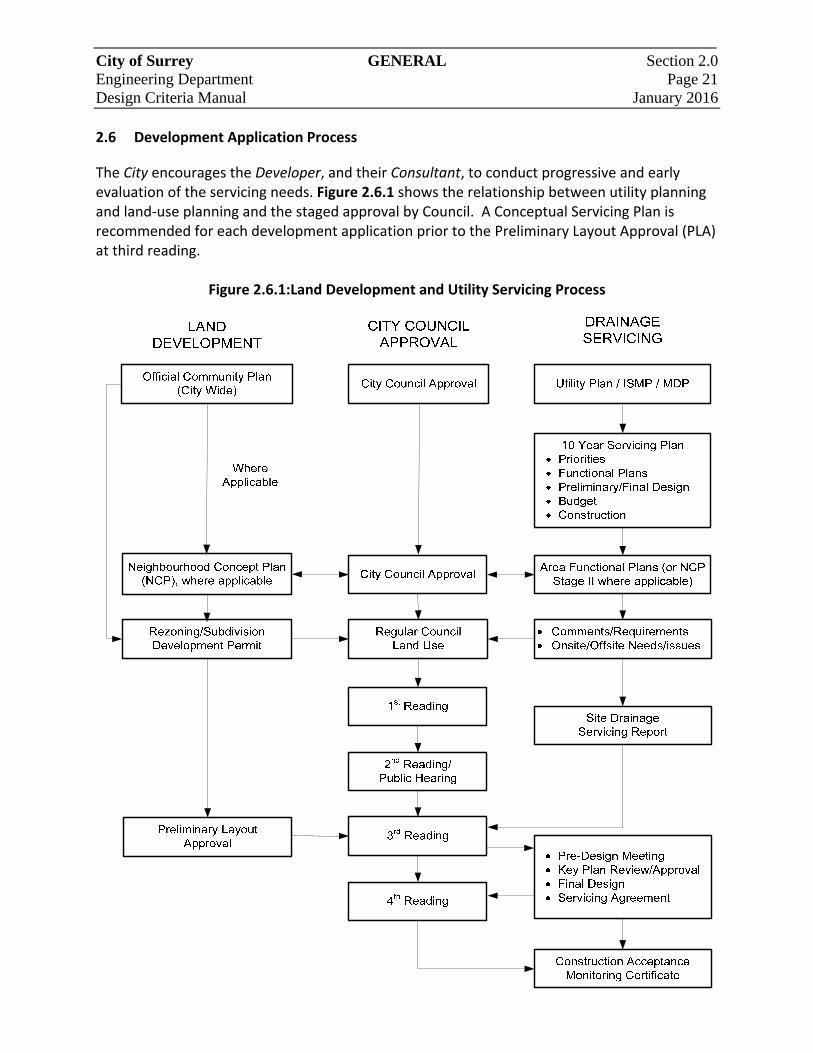
City of Surrey GENERAL Section 2.0 Engineering Department Page 21 Design Criteria Manual January 2016 2.6 Development Application Process
The City encourages the Developer, and their Consultant, to conduct progressive and early evaluation of the servicing needs. Figure 2.6.1 shows the relationship between utility planning and land‐use planning and the staged approval by Council. A Conceptual Servicing Plan is recommended for each development application prior to the Preliminary Layout Approval (PLA) at third reading.
Figure 2.6.1:Land Development and Utility Servicing Process

City of Surrey GENERAL Section 2.0 Engineering Department Page 22 Design Criteria Manual January 2016 In situations where no Utility Plan and/or ISMP / MDP exists or where new development is proposed before the completion of the required works recommended in the aforementioned plans, the Developer is required to complete those works necessary to service the development. Interim measures may be considered providing that they can be practically achieved and protect the downstream system. Interim stormwater detention in NCP areas will only be considered if the land for the ultimate drainage facility is secured in favour of the City.
SECTION 3
Water Distribution System
City of Surrey WATER DISTRIBUTION Section 3.0 Engineering Department SYSTEM Page 23 Design Criteria Manual January 2016
3 WATER DISTRIBUTION SYSTEM
3.1 Demands and Flows
3.1.1 Per Capita Demands
For system analysis, the following Per Capita Demands shall be used:
a. Base Day Demand(BDD) – average consumption from December to February BDD = 300 L/day/capita
b. Average Day Demand (ADD) – averaged consumption over 365 days
ADD = 500 L/day/capita
c. Maximum Day Demand(MDD)– highest daily consumption MDD = 1,000 L/day/capita
d. Peak Hour Demand(PHD) – highest hourly demand in the last ten years extrapolated
to 24 hr. PHD = 2,000 L/day/capita
For system analysis, the total demand [Q design] will be the greater of the following:
a. Qdesign = MDD + FF MDD for the population or ‘equivalent population’ plus the fire flow (FF) requirement in L/s, or
b. Qdesign = PHD PHD for the population or ‘equivalent population’ in L/s.
3.1.2 Population Estimates and Equivalents:
Water demands for residential areas shall be estimated using the population estimates, by housing type and area, including provision for secondary suites and coach houses, as provided in Section 2.3 of this manual. Water demands for commercial and industrial areas will be estimated using the “population equivalents” estimates derived by using the Gross Density / Equivalent Population Factor, by zoning designation, as discussed in Section 2.3, with exception to all industrial zones and land‐uses for which an equivalent factor of 45 people per hectare shall be used. For a known water user where a higher water demand is expected, the water demand from a similar industrial application shall be used.
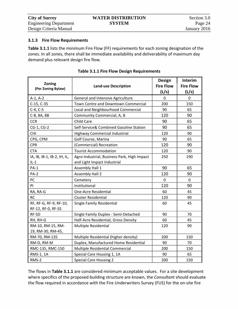
City of Surrey WATER DISTRIBUTION Section 3.0 Engineering Department SYSTEM Page 24 Design Criteria Manual January 2016 3.1.3 Fire Flow Requirements
Table 3.1.1 lists the minimum Fire Flow (FF) requirements for each zoning designation of the zones. In all zones, there shall be immediate availability and deliverability of maximum day demand plus relevant design fire flow.
Table 3.1.1 Fire Flow Design Requirements
Zoning (Per Zoning Bylaw)
Land‐use Description
Design Interim Fire Flow (L/s)
Fire Flow (L/s)
A‐1, A‐2 General and Intensive Agriculture 0 0
C‐15, C‐35 Town Centre and Downtown Commercial 200 150
C‐4, C‐5 Local and Neighbourhood Commercial 90 65
C‐8, 8A, 8B Community Commercial, A, B 120 90
CCR Child Care 90 65
CG‐1, CG‐2 Self‐Service& Combined Gasoline Station 90 65
CHI Highway Commercial Industrial 120 90
CPG, CPM Golf Course, Marina 90 65
CPR (Commercial) Recreation 120 90
CTA Tourist Accommodation 120 90
IA, IB, IB‐1, IB‐2, IH, IL,
IL‐1
Agro‐Industrial, Business Park, High Impact
and Light Impact Industrial
250 190
PA‐1 Assembly Hall 1 90 65
PA‐2 Assembly Hall 2 120 90
PC Cemetery 0 0
PI Institutional 120 90
RA, RA‐G One‐Acre Residential 60 45
RC Cluster Residential 120 90
RF, RF‐G, RF‐9, RF‐10,
RF‐12, RF‐0, RF‐SS
Single Family Residential 60 45
RF‐SD Single Family Duplex ‐ Semi‐Detached 90 70
RH, RH‐G Half‐Acre Residential, Gross Density 60 45
RM‐10, RM‐15, RM‐
19, RM‐30, RM‐45,
Multiple Residential 120 90
RM‐70, RM‐135 Multiple Residential (higher density) 200 150
RM‐D, RM‐M Duplex, Manufactured Home Residential 90 70
RMC‐135, RMC‐150 Multiple Residential Commercial 200 150
RMS‐1, 1A Special Care Housing 1, 1A 90 65
RMS‐2 Special Care Housing 2 200 150
The flows in Table 3.1.1 are considered minimum acceptable values. For a site development where specifics of the proposed building structure are known, the Consultant should evaluate the flow required in accordance with the Fire Underwriters Survey (FUS) for the on‐site fire
City of Surrey WATER DISTRIBUTION Section 3.0 Engineering Department SYSTEM Page 25 Design Criteria Manual January 2016 protection of the development. The Fire Flow requirement will be the greater of the values listed in the above table and the FUS requirements. Design of new extensions to the water system will be based on design of Fire Flow for the site under consideration, with the available Fire Flow being withdrawn from the water main fronting the principal entrance of the building or the development. Interim Fire Flow values may be used only if the design fire flow can be achieved through: any of the water system upgrades identified within the City’s current 10‐year Servicing Plan; or, system looping proposed by the Developer within their own development. If the maximum fire flow available within the City’s distribution system at the site is determined to be less than the flow required for the fire protection of the site, the Developer is responsible to either upgrade the water system sufficiently to provide the higher fire protection necessary for the site, or, take whatever other measures are necessary to reduce fire protection requirements of the proposed development to match the level of protection available from the City’s distribution system.
3.2 Water System Analysis
Determination of sufficiency and adequacy of the existing system may be proven using the analytical methods given in the following sections. This analytical methodology will apply to systems with Distribution Mains only. For analysis of systems with Feeder Mains and pressure reducing valve stations, the Consultant will consult with the Engineer.
3.2.1 Existing Water Distribution System
For analysis of the existing distribution system, the flow [Q available] at the design location will be determined using supply sources and assuming their input heads as described in Section 3.2.4. No other demands need to be imposed at any other locations.
3.2.2 New Water Distribution System
For analysis of the proposed expansion of the distribution system, the availability of the total demand [Q design] will be tested at the most critical location of the system expansion under consideration. Existing water mains may be utilized for analysis if they are not to be abandoned as directed by the Engineer. However, the Consultant must ensure that the system configuration is set up as it is supposed to operate under ultimate conditions including pressure zone separations.
City of Surrey WATER DISTRIBUTION Section 3.0 Engineering Department SYSTEM Page 26 Design Criteria Manual January 2016 3.2.3 Hazen‐Williams Formula
The analysis of the pipe network system will be carried out using the Hazen‐Williams equation, and in all instances the following values shall be used for the Hazen‐Williams’ coefficient:
C = 125 for all water mains 250mm diameter and larger C = 100 for all water mains 200mm diameter and smaller
3.2.4 The Source Nodes
The supply source locations to be used for analysis as starting locations are as follows:
a. For design of Feeder Mains, the pertinent pump station or PRV station will be taken as the supply source with the discharge head at the station as the starting input head.
b. For design of Distribution Mains, the supply source may be assumed to be:
for Q design < 120 L/s, the tie‐in point(s) to the nearest 300mm or larger diameter water main(s) continuously tied to the supply source.
for Q design > 120 L/s, the tie‐in point to the nearest Feeder Main continuously tied to the supply source.
The input head(s) at the supply source will be 70% of the (respective) static head (e.g. 70% of the difference between the hydraulic grade elevation of the pressure zone and the ground elevation of the supply source.)
3.2.5 Pressure Zones:
The proposed HGL of the various pressure zones are shown in Figure 3.2.1. These ultimate HGL’s will be used in all analysis notwithstanding the fact that some of these zones may not yet be set. The Consultant will verify, with the Engineer, the accuracy of this information prior to commencing design or analysis.

80 AVE
192 S
T
8 AVE
196 S
T
88 AVE
72 AVE
0 AVE
64 AVE
0 AVE
24 AVE
56 AVE
32 AVE
16 AVE
40 AVE
16 AVE
32 AVE19
6 ST
192 S
T
184 S
T
112 AVE
80 AVE
8 AVE
88 AVE
176 S
T
104 AVE
168 S
T
160 S
T
40 AVE
56 AVE
72 AVE15
2 ST
144 S
T
24 AVE
96 AVE12
8 ST
120 S
T
96 AVE
48 AVE
112 AVE
136 S
T
128 S
T
136 S
T
120 S
T
144 S
T
104 AVE
64 AVE
152 S
T
168 S
T
176 S
T48 AVE
160 S
T
184 S
T
BOUNDARYBAY
WHITE ROCK
PACIFIC(TRUCK)BORDER
CROSSING
BARNSTONISLAND
CITY OFPITT MEADOWS
DOUGLASISLAND
DOUGLAS(PEACE ARCH)
BORDERCROSSING
CITY OF
NEW WESTMINSTER
MUDBAY
CITY OFCOQUITLAM
FRASER RIVER
WASHINGTON
TOWN
SHIP
OF LA
NGLE
Y
C H A N N E L
CORPORATIONOF DELTA
CORP
ORAT
ION
OF D
ELTA
SEMIAHMOOBAY
TOWN
SHIP
OF LA
NGLE
Y
ANNA
CIS IS
LAND
PATULLOBRIDGE
BRITISH COLUMBIA
FRASER RIVER
F R A SE R R
IVE R
PORT MANNBRIDGE
CITY OFPORT
COQUITLAM
CITY
OF
LANG
LEY
80mHGL
120mHGL
80mHGL
80mHGL
80mHGL
110mHGL
110mHGL120m
HGL
80mHGL
80mHGL
80mHGL
90mHGL
90mHGL
90mHGL
115mHGL
90mHGL
80mHGL
73mHGL
90mHGL
95mHGL
90mHGL
135mHGL
145mHGL95m
HGL
90mHGL
90mHGL
135mHGL
90mHGL
110mHGL
142mHGL
151mHGL
0 1.5 30.75KM
Figure 3.2.1Pressure Zones
GIS SECTIONENGINEERINGSCALE: 1:110,000
LEGEND
Pressure ZonesRailwayRoad
¹Source: G:\MAPPING\GIS\Maps\Custom\DesignCriteriaManual\2015\Figure3.2.1.mxd
27
City of Surrey WATER DISTRIBUTION Section 3.0 Engineering Department SYSTEM Page 28 Design Criteria Manual January 2016
3.2.1 Residual Pressure Requirements
It is intended that the City’s distribution system will provide an operating pressure head of 28m minimum at all locations during PHD. When analyzing the system on the basis of PHD, a minimum residual of 28m hydraulic head must be maintained at all locations. The City seeks to maintain a minimum of 14m residual head at the discharge side of fire hydrants at MDD plus Fire Flow conditions. In general, if the flow from the hydrant does not exceed 60 L/s, the hydraulic head required at the water main upstream of the hydrant remains the same at 14m. If the Consultant requires the flow from a single hydrant to exceed 60 L/s, the hydraulic head required at the water main upstream of the fire hydrant will have to be greater to account for the head losses through the hydrant. The maximum flow rate from a hydrant will not exceed 120 L/s. For flow rates not detailed above, or situations where multiple hydrants are required to deliver the Fire Flow, the minimum hydraulic head can be calculated as the greater of 14m or 7m plus the head loss through the hydrant. Head loss through the hydrant(s) should be calculated as
Head Loss (hl) =1083(Qdesign)2
Where: hl = head loss (m) Qdesign = flow (m3/s)
The minimum hydraulic head for all locations beyond 400m of the subject hydrant is 21m.
3.2.2 Hydraulic Grade and Maximum Velocities:
The flow characteristics of the selected water main conveying the Q design will be as follows:
a. The hydraulic grade in mains larger than 250mm diameter will not exceed 0.5%.
b. The velocity of flow will not exceed 2 m/s for ultimate design flows, and where interim fire flow is permitted, the velocity of flow will not exceed 3.25 m/s.
City of Surrey WATER DISTRIBUTION Section 3.0 Engineering Department SYSTEM Page 29 Design Criteria Manual January 2016 3.3 Design of Water System Components
3.3.1 General
All water system components shall comply with respective AWWA standards and be designed so as to withstand all stresses, internal as well as external, whether caused by static pressures, dynamic pressures, transient pressures, thermal stresses, or stresses induced by vertical loads.
3.3.2 Watermains
3.3.2.1 Size
The minimum size of a new water main shall be 200mm diameter, except:
a. In the City and Town Centres where the minimum size of a new water main will be 250mm diameter (see Figure 3.3.1).
b. In the agricultural area where the minimum size will be 100mm diameter, and
c. On dead‐end roads, where no further extension of the distribution system is possible, mains less than 200mm diameter may be used for the last lengths not exceeding 100m. All watermains less than 200mm in diameter are to be ductile iron.
3.3.2.2 Location
Distribution Mains should be located as shown on the Standard Drawings, in a Highway. All non‐standard utility offsets are to be supported by a typical cross‐section showing all utilities and the ultimate road section. Where not technically feasible, as determined by the Engineer, water mains may be approved in side yard and rear yard statutory rights‐of‐way if:
a. The rights‐of‐way minimum width meets the requirements set out in Section 2.5.8;
b. The rights‐of‐way is capable of supporting the intended maintenance vehicles in all weather conditions; and
c. The rights‐of‐way includes an all‐weather road surface for service or maintenance.

CityCentre
SemiahmooTown Centre
GuildfordTown Centre
CloverdaleTown Centre
NewtonTown Centre
FleetwoodTown Centre
0 1.5 30.75KM
Figure 3.3.1City and Town Centres GIS SECTION
ENGINEERINGSCALE: 1:110,000 ¹
LEGEND
Town CentresCommunitiesRailwayRoad
Source: G:\MAPPING\GIS\Maps\Custom\DesignCriteriaManual\2015\Figure3.3.1.mxd
30
City of Surrey WATER DISTRIBUTION Section 3.0 Engineering Department SYSTEM Page 31 Design Criteria Manual January 2016 3.3.2.3 Looping
Water mains will be looped to avoid dead‐end mains. Dead‐end mains may be allowed at the discretion of the Engineer when all the following conditions are met:
a. The water main services Single Family Residential zoned lands;
b. The length of main is less than 100m; and
c. The maximum size of the main is 100mm.
To eliminate stagnant water conditions on dead end mains, water mains should be reduced in size after the last hydrant, and a small diameter service line should extend to houses being serviced beyond the hydrant.
The diameter of the water main for the purpose of looping shall be the same diameter as the water main that would normally be required if the main was located within a road/highway. As a minimum, the diameter of the water main for looping shall be 100mm or larger and the material may be HDPE.
3.3.2.4 Depth
Minimum cover over any water main pipe shall be 1.0m to the finished grade. For roads that have yet to be constructed, the ultimate finished grade must first be approximated through preliminary road design. Minimum cover over water main pipes crossing under ditches shall be 0.5m and be protected from ditch cleaning equipment by means of a pre‐cast concrete slab. Water mains will not be installed at depths greater than 1.5m, unless approved by the Engineer. 3.3.2.5 Grade
Minimum slope on a water main shall be 0.1%. When the slope of a water main equals or exceeds 10%, the water main shall be ductile iron and include a means to anchor the pipe.
July 11/16
City of Surrey WATER DISTRIBUTION Section 3.0 Engineering Department SYSTEM Page 32 Design Criteria Manual January 2016 3.3.2.6 Materials
The Consultant will ensure the pipe material is appropriate for the purpose and the surroundings. Ductile iron pipe, class 350 pipe, shall be used for all Feeder Mains and on all Arterial Roads. In addition, ductile iron pipe shall be used in all areas with compressible soils and in all seismic areas, and in these areas the pipe joints of all sizes will require a suitable form of mechanical restraints. Refer to Section 3.5 for material requirements in seismic areas. 3.3.2.7 Corrosion Protection
For the applicable areas as noted in Figure 3.3.2, corrosion protection for metallic pipes and a appurtenances shall be provided as follows:
a. Metallic pipelines installed in the “Areas corrosion protection required” shall have corrosion protection appropriately designed and constructed to prevent the corrosion of the metallic pipeline and appurtenances.
b. For metallic pipelines installed in the “Areas corrosion protection determined based on investigation”, geotechnical soil analysis must be carried out in the alignment of the pipelines to determine the corrosiveness of the native soils.
Notwithstanding the above, the Consultant will determine if corrosion investigation is required in other areas. Geotechnical soil analysis must be carried out based on the 10‐point method given under Appendix A of AWWA C105. Polyethylene encasement alone is not considered as an acceptable method of corrosion protection. Cathodic protection or other protection method would be required if the cumulative total based on the above soil test evaluation equal or exceed ten points.
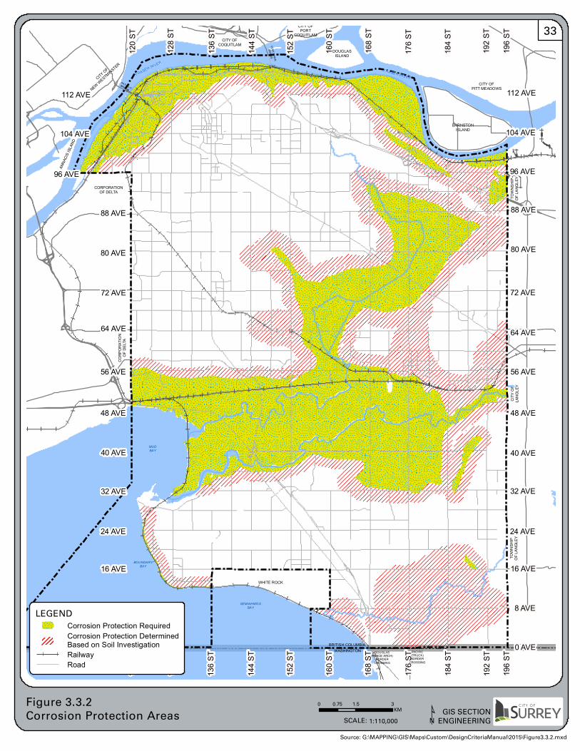
80 AVE
192 S
T
8 AVE
196 S
T
88 AVE
72 AVE
0 AVE
64 AVE
0 AVE
24 AVE
56 AVE
32 AVE
16 AVE
40 AVE
16 AVE
32 AVE19
6 ST
192 S
T
184 S
T
112 AVE
80 AVE
8 AVE
88 AVE
176 S
T
104 AVE
168 S
T
160 S
T
40 AVE
56 AVE
72 AVE15
2 ST
144 S
T
24 AVE
96 AVE12
8 ST
120 S
T
96 AVE
48 AVE
112 AVE
136 S
T
128 S
T
136 S
T
120 S
T
144 S
T
104 AVE
64 AVE
152 S
T
168 S
T
176 S
T48 AVE
160 S
T
184 S
T
BOUNDARYBAY
WHITE ROCK
PACIFIC(TRUCK)BORDER
CROSSING
BARNSTONISLAND
CITY OFPITT MEADOWS
DOUGLASISLAND
DOUGLAS(PEACE ARCH)
BORDERCROSSING
CITY OF
NEW WESTMINSTER
MUDBAY
CITY OFCOQUITLAM
FRASER RIVER
WASHINGTON
TOWN
SHIP
OF LA
NGLE
Y
C H A N N E L
CORPORATIONOF DELTA
CORP
ORAT
ION
OF D
ELTA
SEMIAHMOOBAY
TOWN
SHIP
OF LA
NGLE
Y
ANNA
CIS IS
LAND
PATULLOBRIDGE
BRITISH COLUMBIA
FRASER RIVER
F R A SE R R
IVE R
PORT MANNBRIDGE
CITY OFPORT
COQUITLAM
CITY
OF
LANG
LEY
0 1.5 30.75KM
Figure 3.3.2Corrosion Protection Areas GIS SECTION
ENGINEERINGSCALE: 1:110,000
LEGEND
Corrosion Protection RequiredCorrosion Protection DeterminedBased on Soil InvestigationRailwayRoad
¹Source: G:\MAPPING\GIS\Maps\Custom\DesignCriteriaManual\2015\Figure3.3.2.mxd
33
City of Surrey WATER DISTRIBUTION Section 3.0 Engineering Department SYSTEM Page 34 Design Criteria Manual January 2016
3.3.3 Gate Valves
3.3.3.1 Size
The valves will be the same diameter as the water main up to 300mm diameter, whereas the main line valves on Feeder Mains 350mm diameter and 400mm diameter may be smaller by one (1) size and the main line valves on Feeder Mains 450mm diameter and larger may be smaller by two (2) sizes. Geared operators, with risers and extension rods, shall be provided on main line gate valves 350mm diameter and larger. Butterfly valves shall not be used unless approved by the Engineer. 3.3.3.2 Valve Spacing and Configuration
Gate valves on Distribution Mains shall not be spaced greater than 200m apart, whereas gate valves on Feeder Mains are not to be spaced greater than 400m apart. A minimum of 2 valves is required at a "T" intersection of mains, one on the main line and one on the lateral. For crosses, or an "X" intersection of mains, a minimum of 3valves is required. At road intersections, line valves should be installed on the water main at the location of the projected lot lines. All connections of Distribution Mains to Feeder Mains shall include a valve at the “T”. At Service Connections to multi‐family and Industrial/Commercial/Institutional (ICI) properties, gate valves are required on the main line, on both sides of the Service Connection.
3.3.4 Check Valves
Where a check valve is required on a main line, it will be installed complete with an equal diameter by‐pass with a gate valve, riser and operator extension.
3.3.5 Air Valves
Air valves are generally not required on Distribution Mains, unless identified by the Engineer. Feeder Mains require double acting air valves at all summit locations along the main. The air valve orifice size will be a minimum 0.125mm diameter per mm diameter of main and designed by the Consultant.
City of Surrey WATER DISTRIBUTION Section 3.0 Engineering Department SYSTEM Page 35 Design Criteria Manual January 2016 3.3.6 Hydrants
3.3.6.1 Hydrants – In Road Right‐of‐Way
Hydrant locations and spacing will be dependent upon the need for fire protection and have to satisfy all the following minimum conditions:
a. Hydrants will not be spaced more than 210m apart, including both sides of the major roads discussed in Section 2.5.6.
b. Principal entrance of all buildings shall not be more than 100m from a hydrant.
c. A sufficient number of fire hydrants will be provided within 300m, measured along City roads, from the principal entrance of the building to deliver the total Design Fire Flow
Hydrants, if possible, should be located at road intersections, 1.0m from property line with pump nozzle at right angles to the curb. Mid‐block hydrants should be located to minimize the parking impacts. Hydrants shall be placed at a minimum of 50m from the end of cul de sac or road. Existing 150mm diameter water mains fed from two Distribution Mains may be fitted with new fire hydrants if the hydrant will deliver the design fire flow for the land‐uses covered by the hydrant.
3.3.6.2 Hydrants – On‐Site
The first hydrant nearest the building is regulated by the British Columbia Building Code and is to be located not more than 45m, or 90m, to the building, dependent on whether the building requires a Fire Department (siamese) connection. Where building locations have not been determined, the center of the front lot line is deemed to be the principal entrance, and the first hydrant will be located not more than 45m from the center of the front lot line.
3.3.7 Blowdowns and Blowoffs
On all mains greater than 350mm diameter, install blowdowns at the lowest point in the pipeline profile between the line valves in accordance with the Standard Drawings. Install 50mm or larger diameter blow offs to support the flushing of the watermains. All new mains are to be designed to permit flushing of the mains. Flushing ports are to be of adequate size to permit a minimum flushing velocity of 0.8 m/s in the mains, and installed as per the Standard Drawings. Blow offs are to be installed where standard fire hydrants are not available or are not capable of discharging the flushing flow.
July 11/16
City of Surrey WATER DISTRIBUTION Section 3.0 Engineering Department SYSTEM Page 36 Design Criteria Manual January 2016 3.3.8 Thrust Blocks and Joint Restraints
Provide thrust blocks or joint restraints or tie rods on tees, bends, caps, hydrants, blow offs, blowdowns, carrier pipes in casings, and all connections to the PRV stations. Unless site conditions indicate otherwise, the size of the thrust blocks, length of restraints, and size and number of tie‐rods shall be based on the following parameters:
a. Undisturbed soil bearing strength of 70 kPa;
b. System operating pressure of 1380 kPa;
c. Minimum factor of safety of 2.0; and
d. A resistance factor of 0.67 as per CSA‐S16.1 ‐09.
Details in the Standard Drawings may be used as a guideline only. The Consultant must design thrust blocks with due regard for pipeline pressure transients and expected test pressures. Thrust block design calculations and soil bearing pressures must be shown on design drawings. Reverse acting thrust block (RATB) will be used unless the Consultant determines otherwise. The RATB will be fitted with tie rods and the Consultant must determine if future infrastructure may jeopardize the integrity of the proposed thrust restraint and modify the design accordingly. Thrust restraints to be in accordance with the City’s Supplementary Specifications. The Consultant must submit calculation of the length of pipe to be restrained, and must provide inspection and certification that the construction of the joint restraint conformed to the design. If the joint restraint cannot be certified to have been constructed as designed, it is to be replaced by concrete thrust blocks without any allowance for partial restraint at the pipe joints. Pipes in casing pipes will not be included in the length of pipe necessary to develop the thrust restraint. All joint restraint devices will have twist‐off nuts to ensure equal and adequate tightening of the restraint wedges is achieved.
3.3.9 Service Connections
Service Connections will be sized appropriately for the designated zoning and configured as shown on the Standard Drawings. Service Connections will be terminated at the property line with a shut off valve. The Consultant will submit calculations on the water demand and size of the meter and Service Connection required, and sizing shall be in accordance with the most recent Engineering Department Water Meter Design Criteria Manual &Supplementary Specifications and all meter related installations shall conform to these applicable criteria and specifications. The Consultant will ensure that the need of the property will be met both in terms of pressure and flow under the City’s current, as well as future, operating mode of the system.
City of Surrey WATER DISTRIBUTION Section 3.0 Engineering Department SYSTEM Page 37 Design Criteria Manual January 2016 Where a water service is being installed in a trench common to other services, the depth of the water service at property line will be in accordance to the B.C. Plumbing Code, and, will not be deeper than 1.5m unless approved otherwise by the Engineer. All connections 100mm diameter and larger require a check valve at the property line, unless approved otherwise by the Engineer. The Consultant will ensure that the existing City water main has adequate ability to deliver the Fire Flow necessary at the point of Service Connection. All Service Connections that have a fire line shall have a detector type backflow preventer to detect any leakage or unauthorized usage of fire services.
3.3.10 Test Points and Chlorination
For the purpose of pressure testing and chlorination of all new water mains, a minimum of one test point will be installed beside a line valve for each section of a main. These test points will consist of a corporation stop with a female outlet threaded for iron pipe. The corporation stop installed for the purpose of an air valve may be used as a test point or as a bleed point. Locations of the test points will be optimized to ensure thorough sterilization of the newly installed water mains.
3.3.11 Flexible Expansion Joints
Flexible expansion joints, in addition to joint restraint and flexible couplings, will be required at the following areas:
a. Connection to structures inside or outside seismic vulnerability areas.
b. Interface at areas that are subject to preload or permanent grade change and susceptible to residual ground movement
3.4 Design of Pump Stations and Pressure Reducing Valve Facilities
3.4.1 General
Design Guidelines and specific requirements for pumping station and pressure reducing valve station facilities under consideration will be obtained from the Engineer prior to undertaking the designs. Pump stations and Pressure Reducing Valves shall be designed to serve the ultimate/full saturation population anticipated in the City’s OCP. A circulation pressure reducing valve station will be installed at all pressure zone boundaries to eliminate stagnant water in the system, as per the requirements of City’s Guideline for the Design & Construction of Pressure Reducing Valve Stations.
City of Surrey WATER DISTRIBUTION Section 3.0 Engineering Department SYSTEM Page 38 Design Criteria Manual January 2016 For pressure reducing valve station facilities, the Consultant will address the requirements given in this Design Criteria Manual and the City’s Guideline for the Design & Construction of Pressure Reducing Valve Stations.
3.5 Water System Seismic Design Standards
3.5.1 Area
The areas where the seismic design standards apply are delineated on Figure 3.5.1. If the Consultant disagrees with the lateral displacement zones shown on the map, the Consultant will be responsible for conducting a detailed site investigation to demonstrate, to the satisfaction of the Engineer, that the site is not subject to liquefaction or landslide. The Engineer may, at his sole discretion, retain an independent Consultant to review the findings at the site investigation, at the cost of the Developer. The following design criteria must be used in areas subject to permanent ground deformation due to liquefaction or landslide. The Consultant will calculate and submit to the Engineer the expected differential horizontal and vertical movement and provide a design that will accommodate the movement.
3.5.2 Materials
In seismic areas, the following material shall be used:
a. Water mains and fittings will be ductile iron, except in agricultural areas where fused HDPE shall be used. No PVC is allowed in seismic areas;
b. Valve bodies and component will be ductile iron;
c. Hydrants will be ductile iron; and
d. Flexible expansion joints as required.
3.5.3 Joint Restraint
All pipeline, fittings and appurtenance joints will be restrained so that they will not pull out when subjected to extension forces. The joint restraint system will be strong enough to resist loading developed by 50m of buried pipe wrapped in polyethylene being pulled through the ground.
3.5.4 Pipe Wrapping
To minimize soil‐pipe interaction, pipe will be wrapped with polyethylene (bagging) such as is commonly used for corrosion protection. The intent of the wrapping is not to provide corrosion protection. Where required, corrosion protection is to be designed as outlined in Section 3.3.
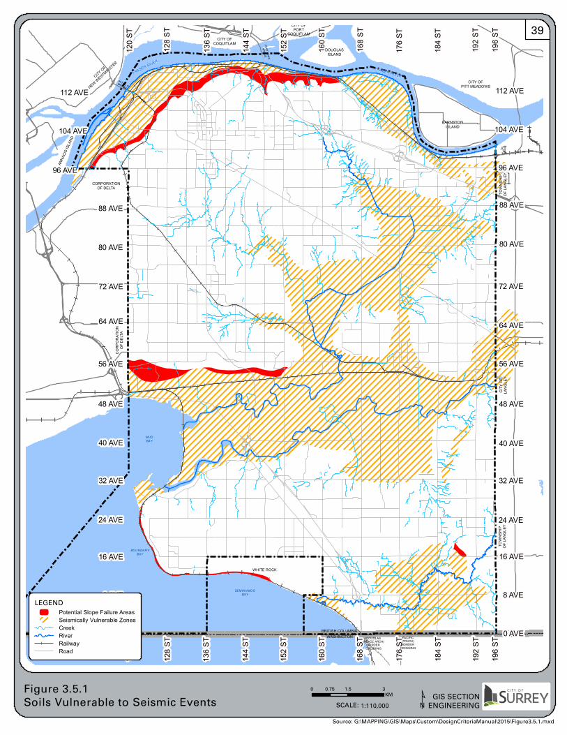
80 AVE
192 S
T
8 AVE
196 S
T
88 AVE
72 AVE
0 AVE
64 AVE
0 AVE
24 AVE
56 AVE
32 AVE
16 AVE
40 AVE
16 AVE
32 AVE19
6 ST
192 S
T
184 S
T
112 AVE
80 AVE
8 AVE
88 AVE
176 S
T
104 AVE
168 S
T
160 S
T
40 AVE
56 AVE
72 AVE15
2 ST
144 S
T
24 AVE
96 AVE12
8 ST
120 S
T
96 AVE
48 AVE
112 AVE
136 S
T
128 S
T
136 S
T
120 S
T
144 S
T
104 AVE
64 AVE
152 S
T
168 S
T
176 S
T48 AVE
160 S
T
184 S
T
BOUNDARYBAY
WHITE ROCK
PACIFIC(TRUCK)BORDER
CROSSING
BARNSTONISLAND
CITY OFPITT MEADOWS
DOUGLASISLAND
DOUGLAS(PEACE ARCH)
BORDERCROSSING
CITY OF
NEW WESTMINSTER
MUDBAY
CITY OFCOQUITLAM
FRASER RIVER
WASHINGTON
TOWN
SHIP
OF LA
NGLE
Y
C H A N N E L
CORPORATIONOF DELTA
CORP
ORAT
ION
OF D
ELTA
SEMIAHMOOBAY
TOWN
SHIP
OF LA
NGLE
Y
ANNA
CIS IS
LAND
PATULLOBRIDGE
BRITISH COLUMBIA
FRASER RIVER
F R A SE R R
IVE R
PORT MANNBRIDGE
CITY OFPORT
COQUITLAM
CITY
OF
LANG
LEY
0 1.5 30.75KM
Figure 3.5.1Soils Vulnerable to Seismic Events
GIS SECTIONENGINEERINGSCALE: 1:110,000
LEGEND
Potential Slope Failure AreasSeismically Vulnerable ZonesCreekRiverRailwayRoad
¹Source: G:\MAPPING\GIS\Maps\Custom\DesignCriteriaManual\2015\Figure3.5.1.mxd
39
City of Surrey WATER DISTRIBUTION Section 3.0 Engineering Department SYSTEM Page 40 Design Criteria Manual January 2016 3.5.5 Connections to Structures
The Consultant will calculate the expected differential movement between pipe and structure and provide a design that will accommodate the movement.
3.5.6 Service Connections
Provide an offset and or loop in the Service Connection to accommodate movement up to 0.5m of the pipeline through the soil. Flexible connections will be required at all connections to structures.
3.6 Agricultural Water Distribution System
3.6.1 Domestic Normal Household Water Supply
3.6.1.1 Hydraulic Design
The Agricultural Water Distribution System shall be designed for servicing the ultimate density of population expected:
a. Allowing for 4 people per lot for lot areas less than 4 ha.
b. Allowing for 8 people per lot for lot areas greater than 4 ha.
c. Average daily demand (ADD) = 750 l/capita/d.
d. Maximum Day Demand (MDD) = 1,500 l/capita/d .
e. Peak Hour Demand (PHD) = 3,000 l/capita/d .
f. No allowance for off‐site fire hydrant or on‐site fire services.
g. Minimum residual hydraulic head at ground level = 28m.
h. Single feed line (with only one source supply/node) shall not exceed 1200m.
City of Surrey WATER DISTRIBUTION Section 3.0 Engineering Department SYSTEM Page 41 Design Criteria Manual January 2016 3.6.1.2 Service Connection
Service Connections shall be 19mm or 25mm in diameter and disconnected from any alternate supply such as groundwater wells or surface water creeks or ditches. The Service Connection shall include a meter at property line, as per City’s Water Meter Design Criteria Manual and Supplementary Specifications, and backflow preventers as per City’s Cross Connection Control Standards and Specifications.
3.6.2 Domestic Non‐Household Water Supply
The Consultant will include both the household and non‐household water consumption in the calculation of Qdesign for the watermain evaluation. All non‐household water service shall have:
a. Separate water Service Connection;
b. Meter at property line;
c. Maximum size 50mm unless the non‐domestic water consumption is included in the Design Flow calculation, and used in the water main sizing; and
d. Pressure sustaining valve (PSV) will be installed within City’s road allowance. The pressure setting will trigger the shutting off the non‐domestic service when the pressure at the City water main drops below a pre‐set value, which will ensure that water pressure at domestic services exceeds 35m. The pressure setting of the PSV will be provided by the Engineer at each occurrence.
3.6.3 Water System Design
Water mains within the road right‐of‐way in agricultural areas shall be designed using the following criteria:
a. Main will be 100mm or 150mm nominal diameter;
b. Pipe material to be HDPE DR9;
c. Gate valves to be spaced less than 400m apart and no more than 20 services impacted by a valve closure; and
d. Air valves may be required to prevent potential floating as a result of air entrapment within a pipe, and their spacing will be appropriately designed.
SECTION 4
Sanitary Sewer System
City of Surrey SANITARY SEWER Section 4.0 Engineering Department SYSTEM Page 42 Design Criteria Manual January 2016 4 SANITARY SEWER SYSTEM
4.1 Sewage Flow Generation
4.1.1 Sewage Design Flows
For system analysis, the following formula shall be used to calculate the sewage design flows:
a. Average Dry Weather Flow(ADWF) – 350 L/capita/day x equivalent population.
b. Peak Dry Weather Flow(PDWF) – ADWF x Peaking Factor.
c. Peak Wet Weather Flow(PWWF) – ADWF x Peaking Factor + Inflow &Infiltration
For system analysis of minimum velocities, both ADWF and PWWF shall be used. For system analysis with respect to pipe capacity, the PWWF shall be deemed the Q design. Sewage flow computation should be presented in the format similar to Table 4.1.1.
4.1.2 Population Estimates and Equivalents:
The total design sewage flow [Q design] will be based on the ultimate saturation population densities and land‐use designations, in accordance with the OCP and related NCP, for the subject catchment area. Sanitary sewers will be sized to convey the calculated sewage flows, including infiltration and inflow. Sewage flows for residential areas shall be estimated using the population estimates, by housing type and area, including provision for secondary suites and coach houses, as provided in Section 2.3 of this Manual. Sewage flows for commercial and industrial areas will be estimated using the “population equivalents” estimates derived by using the Gross Density / Equivalent Population Factor, by zoning designation, as discussed in Section 2.3 of this Manual, with exception to the following special uses:
a. Hospitals – use 900 L/bed/day; and
b. Nursing and Rest Homes – use 450 L/bed/day.
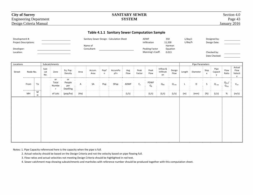
City of Surrey SANITARY SEWER Section 4.0 Engineering Department SYSTEM Page 43 Design Criteria Manual January 2016
Table 4.1.1 Sanitary Sewer Computation Sample
Development #: Sanitary Sewer Design ‐ Calculation Sheet ADWF 350 L/day/c Designed by:
Project Descriptions: Infiltration 11,200 L/day/h Design Date:
Developer: Name of Consultant: Peaking Factor
Harmon Equation
Location: Manning's Coeff. 0.013 Checked by:
Date Checked:
Locations Subcatchments Pipe Parameters
Street Node No. Sub‐cat No.
Zone Eq. Pop. Density
Area Accum. Area
Popl'n
AccumPopl'n
Avg Flow
Peak Factor
Peak Flow
Inflow & Infiltrati
on
Design Flow
Length Diameter Slope
Pipe Capacit
y
Flow Ratio
Actual Flow Velocit
y
From To
or Total Numbe
r
or People per
Dwelling
A SA Pop SPop ADWF Fp PDWF Qp
QI&I Q des L D S Q cap Qdes/Qcap
Vact
MH
MH
of Lots (pop/ha) (Ha)
(L/s)
(L/s) (L/s) (L/s) (m) (mm) (%) (L/s) % (m/s)
Notes: 1. Pipe Capacity referenced here is the capacity when the pipe is full.
2. Actual velocity should be based on the Design Criteria and not the velocity based on pipe flowing full.
3. Flow ratios and actual velocities not meeting Design Criteria should be highlighted in red text.
4. Sewer catchment map showing subcatchments and manholes with reference number should be produced together with this computation sheet.
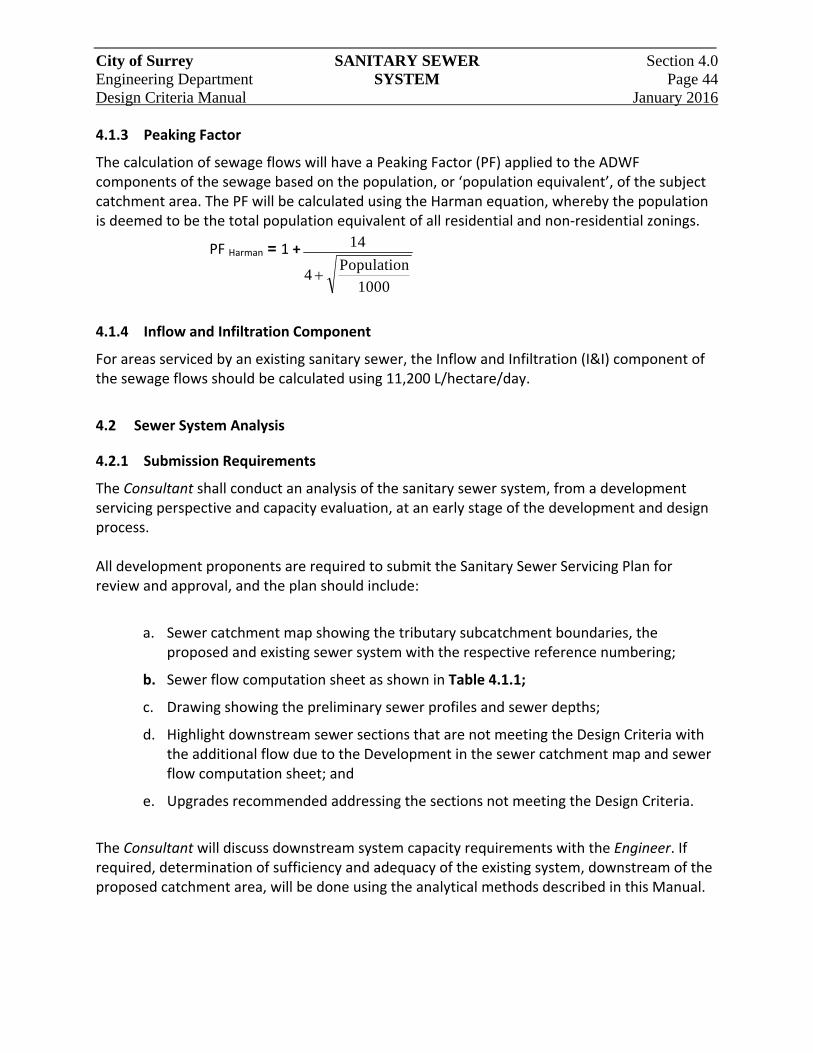
City of Surrey SANITARY SEWER Section 4.0 Engineering Department SYSTEM Page 44 Design Criteria Manual January 2016 4.1.3 Peaking Factor
The calculation of sewage flows will have a Peaking Factor (PF) applied to the ADWF components of the sewage based on the population, or ‘population equivalent’, of the subject catchment area. The PF will be calculated using the Harman equation, whereby the population is deemed to be the total population equivalent of all residential and non‐residential zonings.
PF Harman = 1 + 14
41000
Population
4.1.4 Inflow and Infiltration Component
For areas serviced by an existing sanitary sewer, the Inflow and Infiltration (I&I) component of the sewage flows should be calculated using 11,200 L/hectare/day.
4.2 Sewer System Analysis
4.2.1 Submission Requirements
The Consultant shall conduct an analysis of the sanitary sewer system, from a development servicing perspective and capacity evaluation, at an early stage of the development and design process. All development proponents are required to submit the Sanitary Sewer Servicing Plan for review and approval, and the plan should include:
a. Sewer catchment map showing the tributary subcatchment boundaries, the proposed and existing sewer system with the respective reference numbering;
b. Sewer flow computation sheet as shown in Table 4.1.1;
c. Drawing showing the preliminary sewer profiles and sewer depths;
d. Highlight downstream sewer sections that are not meeting the Design Criteria with the additional flow due to the Development in the sewer catchment map and sewer flow computation sheet; and
e. Upgrades recommended addressing the sections not meeting the Design Criteria.
The Consultant will discuss downstream system capacity requirements with the Engineer. If required, determination of sufficiency and adequacy of the existing system, downstream of the proposed catchment area, will be done using the analytical methods described in this Manual.
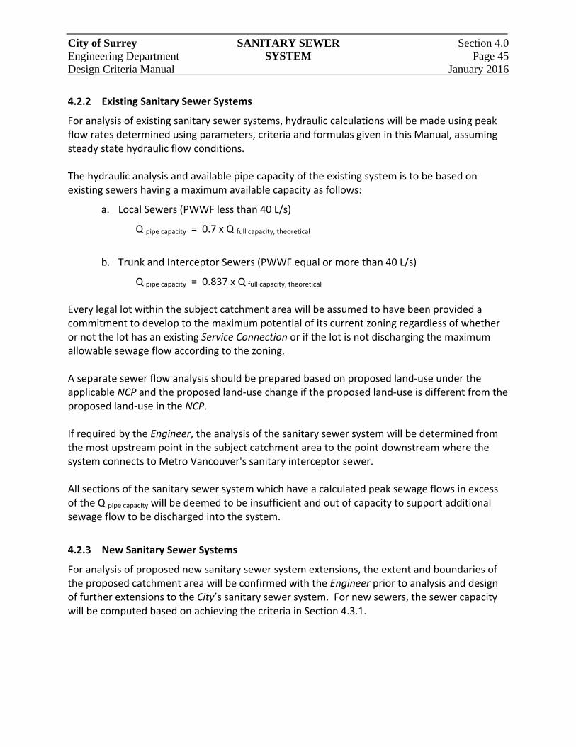
City of Surrey SANITARY SEWER Section 4.0 Engineering Department SYSTEM Page 45 Design Criteria Manual January 2016
4.2.2 Existing Sanitary Sewer Systems
For analysis of existing sanitary sewer systems, hydraulic calculations will be made using peak flow rates determined using parameters, criteria and formulas given in this Manual, assuming steady state hydraulic flow conditions. The hydraulic analysis and available pipe capacity of the existing system is to be based on existing sewers having a maximum available capacity as follows:
a. Local Sewers (PWWF less than 40 L/s)
Q pipe capacity = 0.7 x Q full capacity, theoretical
b. Trunk and Interceptor Sewers (PWWF equal or more than 40 L/s)
Q pipe capacity = 0.837 x Q full capacity, theoretical Every legal lot within the subject catchment area will be assumed to have been provided a commitment to develop to the maximum potential of its current zoning regardless of whether or not the lot has an existing Service Connection or if the lot is not discharging the maximum allowable sewage flow according to the zoning. A separate sewer flow analysis should be prepared based on proposed land‐use under the applicable NCP and the proposed land‐use change if the proposed land‐use is different from the proposed land‐use in the NCP. If required by the Engineer, the analysis of the sanitary sewer system will be determined from the most upstream point in the subject catchment area to the point downstream where the system connects to Metro Vancouver's sanitary interceptor sewer. All sections of the sanitary sewer system which have a calculated peak sewage flows in excess of the Q pipe capacity will be deemed to be insufficient and out of capacity to support additional sewage flow to be discharged into the system.
4.2.3 New Sanitary Sewer Systems
For analysis of proposed new sanitary sewer system extensions, the extent and boundaries of the proposed catchment area will be confirmed with the Engineer prior to analysis and design of further extensions to the City’s sanitary sewer system. For new sewers, the sewer capacity will be computed based on achieving the criteria in Section 4.3.1.
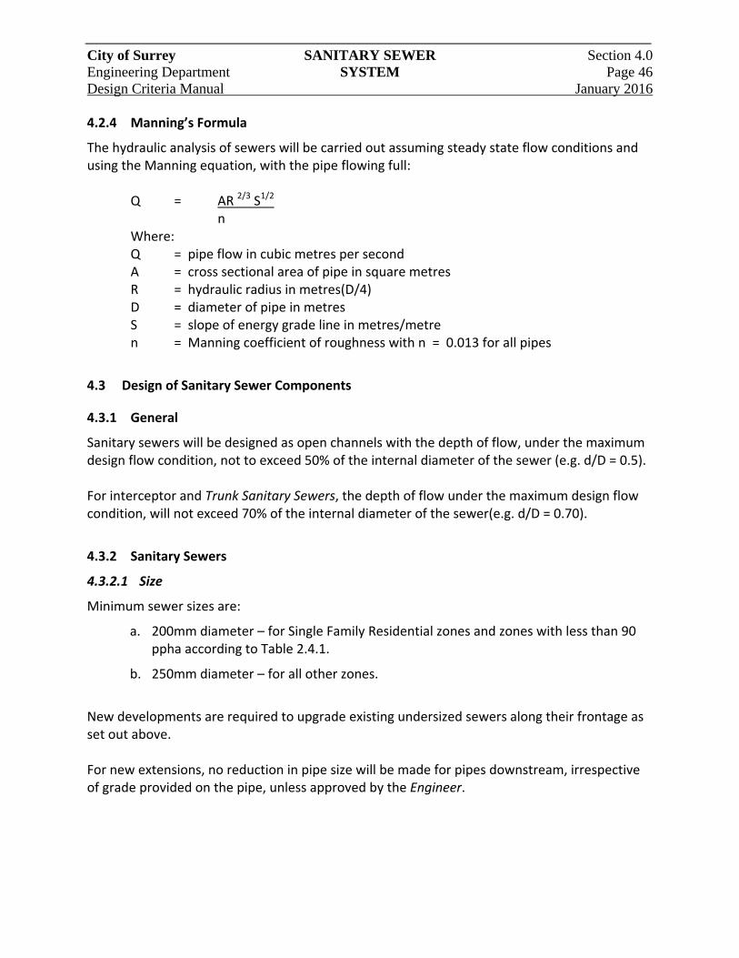
City of Surrey SANITARY SEWER Section 4.0 Engineering Department SYSTEM Page 46 Design Criteria Manual January 2016 4.2.4 Manning’s Formula
The hydraulic analysis of sewers will be carried out assuming steady state flow conditions and using the Manning equation, with the pipe flowing full:
Q = AR 2/3 S1/2 n Where: Q = pipe flow in cubic metres per second A = cross sectional area of pipe in square metres R = hydraulic radius in metres(D/4) D = diameter of pipe in metres S = slope of energy grade line in metres/metre n = Manning coefficient of roughness with n = 0.013 for all pipes
4.3 Design of Sanitary Sewer Components
4.3.1 General
Sanitary sewers will be designed as open channels with the depth of flow, under the maximum design flow condition, not to exceed 50% of the internal diameter of the sewer (e.g. d/D = 0.5). For interceptor and Trunk Sanitary Sewers, the depth of flow under the maximum design flow condition, will not exceed 70% of the internal diameter of the sewer(e.g. d/D = 0.70).
4.3.2 Sanitary Sewers
4.3.2.1 Size
Minimum sewer sizes are:
a. 200mm diameter – for Single Family Residential zones and zones with less than 90 ppha according to Table 2.4.1.
b. 250mm diameter – for all other zones.
New developments are required to upgrade existing undersized sewers along their frontage as set out above. For new extensions, no reduction in pipe size will be made for pipes downstream, irrespective of grade provided on the pipe, unless approved by the Engineer.
City of Surrey SANITARY SEWER Section 4.0 Engineering Department SYSTEM Page 47 Design Criteria Manual January 2016 4.3.2.2 Location
Sewers will be located, as shown on the Standard Drawings, in a Highway. All non‐standard utility off‐sets are to be supported by a typical cross‐section showing all utilities and the ultimate road section. Where not technically feasible, as determined by the Engineer, sewers may be approved in side yard and rear yard rights‐of‐way if:
a. The right‐of‐way minimum width meets the requirements set out in Section 2.5.8;
b. The right‐of‐way is capable of supporting the intended maintenance vehicles in all weather conditions;
c. Within the rights‐of‐way, there are no Service Connections or manholes and the sewer alignment must be straight; and
d. The right‐of‐way includes an all‐weather road surface for service or maintenance.
All weather vehicular access must be provided to all manholes, inlet structures, inspection chambers and flow control structures. 4.3.2.3 Depth
Sewer depth will be sufficient to provide appropriate gravity Service Connections to all properties tributary to the sewer. Unless approved by the Engineer, sewers will be installed at a nominal depth between 2.0m and 3.5m, from finished ground surface to pipe invert. Pipe cover less than 1.5m but more than 1.0m above the outside crown of the pipe may be permitted if the location of the sanitary sewer is outside the roadway and driveways. Unless approved by the Engineer, no Service Connections will be installed on sewers greater than 4.5m depth, and if permitted then a second main at maximum depth of 3.5m must be installed to facilitate Service Connections. Where a new sewer will service existing buildings and existing vacant properties, the crown of the sewer will be at least 1.0m below the basement elevations of the lots to be serviced.
City of Surrey SANITARY SEWER Section 4.0 Engineering Department SYSTEM Page 48 Design Criteria Manual January 2016 4.3.2.4 Curvilinear Sewers
Curvilinear sewers are only permitted under special circumstances and must be approved by the Engineer. When permitted, pipes between two consecutive manholes may be installed on a defined curve, provided that the maximum joint deflection does not exceed 1/2 the deflection recommended by the pipe manufacturer. Only one vertical or one horizontal defined curve is permitted between any two manholes. Curvilinear sewer designs will include proposed elevations at 5m stations for vertical curves and sufficient data for setting out of horizontal curves and detailing as‐built construction record information. PVC pipes shall not be bent (between the pipe joint ends) to form curves. Manufactured long bends or PVC high deflection stops coupling shall be used to achieve curves, when curvilinear sewers are approved by the Engineer. 4.3.2.5 Pipe Grades
Sewers are to be designed with a constant grade. Pipes with grades at 15 % or greater must have an anchoring system approved by the Engineer, and designed with special attention to scour velocities and potential damage to the pipe structure. Proposed pipe protection systems to prevent pipe invert damage must be approved by the Engineer. The upstream most sewers may require steeper grade to ensure a self‐cleansing velocity under partial flow conditions. The following design alternatives are acceptable:
a. The Terminal section of sanitary sewer, servicing 6 or less house Service Connections, will have a minimum grade of 1.0 %.
b. A sanitary sewer, servicing the 7th to 12th house Service Connections, will have a grade of 0.6 % or greater.
c. A sanitary sewer, servicing the 13th house Service Connection(or more), will have a grade of 0.5 % or greater.
4.3.2.6 Velocities
Pipe grades less than 0.5 % may only be used when approved by the Engineer when the flow, equal to 0.7 x Peak Dry Weather Flow, from full development upstream attains a minimum velocity of 0.6 m/s once every twenty four hours based on partial (not full) pipe flow hydraulics. Where the sanitary sewer pipe grade is such that the velocity of flow is in excess of 5 m/s, the system design will include measures to prevent problems related to scour, erosion and pipe movement.

City of Surrey SANITARY SEWER Section 4.0 Engineering Department SYSTEM Page 49 Design Criteria Manual January 2016 4.3.2.7 Connections to Metro Vancouver
Tie‐ins to Metro Vancouver trunk interceptors must have some form of odour control. Odour control will be reviewed and approved by Metro Vancouver and the Engineer.
4.3.3 Aerial Pipe Bridges and Inverted Siphons
Proposed exposed bridge‐type crossings of sanitary sewers or inverted siphons must be approved by the Engineer prior to proceeding with the design. Inverted siphons are to be provided with pigging and flushing ports. A blowdown chamber is to be provided at each of all low points.
4.3.4 Manhole Structures
4.3.4.1 Location
Manholes are required every 150m of sewer mains (or every 300m if mid‐block clean‐outs are provided) and under the following conditions:
a. At the top end of all Terminal Sewers;
b. Every change of pipe size;
c. Every change of line or grade that exceeds 1/2 the maximum joint deflection recommended by the manufacturer, or where the radius of an approved curvilinear sewer alignment is less than 30m;
d. All sewer confluences and junctions, (except those with interceptor sewers);
e. Sump manhole to be provided immediately upstream of any line feeding to a pump station, siphon or Force Main system;
f. At Service Connection tie‐ins to mains where the Service Connection size is greater than ½ the diameter of the main; and
g. At property line where the Service Connection is 200mm diameter or larger.
Temporary cleanouts are permitted where a future extension of the sewer will provide a manhole at an appropriate spacing. Clean‐outs are not permitted at the Terminal ends of the system. Mid‐block clean‐outs with the foot‐bend pointing uphill are permitted between two manhole structures. Manholes within road right‐of‐ways will be located within the travel Lanes or center median as appropriate, and not closer than 1.5m from the curb. Manhole frames and covers will not be located within a sidewalk unless approved by the Engineer. Offset manholes in the two systems may be considered under some circumstances and must be approved by the Engineer.
July 11/16
City of Surrey SANITARY SEWER Section 4.0 Engineering Department SYSTEM Page 50 Design Criteria Manual January 2016 4.3.4.2 Drop Manhole Structures
Drop manholes, designed in accordance with the Standard Drawings, will only be used when a new incoming sewer cannot be steepened or where site conditions do not permit excavation to the base of an existing manhole. Drop manholes are not permitted for sewer mains 450mm and larger, and not permitted when the depth of the main is less than 3.5m. Drop manholes shall be:
a. 1200mm diameter manholes with an inside drop for mains less than or equal to 300mm diameter; or
b. 1500mm diameter manholes with an inside drop for mains larger than 300mm.
Outside drop structures, complete with upstream cleanouts for maintenance may be approved by the Engineer. A straight through ramp drop may be approved by the Engineer. 4.3.4.3 Through Manhole Structures
The crown elevations of sewers entering a manhole will not be lower than the crown elevation of the outlet sewer. No drop in invert is required for a through manhole where the sewer mains are of the same size. A 30mm drop in invert for alignment deflections up to 45 degrees and a 60mm drop in invert for alignment deflections from 45 degrees to 90 degrees will be provided.
4.3.5 Service Connections
Each lot will have:
a. A gravity connection to the frontage sewer; or
b. A gravity connection to the sewer in an open Lane, walkway or service corridor with an access road.
Where the above connection is not possible and when approved by the Engineer, each lot may have:
a. A pumped connection to a frontage sewer, provided: a gravity connection is not feasible; a restrictive covenant is registered on the lot; or
b. A gravity connection through a registered private easement over only one lot to a suitable sewer, in addition to a dedicated connection to a frontage sewer the serviced lot for possible future pumped connection.
4.3.5.1 Size
The size of a Service Connection will be selected to accommodate the PWWF generated on the property being served and shall be:
City of Surrey SANITARY SEWER Section 4.0 Engineering Department SYSTEM Page 51 Design Criteria Manual January 2016
a. A minimum 100mm diameter for all single family residential lots; and
b. A minimum 150mm for all other zonings.
A separate Service Connection will be provided to each legal lot fronting a City gravity sanitary sewer. If there is more than one building structure on a legal lot and there is a potential for future subdivision, each building unit will require an independent Service Connection. The Consultant is to review these circumstances with the Engineer. Duplex residential premises will be provided with independent Service Connections for each unit.
4.3.5.2 Location, Depth and Grade
Service Connections shall be installed at a minimum slope of 2.0% between the crown of the sewer main and the inspection chamber at property line, as shown on the Standard Drawings. The invert of the Service Connection inspection chamber (IC) must be a minimum 1.2 m below the finished ground elevation at the inspection chamber. For undeveloped lots, the depth shall provide sufficient grade to a building structure which could be located at a front‐yard setback of 7.5m. For Service Connections to existing Trunk or interceptor sewers, the invert of the Service Connection inspection chamber will be a minimum of 1.0m above the crown of the Trunk or interceptor sewer. If the hydraulic elevation of any potential surcharge in the Trunk or interceptor sewer is known, the invert of the inspection chamber on the Service Connection must be at least 300mm above the surcharge elevation. Where a building structure exists on a legal lot, Service Connections shall be installed at the location acceptable to the property owner. The Service Connection is to be extended 2.0m into the property, if approved by the property owner. 4.3.5.3 Tie‐in
Tie‐ins will be in accordance with the Standard Drawings. A Service Connection to a manhole will have its invert at the crown elevation of the highest sewer in the manhole, and the connection will discharge in the same direction as that of the sewer main.
City of Surrey SANITARY SEWER Section 4.0 Engineering Department SYSTEM Page 52 Design Criteria Manual January 2016 4.3.6 Special Connections
Direct connections to a Metro Vancouver Trunk or interceptor sewers may be permitted by Metro Vancouver and the Engineer. When permitted, connections will comply with the criteria and details stipulated by the Metro Vancouver. Service Connections to a Metro Vancouver sewer will require a p‐trap or some other means to control odour into the service lateral.
4.3.7 Odour Mitigation
The Engineer may require “p” traps to be installed to address existing or anticipated odour concerns. In addition, the Engineer may require odour mitigation facilities to be installed.
4.4 Design of Pump Stations and Force Mains
Detailed criteria specific requirements and design for pump station and Force Main will be as per instructions provided by the Engineer, prior to design of the facilities. Good engineering design practice will be used in the design of sanitary sewage pump stations and Force Mains. It is recommended that the Consultant refers to the City’s "Guideline for the Design & Construction of Sanitary Sewage Pumping Stations." Prior to commencing detailed design of a pump station, the Consultant will confirm the design catchment areas, design flows and the proposed location of the pumping station facility with the Engineer. The Consultant will submit a preliminary design report that addresses the requirements given in this Manual and the "Guideline for the Design & Construction of Sanitary Sewage Pumping Stations" for approval by the Engineer, prior to commencing detailed design. The pump station and/or Force Main are to be designed for the defined tributary catchment area, with design flows calculated for: short term, intermediate future and ultimate (development at saturation) stages.
4.5 Low Pressure Sewerage System
4.5.1 General
The City may consider low pressure sanitary sewer systems for areas which are beyond the reaches of the City gravity sewer system and not large enough to provide economic justification for a community sewage pump station, or where soil conditions or topography are not suitable for a gravity sewer system. A low pressure sanitary sewer system consists of on‐site, privately owned and operated sewage pump unit with discharge pipes connected to either: an inspection chamber at property; or City‐owned gravity sewer; or a City‐owned and operated low pressure sewage Force Main. Systems in which private pump units discharge into a public gravity sewer or Force Main from a public community sewage pump station are not classified as low pressure sanitary sewer systems. Where specifically indicated herein, some of the items included in this Low Pressure Sewerage System section are applicable to such other pumped systems.
City of Surrey SANITARY SEWER Section 4.0 Engineering Department SYSTEM Page 53 Design Criteria Manual January 2016 Pump unit details design and all ancillary components design within the private property shall be certified by the Consultant, and the intent of this Section is to provide design guidelines to the Consultant.
4.5.2 Restrictive Covenant and Sanitary Right‐of‐Way
The land title for each legal lot served by a private pump unit located on the subject lot shall include a restrictive covenant, filed by the property owner, requiring the property owner to undertake in perpetuity operation, maintenance and renewal of the pump unit and Service Connection to the City Force Main, including the section of Service Connection within the road right‐of‐way. The required format of the restrictive covenant will be provided by the City at the Preliminary Design stage. A sanitary right‐of‐way will be registered for the valve chamber, at property line, to allow City to access and operate the chamber if necessary. The ownership and the responsibility for the operation and maintenance of the chamber is that of the property owner. Excavation of the portion of connection pipe located on public property or right‐of‐way requires permit from the City.
4.5.3 Codes and Standards
Low pressure sewer systems and the components thereof will be designed and constructed in conformance with the following codes and standards:
a. Canadian and British Columbia Electrical Code;
b. British Columbia Public Health Act and Sewage System Regulation;
c. British Columbia Plumbing Code;
d. Greater Vancouver Regional District Sewer Use By‐law;
e. Master Municipal Construction Documents and Supplementary Specifications;
f. Surrey Plumbing By‐law, No. 6569;
g. Surrey Connection of Electrical Services By‐law, No.4726; and
h. Workers Compensation Board Regulations
City of Surrey SANITARY SEWER Section 4.0 Engineering Department SYSTEM Page 54 Design Criteria Manual January 2016 4.5.4 System Layout
The preliminary layout of a proposed low pressure system should be approved by the Engineer before detailed design proceeds. 4.5.4.1 Preliminary Design
The following information is required as part of the preliminary design submission:
a. Plan of the entire area to be served by the proposed system, including adjacent areas currently and potentially served by gravity sewers and community sewage pump stations;
b. Topographic plan;
c. Report on soil conditions;
d. Preliminary layout;
e. Area development sequence and timetable; and
f. Pump unit power requirements.
4.5.4.2 Design Development
At the detailed design stage, the following information will be submitted to the Engineer for review and approval:
a. HGL for the City Force Main;
b. Location, elevation and of each pump unit, valve chamber and Service Connection;
c. Pump head and capacity requirements, plus recommended manufacturer and model, pump curve and power requirements;
d. Pump unit diameter, depth, operating levels and configuration (simplex or duplex);
e. Location and direction of flow of each lateral, branch and main, plus details of the system discharge point. Sewer system should be designed to minimize length of runs, avoid abrupt changes in direction;
f. Location and elevation of system high points, where high points are unavoidable;
g. Qualifications of supplier of pump unit package as indicated under Pump Unit General Requirements; and
h. Sample of Operation and Maintenance document to be provided with pump unit.

City of Surrey SANITARY SEWER Section 4.0 Engineering Department SYSTEM Page 55 Design Criteria Manual January 2016 4.5.5 System Hydraulic Design
System design will include complete hydraulic data for each section of the City Force Main including flows, heads, velocities and maximum retention times. Submission of this information will include a table showing all of the data for each anticipated stage of the system development.
4.5.6 Design Flows and Hydraulics
Design flows for sizing pressure sewers, including Service Connections and City Force Mains, will be determined on the basis of the velocity and head criteria as summarized in these guidelines, and using one of the following procedures, depending upon the land‐use. 4.5.6.1 Single Family Residential Areas
For single family residential areas, estimated the number of pump units operating simultaneously is provided in Table 4.5.1. For calculating design flows, the minimum design flow per pump unit, or Service Connection, is 0.7 L/s; with a rate of 2.1 L/s to be used for the most upstream connection on the Force Main.
Table 4.5.1:Low Pressure Pumps Operating Simultaneously
Number of Single Family Residential Pumps Connected
Number of Pumps Operating Simultaneously
1 1
2 to 3 2
4 to 9 3
10 to 18 4
19 to 30 5
31 to 50 6
51 to 80 7
81 to 113 8
114 to 149 9
City of Surrey SANITARY SEWER Section 4.0 Engineering Department SYSTEM Page 56 Design Criteria Manual January 2016 4.5.6.2 Multi‐Family, Non‐Residential and Mixed Areas
The following formula will be used for any development in which pump capacities exceed those for single‐family residences. For the upstream end of the system, where there are only one or two connections, assume the connected pumps are operating.
Q design = CP + F Where: Q = Design flow in L/s C = Coefficient based on land‐use and peaking factor; standard value: 0.008 P = Population or equivalent F = Factor based on minimum flows, standard value: 2.10
4.5.6.3 Hydraulic Calculations
Criteria for Hydraulic design calculations include the following:
a. Pipe flow formula: Hazen Williams, with friction coefficient C=130;
b. Minimum velocity: V = 0.6 m/s; and
c. Maximum operating head (total dynamic head, TDH): compatible with pumps and not exceeding 35m (343 kPa) unless otherwise approved by the Engineer.
System test pressures will be 2.0 times the maximum operating head and not less than 700 kPa.
4.5.7 Pipe
Minimum pipe sizes are as follows:
a. From pump unit to City low pressure Force Main: 38mm ID; and
b. City low pressure sewage Force Main: 50mm ID.
Low pressure Force Mains shall be installed at a minimum depth of cover of 1.0m when located within the City road right‐of‐way and 0.75m on private property. The maximum depth shall not exceed 3.0m unless approved by the Engineer. All joints on the Force Main shall be compatible with pipe material and fittings, and complete with appropriate thrust restraints in accordance with the Supplementary Specifications. The segment of Force Main between pump unit and City Force Main will include 150mm wide Detectable Warning Tape placed above the Force Main at a depth of 150mm below the ground surface.
City of Surrey SANITARY SEWER Section 4.0 Engineering Department SYSTEM Page 57 Design Criteria Manual January 2016 4.5.8 Cleanout Manholes
Cleanout manholes are required on low pressure Force Main sat ends, junctions, low points,
changes of direction exceeding 22.5 and at maximum 100m spacing. Details of the cleanouts are shown on the Standard Drawings.
4.5.9 Air Valves
Sewage air release valves are required at system high points and major changes in grade (10% or greater). Details of air valve assemblies are shown on the Standard Drawings.
4.5.10 Discharge
Location and detail of low pressure sewer Force Main discharge will be subject to the Engineer’s approval. Discharge will be into a manhole and will include fittings to make the discharge submerged, while the fittings will be removable to provide for flushing.
4.5.11 Service Connections
Service Connections to the City Force Main will include integral wye fittings oriented in the direction of flow and a gate valve at the main line to isolate the Service Connection. Each Service Connection will include a valve chamber located on private property at the property line. Details of the valve chamber and fittings are shown on the Standard Drawings. Check valves will be epoxy‐coated cast iron, full‐ported, wye body ball check valves.
4.5.12 Pump Unit Requirements
Pumps for low pressure systems will be submersible grinder pumps capable of discharging the design flow at the maximum operating head. Pump design flow will be the greater of PDWF or the flow required to achieve the minimum flow velocity. General requirements include the following:
a. Pump unit package design, including the Service Connection, shall be sealed by the Consultant;
b. All pump and control equipment will be certified by CSA or an equivalent certification agency approved by the Engineer;
c. Pump unit specifications are subject to approval by the Engineer;
d. A plumbing and electrical permit is required for a pump unit;
e. Duplex (two pump) units are required for multi‐family and non‐residential properties;
City of Surrey SANITARY SEWER Section 4.0 Engineering Department SYSTEM Page 58 Design Criteria Manual January 2016
f. The pump unit will be installed outside of the building in a location convenient for maintenance. The control/alarm panel will be located in close proximity to the chamber either outside or inside of the building;
g. Detailed, concise operating and maintenance instructions will be submitted to the owner of each pump unit package. A summary of these instructions will be taped to the inside of the control panel door; and
h. Pump unit suppliers will have documented experience and ability in design, supply and servicing of pump unit packages including pump(s), chamber, piping and controls.
Grinder pumps will be either centrifugal or semi‐positive displacement pumps. The grinder assembly will consist of hardened stainless steel components designed to grind sewage solids into fine particles, which pass easily through 32mm diameter pump and piping. The electrical and control cable(s) from the pump shall have a minimum 30m whip length. Pump units discharging through 100mm diameter, or larger, Service Connections into 150mm diameter, or larger, low pressure Force Mains or gravity sewers may be solids‐handling submersible centrifugal pumps. Pump curves will be “steep” within the design operating range, where total head is below the maximum operating head, such that the reduction of capacity with increasing head does not exceed 0.03 L/s/m. Pumps will be manufactured using durable, non‐corrosive metallic components, and will be supplied with a warranty effective for at least two (2) years after startup.
4.5.13 Pump Chamber Details
Criteria for pump chamber design will include the following:
a. Material and construction: Fibreglass reinforced polyester (FRP) or high density polyethylene (HDPE) with smooth interior, bottom shaped to avoid solids build‐up, walls and bottom of sufficient thickness or with exterior corrugations to withstand soil pressure, and base to include flange for concrete collar to prevent flotation;
b. Chamber lid and connections (inlet, discharge, ventilation and electrical) will be factory installed and watertight; the lid will be reinforced FRP or galvanized steel and provide access to full diameter of tank;
c. A minimum chamber diameter of 750mm diameter is required to provide for convenient operating and maintenance access and required storage volumes;
d. Depth to accommodate inlet and discharge pipe elevations and to provide sufficient operating and storage volumes;
City of Surrey SANITARY SEWER Section 4.0 Engineering Department SYSTEM Page 59 Design Criteria Manual January 2016
e. Chamber volume between pump on and off levels to be based on pump cycle times between 5 and 30 minutes, with preference for normal operating depth ranging from 150mm to 200mm. A typical operating volume for a single family residential unit is 200 L; and
f. Chamber volume for emergency storage (above normal pump on level) will be based on minimum 6 hours storage at ADWF . Subject to approval by the Engineer, emergency storage may be provided in a separate chamber, or standby power may be provided in lieu of emergency storage.
4.5.14 Piping Details
Piping design criteria for the inside of the pump chamber will include the following:
a. Pump chamber piping will be designed to accommodate easy pump removal and replacement. Unless an approved equivalent system is provided, pump chambers 1050mm in diameter, or greater, and also those chambers with a depth of 1.8m, or greater, will include a pump lift out coupling and slide rail system;
b. Pump discharge piping will include full ported check valve and ball valve. Where a slide rail system is not provided, a union will be installed before the two valves, with the union, a check valve and a ball valve installed in that sequence in the direction of flow; and
c. An anti‐siphon valve is required where a pump is located higher than any part of the low pressure system.
4.5.15 Pump Chamber Ventilation
Each pump chamber will include a vent pipe with a diameter of at least 75mm in diameter, or one diameter smaller than the size of the largest inlet pipe, whichever is larger, up to a maximum vent size of 150mm diameter, and installed in accordance with the BC Plumbing Code and Surrey Plumbing By‐law. Unless otherwise approved by the Engineer, or plumbing inspector, the vent discharge will be installed with a minimum of 450mm cover below ground level, at a positive slope draining towards the pump chamber, to the building wall. At the building exterior, the vent should extend at least 1.8m above ground, anchored to the building, and not within 3.0m of doors or windows. If approved by the Engineer, or plumbing inspector, the vent discharge may be located either on the building exterior wall or attached to a post in a secure location if the pump chamber is greater than 15m away from the building.

City of Surrey SANITARY SEWER Section 4.0 Engineering Department SYSTEM Page 60 Design Criteria Manual January 2016 4.5.16 Electrical
All materials and installation will comply with the B.C. Electrical Code Regulation and City requirements. Power supply will be from the building served by the pump unit. The following nominal service voltages will be acceptable:
a. For residential installations: 120/208 V or 120/240 V, single‐phase; and
b. For industrial/commercial installations: as above, or 120/208 V or 347/600 V, three‐phase.
Wiring from the building to the pump chamber will be underground and continuous, with no splices, whereby the installed length of wiring (horizontal plus vertical grade difference) between the control cabinet pump shall be less than the minimum whip length required for the pump. Where a building electrical system includes emergency standby power, the pump unit power supply shall be connected to the emergency power.
4.5.17 Pump Chamber Classification
Pump chambers for single‐family and duplex residential service are not considered to be “hazardous locations” for electrical code purposes. Pump chambers for multi‐family and non‐residential service are considered as Hazardous, Class I locations. Material and installation requirements for these locations are further classified as either Zone 1 or Zone 2, depending upon the standard of ventilation, as follows:
a. Zone 1: No mechanical (forced air) ventilation
Motors must be “explosion‐proof”;
Motors must have over‐temperature protection; and
Float switches must have “intrinsic safe barriers”.
b. Zone 2:“Adequate” (forced air) ventilation:
3‐phase submersible motors must remain fully submerged;
Single‐phase submersible motors must remain fully submerged if they have no spark‐producing devices. If they have spark‐producing devices, these motors must be “explosion proof”; and
Float switches must have “intrinsic safe barriers”.
4.5.18 Controls
Pump controls will automatically start and stop the pump(s) and provide a high level alarm.
City of Surrey SANITARY SEWER Section 4.0 Engineering Department SYSTEM Page 61 Design Criteria Manual January 2016 Level switches will be either pressure switches, if approved by the Engineer, or float switches. Power and control wiring will be continuous from the pump unit and level switches to junction boxes located above grade on the exterior of the building. Where the pump chamber is classified as hazardous, a conduit seal will be provided between the junction box and the control cabinet. Subject to prior approval by the Engineer, or building inspector, the control cabinet will be installed in one of the following locations:
a. On an exterior building wall closest to the pump chamber;
b. Inside the building near an outside door which is close to the pump chamber; or
c. On a post adjacent to the pump chamber if the chamber is located 25m or more away from the building.
If located outdoors, the control cabinet will be lockable and weatherproof (EEMAC Type 3) and made from non‐corrosive materials. Junction boxes will be non‐corrosive Type 4X, or NEMA 4 painted steel enclosure. The control panel shall include the following features:
Control voltage limited to maximum 120 VAC;
“Power on” light;
Float switch indication lights;
Green “pump on” light;
Red “motor overload” light;
Manual reset of fault conditions;
High level alarm light (“red”) and buzzer;
Pump disconnect switch;
Motor starter;
Hand‐Off‐Auto (HOA) selector switch;
Control transformer, if required to suit control voltage;
Automatic alternator for multiple pump units;
Control Fuse;
Terminal Strip; and
Form “C” (SPDT) alarm contact, rated minimum 3A, 120 VAC, wired to a set of isolated Terminal blocks.
The alarm circuit will include an alarm light and signal/buzzer with a test /silence switch. If the control cabinet is mounted outside, the alarm light will be located outside and the alarm signal will be transmitted to an alarm box installed inside the building.
City of Surrey SANITARY SEWER Section 4.0 Engineering Department SYSTEM Page 62 Design Criteria Manual January 2016 In non‐residential and multi‐family installations, a remote alarm using telephone auto‐dialer or other suitable technology should be considered.
4.6 Sanitary Sewer Seismic Design Standards
4.6.1 Area
The areas where the seismic design standards apply are delineated on Figure 3.5.3. If the Consultant disagrees with the lateral displacement zones shown on the map, the Consultant will be responsible for conducting a detailed site investigation to demonstrate, to the satisfaction of the Engineer, that the site is not subject to liquefaction or landslide. The following design criteria must be used in areas subject to permanent ground deformation due to liquefaction or landslide. The Consultant will calculate and submit to the Engineer the expected differential horizontal and vertical movement and provide a design that will accommodate the movement.
4.6.2 Gravity Sewers – Class 1
Class 1 design criteria apply in areas subject to permanent ground deformation due to liquefaction or landslide, where there may potentially be severe sewer failure consequences. The proposed Class 1 criteria should be applied within these areas where the gravity sewer are installed:
a. Above a potable water pipeline;
b. Parallel to a potable water pipeline with less than 3.0m of separation;
c. Within 100m of an environmentally sensitive water body;
d. Within the recharge area for a potable water well or spring supply; and
e. In other locations where the failure consequences would be significant as required by the Engineer.
The sewer will be designed so that the joints will not separate, and that the pipe will experience ductile deformation to accommodate permanent ground deformation during an earthquake. The design will limit the flotation of the pipe. 4.6.2.1 Materials
Use of ductile iron, steel, or high‐density polyethylene pipe and fittings is required, and all materials shall comply with the Supplementary Specifications. Use of concrete pipe (either reinforced or un‐reinforced), PVC, and grey or cast iron pipe or fittings is not allowed.

City of Surrey SANITARY SEWER Section 4.0 Engineering Department SYSTEM Page 63 Design Criteria Manual January 2016 4.6.2.2 Joint Restraint
All pipeline, fittings and appurtenance joints will be restrained, so that they will not allow pullout when subjected to extension forces. The joint restraint system will be strong enough to resist loading developed by 50m of buried pipe being pulled through the ground (wrapped in polyethylene). 4.6.2.3 Pipe Wrapping
Pipe will be wrapped with 8 mill thickness polyethylene (a baggy), such as is commonly used for corrosion protection, to minimize soil‐pipe interaction. It is not the intent that this pipe wrapping will provide corrosion protection. 4.6.2.4 Pipe Flotation Control
If the pipeline is located within the liquefiable layer and is 500mm or greater in diameter, provision should be made to limit flotation, either by designing the pipe system for neutral buoyancy in liquefiable soils or positively holding down the pipe to keep it from floating under liquefaction conditions. Typically, any required flotation control is achieved by encasing the pipe in concrete in order to achieve the specified neutral buoyancy. Under most circumstances, it is acceptable to assume that the pipe is half‐full of sewage for the purposes of these calculations. 4.6.2.5 Manhole Flotation Control
Provision will be made to limit flotation, either by designing the manhole for neutral buoyancy in liquefiable soils or positively holding down the manhole to keep it from floating for manholes with one or more pipes of 500mm or greater diameter entering the manhole. Typically any required flotation control is achieved by thickening the concrete base slab order to achieve the specified neutral buoyancy.

City of Surrey SANITARY SEWER Section 4.0 Engineering Department SYSTEM Page 64 Design Criteria Manual January 2016 4.6.2.6 Connections to Manholes and Structures
The Consultant will calculate the expected differential movement between the pipe and structure, and provide a design that will accommodate the movement to the satisfaction of the Engineer for manholes with pipes of 500mm, or greater, diameter entering the chamber. Typically this would be achieved by installing two mechanical couplings or flexible joints in the sewer pipe. One would be located close to the outside face of the manhole barrel and one would be located a short distance away, ideally at the edge of the manhole excavation.
4.6.3 Gravity Sewers – Class 2
It is the intent to apply the Class 2 design criteria in locations where failure consequences, in areas subject to permanent ground deformation due to liquefaction or landslide, are not severe and thus where Class 1 design is not required. It is the intent that the sewer will be designed so that the pipe sections will not crack or break. Joint separation and flotation may occur during an earthquake. 4.6.3.1 Material
All pipeline materials and products allowed in the Design Criteria Manual and Standard Construction Documents will be acceptable, except for the use of unreinforced concrete pipe. 4.6.3.2 Connections to Manholes
The design will provide flexibility at pipe connections to manholes to accommodate differential movement for manholes with pipes of 500mm, or greater, diameter entering the chamber. Typically this would be achieved by installing two mechanical couplings or flexible joints in the sewer pipe. One would be located close to the outside face of the manhole barrel and one would be located a short distance away, ideally at the edge of the manhole excavation.
4.6.4 Force Main Design
The design of Force Mains will be the same as for Class I Gravity Sewer design, except that flotation control is not required. Force Main design is consistent with the seismic resistant design of water pipelines in Section 3.
SECTION 5
Stormwater /Drainage System

City of Surrey STORMWATER / DRAINAGE Section 5.0 Engineering Department SYSTEM Page 65 Design Criteria Manual January 2016
5 STORM DRAINAGE SYSTEM
5.1 General
5.1.1 Applicable Statues, By‐laws, Policies and Guidelines
All stormwater drainage servicing designs must conform to the applicable Federal, Provincial, Regional and Municipal Statutes, By‐laws, Policies and Guidelines. There is also a series of published manuals and guidelines, listed below, which should be used as a guide as they provide overarching regional policies and practices:
a. Stormwater Planning: A Guidebook for British Columbia;
b. Develop with Care: Environmental Guidelines for Urban and Rural Land Development in British Columbia; and
c. Metro Vancouver’s Integrated Liquid Waste Resource Management Plan.
5.2 Drainage System Analysis
5.2.1 Servicing Objectives
The servicing objectives will meet the needs of growth by addressing the four basic criteria that form the fundamental aspects of the City’s Drainage Policy:
a. A minor system, with a conveyance capacity up to the 1:5‐year return period storm under free flow conditions, to minimize inconvenience of frequent surface runoff.
b. A major system, with a conveyance capacity up to the 1:100‐year return period storm, to provide safe conveyance of flows and to minimize damage to life and property.
c. Protect receiving waters from increased erosion by providing mitigation to meet the more stringent of the two following criteria:
Control the 5‐year post‐development flow to 50% of the 2‐year post‐development rate; or
Control the 5‐year post‐development flow to 5‐year pre‐development flow rate
d. Maintain the Agricultural and Rural Development Subsidiary Agreement (ARDSA) criteria flood control and drainage system in the lowlands (See Section 5.4.1).
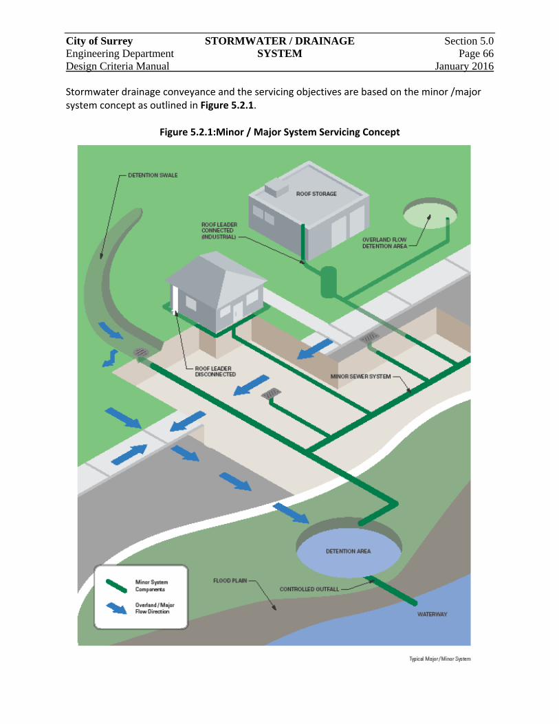
City of Surrey STORMWATER / DRAINAGE Section 5.0 Engineering Department SYSTEM Page 66 Design Criteria Manual January 2016
Stormwater drainage conveyance and the servicing objectives are based on the minor /major system concept as outlined in Figure 5.2.1.
Figure 5.2.1:Minor / Major System Servicing Concept

City of Surrey STORMWATER / DRAINAGE Section 5.0 Engineering Department SYSTEM Page 67 Design Criteria Manual January 2016
5.2.2 Submission Requirements
The Consultant shall conduct an analysis of the stormwater drainage system, from a development servicing perspective and capacity evaluation, at an early stage of the development and design process. All development proponents are required to submit the a Stormwater Control Plan (SWCP)that describes in detail how the proposed development will impact the existing drainage system and how the proposed major and minor drainage infrastructure meets the City’s drainage policies and design criteria. The SWCP should include:
a. Tributary areas in the catchment including existing and ultimate land‐use;
b. Impervious or Runoff coefficient values for each catchment area based on future OCP or actual ultimate land‐use;
c. The development area within the drainage catchment including all features such as roads, natural watercourses, watercourse crossing structures, and low or poorly drained areas;
d. Contour plan with 1.0m elevation interval (1:2500 scale);
e. Areas of major cut or fill (greater than 1.0m);
f. Plan view of existing and proposed drainage systems;
g. Hydrologic calculations summarized in table form and supporting parameters to a point 100m downstream of the discharge into an existing Trunk Storm Sewer or identified in the engineering comments. (Rational Method accepted for areas less than 20 hectares. The Hydrograph Method to be applied for areas exceeding 20 hectares);
h. Major and minor conveyance capacity;
i. Hydraulic considerations ‐ surcharged system impact, water flow on road surface. A profile of the 100‐year HGL against MBEs is required;
j. Major system (1:100‐year) flow routing internal and external to the development, including the direction of surface flows on roadways, other rights‐of‐way, and all surface flow routes; areas subject to ponding and depths of ponding; elevations of overflow points from local depressions; and details of channel cross sections. Where significant major system flows are expected to discharge or overflow to a watercourse, ravine, environmental reserve area, etc., the rate and projected frequency of such flows is to be noted;
k. Outfall capacity constraints including storm sewers and natural watercourses;
l. Control of discharges to meet downstream conditions such as prevention of erosion and flooding;
City of Surrey STORMWATER / DRAINAGE Section 5.0 Engineering Department SYSTEM Page 68 Design Criteria Manual January 2016
m. Recommendations for works required to address the above including any interim facility;
n. Location and sizes of detention facilities including summary of design flows, volumes, and control orifice sizing;
o. Show the HGL in the detention facility and account for potential backwater effects in the design of sewers draining into it;
p. Details of specialized drainage structures, if present;
q. Approach to groundwater management including groundwater emergence, for the protection of municipal and private infrastructure and property; and
r. Consideration of impact on the total watershed and recommendations in the ISMP, MDP and/or NCP (if applicable).
It is the Consultant’s responsibility to confirm the extent of the drainage catchments and obtain approval of the SWCP from the Engineer.
The Consultant may be required to prepare and submit an Erosion and Sediment Control Plan, in accordance with the City’s ESC By‐law. The Consultant will refer to this by‐law for requirements and submission details.
5.2.3 Methodology of Analysis
For analysis of stormwater drainage system, the extent and boundaries of the catchment area will be confirmed with the Engineer prior to analysis and design of further extensions to the City’s stormwater drainage system. Any and all sections of the stormwater drainage system which have calculated peak flows in excess of the Q pipe capacity, or channel, capacity will be deemed to be insufficient and out of capacity to allow additional flows to be discharged into the system. If required by the Engineer, the analysis of the stormwater drainage system will be determined from the most upstream point in the subject catchment area to the point downstream where the system discharges. Section 5.3 describes the rationale and parameters for determining hydrologic variables such as rate and amount of stormwater runoff in the design of stormwater drainage flow conveyance and storage facilities.
City of Surrey STORMWATER / DRAINAGE Section 5.0 Engineering Department SYSTEM Page 69 Design Criteria Manual January 2016
5.3 Stormwater Flow Generation
5.3.1 General
The Rational Method, due to its simplicity, is the preferred approach for the design of minor or major storm drainage system components which accommodate flows from catchments with an area of approximately 20 hectares (Ha) or smaller. The Hydrograph Method, using computer simulation programs, is required for catchments greater than 20 Ha. Computer simulation programs are also recommended for the design of erosion control and detention ponds because of their ability to run continuous simulations.
5.3.2 Rainfall Data
Data from the Surrey Kwantlen Park, Old Municipal Hall and White Rock STP AES rainfall gauges will be used in designing drainage infrastructure in the City. As shown in Figure 5.3.1, the three gauges are assigned to specific areas of the City from north to south to account for variation in rainfall distribution. Rainfall Intensity Duration Frequency (IDF) curves for 5 minutes to 24‐hour durations for each of the three stations are provided in Tables 5.3.1, 5.3.2, 5.3.3, as well as on Figures 5.3.2, 5.3.3, 5.3.4. Rainfall depths taken from these curves can be used with the Rational Method computations to calculate flows. Design storms that reflect historic conditions in Surrey can be used for Hydrograph Method computations. Tables 5.3.4, 5.3.5, 5.3.6 and 5.3.7 provide design storm hyetographs for areas covered by the Kwantlen Park rainfall gauge (as delineated in Figure 5.3.1) for durations of 1, 2, 6, 12 and 24 hours. For areas covered by the other two gauges, IDF curve values for the appropriate gauges, and return period and duration, will be used to pro‐rate the Kwantlen Park design hyetographs. Long duration rainstorms, which are typical for the Lower Mainland, last about three to five days. These events are critical for the effective functioning of stormwater detention facilities. The City has recorded two long duration, historical rainfall events in South Surrey. Rainfall data from these events, November 1996 and January 1997, presented in Table 5.3.8 and shown on Figure 5.3.5. As directed by the Engineer, these historical events must be used to assess the design performance of storage facilities. In addition, historical long duration wet weather periods, up to one month in duration, containing 5 to 100‐year events are to be used to confirm safe operation for these critical wet weather periods. Using the historical hourly rainfall data, appropriate critical periods have been selected and are tabulated in Table 5.3.10. The related hourly data for long duration performance analysis is available from the City in digital form.
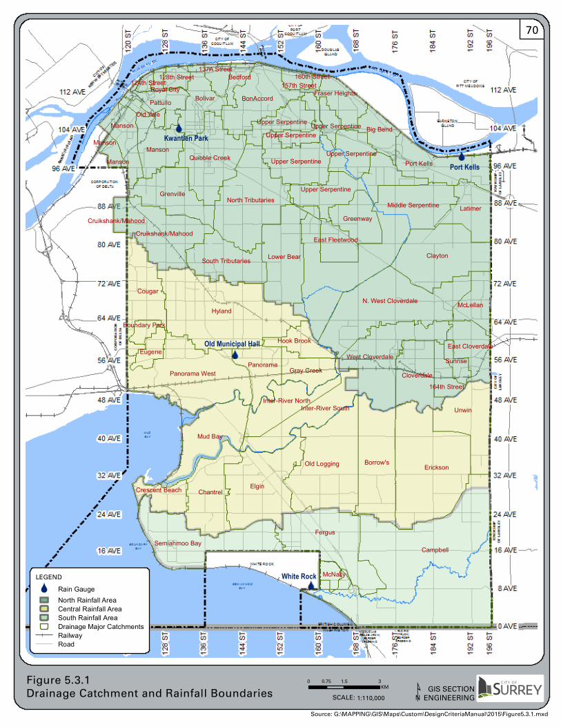
Kwantlen Park
Port Kells
Old Municipal Hall
White Rock
Elgin
Old Logging Borrow's
Fergus
McNally
Unwin
East Cloverdale
McLellan
Semiahmoo Bay
Crescent Beach
Manson
Lower Bear
Erickson
Campbell
South Tributaries
Cruikshank/Mahood
Middle Serpentine
Hook Brook
Gray Creek
Cougar
Eugene
Hyland
Panorama West Cloverdale
Bolivar
Upper Serpentine
Manson
GrenvilleNorth Tributaries
Panorama
Quibble Creek
Big Bend
West Cloverdale
N. West Cloverdale
Mud Bay
164th Street
Clayton
128th StreetRoyal City
124th Street
PattulloOld Yale
137A StreetBedford
Sunrise
Manson
160th Street
Boundary Park
Fraser Heights
Latimer
Port Kells
Inter-River South
Chantrel
Greenway
Upper Serpentine
Upper Serpentine
Upper Serpentine
Upper Serpentine
Upper Serpentine
Manson
Cruikshank/Mahood
East Fleetwood
Inter-River North
BonAccord157th Street
0 1.5 30.75KM
Figure 5.3.1Drainage Catchment and Rainfall Boundaries GIS SECTION
ENGINEERINGSCALE: 1:110,000 ¹
LEGEND
ÔÕ Rain GaugeNorth Rainfall AreaCentral Rainfall AreaSouth Rainfall AreaDrainage Major CatchmentsRailwayRoad
Source: G:\MAPPING\GIS\Maps\Custom\DesignCriteriaManual\2015\Figure5.3.1.mxd
70
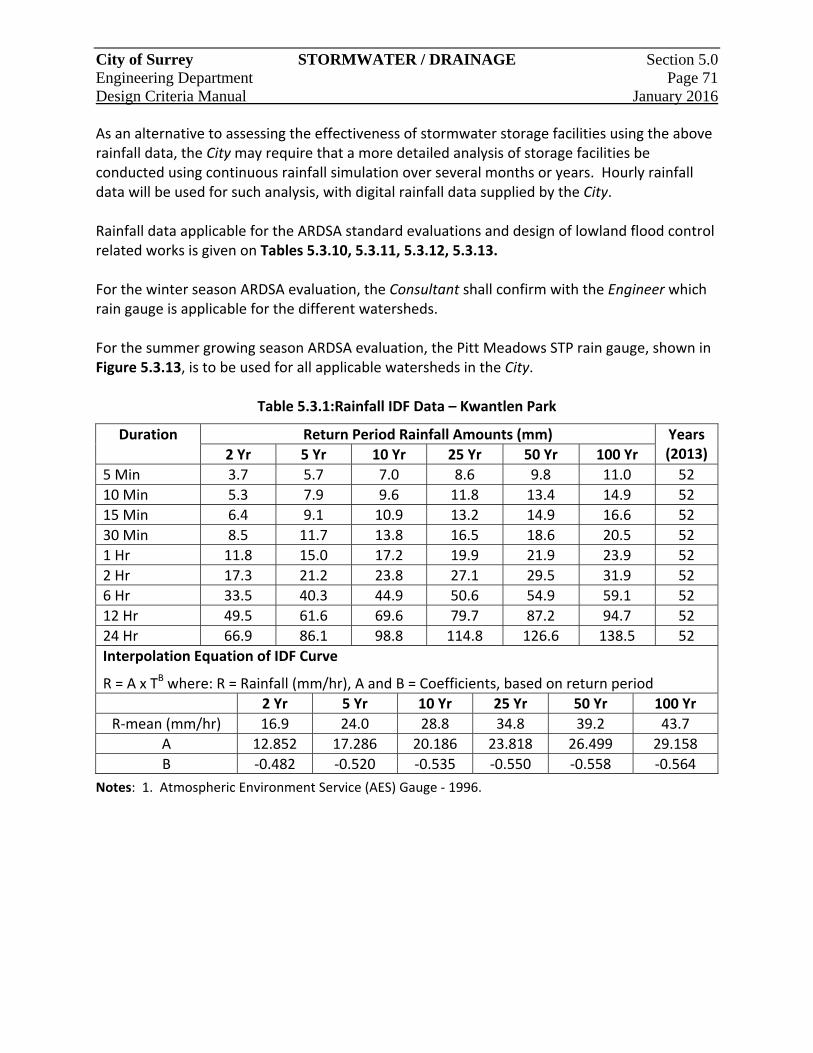
City of Surrey STORMWATER / DRAINAGE Section 5.0 Engineering Department Page 71 Design Criteria Manual January 2016
As an alternative to assessing the effectiveness of stormwater storage facilities using the above rainfall data, the City may require that a more detailed analysis of storage facilities be conducted using continuous rainfall simulation over several months or years. Hourly rainfall data will be used for such analysis, with digital rainfall data supplied by the City. Rainfall data applicable for the ARDSA standard evaluations and design of lowland flood control related works is given on Tables 5.3.10, 5.3.11, 5.3.12, 5.3.13. For the winter season ARDSA evaluation, the Consultant shall confirm with the Engineer which rain gauge is applicable for the different watersheds. For the summer growing season ARDSA evaluation, the Pitt Meadows STP rain gauge, shown in Figure 5.3.13, is to be used for all applicable watersheds in the City.
Table 5.3.1:Rainfall IDF Data – Kwantlen Park
Duration Return Period Rainfall Amounts (mm) Years (2013) 2 Yr 5 Yr 10 Yr 25 Yr 50 Yr 100 Yr
5 Min 3.7 5.7 7.0 8.6 9.8 11.0 52
10 Min 5.3 7.9 9.6 11.8 13.4 14.9 52
15 Min 6.4 9.1 10.9 13.2 14.9 16.6 52
30 Min 8.5 11.7 13.8 16.5 18.6 20.5 52
1 Hr 11.8 15.0 17.2 19.9 21.9 23.9 52
2 Hr 17.3 21.2 23.8 27.1 29.5 31.9 52
6 Hr 33.5 40.3 44.9 50.6 54.9 59.1 52
12 Hr 49.5 61.6 69.6 79.7 87.2 94.7 52
24 Hr 66.9 86.1 98.8 114.8 126.6 138.5 52
Interpolation Equation of IDF Curve
R = A x TB where: R = Rainfall (mm/hr), A and B = Coefficients, based on return period
2 Yr 5 Yr 10 Yr 25 Yr 50 Yr 100 Yr
R‐mean (mm/hr) 16.9 24.0 28.8 34.8 39.2 43.7
A 12.852 17.286 20.186 23.818 26.499 29.158
B ‐0.482 ‐0.520 ‐0.535 ‐0.550 ‐0.558 ‐0.564
Notes: 1. Atmospheric Environment Service (AES) Gauge ‐ 1996.
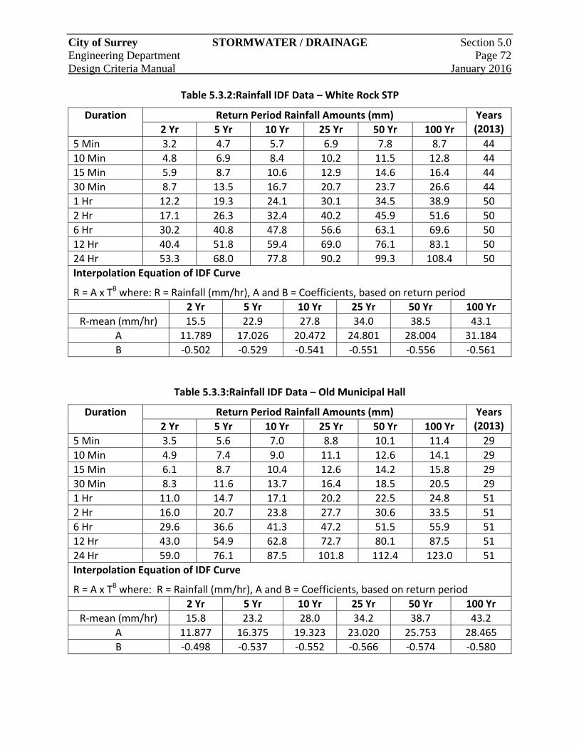
City of Surrey STORMWATER / DRAINAGE Section 5.0 Engineering Department Page 72 Design Criteria Manual January 2016
Table 5.3.2:Rainfall IDF Data – White Rock STP
Duration Return Period Rainfall Amounts (mm) Years (2013) 2 Yr 5 Yr 10 Yr 25 Yr 50 Yr 100 Yr
5 Min 3.2 4.7 5.7 6.9 7.8 8.7 44
10 Min 4.8 6.9 8.4 10.2 11.5 12.8 44
15 Min 5.9 8.7 10.6 12.9 14.6 16.4 44
30 Min 8.7 13.5 16.7 20.7 23.7 26.6 44
1 Hr 12.2 19.3 24.1 30.1 34.5 38.9 50
2 Hr 17.1 26.3 32.4 40.2 45.9 51.6 50
6 Hr 30.2 40.8 47.8 56.6 63.1 69.6 50
12 Hr 40.4 51.8 59.4 69.0 76.1 83.1 50
24 Hr 53.3 68.0 77.8 90.2 99.3 108.4 50
Interpolation Equation of IDF Curve
R = A x TB where: R = Rainfall (mm/hr), A and B = Coefficients, based on return period
2 Yr 5 Yr 10 Yr 25 Yr 50 Yr 100 Yr
R‐mean (mm/hr) 15.5 22.9 27.8 34.0 38.5 43.1
A 11.789 17.026 20.472 24.801 28.004 31.184
B ‐0.502 ‐0.529 ‐0.541 ‐0.551 ‐0.556 ‐0.561
Table 5.3.3:Rainfall IDF Data – Old Municipal Hall
Duration Return Period Rainfall Amounts (mm) Years (2013) 2 Yr 5 Yr 10 Yr 25 Yr 50 Yr 100 Yr
5 Min 3.5 5.6 7.0 8.8 10.1 11.4 29
10 Min 4.9 7.4 9.0 11.1 12.6 14.1 29
15 Min 6.1 8.7 10.4 12.6 14.2 15.8 29
30 Min 8.3 11.6 13.7 16.4 18.5 20.5 29
1 Hr 11.0 14.7 17.1 20.2 22.5 24.8 51
2 Hr 16.0 20.7 23.8 27.7 30.6 33.5 51
6 Hr 29.6 36.6 41.3 47.2 51.5 55.9 51
12 Hr 43.0 54.9 62.8 72.7 80.1 87.5 51
24 Hr 59.0 76.1 87.5 101.8 112.4 123.0 51
Interpolation Equation of IDF Curve
R = A x TB where: R = Rainfall (mm/hr), A and B = Coefficients, based on return period
2 Yr 5 Yr 10 Yr 25 Yr 50 Yr 100 Yr
R‐mean (mm/hr) 15.8 23.2 28.0 34.2 38.7 43.2
A 11.877 16.375 19.323 23.020 25.753 28.465
B ‐0.498 ‐0.537 ‐0.552 ‐0.566 ‐0.574 ‐0.580
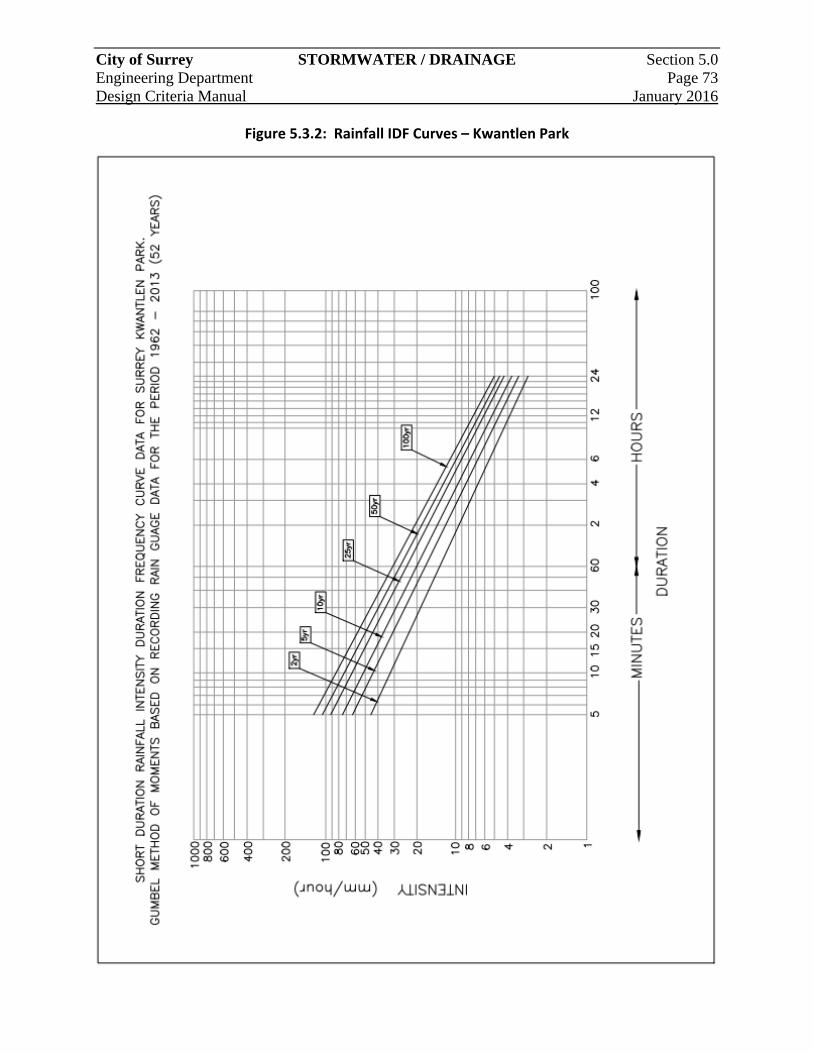
City of Surrey STORMWATER / DRAINAGE Section 5.0 Engineering Department Page 73 Design Criteria Manual January 2016
Figure 5.3.2: Rainfall IDF Curves – Kwantlen Park
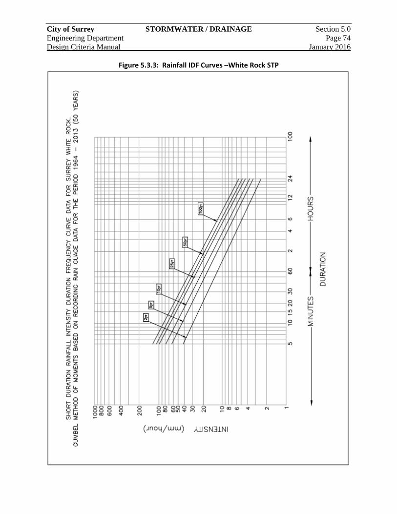
City of Surrey STORMWATER / DRAINAGE Section 5.0 Engineering Department Page 74 Design Criteria Manual January 2016
Figure 5.3.3: Rainfall IDF Curves –White Rock STP
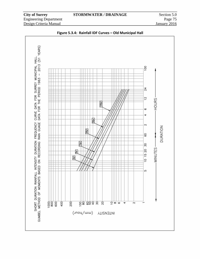
City of Surrey STORMWATER / DRAINAGE Section 5.0 Engineering Department Page 75 Design Criteria Manual January 2016
Figure 5.3.4: Rainfall IDF Curves – Old Municipal Hall
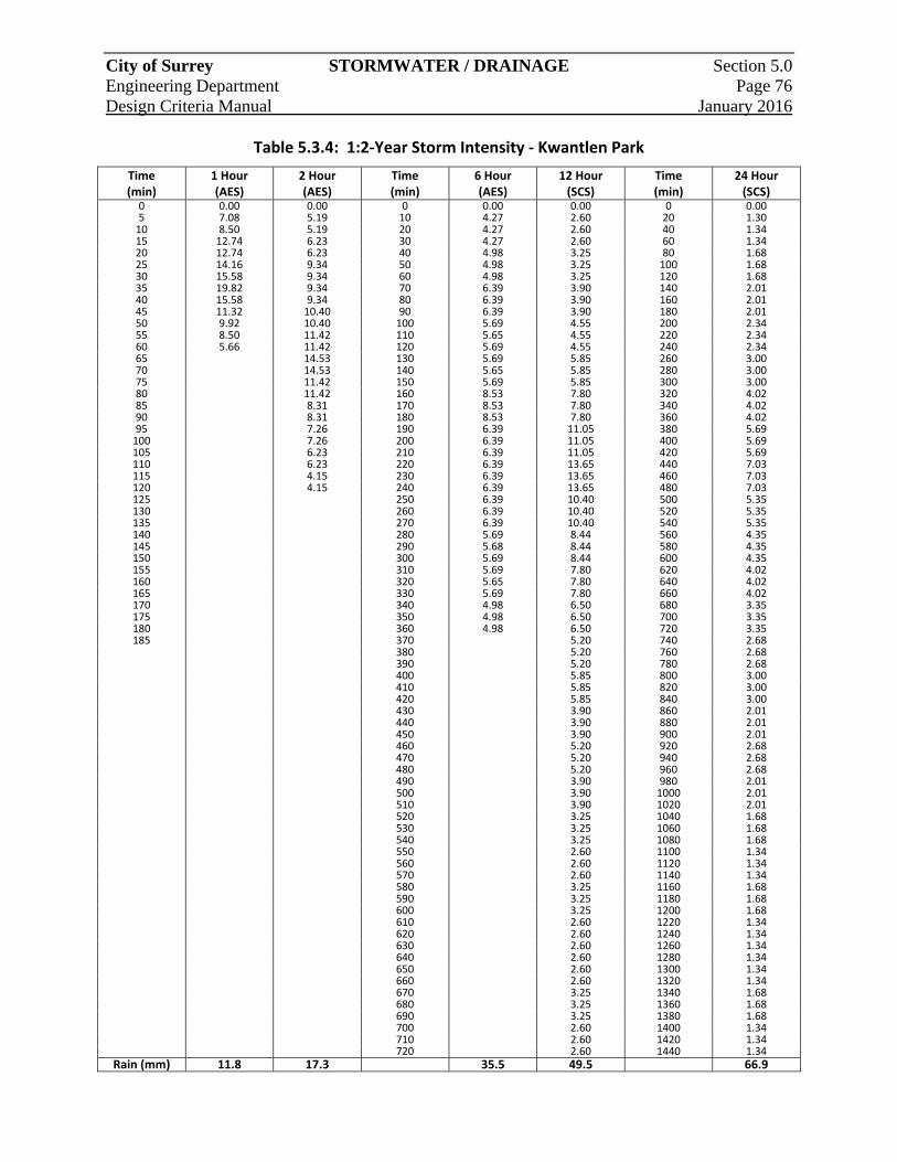
City of Surrey STORMWATER / DRAINAGE Section 5.0 Engineering Department Page 76 Design Criteria Manual January 2016
Table 5.3.4: 1:2‐Year Storm Intensity ‐ Kwantlen Park
Time (min)
1 Hour (AES)
2 Hour (AES)
Time (min)
6 Hour (AES)
12 Hour (SCS)
Time (min)
24 Hour (SCS)
0 0.00 0.00 0 0.00 0.00 0 0.005 7.08 5.19 10 4.27 2.60 20 1.3010 8.50 5.19 20 4.27 2.60 40 1.3415 12.74 6.23 30 4.27 2.60 60 1.3420 12.74 6.23 40 4.98 3.25 80 1.6825 14.16 9.34 50 4.98 3.25 100 1.6830 15.58 9.34 60 4.98 3.25 120 1.6835 19.82 9.34 70 6.39 3.90 140 2.0140 15.58 9.34 80 6.39 3.90 160 2.0145 11.32 10.40 90 6.39 3.90 180 2.0150 9.92 10.40 100 5.69 4.55 200 2.3455 8.50 11.42 110 5.65 4.55 220 2.3460 5.66 11.42 120 5.69 4.55 240 2.3465 14.53 130 5.69 5.85 260 3.0070 14.53 140 5.65 5.85 280 3.0075 11.42 150 5.69 5.85 300 3.0080 11.42 160 8.53 7.80 320 4.0285 8.31 170 8.53 7.80 340 4.0290 8.31 180 8.53 7.80 360 4.0295 7.26 190 6.39 11.05 380 5.69100 7.26 200 6.39 11.05 400 5.69105 6.23 210 6.39 11.05 420 5.69110 6.23 220 6.39 13.65 440 7.03115 4.15 230 6.39 13.65 460 7.03120 4.15 240 6.39 13.65 480 7.03125 250 6.39 10.40 500 5.35130 260 6.39 10.40 520 5.35135 270 6.39 10.40 540 5.35140 280 5.69 8.44 560 4.35145 290 5.68 8.44 580 4.35150 300 5.69 8.44 600 4.35155 310 5.69 7.80 620 4.02160 320 5.65 7.80 640 4.02165 330 5.69 7.80 660 4.02170 340 4.98 6.50 680 3.35175 350 4.98 6.50 700 3.35180 360 4.98 6.50 720 3.35185 370 5.20 740 2.68 380 5.20 760 2.68 390 5.20 780 2.68 400 5.85 800 3.00 410 5.85 820 3.00 420 5.85 840 3.00 430 3.90 860 2.01 440 3.90 880 2.01 450 3.90 900 2.01 460 5.20 920 2.68 470 5.20 940 2.68 480 5.20 960 2.68 490 3.90 980 2.01 500 3.90 1000 2.01 510 3.90 1020 2.01 520 3.25 1040 1.68 530 3.25 1060 1.68 540 3.25 1080 1.68 550 2.60 1100 1.34 560 2.60 1120 1.34 570 2.60 1140 1.34 580 3.25 1160 1.68 590 3.25 1180 1.68 600 3.25 1200 1.68 610 2.60 1220 1.34 620 2.60 1240 1.34 630 2.60 1260 1.34 640 2.60 1280 1.34 650 2.60 1300 1.34 660 2.60 1320 1.34 670 3.25 1340 1.68 680 3.25 1360 1.68 690 3.25 1380 1.68 700 2.60 1400 1.34 710 2.60 1420 1.34 720 2.60 1440 1.34
Rain (mm) 11.8 17.3 35.5 49.5 66.9
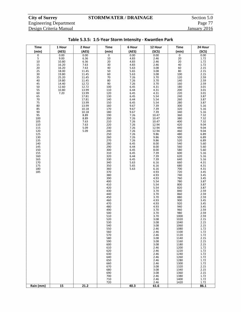
City of Surrey STORMWATER / DRAINAGE Section 5.0 Engineering Department Page 77 Design Criteria Manual January 2016
Table 5.3.5: 1:5‐Year Storm Intensity ‐ Kwantlen Park
Time (min)
1 Hour (AES)
2 Hour (AES)
Time (min)
6 Hour (AES)
12 Hour (SCS)
Time (min)
24 Hour (SCS)
0 0.00 0.00 0 0.00 0.00 0 0.005 9.00 6.36 10 4.83 2.46 20 1.7210 10.80 6.36 20 4.83 2.46 20 1.7215 16.20 7.63 30 4.83 2.46 40 1.7220 16.20 7.63 40 5.63 3.08 60 2.1525 18.00 11.45 50 5.65 3.08 80 2.1530 19.80 11.45 60 5.63 3.08 100 2.1535 25.20 11.45 70 7.26 3.70 120 2.5940 19.80 11.45 80 7.26 3.70 140 2.5945 14.40 12.72 90 7.26 3.70 160 2.5950 12.60 12.72 100 6.45 4.31 180 3.0155 10.80 13.99 110 6.44 4.31 200 3.0160 7.20 13.99 120 6.45 4.31 220 3.0165 17.81 130 6.45 5.54 240 3.8770 17.81 140 6.44 5.54 260 3.8775 13.99 150 6.45 5.54 280 3.8780 13.99 160 9.67 7.39 300 5.1685 10.18 170 9.67 7.39 320 5.1690 10.18 180 9.67 7.39 340 5.1695 8.89 190 7.26 10.47 360 7.32100 8.89 200 7.26 10.47 380 7.32105 7.63 210 7.26 10.47 400 7.32110 7.63 220 7.26 12.94 420 9.04115 5.09 230 7.26 12.94 440 9.04120 5.09 240 7.26 12.94 460 9.04125 250 7.26 9.86 480 6.89130 260 7.26 9.86 500 6.89135 270 7.26 9.86 520 6.89140 280 6.45 8.00 540 5.60145 290 6.44 8.00 560 5.60150 300 6.45 8.00 580 5.60155 310 6.45 7.39 600 5.16160 320 6.44 7.39 620 5.16165 330 6.45 7.39 640 5.16170 340 5.63 6.16 660 4.31175 350 5.65 6.16 680 4.31180 360 5.63 6.16 700 4.31185 370 4.93 720 3.45 380 4.93 740 3.45 390 4.93 760 3.45 400 5.54 780 3.87 410 5.54 800 3.87 420 5.54 820 3.87 430 3.70 840 2.59 440 3.70 860 2.59 450 3.70 880 2.59 460 4.93 900 3.45 470 4.93 920 3.45 480 4.93 940 3.45 490 3.70 960 2.59 500 3.70 980 2.59 510 3.70 1000 2.59 520 3.08 1020 2.15 530 3.08 1040 2.15 540 3.08 1060 2.15 550 2.46 1080 1.72 560 2.46 1100 1.72 570 2.46 1120 1.72 580 3.08 1140 2.15 590 3.08 1160 2.15 600 3.08 1180 2.15 610 2.46 1200 1.72 620 2.46 1220 1.72 630 2.46 1240 1.72 640 2.46 1260 1.72 650 2.46 1280 1.72 660 2.46 1300 1.72 670 3.08 1320 2.15 680 3.08 1340 2.15 690 3.08 1360 2.15 700 2.46 1380 1.72 710 2.46 1400 1.72 720 2.46 1420 1.72
Rain (mm) 15 21.2 40.3 61.6 86.1
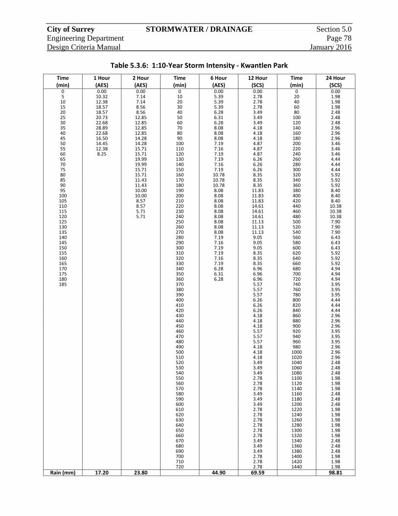
City of Surrey STORMWATER / DRAINAGE Section 5.0 Engineering Department Page 78 Design Criteria Manual January 2016
Table 5.3.6: 1:10‐Year Storm Intensity ‐ Kwantlen Park
Time (min)
1 Hour (AES)
2 Hour (AES)
Time (min)
6 Hour (AES)
12 Hour (SCS)
Time (min)
24 Hour (SCS)
0 0.00 0.00 0 0.00 0.00 0 0.005 10.32 7.14 10 5.39 2.78 20 1.9810 12.38 7.14 20 5.39 2.78 40 1.9815 18.57 8.56 30 5.39 2.78 60 1.9820 18.57 8.56 40 6.28 3.49 80 2.4825 20.73 12.85 50 6.31 3.49 100 2.4830 22.68 12.85 60 6.28 3.49 120 2.4835 28.89 12.85 70 8.08 4.18 140 2.9640 22.68 12.85 80 8.08 4.18 160 2.9645 16.50 14.28 90 8.08 4.18 180 2.9650 14.45 14.28 100 7.19 4.87 200 3.4655 12.38 15.71 110 7.16 4.87 220 3.4660 8.25 15.71 120 7.19 4.87 240 3.4665 19.99 130 7.19 6.26 260 4.4470 19.99 140 7.16 6.26 280 4.4475 15.71 150 7.19 6.26 300 4.4480 15.71 160 10.78 8.35 320 5.9285 11.43 170 10.78 8.35 340 5.9290 11.43 180 10.78 8.35 360 5.9295 10.00 190 8.08 11.83 380 8.40100 10.00 200 8.08 11.83 400 8.40105 8.57 210 8.08 11.83 420 8.40110 8.57 220 8.08 14.61 440 10.38115 5.71 230 8.08 14.61 460 10.38120 5.71 240 8.08 14.61 480 10.38125 250 8.08 11.13 500 7.90130 260 8.08 11.13 520 7.90135 270 8.08 11.13 540 7.90140 280 7.19 9.05 560 6.43145 290 7.16 9.05 580 6.43150 300 7.19 9.05 600 6.43155 310 7.19 8.35 620 5.92160 320 7.16 8.35 640 5.92165 330 7.19 8.35 660 5.92170 340 6.28 6.96 680 4.94175 350 6.31 6.96 700 4.94180 360 6.28 6.96 720 4.94185 370 5.57 740 3.95 380 5.57 760 3.95 390 5.57 780 3.95 400 6.26 800 4.44 410 6.26 820 4.44 420 6.26 840 4.44 430 4.18 860 2.96 440 4.18 880 2.96 450 4.18 900 2.96 460 5.57 920 3.95 470 5.57 940 3.95 480 5.57 960 3.95 490 4.18 980 2.96 500 4.18 1000 2.96 510 4.18 1020 2.96 520 3.49 1040 2.48 530 3.49 1060 2.48 540 3.49 1080 2.48 550 2.78 1100 1.98 560 2.78 1120 1.98 570 2.78 1140 1.98 580 3.49 1160 2.48 590 3.49 1180 2.48 600 3.49 1200 2.48 610 2.78 1220 1.98 620 2.78 1240 1.98 630 2.78 1260 1.98 640 2.78 1280 1.98 650 2.78 1300 1.98 660 2.78 1320 1.98 670 3.49 1340 2.48 680 3.49 1360 2.48 690 3.49 1380 2.48 700 2.78 1400 1.98 710 2.78 1420 1.98 720 2.78 1440 1.98
Rain (mm) 17.20 23.80 44.90 69.59 98.81
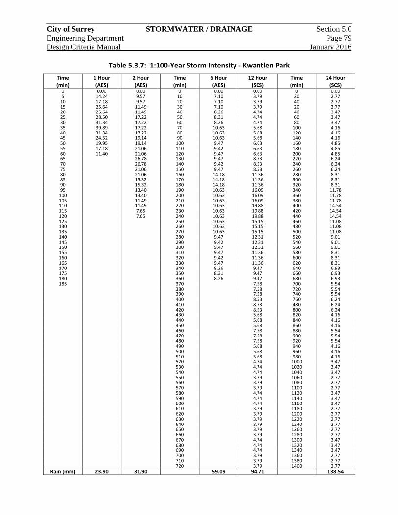
City of Surrey STORMWATER / DRAINAGE Section 5.0 Engineering Department Page 79 Design Criteria Manual January 2016
Table 5.3.7: 1:100‐Year Storm Intensity ‐ Kwantlen Park
Time (min)
1 Hour (AES)
2 Hour (AES)
Time (min)
6 Hour (AES)
12 Hour (SCS)
Time (min)
24 Hour (SCS)
0 0.00 0.00 0 0.00 0.00 0 0.005 14.24 9.57 10 7.10 3.79 20 2.7710 17.18 9.57 20 7.10 3.79 40 2.7715 25.64 11.49 30 7.10 3.79 20 2.7720 25.64 11.49 40 8.26 4.74 40 3.4725 28.50 17.22 50 8.31 4.74 60 3.4730 31.34 17.22 60 8.26 4.74 80 3.4735 39.89 17.22 70 10.63 5.68 100 4.1640 31.34 17.22 80 10.63 5.68 120 4.1645 24.52 19.14 90 10.63 5.68 140 4.1650 19.95 19.14 100 9.47 6.63 160 4.8555 17.18 21.06 110 9.42 6.63 180 4.8560 11.40 21.06 120 9.47 6.63 200 4.8565 26.78 130 9.47 8.53 220 6.2470 26.78 140 9.42 8.53 240 6.2475 21.06 150 9.47 8.53 260 6.2480 21.06 160 14.18 11.36 280 8.3185 15.32 170 14.18 11.36 300 8.3190 15.32 180 14.18 11.36 320 8.3195 13.40 190 10.63 16.09 340 11.78100 13.40 200 10.63 16.09 360 11.78105 11.49 210 10.63 16.09 380 11.78110 11.49 220 10.63 19.88 400 14.54115 7.65 230 10.63 19.88 420 14.54120 7.65 240 10.63 19.88 440 14.54125 250 10.63 15.15 460 11.08130 260 10.63 15.15 480 11.08135 270 10.63 15.15 500 11.08140 280 9.47 12.31 520 9.01145 290 9.42 12.31 540 9.01150 300 9.47 12.31 560 9.01155 310 9.47 11.36 580 8.31160 320 9.42 11.36 600 8.31165 330 9.47 11.36 620 8.31170 340 8.26 9.47 640 6.93175 350 8.31 9.47 660 6.93180 360 8.26 9.47 680 6.93185 370 7.58 700 5.54 380 7.58 720 5.54 390 7.58 740 5.54 400 8.53 760 6.24 410 8.53 480 6.24 420 8.53 800 6.24 430 5.68 820 4.16 440 5.68 840 4.16 450 5.68 860 4.16 460 7.58 880 5.54 470 7.58 900 5.54 480 7.58 920 5.54 490 5.68 940 4.16 500 5.68 960 4.16 510 5.68 980 4.16 520 4.74 1000 3.47 530 4.74 1020 3.47 540 4.74 1040 3.47 550 3.79 1060 2.77 560 3.79 1080 2.77 570 3.79 1100 2.77 580 4.74 1120 3.47 590 4.74 1140 3.47 600 4.74 1160 3.47 610 3.79 1180 2.77 620 3.79 1200 2.77 630 3.79 1220 2.77 640 3.79 1240 2.77 650 3.79 1260 2.77 660 3.79 1280 2.77 670 4.74 1300 3.47 680 4.74 1320 3.47 690 4.74 1340 3.47 700 3.79 1360 2.77 710 3.79 1380 2.77 720 3.79 1400 2.77
Rain (mm) 23.90 31.90 59.09 94.71 138.54
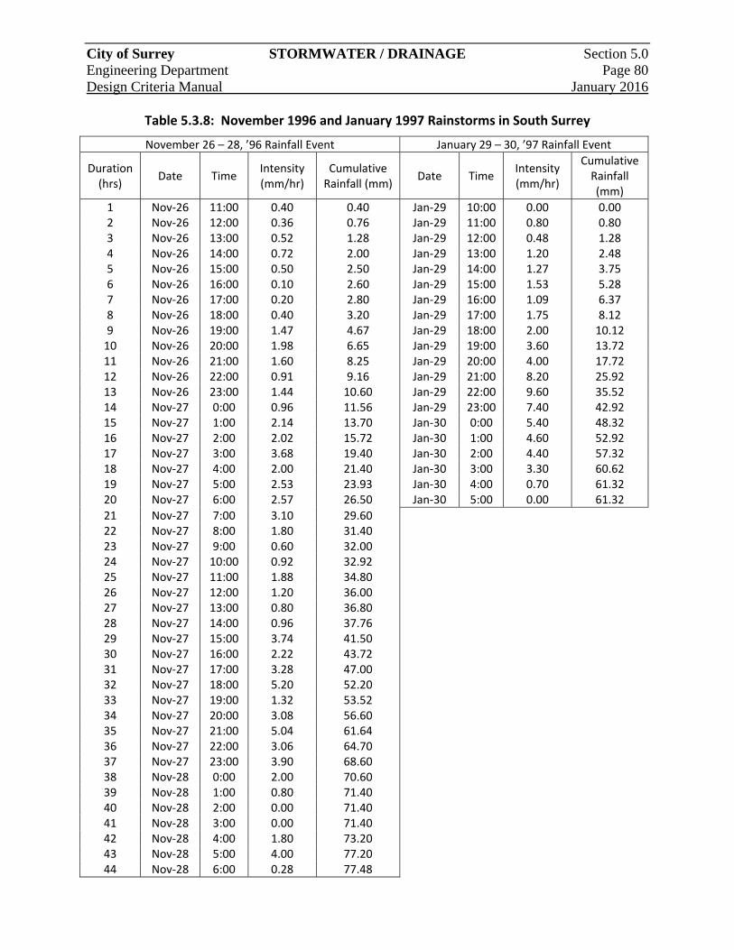
City of Surrey STORMWATER / DRAINAGE Section 5.0 Engineering Department Page 80 Design Criteria Manual January 2016
Table 5.3.8: November 1996 and January 1997 Rainstorms in South Surrey
November 26 – 28, ’96 Rainfall Event January 29 – 30, ’97 Rainfall Event
Duration (hrs)
Date Time Intensity (mm/hr)
Cumulative Rainfall (mm)
Date Time Intensity (mm/hr)
Cumulative Rainfall (mm)
1 Nov‐26 11:00 0.40 0.40 Jan‐29 10:00 0.00 0.002 Nov‐26 12:00 0.36 0.76 Jan‐29 11:00 0.80 0.803 Nov‐26 13:00 0.52 1.28 Jan‐29 12:00 0.48 1.284 Nov‐26 14:00 0.72 2.00 Jan‐29 13:00 1.20 2.485 Nov‐26 15:00 0.50 2.50 Jan‐29 14:00 1.27 3.756 Nov‐26 16:00 0.10 2.60 Jan‐29 15:00 1.53 5.287 Nov‐26 17:00 0.20 2.80 Jan‐29 16:00 1.09 6.378 Nov‐26 18:00 0.40 3.20 Jan‐29 17:00 1.75 8.129 Nov‐26 19:00 1.47 4.67 Jan‐29 18:00 2.00 10.1210 Nov‐26 20:00 1.98 6.65 Jan‐29 19:00 3.60 13.7211 Nov‐26 21:00 1.60 8.25 Jan‐29 20:00 4.00 17.7212 Nov‐26 22:00 0.91 9.16 Jan‐29 21:00 8.20 25.9213 Nov‐26 23:00 1.44 10.60 Jan‐29 22:00 9.60 35.5214 Nov‐27 0:00 0.96 11.56 Jan‐29 23:00 7.40 42.9215 Nov‐27 1:00 2.14 13.70 Jan‐30 0:00 5.40 48.3216 Nov‐27 2:00 2.02 15.72 Jan‐30 1:00 4.60 52.9217 Nov‐27 3:00 3.68 19.40 Jan‐30 2:00 4.40 57.3218 Nov‐27 4:00 2.00 21.40 Jan‐30 3:00 3.30 60.6219 Nov‐27 5:00 2.53 23.93 Jan‐30 4:00 0.70 61.3220 Nov‐27 6:00 2.57 26.50 Jan‐30 5:00 0.00 61.32
21 Nov‐27 7:00 3.10 29.60 22 Nov‐27 8:00 1.80 31.40 23 Nov‐27 9:00 0.60 32.00 24 Nov‐27 10:00 0.92 32.92 25 Nov‐27 11:00 1.88 34.80 26 Nov‐27 12:00 1.20 36.00 27 Nov‐27 13:00 0.80 36.80 28 Nov‐27 14:00 0.96 37.76 29 Nov‐27 15:00 3.74 41.50 30 Nov‐27 16:00 2.22 43.72 31 Nov‐27 17:00 3.28 47.00 32 Nov‐27 18:00 5.20 52.20 33 Nov‐27 19:00 1.32 53.52 34 Nov‐27 20:00 3.08 56.60 35 Nov‐27 21:00 5.04 61.64 36 Nov‐27 22:00 3.06 64.70 37 Nov‐27 23:00 3.90 68.60 38 Nov‐28 0:00 2.00 70.60 39 Nov‐28 1:00 0.80 71.40 40 Nov‐28 2:00 0.00 71.40 41 Nov‐28 3:00 0.00 71.40 42 Nov‐28 4:00 1.80 73.20 43 Nov‐28 5:00 4.00 77.20 44 Nov‐28 6:00 0.28 77.48
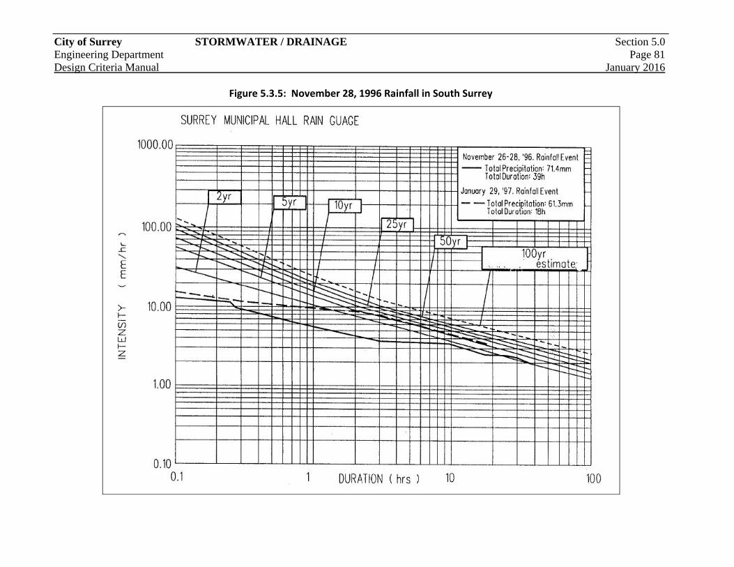
City of Surrey STORMWATER / DRAINAGE Section 5.0 Engineering Department Page 81 Design Criteria Manual January 2016
Figure 5.3.5: November 28, 1996 Rainfall in South Surrey
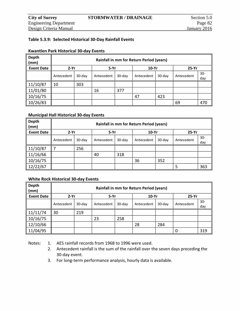
City of Surrey STORMWATER / DRAINAGE Section 5.0 Engineering Department Page 82 Design Criteria Manual January 2016
Table 5.3.9: Selected Historical 30‐Day Rainfall Events
Kwantlen Park Historical 30‐day Events
Depth (mm)
Rainfall in mm for Return Period (years)
Event Date 2‐Yr 5‐Yr 10‐Yr 25‐Yr
Antecedent 30‐day Antecedent 30‐day Antecedent 30‐day Antecedent 30‐day
11/10/87 10 303
11/01/80 16 377
10/16/75 47 423
10/26/83 69 470
Municipal Hall Historical 30‐day Events
Depth (mm)
Rainfall in mm for Return Period (years)
Event Date 2‐Yr 5‐Yr 10‐Yr 25‐Yr
Antecedent 30‐day Antecedent 30‐day Antecedent 30‐day Antecedent 30‐day
11/10/87 7 256
11/16/66 40 318
10/16/75 36 352
12/22/67 5 363
White Rock Historical 30‐day Events
Depth (mm)
Rainfall in mm for Return Period (years)
Event Date 2‐Yr 5‐Yr 10‐Yr 25‐Yr
Antecedent 30‐day Antecedent 30‐day Antecedent 30‐day Antecedent 30‐day
11/11/74 30 219
10/16/75 23 258
12/10/66 28 284
11/04/95 0 319
Notes: 1. AES rainfall records from 1968 to 1996 were used. 2. Antecedent rainfall is the sum of the rainfall over the seven days preceding the
30‐day event. 3. For long‐term performance analysis, hourly data is available.

City of Surrey STORMWATER / DRAINAGE Section 5.0 Engineering Department Page 83 Design Criteria Manual January 2016
Table 5.3.10:ARDSA Storm Distribution – Kwantlen Park Winter Season
Time (hour)
10‐Year Winter Season (5 day)Hourly Rainfall (mm)
Time(hour)
10‐Year Winter Season (5 day) Hourly Rainfall (mm)
1 0.90 61 0.002 2.20 62 0.003 0.40 63 0.004 0.90 64 2.085 0.70 65 1.506 0.20 66 0.007 1.70 67 0.238 2.80 68 0.009 1.50 69 0.0010 1.50 70 0.0011 2.80 71 0.0012 2.60 72 0.4613 2.08 73 0.6914 2.58 74 0.0015 5.20 75 0.0016 8.68 76 0.0017 8.48 77 2.3118 9.38 78 11.31 19 4.97 79 5.6520 5.17 80 1.0421 3.15 81 0.4622 3.82 82 0.2323 5.53 83 0.0024 5.42 84 0.0025 2.23 85 0.0026 2.03 86 0.0027 0.80 87 0.2328 2.90 88 0.0029 3.70 89 0.0030 3.00 90 0.0031 1.81 91 0.0032 3.38 92 0.0033 2.39 93 0.0034 1.68 94 0.0035 3.12 95 0.0036 1.62 96 0.2337 1.62 97 0.8138 0.00 98 1.2739 0.00 99 0.0040 0.00 100 0.5841 0.00 101 0.0042 1.87 102 0.2343 2.79 103 0.8144 2.44 104 0.0045 0.00 105 0.0046 0.00 106 0.5847 0.00 107 1.2748 2.11 108 1.6249 1.04 109 0.0050 0.46 110 0.0051 0.00 111 0.0052 0.81 112 0.0053 0.81 113 0.0054 2.65 114 0.0055 0.81 115 0.0056 0.00 116 1.6257 0.46 117 2.1958 0.46 118 2.5459 0.00 119 1.6260 0.00 120 1.15 Total 172.33
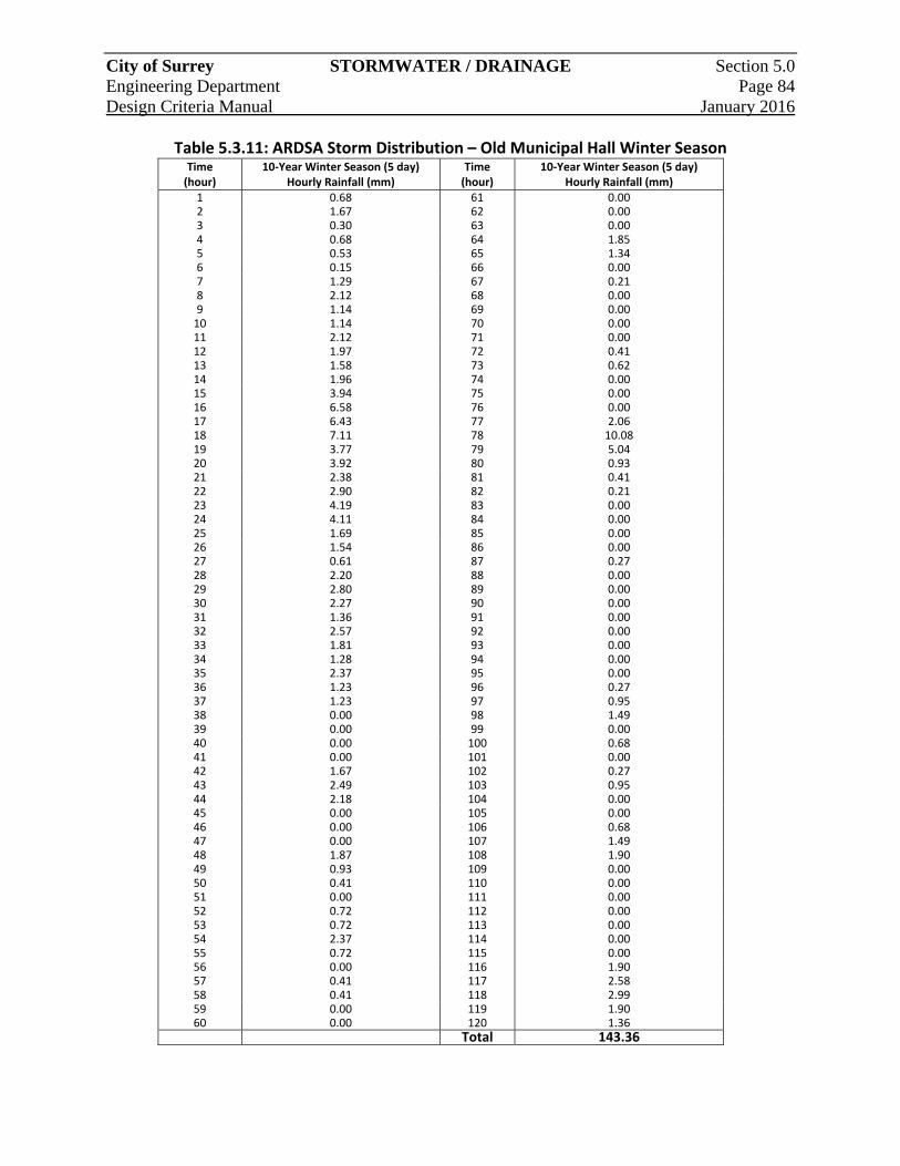
City of Surrey STORMWATER / DRAINAGE Section 5.0 Engineering Department Page 84 Design Criteria Manual January 2016
Table 5.3.11: ARDSA Storm Distribution – Old Municipal Hall Winter Season Time (hour)
10‐Year Winter Season (5 day)Hourly Rainfall (mm)
Time(hour)
10‐Year Winter Season (5 day) Hourly Rainfall (mm)
1 0.68 61 0.002 1.67 62 0.003 0.30 63 0.004 0.68 64 1.855 0.53 65 1.346 0.15 66 0.007 1.29 67 0.218 2.12 68 0.009 1.14 69 0.0010 1.14 70 0.0011 2.12 71 0.0012 1.97 72 0.4113 1.58 73 0.6214 1.96 74 0.0015 3.94 75 0.0016 6.58 76 0.0017 6.43 77 2.0618 7.11 78 10.08 19 3.77 79 5.0420 3.92 80 0.9321 2.38 81 0.4122 2.90 82 0.2123 4.19 83 0.0024 4.11 84 0.0025 1.69 85 0.0026 1.54 86 0.0027 0.61 87 0.2728 2.20 88 0.0029 2.80 89 0.0030 2.27 90 0.0031 1.36 91 0.0032 2.57 92 0.0033 1.81 93 0.0034 1.28 94 0.0035 2.37 95 0.0036 1.23 96 0.2737 1.23 97 0.9538 0.00 98 1.4939 0.00 99 0.0040 0.00 100 0.6841 0.00 101 0.0042 1.67 102 0.2743 2.49 103 0.9544 2.18 104 0.0045 0.00 105 0.0046 0.00 106 0.6847 0.00 107 1.4948 1.87 108 1.9049 0.93 109 0.0050 0.41 110 0.0051 0.00 111 0.0052 0.72 112 0.0053 0.72 113 0.0054 2.37 114 0.0055 0.72 115 0.0056 0.00 116 1.9057 0.41 117 2.5858 0.41 118 2.9959 0.00 119 1.9060 0.00 120 1.36 Total 143.36
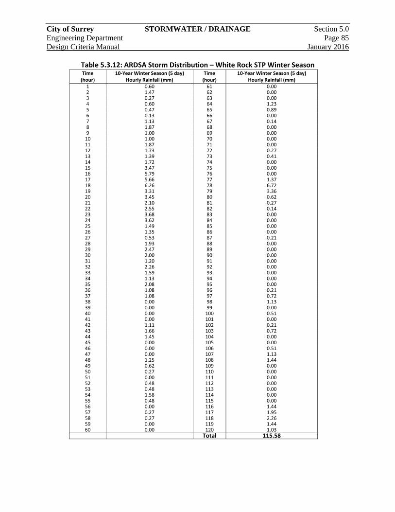
City of Surrey STORMWATER / DRAINAGE Section 5.0 Engineering Department Page 85 Design Criteria Manual January 2016
Table 5.3.12: ARDSA Storm Distribution – White Rock STP Winter Season Time (hour)
10‐Year Winter Season (5 day)Hourly Rainfall (mm)
Time(hour)
10‐Year Winter Season (5 day) Hourly Rainfall (mm)
1 0.60 61 0.002 1.47 62 0.003 0.27 63 0.004 0.60 64 1.235 0.47 65 0.896 0.13 66 0.007 1.13 67 0.148 1.87 68 0.009 1.00 69 0.0010 1.00 70 0.0011 1.87 71 0.0012 1.73 72 0.2713 1.39 73 0.4114 1.72 74 0.0015 3.47 75 0.0016 5.79 76 0.0017 5.66 77 1.3718 6.26 78 6.7219 3.31 79 3.3620 3.45 80 0.6221 2.10 81 0.2722 2.55 82 0.1423 3.68 83 0.0024 3.62 84 0.0025 1.49 85 0.0026 1.35 86 0.0027 0.53 87 0.2128 1.93 88 0.0029 2.47 89 0.0030 2.00 90 0.0031 1.20 91 0.0032 2.26 92 0.0033 1.59 93 0.0034 1.13 94 0.0035 2.08 95 0.0036 1.08 96 0.2137 1.08 97 0.7238 0.00 98 1.1339 0.00 99 0.0040 0.00 100 0.5141 0.00 101 0.0042 1.11 102 0.2143 1.66 103 0.7244 1.45 104 0.0045 0.00 105 0.0046 0.00 106 0.5147 0.00 107 1.1348 1.25 108 1.4449 0.62 109 0.0050 0.27 110 0.0051 0.00 111 0.0052 0.48 112 0.0053 0.48 113 0.0054 1.58 114 0.0055 0.48 115 0.0056 0.00 116 1.4457 0.27 117 1.9558 0.27 118 2.2659 0.00 119 1.4460 0.00 120 1.03 Total 115.58
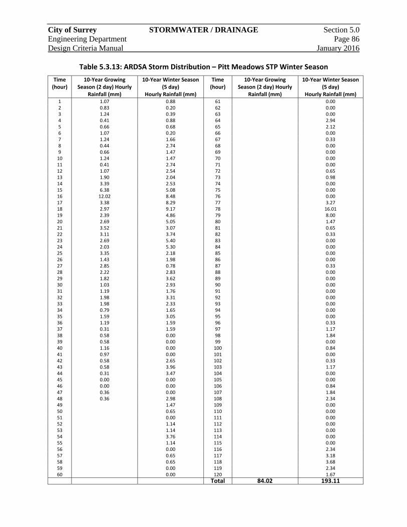
City of Surrey STORMWATER / DRAINAGE Section 5.0 Engineering Department Page 86 Design Criteria Manual January 2016
Table 5.3.13: ARDSA Storm Distribution – Pitt Meadows STP Winter Season
Time (hour)
10‐Year Growing Season (2 day) Hourly
Rainfall (mm)
10‐Year Winter Season (5 day)
Hourly Rainfall (mm)
Time (hour)
10‐Year Growing Season (2 day) Hourly
Rainfall (mm)
10‐Year Winter Season (5 day)
Hourly Rainfall (mm) 1 1.07 0.88 61 0.002 0.83 0.20 62 0.003 1.24 0.39 63 0.004 0.41 0.88 64 2.945 0.66 0.68 65 2.126 1.07 0.20 66 0.007 1.24 1.66 67 0.338 0.44 2.74 68 0.009 0.66 1.47 69 0.0010 1.24 1.47 70 0.0011 0.41 2.74 71 0.0012 1.07 2.54 72 0.6513 1.90 2.04 73 0.9814 3.39 2.53 74 0.0015 6.38 5.08 75 0.0016 12.02 8.48 76 0.0017 3.38 8.29 77 3.2718 2.97 9.17 78 16.0119 2.39 4.86 79 8.0020 2.69 5.05 80 1.4721 3.52 3.07 81 0.6522 3.11 3.74 82 0.3323 2.69 5.40 83 0.0024 2.03 5.30 84 0.0025 3.35 2.18 85 0.0026 1.43 1.98 86 0.0027 2.85 0.78 87 0.3328 2.22 2.83 88 0.0029 1.82 3.62 89 0.0030 1.03 2.93 90 0.0031 1.19 1.76 91 0.0032 1.98 3.31 92 0.0033 1.98 2.33 93 0.0034 0.79 1.65 94 0.0035 1.59 3.05 95 0.0036 1.19 1.59 96 0.3337 0.31 1.59 97 1.1738 0.58 0.00 98 1.8439 0.58 0.00 99 0.0040 1.16 0.00 100 0.8441 0.97 0.00 101 0.0042 0.58 2.65 102 0.3343 0.58 3.96 103 1.1744 0.31 3.47 104 0.0045 0.00 0.00 105 0.0046 0.00 0.00 106 0.8447 0.36 0.00 107 1.8448 0.36 2.98 108 2.3449 1.47 109 0.0050 0.65 110 0.0051 0.00 111 0.0052 1.14 112 0.0053 1.14 113 0.0054 3.76 114 0.0055 1.14 115 0.0056 0.00 116 2.3457 0.65 117 3.1858 0.65 118 3.6859 0.00 119 2.3460 0.00 120 1.67
Total 84.02 193.11

City of Surrey STORMWATER / DRAINAGE Section 5.0 Engineering Department Page 87 Design Criteria Manual January 2016
5.3.3 Rational Method
The Rational Method is the preferred approach for the design of minor or major storm drainage with an area of approximately 20 hectares (Ha) or smaller, and the design calculations should be presented in a format similar to Table 5.3.14. 5.3.3.1 Formula
The Rational Method shall follow the following formula: Q = RAIN Where: Q = Flow in cubic metres per second (m3/s) R = Runoff coefficient A = Drainage area in hectares (Ha) I = Rainfall intensity in mm/hr N = Conversion factor 0.00278
5.3.3.2 Drainage Area
The extent of the tributary drainage areas for the storm drainage system being designed will be determined using the natural and/or the proposed contours of the land, and it is the Consultant’s responsibility to confirm the extent of the drainage areas with the Engineer.
5.3.3.3 Runoff Coefficients
Runoff coefficients used shall be determined from the effective impervious ratio, and cross referenced with Table 5.3.15. These coefficients are the minimum values to be used.
Table 5.3.15: Runoff Coefficients
Description of Area %
Imperviousness Runoff Coefficient
(5 yr Event) Runoff Coefficient (100 yr Event)
Commercial 90 0.80 0.95 Industrial 90 0.80 0.95 Residential RA, RA‐G 50 0.45 0.54 RH, RH‐G 55 0.50 0.60 RF, RF‐SS, RM‐D 65 0.60 0.72 RF‐G, RM‐M, RM‐10, RM‐15, RM‐19, RM‐30, RM‐45, RM‐70 65 0.60 0.72
RMC‐150, RF‐9, RF‐12, RF‐SD, RM‐135, RMC‐135 80 0.70 0.84
Parks, Playgrounds, Cemeteries; Agricultural Land 20 0.25** 0.30
Institution; School; Church 80 0.75 0.90
**Passive use parks may reduce coefficient to 0.13.
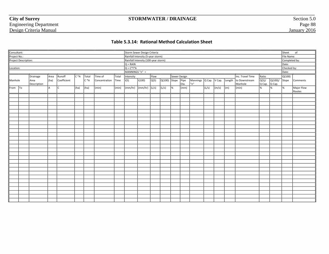
City of Surrey STORMWATER / DRAINAGE Section 5.0 Engineering Department Page 88 Design Criteria Manual January 2016
Table 5.3.14: Rational Method Calculation Sheet Consultant: Storm Sewer Design Criteria Sheet of
Project No.: Rainfall Intensity (5‐year storm) File Name:
Project Description: Rainfall Intensity (100‐year storm) Completed by:
Q = RAIN Date:
Location: Q = C*I*A Checked by:
MANNINGS "n" = Date:
Drainage Area Runoff C *A Total Time of Total Intensity Flow Sewer Design Inc. Travel Time Ratio Q(100)
Manhole Area (ha) Coefficient C *A Concentration Time I(5) I(100) Q(5) Q(100) Slope Pipe Mannings Q Cap. V Cap. Length to Downstream Q(5)/ Q(100)/ Slope Comments Description Dia. "n" Manhole Q Cap. Q Cap.
From To A C (ha) (ha) (min) (min) (mm/hr) (mm/hr) (L/s) (L/s) % (mm) (L/s) (m/s) (m) (min) % % % Major Flow Routes
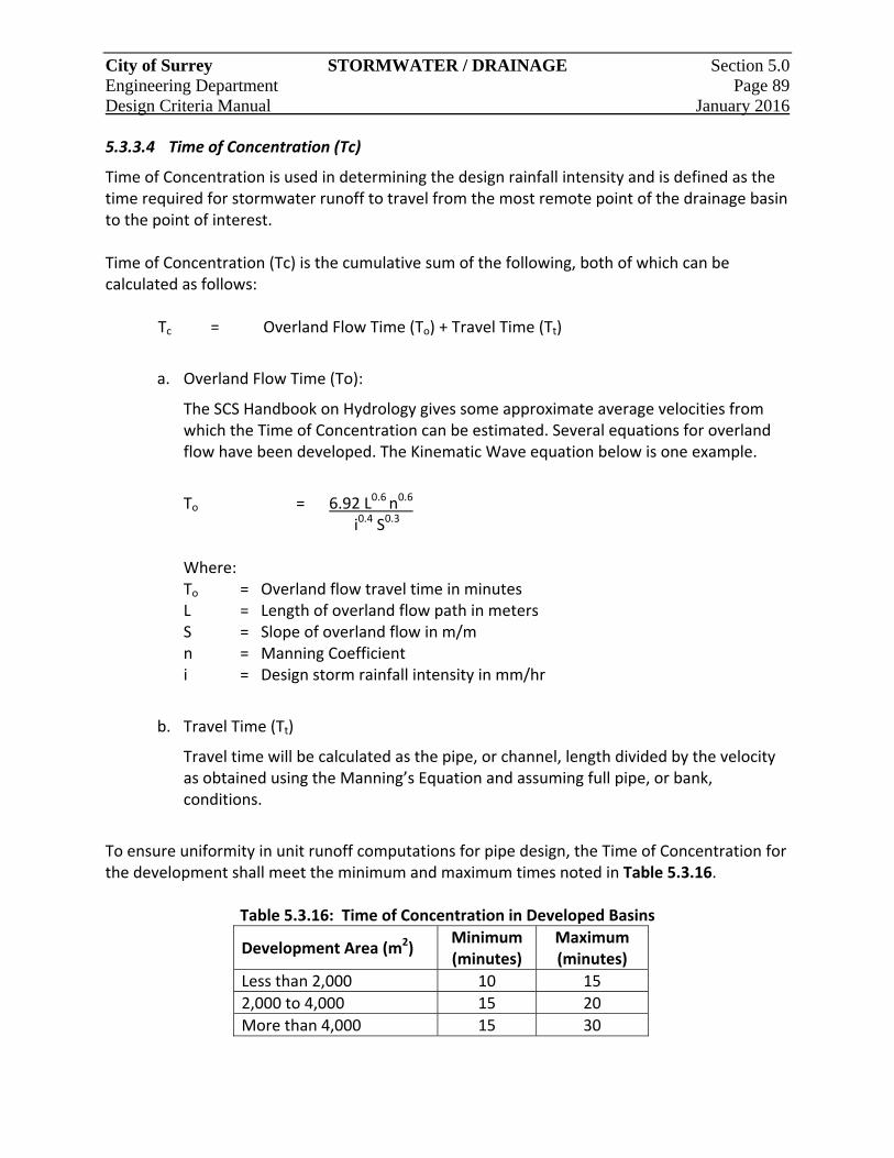
City of Surrey STORMWATER / DRAINAGE Section 5.0 Engineering Department Page 89 Design Criteria Manual January 2016
5.3.3.4 Time of Concentration (Tc)
Time of Concentration is used in determining the design rainfall intensity and is defined as the time required for stormwater runoff to travel from the most remote point of the drainage basin to the point of interest.
Time of Concentration (Tc) is the cumulative sum of the following, both of which can be calculated as follows:
Tc = Overland Flow Time (To) + Travel Time (Tt)
a. Overland Flow Time (To):
The SCS Handbook on Hydrology gives some approximate average velocities from which the Time of Concentration can be estimated. Several equations for overland flow have been developed. The Kinematic Wave equation below is one example.
To = 6.92 L0.6 n0.6
i0.4 S0.3
Where: To = Overland flow travel time in minutes L = Length of overland flow path in meters S = Slope of overland flow in m/m n = Manning Coefficient i = Design storm rainfall intensity in mm/hr
b. Travel Time (Tt)
Travel time will be calculated as the pipe, or channel, length divided by the velocity as obtained using the Manning’s Equation and assuming full pipe, or bank, conditions.
To ensure uniformity in unit runoff computations for pipe design, the Time of Concentration for the development shall meet the minimum and maximum times noted in Table 5.3.16.
Table 5.3.16: Time of Concentration in Developed Basins
Development Area (m2) Minimum (minutes)
Maximum (minutes)
Less than 2,000 10 15
2,000 to 4,000 15 20
More than 4,000 15 30
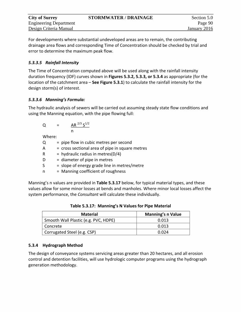
City of Surrey STORMWATER / DRAINAGE Section 5.0 Engineering Department Page 90 Design Criteria Manual January 2016
For developments where substantial undeveloped areas are to remain, the contributing drainage area flows and corresponding Time of Concentration should be checked by trial and error to determine the maximum peak flow. 5.3.3.5 Rainfall Intensity
The Time of Concentration computed above will be used along with the rainfall intensity duration frequency (IDF) curves shown in Figures 5.3.2, 5.3.3, or 5.3.4 as appropriate (for the location of the catchment area – See Figure 5.3.1) to calculate the rainfall intensity for the design storm(s) of interest. 5.3.3.6 Manning’s Formula:
The hydraulic analysis of sewers will be carried out assuming steady state flow conditions and using the Manning equation, with the pipe flowing full:
Q = AR 2/3 S1/2 n Where: Q = pipe flow in cubic metres per second A = cross sectional area of pipe in square metres R = hydraulic radius in metres(D/4) D = diameter of pipe in metres S = slope of energy grade line in metres/metre n = Manning coefficient of roughness
Manning’s n values are provided in Table 5.3.17 below, for typical material types, and these values allow for some minor losses at bends and manholes. Where minor local losses affect the system performance, the Consultant will calculate these individually.
Table 5.3.17: Manning’s N Values for Pipe Material
Material Manning’s n Value
Smooth Wall Plastic (e.g. PVC, HDPE) 0.013
Concrete 0.013
Corrugated Steel (e.g. CSP) 0.024
5.3.4 Hydrograph Method
The design of conveyance systems servicing areas greater than 20 hectares, and all erosion control and detention facilities, will use hydrologic computer programs using the hydrograph generation methodology.
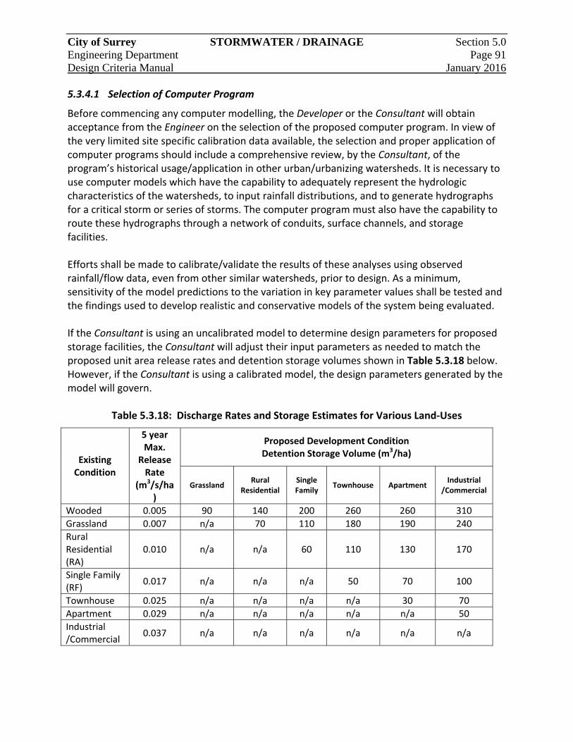
City of Surrey STORMWATER / DRAINAGE Section 5.0 Engineering Department Page 91 Design Criteria Manual January 2016
5.3.4.1 Selection of Computer Program
Before commencing any computer modelling, the Developer or the Consultant will obtain acceptance from the Engineer on the selection of the proposed computer program. In view of the very limited site specific calibration data available, the selection and proper application of computer programs should include a comprehensive review, by the Consultant, of the program’s historical usage/application in other urban/urbanizing watersheds. It is necessary to use computer models which have the capability to adequately represent the hydrologic characteristics of the watersheds, to input rainfall distributions, and to generate hydrographs for a critical storm or series of storms. The computer program must also have the capability to route these hydrographs through a network of conduits, surface channels, and storage facilities. Efforts shall be made to calibrate/validate the results of these analyses using observed rainfall/flow data, even from other similar watersheds, prior to design. As a minimum, sensitivity of the model predictions to the variation in key parameter values shall be tested and the findings used to develop realistic and conservative models of the system being evaluated. If the Consultant is using an uncalibrated model to determine design parameters for proposed storage facilities, the Consultant will adjust their input parameters as needed to match the proposed unit area release rates and detention storage volumes shown in Table 5.3.18 below. However, if the Consultant is using a calibrated model, the design parameters generated by the model will govern.
Table 5.3.18: Discharge Rates and Storage Estimates for Various Land‐Uses
Existing Condition
5 year Max.
Release Rate
(m3/s/ha)
Proposed Development Condition Detention Storage Volume (m3/ha)
Grassland Rural
Residential Single Family
Townhouse Apartment Industrial
/Commercial
Wooded 0.005 90 140 200 260 260 310
Grassland 0.007 n/a 70 110 180 190 240
Rural Residential (RA)
0.010 n/a n/a 60 110 130 170
Single Family (RF)
0.017 n/a n/a n/a 50 70 100
Townhouse 0.025 n/a n/a n/a n/a 30 70
Apartment 0.029 n/a n/a n/a n/a n/a 50
Industrial /Commercial
0.037 n/a n/a n/a n/a n/a n/a
City of Surrey STORMWATER / DRAINAGE Section 5.0 Engineering Department Page 92 Design Criteria Manual January 2016
5.3.4.2 Modelling Procedures
Post‐development hydrographs are to be determined at key points of the Trunk Sewer and major systems for the 5‐ and 100‐year design storms (2, 6, 12, and 24‐hour durations) or using a long duration continuous simulation approach. This process will identify the most critical event to be used in sizing the design element. It should be noted that the storm durations which generate the critical peak flow rate is not necessarily the same duration that generates the critical storage volume for peak flow attenuation. Drainage systems which involve a number of interconnected ponds in series, or which have relatively restricted outlet flow capacity, may require analysis for sequential storm events or modelling with a continuous rainfall record. As part of the design, the hydraulic grade lines (HGL) in the minor system, for the 1 in 5‐year and 1 in 100‐year design storms, are to be determined. HGLs will be plotted on profile plans of the minor conveyance system and compared with the existing/proposed minimum building elevations (MBE) to ensure major flood protection. When modelling portions of the watershed that are already fully developed, model data will be based upon existing conditions. Parameters for future development areas will be based upon the best available planning information as per the OCP and/or NCP’s. Typical imperviousness values to be used were previously given in Table 5.3.15. Tabulated rainfall data, as listed in Section 5.2, or actual rain gauge data for continuous simulations, will be used for all computer modelling studies. 5.3.4.3 Presentation of Model Results
To document the design rationale used to develop the hydrologic model and to standardize the presentation of model results, a design report shall be submitted with the development plans and will include an appropriate section which will indicate the following:
a. A plan showing subcatchment areas, watershed boundary and the drainage system;
b. Type and version of computer model used;
c. All parameters and specific simulation assumptions used;
d. Design storms or continuous rainfall data used, clearly documented and plotted;
e. Summary of peak flows and inflow/outflow hydrographs of storage facilities;
f. Volumetric runoff coefficient or total runoff obtained;
g. Peak flow vs. area, plotted for each event studied;
h. For detention ponds, stage storage‐discharge curves, stage duration tables and inflow and outflow hydrographs;
i. The functional layout of the flow control/diversion structure; and
j. For locations where pre–development flows control the allowable outflow rates, both pre and post development hydrographs must be shown.
City of Surrey STORMWATER / DRAINAGE Section 5.0 Engineering Department Page 93 Design Criteria Manual January 2016
5.4 Design of Storm Sewer Components
5.4.1 General
In general, storm sewers will be designed as the minor system with a conveyance capacity to a minimum of the 1:5‐year return period storm under free flow conditions, to minimize inconvenience of frequent surface runoff, and there shall be designed of a major system with a conveyance capacity up to the 1:100‐year return period storm, to provide safe conveyance of flows and to minimize damage to life and property. 5.4.1.1 Major Flow Conveyance Conditions
All habitable areas of buildings, including basements, will be above the 100‐year HGL, except where specific flood proofing measures to eliminate backwater effects from the downstream HGL have been taken. In special circumstances, or where lower building elevation is desired, such as for basements, the minor system may be enlarged or supplemented to accommodate the major flow (100 year). As such, the sewer system will be designed with adequate inlets to accommodate introduction of the major flow. The proportion of flow to be carried along the major routing will be the total major flow less the flow carried in the minor system. In conjunction with the piped system, a surface overflow route will be provided from all potential surface ponding locations along the major flow route. 5.4.1.2 Surcharged Sewers
Surcharged sewers to convey the design flows are permitted only as exceptions under the following conditions:
a. Where temporary discharge to an existing ditch with a submerged outlet is required to allow for a future extension of the sewer at an adequate depth; and
b. Where flow will surcharge the outlet sewers into detention ponds during storm events and until the pond is drained down to the normal water level.
Surcharged sewers will have the 5‐year hydraulic grade line shown on the drawings. In addition, in cases where the CB inlets and the sewers are designed to carry the 100‐year flows, the 100‐year hydraulic grade line will also be shown. In all such cases, it must be clearly demonstrated that the projected highest hydraulic grade line is at least 300mm below the MBE of all of the serviced properties.

City of Surrey STORMWATER / DRAINAGE Section 5.0 Engineering Department Page 94 Design Criteria Manual January 2016
5.4.2 Storm Sewers
5.4.2.1 Size
Minimum sewer sizes are:
a. 200mm diameter –for all catch basin leads;
b. 250mm diameter–for all zones and land‐uses; and
c. 375mm diameter – where ditches discharge directly into a storm sewer. 5.4.2.2 Location
Sewers will be located, as shown on the Standard Drawings in a Highway. All non‐standard utility off‐sets are to be supported by a typical cross‐section showing all utilities and the ultimate road section. Where not technically feasible, as determined by the Engineer, sewers may be approved in side yard and rear yard rights‐of‐way if:
a. The right‐of‐way minimum width meets the requirements set out in Section 2.5.8;
b. The right‐of‐way is capable of supporting the intended maintenance vehicles in all weather conditions;
c. Within the rights‐of‐way, there are no Service Connections or manholes and the sewer alignment must be straight; and
d. The right‐of‐way includes an all‐weather road surface for service or maintenance.
5.4.2.3 Depth
Sewer depth will be sufficient to provide appropriate gravity Service Connections to all properties tributary to the sewer. Unless approved by the Engineer, sewers will be installed at a nominal depth between 1.5m and 3.0m, from finished ground surface to pipe invert. Pipe cover less than 1.5m but more than 1.0m above the outside crown of the pipe may be permitted if the location of the sewer is outside the roadway and driveways. Unless approved by the Engineer, no Service Connections will be installed on sewers greater than 4.5m depth, and if permitted then a second main at maximum depth of 3.5m must be installed to facilitate Service Connections. Where a new sewer will service existing buildings and existing vacant properties, the crown of the sewer will shall be designed to achieve the requirements outlined in Section 5.4.6.
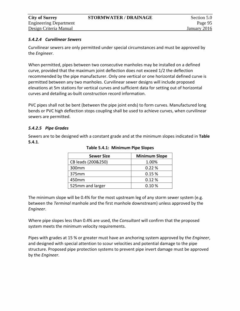
City of Surrey STORMWATER / DRAINAGE Section 5.0 Engineering Department Page 95 Design Criteria Manual January 2016
5.4.2.4 Curvilinear Sewers
Curvilinear sewers are only permitted under special circumstances and must be approved by the Engineer. When permitted, pipes between two consecutive manholes may be installed on a defined curve, provided that the maximum joint deflection does not exceed 1/2 the deflection recommended by the pipe manufacturer. Only one vertical or one horizontal defined curve is permitted between any two manholes. Curvilinear sewer designs will include proposed elevations at 5m stations for vertical curves and sufficient data for setting out of horizontal curves and detailing as‐built construction record information. PVC pipes shall not be bent (between the pipe joint ends) to form curves. Manufactured long bends or PVC high deflection stops coupling shall be used to achieve curves, when curvilinear sewers are permitted. 5.4.2.5 Pipe Grades
Sewers are to be designed with a constant grade and at the minimum slopes indicated in Table 5.4.1.
Table 5.4.1: Minimum Pipe Slopes
Sewer Size Minimum Slope
CB leads (200&250) 1.00%
300mm 0.22 %
375mm 0.15 %
450mm 0.12 %
525mm and larger 0.10 %
The minimum slope will be 0.4% for the most upstream leg of any storm sewer system (e.g. between the Terminal manhole and the first manhole downstream) unless approved by the Engineer. Where pipe slopes less than 0.4% are used, the Consultant will confirm that the proposed system meets the minimum velocity requirements. Pipes with grades at 15 % or greater must have an anchoring system approved by the Engineer, and designed with special attention to scour velocities and potential damage to the pipe structure. Proposed pipe protection systems to prevent pipe invert damage must be approved by the Engineer.
City of Surrey STORMWATER / DRAINAGE Section 5.0 Engineering Department Page 96 Design Criteria Manual January 2016
5.4.2.6 Velocity Requirements
All storm sewers shall be designed to achieve a velocity of 1.0 m/s, however if this cannot be achieved a velocity of at least 0.6 m/s, based on Manning’s Equation full pipe flow, will be achieved. Where design velocities are supercritical or in excess of 3.0 m/s, special provisions shall be made to protect against sewer displacement. The Consultant will provide appropriate analysis and justification and make provisions in the design to ensure that structural stability and durability concerns are addressed. Flow throttling or energy dissipation measures to prevent scour will be required to control the flow velocity or to accommodate the transition back to subcritical flow.
5.4.2.7 Pipe Joints
All concrete pipe joints will be open except where the pipe is temporarily or permanently designed to act under head, when bedding material is river sand, or where infiltration from surrounding soils is not desirable. Appropriately designed sealed pipe joints will be used where the design flow HGL rises above the pipe obvert, or where the pipe backfill may be subject to soil piping. Where “Open Joints” are used, bedding will be 19mm crushed gravel as per the Supplementary Specifications, designed to prevent piping conditions. 5.4.2.8 Recharge
In general, storm sewers will be designed to provide low flow exfiltration to the pipe bedding / backfill and contribute to groundwater recharge. Where groundwater recharge has been designated as desirable and existing surficial and pipe area soils are identified as suitable by a Geotechnical Consultant, additional site specific designed exfiltration systems will be provided.
Conversely, seepage collars or clay plugs will be provided where groundwater may adversely affect steep sewers.
5.4.3 Subsurface Drains
Subsurface drains will be used where supported by a soils report carried out by a qualified Geotechnical Consultant. Subsurface drains located adjacent to roads will be extended well below the road base. The material for subsurface drains will be clear round drain rock in an envelope of approved filter material. A minimum 100mm PVC perforated pipe will be placed at the bottom of the trench.

City of Surrey STORMWATER / DRAINAGE Section 5.0 Engineering Department Page 97 Design Criteria Manual January 2016
5.4.4 Manhole Structures
5.4.4.1 Location
Manholes are required every 150m of storm sewers, for sewers of 900mm diameter or less, and every 300m for sewers larger than 900mm, as well as under the following conditions:
a. At the top end of all Terminal Sewers.
b. Every change of pipe size.
c. Every change of line or grade that exceeds 1/2 the maximum joint deflection recommended by the manufacturer, or where the radius of an approved curvilinear sewer alignment is less than 30m.
d. All sewer confluences and junctions, (except those with interceptor sewers).
e. Sump manhole to be provided immediately upstream of any line feeding to a pump station, siphon or Force Main system.
f. At Service Connection tie‐ins to mains where the Service Connection size is greater than ½ the diameter of the main. and
g. At mains where the Service Connection is 250mm diameter or larger.
Manhole spacing for storm sewers of 1350mm diameter and larger will be evaluated on a site‐specific basis. Temporary cleanouts are permitted where an extension of the sewer, in the future, will provide a manhole at an appropriate spacing. Clean‐outs are not permitted at the Terminal ends of the system. Mid‐block clean‐outs with the foot‐bend pointing uphill are permitted between two manhole structures. Manholes within road right‐of‐ways will be located within the travel Lanes or center median as appropriate, and not closer than 1.5m from the curb. Manhole frames and covers will not be located within a sidewalk unless approved by the Engineer. Where a ditch discharges into a storm sewer system, the initial connecting manhole will be of a sump type as per the Standard Drawings. Unless otherwise directed by the Engineer, ditches discharging into a storm sewer system with 600mm diameter pipes or larger do not require sump manholes. Where a manhole sump is used in lieu of catch basin sumps, the sump manhole will service no more than 5 upstream catch basins. 5.4.4.2 Drop Manhole Structures
Drop manholes, designed in accordance with the Standard Drawings, will only be used when a new incoming sewer cannot be steepened or where site conditions do not permit excavation to the base of an existing manhole.
July 11/16
City of Surrey STORMWATER / DRAINAGE Section 5.0 Engineering Department Page 98 Design Criteria Manual January 2016
Drop manholes are not permitted for sewers 450mm and larger, and not permitted when the depth of the sewer is less than 3.5m. Drop manholes shall be:
a. 1200mm diameter manholes with an inside drop for sewers less than or equal to 300mm diameter, or
b. 1500mm diameter manholes with an inside drop for sewers larger than 300mm,
Outside drop structures, complete with upstream cleanouts for maintenance, may be permitted only if accepted by the Engineer. A straight through ramp drop may be approved by the Engineer. Provision of air vents at intervals along the drop shaft is recommended. These vents should be interconnected by a vent pipe to a manhole above the inlet sewer. 5.4.4.3 Through Manhole Structures
The crown elevations of sewers entering a manhole will not be lower than the crown elevation of the outlet sewer. No drop in invert is required for a through manhole where the sewer mains are of the same size. A 30mm drop in invert for alignment deflections up to 45 degrees and a 60mm drop in invert for alignment deflections from 45 degrees to 90 degrees will be provided. 5.4.4.4 Energy Loss Provisions at Manholes, Junctions and Bends
There is a loss of energy when flow passes through a manhole, junction or bend. These losses can be negligible (e.g. a small diameter sewer flowing partially full at minimum velocities) or substantial (e.g. a large diameter storm sewer flowing full and turning 90 degrees). It is the Consultant’s responsibility to prove, through calculations, that the sewer design has accounted for energy losses.
Major Junctions and Bends For bends and junctions in 675mm diameter sewers or larger, or where flow velocities greater than 2 m/s are anticipated, a detailed analysis is required. Where changes of direction greater than 45 degrees are necessary, the following guidelines apply:
a. The ratio of the bend radius (R), to the pipe’s inside diameter (D) should be greater than 2, where R is measured to the pipe centerline; and
b. Where R/D is less than 2, the maximum bend deflection at one point should be 45 degrees (e.g. use two ‐ 45 degree bends to turn 90 degrees).
Benching at the outside of bends in manholes will be designed to contain the super elevation of flow in the channel.
City of Surrey STORMWATER / DRAINAGE Section 5.0 Engineering Department Page 99 Design Criteria Manual January 2016
Bends in large sewers and flow junctions will be located in separate manholes and multiple flows at a junction manhole will enter an angle less than 180 degrees. Manholes and structures at which flow direction changes occur must be designed with anchorage to resist thrust and impact forces generated by the flow. Special consideration will be given to ensure safe access to these structures. Minor Junctions and Bends Simplified methods are adequate for computing energy losses for junctions and bends involving 600mm diameter sewers and smaller, and sewers with low velocities. The headloss will be calculated as follows: Head Loss (HL) = KL (V0
2/2g)
Where: HL = Head Loss in metres V0 = Average Flow Velocity at bend (m/s) g = Gravitational acceleration (9.81 m/s2) KL = Dimensionless coefficient (refer to Table 5.4.2)
Table 5.4.2: Manhole Head Loss Coefficients (KL)
Deflection Angle
Deflection Flow Channel Characteristics Head Loss
Coefficient (KL)
90º No benching or deflector, or where they only extend up to the springline of the sewer.
KL=1.5
90º Benching or deflector up to the crown of the sewer.
KL=1.0
Less 90º
To determine the head loss coefficient, multiply the head loss coefficient for a 90° bend and the appropriate flow channel type by a head loss ratio factor approved by the Engineer.
For junctions with one or more inlets at or near right angles (90º) to the outlet, the head loss coefficient will vary depending on whether the incoming flow is deflected towards the outlet, or if incoming flows impinge with each other. The following values should be used:
KL = 1.5 impinging flow with no deflector between inlets KL = 1.0 when a deflector is provided between the inlets
City of Surrey STORMWATER / DRAINAGE Section 5.0 Engineering Department Page 100 Design Criteria Manual January 2016
5.4.5 Catch Basins
5.4.5.1 Type and Location
Details of the various approved catch basin structures and components are provided in the Supplementary Specifications and Standard Drawings. Catch basins will be of the grillage‐sump or non‐sump design as per the Standard Drawings. Non‐sump catch basins may be used only where a sump manhole is used in lieu. Catch basins will be provided at regular intervals along roadways, at the upstream end of radius at intersections and at low points (sags). Double catch basins will be used at all low points (sags) and along roadways where higher inlet capture is required. A catch basin will be located to intercept the water flowing in the gutter in advance of a wheelchair ramp, curb letdown or pedestrian crossing. Bicycle friendly top/side inlet style catch basins will be used on all Arterial Roads per the Standard Drawings. 5.4.5.2 Spacing
Catch basin spacing will be based on hydraulic requirements to capture the 5‐year (minor) peak flow. Additional catch basins will be needed if the 100‐year (major) design flows are to be captured and conveyed to the storm sewer system. The Consultant must ensure that sufficient inlet capacity is available to meet the servicing objectives. The capacity of a single catch basin can be calculated using the standard orifice equation, with an orifice coefficient of 0.40, accounting for a clogging factor. Irrespective of the orifice equation, the maximum drainage area to a catchment shall be 500 square meters on road grades up to 3% and 350 square metres on steeper grades. 5.4.5.3 Leads
The catch basin lead size and slope will be based upon hydraulic capacity requirements. Leads will be 200mm in diameter (minimum) for single basins and 250mm (minimum) in diameter for double basins. Double catch basins leads will not be connected directly together but rather one basin lead will “Y” into the lead of the other. 250mm catch basin leads (or larger) should be connected to manholes. The maximum lead length will be 10m, unless otherwise approved by the Engineer.
July 11/16
July 11/16
City of Surrey STORMWATER / DRAINAGE Section 5.0 Engineering Department Page 101 Design Criteria Manual January 2016
5.4.5.4 Frames, Covers and Grates
Side inlet catch basin frames and covers are required for new developments and where a higher inlet capacity is required. These may be installed using 900mm catch basin barrels as appropriate, or may be installed using 1200mm catch basin manholes, as per the Standard Drawings. Catch basin grates are to be set 30mm below the gutter line. The gutter and blacktop are to be shaped to form a dish around the inlet.
5.4.5.5 Lawn Basins
Lawn basins are to be located where significant surface seepage presents hazards for sidewalks, driveways and low properties.
5.4.6 Service Connections
Eligibility requirements for Service Connections to the storm sewer system are outlined in the City’s Stormwater Drainage Regulation and Charges By‐law. Service Connections will be provided to all new lots except park and agricultural lots. Each lot will have:
a. A gravity connection to the frontage sewer; or
b. A gravity connection to the sewer in an open Lane, walkway or service corridor with an access road.
Residential storm Service Connections will meet the following conditions:
a. 150mm minimum diameter;
b. 2.0% minimum grade from property line to storm sewer;
c. 300mm minimum vertical clearance from the 100 year HGL to the MBE of the building; and
d. 500mm minimum vertical clearance above the obvert of the storm sewer to the MBE of the building.
For commercial, industrial and multi‐family properties, the storm service size and grade will be established by the Consultant. Service Connections to industrial, commercial and institutional properties may be permitted from sewers located in easements, provided that the nature of the proposed development will permit access to the easement and excavation as may be necessary for purposes of repair or reconstruction of the Service Connection.
City of Surrey STORMWATER / DRAINAGE Section 5.0 Engineering Department Page 102 Design Criteria Manual January 2016
The Consultant will avoid connecting Service Connections to the main beneath a curb or within a curb return quadrant. Service Connection will be in accordance with the Standard Drawings. All Service Connections should be located 2.0m minimum clear of driveways. Where required by the Engineer, additional Service Connection(s) may be required to isolate foundation drains from other on‐lot drainage components (e.g. lawn basins, detention systems, roof top discharges, etc.). All existing lot drains will be connected to the storm sewer provided that all habitable areas (e.g. MBE) are 300mm above the 100 year (major flow) hydraulic grade line. Storm sewer connections to other utility trenches may be provided where there is a possibility of groundwater concentration. Where the above servicing approach is not possible, the proponent will submit a written proposed alternative to the Engineer for review and approval. The submission will include cross sections and detailed elevation information to support the request. Pumped connections that service industrial buildings may be permitted by the Engineer.
5.4.7 Specialized Structures
5.4.7.1 Inlet and Outlet Structures
Inlet and outlet structures for rural runoff are unique and appropriate consideration must be given to provisions for grates, debris interception, sediment catchment and storage, maintenance and local constraints. Proper rights‐of‐way (e.g. road or utility right‐of‐way) will be required to permit access to inlets and outlets by maintenance equipment and vehicles for maintenance purposes. Rural runoff inlets and outlets may be located within public lands controlled by authorities other than the City with relevant approvals; however, location of inlets and outlets in easements on privately owned property will be permitted only where warranted by special circumstances. Gratings installed over the ends of rural runoff inlets and outlets will be sized with a hydraulic capacity of 200% of the design flow to allow for the effects of blockage or fouling of the grates by debris carried by the flow. Fisheries considerations apply to all structures on creeks classified as “Class A or AO”. Inlet Structure A safety grillage is required at the entrance of every storm sewer or on culverts 450mm diameter or greater which exceed 30m in length.
City of Surrey STORMWATER / DRAINAGE Section 5.0 Engineering Department Page 103 Design Criteria Manual January 2016
A trash screen is required at:
a. The entrance to every storm sewer or culvert less than 450mm diameter, over 30m in length, when the inlet minor flow velocity exceeds 2 m/s;
b. Where there are long runs of natural watercourse, preferably at a road culvert; and
c. No closer than 1.0m from all openings in the culvert.
Outlet Structure Outlets having discharge velocities greater than 1.0m/s require evaluation of the downstream channel. Rip‐rap or an approved energy dissipating structure may be required to control erosion. Generally, structures exceeding 1.2m in height or 2.0m in width shall receive individual structural design. For all outfalls, it is required that a rigorous hydraulic analysis be completed to ensure that the exit velocities to natural watercourses will not produce scour and damage. When sewer discharge is at subcritical flow, then concrete structures with suitable baffles, aprons, and riprap will be acceptable. The exit velocities, where the flow passes from an apron or erosion control medium to the natural channel, will not exceed the flow rates suitable to maintain creek morphology and will be further limited as required based on‐site specific soil and flow conditions. Where high outlet tail water conditions or other downstream conditions may result in the formation of a forced hydraulic jump within the sewer pipe upstream of the outfall, special consideration will be given to the design of that sewer pipe with regard to bedding and structural requirements. Outfall structures are also required at locations where it is necessary to convert supercritical flow to subcritical flow, dissipate the released flow energy, and establish suitably tranquil flow conditions downstream from the sewer outfall.
5.4.7.2 Flow Control Structures
For the design of flow control structures at stormwater storage facilities, riparian diversions, and Trunk Sewer diversions, the orifice and weir equations may be used. Orifice Equation: Q = CA(2gh)0.5
Where: Q = Desired Release Rate (m3/s) A = Area of Orifice (m2) g = Acceleration due to Gravity (m/s2) h = Net Head on the Orifice Plate (m) C = Coefficient of Discharge
City of Surrey STORMWATER / DRAINAGE Section 5.0 Engineering Department Page 104 Design Criteria Manual January 2016
For a sharp or square edged orifice, use a value of 0.62 for the discharge coefficient. The minimum orifice size will be 100mm in diameter. Where smaller orifices are required special provisions are required to prevent blockage. These special provisions will be clearly marked on the design drawings. Weir Equation: Q = CLH1.5
Where: Q = Desired Release Rate (m3/s) C = Coefficient of Discharge L = Effective Length of Crest (m) H = Total Head on Crest (m)
Flow control manholes will be a minimum of 1200mm diameter to provide for access and maintenance. The design of a flow control structure will provide for safe conveyance of overflows and allow maintenance. 5.4.7.3 Safety Provisions
All sewer outlets will be constructed to prevent children or other unauthorized persons from entering the sewer system. Grating, with vertical bars spaced no more than 150mm apart will be installed and fixed in the form of a gate with adequate means for locking in a closed position. Provision for opening or removal of the grate for cleaning or replacing the bars is required. Gratings should be designed to break away under extreme hydraulic loads in the case of blockage. Guard‐rails or fences made of corrosion resistant material will be installed along concrete headwalls and wing walls to provide protection against persons inadvertently falling over the wall.
5.4.7.4 Outfall Aesthetics
Outfalls, which are often located in parks, ravines, or on river banks, should be made aesthetically pleasing and safe. The appearance of these structures is important and cosmetic treatment or concealment is part of the design.
City of Surrey STORMWATER / DRAINAGE Section 5.0 Engineering Department Page 105 Design Criteria Manual January 2016
5.4.8 Culverts
The minimum culvert diameter will be:
a. 300mm for driveway crossings;
b. 600mm for roadway crossings; and
c. Except for Lowland areas where 600mm diameter is the minimum size for both driveway crossings and road crossings.
Driveway culverts will be designed to accommodate the minor flow unless otherwise indicated by the Engineer. Culverts crossing all roads will be designed to accommodate the major flow with either inlet or outlet control. Twin culvert systems are required to reduce constraints where the natural creek width exceeds the single pipe diameter. Surcharging to optimize channel storage is preferred, provided the backwater profile does not encumber properties. On Collector and Local Roads, road overtopping will be permitted only when the backwater profile does not negatively encumber properties. Where road overtopping is anticipated, appropriate scour protection will be provided. All roads will be graded to provide the low point (sag) at the watercourse culvert crossing to provide a fail‐safe major system outlet with limited ponding on the road right‐of‐way. On Arterial Roads, road overtopping will not be permitted and the culverts will be designed to accommodate the major flows, unless under special circumstances, such as floodplain areas, where approved by the Engineer.
5.4.9 Ditches and Swales
Ditches will be designed to convey minor system flows with a minimum 600mm freeboard, except in Lowland areas. Ditches will be trapezoidal in shape having maximum side slopes of 1½ H: 1 V and a minimum bottom width of 0.5m, depending on the soil characteristics. The minimum ditch profile slope will be 0.5%, except in Lowland areas. The maximum velocity in an unlined ditch will be 1.0m/s. Higher velocities may be permitted where soil conditions are suitable or where erosion protection has been provided. On steep slopes, grade control structures may be used to reduce velocities. The ditch right‐of‐way will be sufficiently wide to provide a 3.6 m graded access road suitable for maintenance vehicles, in addition to the width required for the ditch, where the ditch is not adjacent to a municipal roadway
City of Surrey STORMWATER / DRAINAGE Section 5.0 Engineering Department Page 106 Design Criteria Manual January 2016
Swales will be used in road allowances where there is no curb and gutter to direct flow towards catch basins or the storm sewer system. Swales will be used in conjunction with proper lot grading to convey lot runoff and minor flows, as well as to direct major flows within City right‐of‐ways.
Ditches and swales are to be incorporated into road designs, subject to approval by the Engineer.
5.4.9.1 Ditch Infill
Open ditches allow for infiltration of stormwater into the ground helping to recharge groundwater and sustain creek baseflows. In rural areas, the City will not endorse ditch enclosures as rural road cross sections are better serviced through open systems. In much of the City’s lowland floodplain areas, open ditches allow for storage of floodwaters when tides are high or at times of high river levels. Some ditches are channelized fisheries creeks, in which case fisheries considerations will outweigh the request for enclosure of the ditch. Infilling ditches reduces the available storage volume and can impact the hydraulic conveyance capacity of the ditch. The City does not have a ditch enclosure program, and limits infilling existing ditches within the following areas:
a. Bridgeview;
b. Crescent Beach;
c. Serpentine, Nicomekl, and Fraser River floodplains;
d. Campbell River Floodplain;
e. Suburban and Rural properties;
f. Panorama Ridge;
g. All properties within the Agricultural Land Reserve; and
h. Neighbourhood Concept Plan areas where ditches are identified as sustainable drainage features.
Ditch infills may be permitted, subject to the approval of the Engineer, under the following conditions:
a. To provide access to adjacent municipal or private property
b. Safety reasons
c. Ditch is labeled as Class C under the City’s Watercourse Classification System (see Section 5.8)
City of Surrey STORMWATER / DRAINAGE Section 5.0 Engineering Department Page 107 Design Criteria Manual January 2016
Designs must provide compensation for lost storage volume resulting from the ditch infill, and ensure that there is no negative impact to upstream private or municipal property or infrastructure. Water surface profiles and hydraulic grade lines within the ditch in the vicinity of the proposed infill must also be shown on the drawings.
5.4.10 Major Flow Routing
The overland drainage system is comprised of the natural streams and valleys as well as the man‐made streets, swales, channels and ponds, and is generally called the major drainage system. It is the keystone to safe and comprehensive urban drainage, as it accommodates the runoff from more intense and less frequent storms. A properly designed major flow system can greatly reduce the risk of loss of life and property damage due to flooding. All overland flows will have specifically designed flow routes that are protected and preserved by registered easements, restrictive covenants or rights‐of‐way, and the flow routes will convey flows to appropriate safe points of escape or storage. The major flow routing will normally be provided along roads and in natural watercourses. In some cases, the major flow may also be carried alongside the road in grassed swales. Where the road is used to accommodate major flow, it will be formed, graded and sufficiently depressed below the surrounding property lines to provide adequate hydraulic capacity. On Arterial Roads, the 100‐year flow depth will not be higher than centerline of the pavement with the maximum flow depth not to exceed 150mm. On Collector and Local Roads, the entire roadway may be used as a major flood path with the maximum flow depth not to exceed 300mm.
Roadway and other surface features along the major flow path will provide a minimum of 350mm freeboard to the finished ground elevation of buildings on adjacent properties. Overflows will be provided from all sags or depressions such that there will be a minimum freeboard of 150mm from the ground surface elevation at adjacent buildings, and such that the maximum depth of ponding is limited to 350mm. Where major flows pass through intersections, care will be taken to lower the intersection to allow flows to pass over the cross street. Where major flow routes turn at intersections, similar care in the road grading design is required. Major flow surface routes are not permitted between property lines or on easements/rights‐of‐way where public access may be difficult unless approved by the Engineer. Major flow routing will be shown on the stormwater control plans and sufficient design will be carried out to provide assurance to the Engineer that no serious property damage or endangering of public safety will occur under major flow conditions. The discharge point from the development for the major flow route, will be coordinated with the downstream routing to outfalls as determined by the Engineer.
City of Surrey STORMWATER / DRAINAGE Section 5.0 Engineering Department Page 108 Design Criteria Manual January 2016
The use of catch basin inlet control devices to separate major and minor hydraulic grade lines may be allowed subject to the satisfaction of the Engineer regarding the suitability of such control devices. Where catch basin inlet control devices are used, minimum building elevations may be controlled by the resultant hydraulic grade line occurring in the minor system.
The theoretical street carrying capacity can be calculated using the modified Manning’s formula with an “n” value applicable to the actual boundary conditions encountered. Recommended values for n are:
a. 0.018 for roadway; and
b. 0.150 for grassed boulevards.
5.5 Lowland drainage
5.5.1 Level of Service
The drainage objectives and level of service set for these areas come from the ARDSA Program, and the criteria is summarized as:
a. In the growing season (March 1 to November 31), flooding should be restricted to a maximum of 2 days in duration in the 10‐year, 2‐day storm;
b. In the remainder of the year (November 1 to February 28), flooding should be restricted to a maximum of 5 days in duration in the 10–year, 5‐day storm; and
c. Between storms, and in periods when drainage is required, the base flow level in ditches should be maintained at 1.2 m below ground level to provide a free outlet for field drainage.
Any drainage works in the Lowlands will require the review and acceptance by the Engineer in relation to the implementation of the Serpentine‐Nicomekl River lowland flood control project. In addition to the above ARDSA criteria for the Serpentine‐Nicomekl River lowlands, protection of properties from flooding will be provided up to the 200‐year level for areas in the floodplains of the Fraser, Serpentine, Nicomekl and Campbell Rivers. All other areas will be protected from 100‐year flood flows. Filling within the floodplain is governed by the Soil Conservation and Protection By‐law. Filling may be allowed if approved by the Engineer.
City of Surrey STORMWATER / DRAINAGE Section 5.0 Engineering Department Page 109 Design Criteria Manual January 2016
5.5.2 Driveway Culverts
Driveway culverts will have a minimum diameter of 600mm, or as directed by the Engineer. Bedding will consist of 25mm clear crush import material, and will extend to at least the springline of the culvert. The culvert will be backfilled with import granular material, and overlain by the driveway road structure. Native and/or organic material will not be used for culvert bedding or backfill. A non‐woven geotextile will be required around the clear crush bedding. The culvert will be laid on positive grade and oriented to discourage sediment buildup within the culvert. Timber headwalls will be installed at the inlet and outlet ends of the driveway culvert, in accordance with the Standard Drawings. Driveway widths will be as specified in the Standard Drawings. Wider driveways may be approved by the Engineer.
5.5.3 Flood Boxes
New flood boxes through an existing dyke may be required to facilitate drainage. New flood boxes will have a minimum diameter of 600mm (or as directed by the Engineer). Flood boxes will incorporate a flap gate on the river side of the dyke, and be reverse graded to ensure proper seating of the flap gate during high tide conditions. Pressure treated timber support piles will be installed on either side of the flood box and connected above and below the flood box with pressure treated 2x4 wood slats on the river side of the dyke to anchor the flood box in place. At least 1/3 of the total height of the timber support piles will be buried below grade. Flood boxes will be backfilled with structural clay, containing no organics, compacted to 95% Standard Proctor Density (SPD). A non‐woven geotextile may also be required beneath the flood box, as directed by the Consultant or as directed by the Engineer.
5.5.4 Dyke Protection
Infrastructure, utilities and structures, whether publicly or privately owned, will not be installed within the dyke footprint, with the exception of flood boxes and pump stations that provide drainage servicing, where approved by the Engineer and Dyking District. All new structures and utilities must be situated on the land side of the dyke and set back at least 7.5m from the toe of the dyke. Irrigation lines may be situated closer to the toe of the dyke, where approved by the Engineer. Utilities will be located within a dedicated public right‐of‐way. All structures and utilities must be set back at least 7.5m from existing or proposed municipal pump stations and flood boxes through the dyke.
City of Surrey STORMWATER / DRAINAGE Section 5.0 Engineering Department Page 110 Design Criteria Manual January 2016
5.5.5 Drainage Pump Stations
Detailed criteria and specific requirements for drainage pump station facilities should be obtained from, and reviewed with, the Engineer prior to design of the facilities. Good engineering design practice will be used in the design of drainage pump stations. It is recommended that the Consultant refer to the City’s ‐ Guideline for the Design & Construction of Drainage Pump Stations for applicable drainage pump station design criteria. Prior to commencing the detailed design of a pump station, the Consultant will confirm the catchment areas, design flows and the proposed location of the pump station with the Engineer. The Consultant will submit a pre‐design report that addresses the requirements given in this Manual and the Guideline for the Design & Construction of Drainage Pump Stations for approval by the Engineer. Private drainage pump stations may be permitted if approved by the Engineer.
5.6 Water Quality Treatment
5.6.1 Oil / Grit Separator
An oil / grit separator capable of removing coarse sediments and capturing oil from surface runoff will be installed to serve parking lots, multi‐unit residential, commercial, institutional and industrial sites, as well as any other hard surfaces as directed by the Engineer. See the Standard Drawings for a typical layout of oil / grit separator. The primary settling portion of the unit will have a hydraulic loading rate (HLR), at the design discharge rate, of less than or equal to 0.027 m3/s/m2. The HLR will be calculated as follows: HLR = QWQ / AS,
Where: QWQ = water quality treatment design discharge (70% of the 2‐year frequency
discharge at duration equal to the site’s Time of Concentration (TC)), in cubic metres per second (m3/s);
AS = surface area of treatment portion of the oil / grit separator, defined as the area where sediment and oil are captured, in square metres (m2).
At the target HLR, the unit will be capable of settling coarse particles of D50 > 0.115mm at 5 C and specific gravity of 2.65, and capturing free oil droplets of D50> 0.465mm at 5 C and assuming a specific gravity of 0.88 for a “typical” motor oil. The target effluent shall meet ESC Bylaw requirements and a TSS removal rate of 85%.
City of Surrey STORMWATER / DRAINAGE Section 5.0 Engineering Department Page 111 Design Criteria Manual January 2016
At a minimum, the following structural components will be included with all proposed systems:
a. Provide a minimum sediment storage depth of 0.25m;
b. Provide a minimum oil storage depth of 0.05m;
c. Provide a minimum total pool depth of 1.00m;
d. Provide baffles and skimmers to prevent re‐suspension and loss of sediment and oil; and
e. Provide either an internal bypass or an external bypass to limit flows through the treatment compartment(s) to the design discharge rate (QWQ).
5.6.2 Coalescing Plate Oil Separator
Where requested by the Engineer, at sites likely to generate high concentrations of oil for sustained periods (generally > 20 mg/L) such as gasoline service stations, vehicle maintenance yards, and industrial areas, a coalescing plate oil separator will be installed. These units are oil / grit separators with the addition of coalescing plate packs to significantly enhance oil capture capabilities. The oil treatment chamber of the unit will have a hydraulic loading rate (HLR), at the design discharge rate, of less than or equal to 1.06 x 10‐3 m3/s/m2. The HLR will be calculated as follows: HLR = QWQ / AP
Where: QWQ = design discharge rate (70% of the 2‐year frequency discharge at duration
equal to the site’s Time of Concentration (TC)), in cubic metres per second (m3/s); and
AP = total projected horizontal surface area of the coalescing plates, in square metres (m2), calculated as AP = A x (cos H), where A is the surface area of the coalescing plates and H is the angle of the plates to the horizontal.
At the target HLR, the unit will be capable of capturing and removing free oil droplets with D50
greater than or equal to 0.050mm at 5 C and assuming a specific gravity of 0.88 for a “typical” motor oil. The target effluent oil concentration will be ≤ 10 mg/l.
City of Surrey STORMWATER / DRAINAGE Section 5.0 Engineering Department Page 112 Design Criteria Manual January 2016
At a minimum, the following structural components will be included with all proposed systems:
a. Install off‐line, with external bypass provided for flows greater than QWQ;
b. Plates not less than 16 mm apart;
c. Provide a forebay or other form of pre‐treatment to remove course sediment and debris; if a forebay within the unit is used, provide a baffle to prevent sediments from entering the coalescing plate pack compartment;
d. Provide a minimum sediment storage depth of 0.25m;
e. Provide a minimum oil storage depth of 0.05m;
f. Provide baffles and skimmers to prevent oil loss; and
g. Provide a shut‐off valve on the outlet pipe.
5.6.3 Operation and Maintenance Considerations
As part of the Engineering Drawing submission, the Consultant shall provide an operation and maintenance (O&M) manual that summarizes the operation and maintenance requirements for water quality treatment units incorporated into the design. The O&M manual is to include, but is not necessarily limited to, the following:
a. Manufacturer’s operation and maintenance information, if using a commercially manufactured unit.
b. An emergency spill abatement plan specific to the site.
c. Schedules, timing and procedures for removal and proper disposal of captured sediment and oil.
d. Procedures for taking unit offline for maintenance, reactivating unit following maintenance.
e. Procedures for providing flow conveyance and treatment of runoff while unit is offline for maintenance.
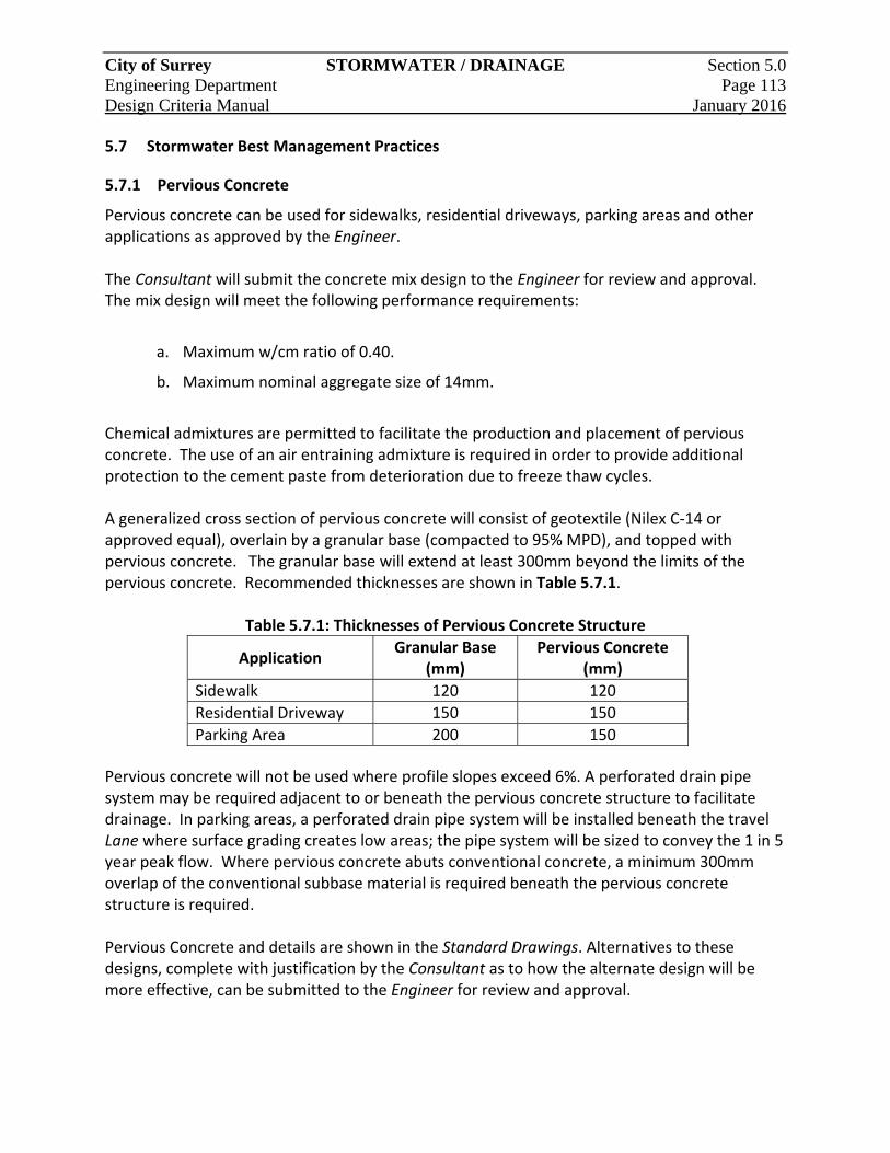
City of Surrey STORMWATER / DRAINAGE Section 5.0 Engineering Department Page 113 Design Criteria Manual January 2016
5.7 Stormwater Best Management Practices
5.7.1 Pervious Concrete
Pervious concrete can be used for sidewalks, residential driveways, parking areas and other applications as approved by the Engineer. The Consultant will submit the concrete mix design to the Engineer for review and approval. The mix design will meet the following performance requirements:
a. Maximum w/cm ratio of 0.40.
b. Maximum nominal aggregate size of 14mm.
Chemical admixtures are permitted to facilitate the production and placement of pervious concrete. The use of an air entraining admixture is required in order to provide additional protection to the cement paste from deterioration due to freeze thaw cycles. A generalized cross section of pervious concrete will consist of geotextile (Nilex C‐14 or approved equal), overlain by a granular base (compacted to 95% MPD), and topped with pervious concrete. The granular base will extend at least 300mm beyond the limits of the pervious concrete. Recommended thicknesses are shown in Table 5.7.1.
Table 5.7.1: Thicknesses of Pervious Concrete Structure
Application Granular Base
(mm) Pervious Concrete
(mm)
Sidewalk 120 120
Residential Driveway 150 150
Parking Area 200 150
Pervious concrete will not be used where profile slopes exceed 6%. A perforated drain pipe system may be required adjacent to or beneath the pervious concrete structure to facilitate drainage. In parking areas, a perforated drain pipe system will be installed beneath the travel Lane where surface grading creates low areas; the pipe system will be sized to convey the 1 in 5 year peak flow. Where pervious concrete abuts conventional concrete, a minimum 300mm overlap of the conventional subbase material is required beneath the pervious concrete structure is required. Pervious Concrete and details are shown in the Standard Drawings. Alternatives to these designs, complete with justification by the Consultant as to how the alternate design will be more effective, can be submitted to the Engineer for review and approval.

City of Surrey STORMWATER / DRAINAGE Section 5.0 Engineering Department Page 114 Design Criteria Manual January 2016
5.7.2 Porous Asphalt
Porous asphalt can be used for residential driveways, lightly travelled portions of parking areas, and other applications as approved by the Engineer. The Consultant will submit the material gradations and asphalt mix designs to the Engineer for review and approval. Examples of the choker and reservoir course gradations and porous asphalt mix design can be provided to the Consultant by the Engineer on request. The choker and reservoir course materials will meet the following performance requirements:
a. Maximum wash loss of 0.5%;
b. Minimum durability index of 35; and
c. Maximum abrasion loss of 10% for 100 revolutions, and maximum of 50% for 500 revolutions.
A generalized cross section of porous asphalt will consist of a geotextile (Nilex C‐14 or approved equal), overlain by a reservoir course, overlain by a choker course and topped with porous asphalt. The choker and reservoir courses will be compacted to 95% MPD. Recommended thicknesses are shown in Table 5.6.2 below.
Table 5.6.2: Recommended Thicknesses of Porous Asphalt Structure
Application Reservoir
Course (mm) Choker Course
(mm) Porous Asphalt
(mm)
Residential Driveway 150 to 450 100 100
Parking Area 150 to 450 100 100
Porous asphalt will not be used where profile slopes exceed 6%. A perforated drain pipe system may be required adjacent to or beneath the porous asphalt structure to facilitate drainage. In parking areas, a perforated drain pipe system will be installed beneath the travel Lane where surface grading creates low areas; and the pipe system will be sized to convey the 1 in 5 year peak flows. Porous asphalt and details are shown in Standard Drawings. Alternatives to these designs, complete with justification by the Consultant as to how the alternate design will be more effective, can be submitted to the Engineer for review and approval.
City of Surrey STORMWATER / DRAINAGE Section 5.0 Engineering Department Page 115 Design Criteria Manual January 2016
5.7.3 Absorbent Topsoil
Absorbent topsoil can be used within all pervious areas within the development. Topsoil composition should meet or exceed the growing medium requirements in the Supplementary Specifications. The topsoil depth should range between 150mm to 600mm, depending on the design objectives and volume of water to be retained. Topsoil surface grades should not exceed 2% unless additional methods are implemented to prevent surface erosion and rilling. If the native subgrade has infiltration rates below 0.5mm/hr, the use of subdrains should be considered to prevent oversaturation of the absorbent topsoil. Absorbent topsoil details are shown in the Standard Drawings. Alternatives to this design, complete with justification by the Consultant as to how the alternate design will be more effective in capturing and retaining, can be submitted to the Engineer for review and approval.
5.7.4 Water Quality Dry Swale
Swale systems where approved by Engineer can be incorporated into road and parking lot designs to provide water quality treatment. Water quality swales are typically utilized at the start of a rainfall event, capturing and treating flows up to the design flow before overflowing into an alternate conveyance system; otherwise, they are dry. The following performance criteria should be targeted at a minimum for the design flow:
a. Maximum water velocity : 0.5 m/s
b. Maximum water depth: 400mm
The swale will be at least 600mm wide at the base, with 3 H: 1V maximum side slopes. Swales will have a profile slope no steeper than 4%, although the use of check dams or alternative gradient structures or approaches can be considered. A freeboard depth of 150mm will be incorporated. Swales will be planted with native grass and/or wild flower mixture, underlain by 150 to 300mm of absorbent topsoil. Temporary erosion protection may be required until the planting is adequately established. A typical water quality swale details is shown in the Standard Drawings. Alternatives to this design, complete with justification by the Consultant as to how the alternate design will provide a higher level of water quality treatment, can be submitted to the Engineer for review and approval.
For water quality dry swales, the grass height should be at least 300mm high, but no more than 750mm high, to provide optimum contact area and treatment without negatively impacting the conveyance properties of the swale.
City of Surrey STORMWATER / DRAINAGE Section 5.0 Engineering Department Page 116 Design Criteria Manual January 2016
5.7.5 Infiltration Trench
Infiltration trenches are subsurface linear BMPs that aim to reintroduce stormwater runoff back into the subgrade soils near the source point. They can be applied in a number of land‐use situations, however, pre‐treatment may be required if there is concern about contaminants in the runoff, as may be the case for industrial, commercial or institutional land‐uses. Infiltration trenches will be at least 1.0m wide and 1.2 to 2.0m deep, with the length necessary to achieve the storage and infiltration objectives. A non‐woven geotextile will be laid around the infiltration trench, and the trench will be filled with 25‐75mmØ clear crush gravel. The top of the trench will be approximately 150 to 300mm below ground surface to minimize long‐term clogging of the main stone gallery with sediment. Infiltration trenches will be topped with a grass filter strip that is at least 5m wide, graded at 2% maximum. A 150mm diameter vertical perforated pipe, capped at the surface of the infiltration trench, will be installed near the middle of the trench for access and observation of water levels within the subsurface stone gallery. If the native subgrade has infiltration rates below 0.5mm/hr, the use of subdrains and/or an overflow should be considered.
A typical infiltration trench detail is shown in the Standard Drawings. Alternatives to this design, complete with justification by the Consultant as to how the alternate design will be more effective, can be submitted to the Engineer for review and approval.
5.7.6 Operation and Maintenance Considerations
As part of the Engineering Drawing submission, the Consultant will provide an operation and maintenance (O&M) manual that summarizes the operation and maintenance requirements for BMPs incorporated into the design. The O&M manual will include, but is not necessarily limited to, the following:
a. Summary of annual O&M requirements for all BMP components;
b. Flushing, sweeping and/or cleaning techniques, including timing schedule, for BMPs such as perforated drain pipe systems, pervious concrete, porous asphalt, etc.; and
c. Plant species list, including seasonal maintenance requirements and identification of aesthetic versus compensation plantings.
City of Surrey STORMWATER / DRAINAGE Section 5.0 Engineering Department Page 117 Design Criteria Manual January 2016
5.8 Storage Facility Design
5.8.1 Facility Types
When reviewing stormwater management alternatives, the storage methods described below should be considered, as well as other methods of merit which the Consultant may determine. The optimum number, type(s) and location(s) of stormwater storage facilities must be determined to develop the most economically feasible and effective drainage system.
5.8.1.1 Wet Ponds
Wet ponds collect runoff generated and store it for a significant period, and then release the runoff at a controlled rate. Wet ponds incorporate a permanent water level known as the permanent pool, which rises in response to a storm event then returns to its original elevation after runoff is released. Wet ponds often incorporate recreational or aesthetic uses such as walking paths and viewpoints. As well, water quality related benefits should be achieved by extending the storage duration for the more frequent runoff from the watershed.
5.8.1.2 Dry Ponds
Dry ponds are typically used to control larger, less frequent flows, while allowing low flows to pass through uncontrolled. Dry ponds do not have a permanent pool. In general, they remain dry until the design inflow is reached and the pond’s outlet control structure is triggered. The outlet structure restricts the outflow rate, causing the excess runoff to be temporarily detained.
5.8.1.3 Constructed Wetlands
Constructed wetlands are particularly useful where, in addition to reducing peak outflow rates, improving water quality is an important consideration. In addition to providing water quality treatment, wetlands can also provide enhanced aquatic and terrestrial habitat.
5.8.2 Facility Location
In general, site selection for stormwater storage facilities is governed by the watershed topography, natural drainage conveyance and confluence locations, receiving watercourse location, and constraints imposed by the proposed development. If feasible, storage facilities should be sited in conjunction with other park, sports fields or common community facilities to enhance their visual and environmental benefits as well as to minimize costs through sharing the land requirements. The location of stormwater storage facilities within parks and/or school sports fields requires close consultation with the public, Parks Board, School Board, etc.
City of Surrey STORMWATER / DRAINAGE Section 5.0 Engineering Department Page 118 Design Criteria Manual January 2016
5.8.3 General Design Requirements
Stormwater storage facilities will be designed to satisfy the servicing objectives stated in Section 5.2 with the ability to accommodate flows from the ultimate contributing drainage area under future development conditions.
Hydraulic performance requirements, including storage capacity, discharge requirements, draw down rates, freeboard requirements, and other basic design, will be calculated to meet the objectives set out in the applicable area drainage studies, ISMP’s and according to current best practices for flood, erosion and sediment control. When computing the detention storage requirements for a given event, the lowest 0.2 m depth of the pond above the controlled outflow pipe’s invert will be excluded, as this depth is usually taken up by stormwater runoff preceding a design storm event. 5.8.3.1 Land Dedication and Easement Requirements
The requirement for dedication of land on which a stormwater pond is situated will be in accordance with the policy established by the Engineer, as may be revised from time to time. A Statutory Right‐of‐Way will be designated to cover the following:
a. Access to and from the pond, including maintenance access routes;
b. Pond surface area at the design high water level (typically 100 year), plus the landscaped edge treatment surrounding the pond; and
c. Inlet, outlet and flow control structures, including sewers leading to and from those structures.
A restrictive covenant and/or a limit for the Minimum Building Elevation (MBE) will be placed upon those lots abutting the pond, such that the design requirements of the stormwater storage facility are not compromised and an adequate freeboard is maintained. 5.8.3.2 Geotechnical Considerations
Final designs for stormwater storage facilities will include investigations to address groundwater table interaction, as well as the permeability, composition and stability of the in‐situ soils.
5.8.3.3 Outlet Controls
The outlet from a stormwater storage facility must incorporate appropriate means for flow control to limit the rate of discharge. In addition, the outlet structure must include provisions for operational flexibility and access for maintenance purposes. The Standard Drawings show typical outlet control structures for a stormwater storage facility.
City of Surrey STORMWATER / DRAINAGE Section 5.0 Engineering Department Page 119 Design Criteria Manual January 2016
5.8.3.4 Overflow Provisions
An overflow spillway will be provided for each storage facility. The Consultant will identify the probable frequency of operation of the overflow spillway. The spillway design will consider the possible consequences of blockage of the system outlet or overloading due to consecutive runoff events, such that the storage capacity of the facility may be partially or completely unavailable at the beginning of a runoff event. Since storage facilities are generally designed to attenuate peak flows up to the 5‐year level, if it is not feasible to provide overflow spillway(s) from the storage facility during larger events, an alternate design must be provided for the safe conveyance of excess flows to receiving watercourses.
5.8.3.5 Protection of Riparian Areas
Where proposed storage facilities will abut natural riparian areas, additional measures (such as fencing) may be required to protect the riparian area. The Consultant will refer to the City’s Parks, Recreation and Culture Standard Construction Documents, March 2006, and the Engineer for further guidance.
5.8.3.6 Signage for Safety
Stormwater management facility designs will include adequate provisions for installation of standard signage to warn of anticipated water level fluctuations, with demarcation of the expected maximum water levels for design conditions. Warning signs for thin ice conditions, safety, etc. will be provided and installed by the City.
5.8.3.7 Staged Construction ‐ Standards for Interim Storage Facilities
The City’s aim is to have community stormwater storage facilities located in their ultimate locations from the start of the development, even if they are constructed on a staged basis. Land requirements must be secured for the ultimate facility size, accounting for any external contributing drainage areas that may be developed in the future. When stormwater storage facilities are to be implemented in stages, the interim facility will be designed in accordance with this Manual. Any proposal for application of alternative standards will require approval from the Engineer. All‐weather vehicle access routes must be provided to all pond outlet control structures and works, as well as to the edge of all stormwater management ponds (for use as a boat launch point). Routes must be suitable to carry maintenance vehicles. The access route surface will be a minimum of 4.0m wide, will extend into the pond beyond the pond edge at normal water depth to a point where the normal water depth is 1.0m, and will be accessible from and extend to a public road right‐of‐way. Sharp bends in this access route are to be avoided.

City of Surrey STORMWATER / DRAINAGE Section 5.0 Engineering Department Page 120 Design Criteria Manual January 2016
5.8.3.8 Engineering Drawing Requirements
The engineering drawings for design of a new, or modifications to an existing, stormwater storage facility are to include the following information, in addition to the physical dimensions, in a format similar to Table 5.8.1:
a. Stage‐volume / area / discharge curves for 2, 5, and 100‐year level storms;
b. Elevations, Volumes and Areas at: NWL, 5‐Year Level, Freeboard Level;
c. Note indicating the lowest allowable building elevation for lots abutting the pond;
d. Contributing basin size (ha) and catchment plan;
e. Measurements to locate submerged inlets(s), outlet(s) and sediment traps referenced to structures which are not submerged at the NWL;
f. Erosion and Sediment Control provisions which satisfy the ESC By‐law; and
g. Landscaping plans, for both wet and dry ponds.
Table 5.8.1: Pond Data Summary
Name: GIS ID:
Location: Type:
Contributing Catchment: (Ha)
Inlets and Outlets:
Location: Size Invert Elev.
Allowable 5‐year Outflow Rate: Controlled 5‐year Outflow Rate:
LEVEL LOCATION SIZE (ha) (surf. area)
ELEVATION(m)
VOLUME(m3)
DEPTH (m)
DISCHARGE(m3/s)
BOTTOM
NWL *
1:2‐YEAR
1:5‐YEAR
1:100‐YEAR
HWL *
EMBANKMENT TOP
City of Surrey STORMWATER / DRAINAGE Section 5.0 Engineering Department Page 121 Design Criteria Manual January 2016
5.8.4 Wet Pond Design Details
5.8.4.1 Minimum Pond Size
The minimum catchment area of any pond will be 20 ha. The storage size will be determined based on the outflow control requirements.
5.8.4.2 Side Slopes and Depth
Side slopes and minimum depth requirements are shown on the Standard Drawings. Proposals to amend the slope requirements will be reviewed and approved by the Engineer on a site specific basis.
5.8.4.3 Pond Bottom Material
For areas where the groundwater table is below the NWL, the pond bottom and side slopes are to be composed of impervious material with a suitably low permeability (e.g. with a permeability coefficient in the order of 1 x 10‐6 cm/s). For areas where the groundwater table is expected to be near or above the NWL, the pond bottom and side slopes may be composed of pervious material as dictated by a geotechnical Consultant.
5.8.4.4 Inlet and Outlet Requirements
Inlets and outlets should be situated to maximize detention time and circulation within the pond, while avoiding the potential for narrow and/or stagnant areas to develop. Inlet and outlet pipe inverts are to be a minimum 0.1 m above the pond bottom. Forebays are to be constructed on the pond bottom as required to achieve sufficient depth for placing inlet/outlet structures, and provide sediment deposition. 5.8.4.5 Inlet Sewer to Pond
The invert elevation at the first manhole upstream from the pond will be at or above the normal water level of the pond to avoid deposition of sediments in the inlet sewer. To avoid backwater effects on the upstream sewers, the crown of the inlet sewer at the first manhole upstream from the pond will be at or above the corresponding pond water level for the 1 in 5‐year storm. When the above cannot be achieved due to grading limitations, special maintenance needs, such as periodic flushing/cleaning must be identified.
5.8.4.6 Provisions for Water Level Measurements
To permit the direct measurement of water levels in the pond, a manhole will be provided that is hydraulically connected to the pond, such that the water level in the manhole will mimic the pond water surface level at any given time.
City of Surrey STORMWATER / DRAINAGE Section 5.0 Engineering Department Page 122 Design Criteria Manual January 2016
5.8.4.7 Provisions for Lowering the Pond Water Level
The ability to drain the pond completely by gravity is desirable. Where a gravity drain is not feasible, provisions are to be made as part of the outlet works (or otherwise) so that mobile pumping equipment may be installed and used to drain the pond.
5.8.4.8 Sediment Removal Provisions
The pond design will include an approved sediment removal process for control of heavy solids which may be washed to the pond during the construction period associated with the development of the contributing basin. Sediment basins will be provided at all inlet locations for continued use after completion of the subdivision development. Stormwater storage/detention ponds will not take the place of a development’s sediment control storage basin.
5.8.4.9 Pond Edge Treatment and Landscaping
Edge treatment or shore protection is required and will be compatible with the adjacent land‐use. The treatment used will meet criteria for low maintenance, safety and habitat requirements. The edge treatment will cover ground surfaces exposed or covered by water during a pond level fluctuation that is 0.3m below or above the NWL. The typical acceptable edge treatment will be, but is not limited to, a 250mm deep layer of well graded washed rock with a 75mm minimum diameter or alternatively appropriate vegetation. The proposal of variations to the edge treatment minimum is encouraged, with the final selection of edge treatment being subject to approval from the Engineer. Landscaping of all proposed public lands and easements dedicated for the facility, including all areas from the pond edge treatment up to the NWL is to be part of the pond design. Landscaping plans will clearly identify aesthetic versus compensation plantings. The minimum requirement for landscaping, beyond the edge treatment, will be the establishment of grass cover.
City of Surrey STORMWATER / DRAINAGE Section 5.0 Engineering Department Page 123 Design Criteria Manual January 2016
5.8.5 Dry Pond Design Details
The design details should follow those given for wet ponds with specific modifications as outlined below.
5.8.5.1 Frequency of Operation
All dry ponds will consist of off‐line storage areas designed to temporarily detain excess runoff and thereby reduce the peak outflow rates to the connected downstream system. These facilities may be subject to prolonged inundation during winter months.
5.8.5.2 Side Slopes and Depth
Side slopes within the limits to inundation (e.g. upon filling of the dry pond) will have a maximum slope of 4 (horizontal) to 1 (vertical) within public property, as shown on the Standard Drawings. The maximum live storage depth in a dry pond is 3.0m for the 100‐year event and 1.5m for the 5‐year event, as measured from the invert elevation of the outlet pipe.
5.8.5.3 Bottom Grading and Drainage
The dry pond will be graded to properly drain all areas after its operation. The dry pond bottom will have a minimum slope of 0.5%, however, a slope of 0.7% or greater is recommended. Lateral slopes for the pond bottom will be 0.5% or greater. French drains or similar means may be required where it is anticipated that these slopes will not properly drain the dry pond bottom, or where the land dedicated for the dry pond is used by others when the pond is not activated (e.g. as a recreational field), or other special considerations.
5.8.5.4 Safety Provisions at Inlets and Outlets
All inlet and outlet structures associated with dry ponds will have grates installed over their openings to restrict access and prevent entry into sewers. A maximum clear bar spacing of 0.15m will be used for gratings. Grated outlet structures will be designed with a hydraulic capacity of at least twice the required capacity to allow for possible blockage and plugging. Further, the arrangement of the structures and the location of the grating will be such that the velocity of the flow passing through the grating will not exceed 1.0 m/s. Appropriate fencing and guard‐rails will be provided to restrict access.
5.8.6 Maintenance and Service Manual
The Consultant will prepare an Operation and Maintenance (O&M) Manual for the storage facility along with As‐Constructed drawings following construction. Two (2) complete copies of the manual and a consolidated digital copy (PDF) are to be provided to the Engineer prior to the time when the operation responsibility of the facility is transferred to the City. A digital copy of the manual and As‐Constructed drawings will also be provided. This manual will include a complete list of equipment; the manufacturer’s operation,
City of Surrey STORMWATER / DRAINAGE Section 5.0 Engineering Department Page 124 Design Criteria Manual January 2016
maintenance, and service repair instructions; and complete parts lists for any mechanized or electrical equipment. The manual will also include, at minimum, the following information:
a. A completed Pond Data Summary (see Table 5.8.1) for the storage area, elevation, and outlet control characteristics of the pond;
b. Schematic diagrams of the inlet and outlet arrangements, connection to and arrangement of upstream and downstream systems, including all controls, shutoff valves, bypasses, overflows, and any other operation or control features;
c. Location plans for all operating devices and controls, access points and routes, planned overflow routes, or likely point of overtopping in the case of exceedance;
d. Stage‐Area‐Storage and Stage‐Discharge Curves;
e. Stage‐Discharge relationships for downstream storm sewers or channels, with indication of backwater effects which may restrict the outflow;
f. Outline the expected operational requirements and costs for the facility;
g. An outline of the emergency operating requirements under possible abnormal situations;
h. Information/data sheets to document post‐construction monitoring expectations; and
i. Plant species list for edge treatment and the area surrounding the pond, including identification of aesthetic versus compensation plantings, and maintenance requirements.
5.9 Watercourse Design
The City’s storm drainage conveyance system consists of two main components: the closed conduits (sewers, manholes and outfalls) and the open conduits (ditches, creeks, watercourses, culverts, bridges, and rivers). The open conduits form a major part of the total drainage conveyance system and can be consolidated under the generic term “watercourses” for the purposes of this discussion. Watercourses have the dual function of safely conveying runoff as well as providing sustainable habitat for aquatic and terrestrial life. The ability of the watercourses to perform these functions in perpetuity must be protected.
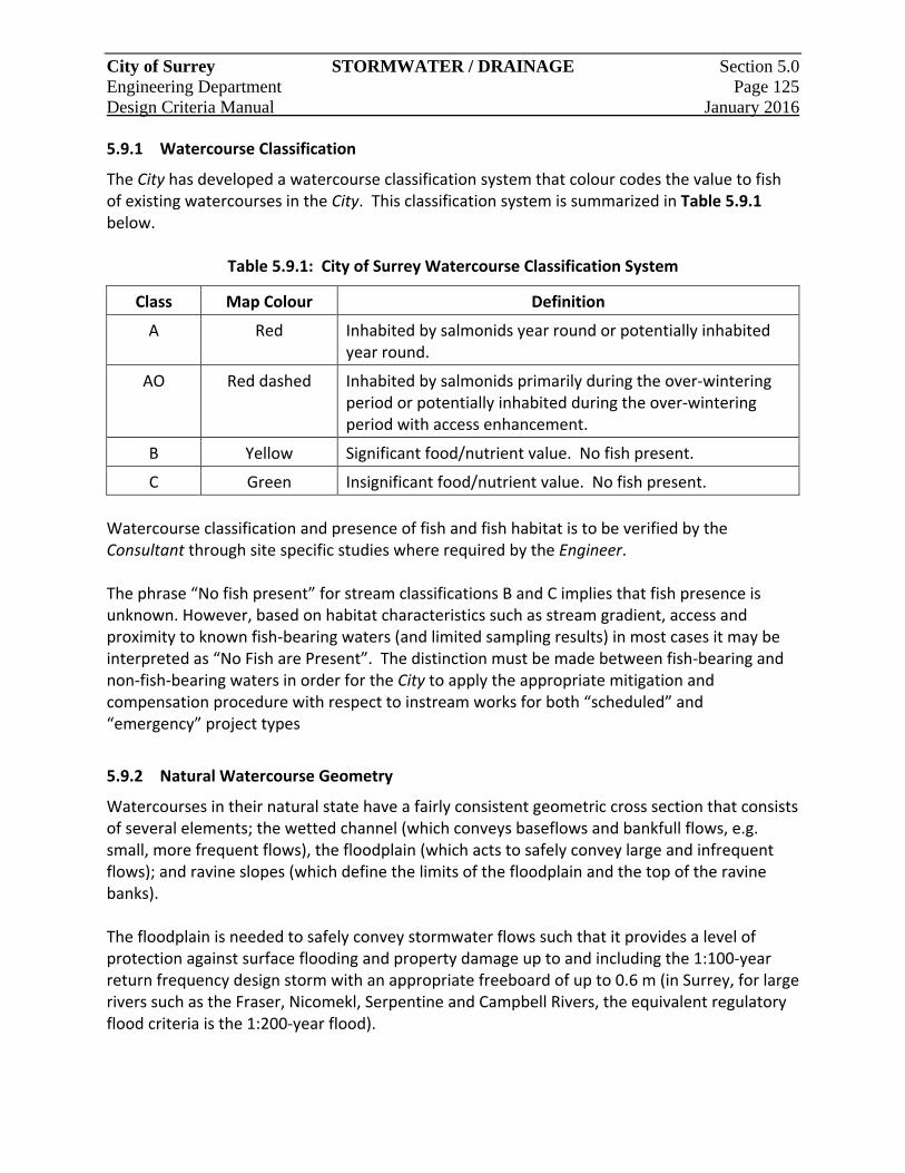
City of Surrey STORMWATER / DRAINAGE Section 5.0 Engineering Department Page 125 Design Criteria Manual January 2016
5.9.1 Watercourse Classification
The City has developed a watercourse classification system that colour codes the value to fish of existing watercourses in the City. This classification system is summarized in Table 5.9.1 below.
Table 5.9.1: City of Surrey Watercourse Classification System
Class Map Colour Definition
A Red Inhabited by salmonids year round or potentially inhabited year round.
AO Red dashed Inhabited by salmonids primarily during the over‐wintering period or potentially inhabited during the over‐wintering period with access enhancement.
B Yellow Significant food/nutrient value. No fish present.
C Green Insignificant food/nutrient value. No fish present.
Watercourse classification and presence of fish and fish habitat is to be verified by the Consultant through site specific studies where required by the Engineer. The phrase “No fish present” for stream classifications B and C implies that fish presence is unknown. However, based on habitat characteristics such as stream gradient, access and proximity to known fish‐bearing waters (and limited sampling results) in most cases it may be interpreted as “No Fish are Present”. The distinction must be made between fish‐bearing and non‐fish‐bearing waters in order for the City to apply the appropriate mitigation and compensation procedure with respect to instream works for both “scheduled” and “emergency” project types
5.9.2 Natural Watercourse Geometry
Watercourses in their natural state have a fairly consistent geometric cross section that consists of several elements; the wetted channel (which conveys baseflows and bankfull flows, e.g. small, more frequent flows), the floodplain (which acts to safely convey large and infrequent flows); and ravine slopes (which define the limits of the floodplain and the top of the ravine banks). The floodplain is needed to safely convey stormwater flows such that it provides a level of protection against surface flooding and property damage up to and including the 1:100‐year return frequency design storm with an appropriate freeboard of up to 0.6 m (in Surrey, for large rivers such as the Fraser, Nicomekl, Serpentine and Campbell Rivers, the equivalent regulatory flood criteria is the 1:200‐year flood).
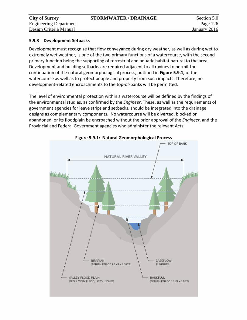
City of Surrey STORMWATER / DRAINAGE Section 5.0 Engineering Department Page 126 Design Criteria Manual January 2016
5.9.3 Development Setbacks
Development must recognize that flow conveyance during dry weather, as well as during wet to extremely wet weather, is one of the two primary functions of a watercourse, with the second primary function being the supporting of terrestrial and aquatic habitat natural to the area. Development and building setbacks are required adjacent to all ravines to permit the continuation of the natural geomorphological process, outlined in Figure 5.9.1, of the watercourse as well as to protect people and property from such impacts. Therefore, no development‐related encroachments to the top‐of‐banks will be permitted. The level of environmental protection within a watercourse will be defined by the findings of the environmental studies, as confirmed by the Engineer. These, as well as the requirements of government agencies for leave strips and setbacks, should be integrated into the drainage designs as complementary components. No watercourse will be diverted, blocked or abandoned, or its floodplain be encroached without the prior approval of the Engineer, and the Provincial and Federal Government agencies who administer the relevant Acts.
Figure 5.9.1: Natural Geomorphological Process

City of Surrey STORMWATER / DRAINAGE Section 5.0 Engineering Department Page 127 Design Criteria Manual January 2016
5.9.4 General Design Requirements
Table 5.9.2 below summarizes the various analyses to be undertaken as part of the process of designing a natural channel.
Table 5.9.2: Natural Channel Design Analysis
Purpose Analysis Criteria Method
Hydrology Estimate flows Regulatory Riparian Bank Full Low Flows (Base Flows)
Local data Regional data Model analysis
Stream hydraulics Estimate velocities, forces, timing
Erosion, fish habitat Estimate energy and water surface profile
Channel geometry
Relate channel and flow conditions
Width, depth, slope, substrate
Field data and hydraulic analysis
Fish habitat Identify existing and potential habitat conditions
Depth, velocity, sediment, water quality
Relate hydrology, hydraulic, and channel geometry with fish habitat requirement
Watercourse designs must conform to the findings and recommendations of the various design studies and reports, including the applicable ISMPs, NCPs and MDPs. In all cases, including those for which specific background information is not available, the Consultant must initially confirm with the Engineer the design requirements and develop the design solutions to ensure that latest relevant data and information are used for the required analytical work. The Consultant will also refer to the relevant Municipal Provincial and Federal Statutes, By‐laws, Policies and Guidelines when designing watercourses and watercourse protection. It is the Consultant’s responsibility to confirm which agencies are required to provide formal review and approval. Detailed site specific surveys, investigations, analysis and design are required to fully and properly assess and evaluate watercourse constraints and functional characteristics for a full range of issues such as flow conditions, top‐of‐bank definition, bed and bank protection and habitat protection.
5.9.5 Design Details
Use of open conduits as part of the drainage system has significant advantages in regard to cost, capacity, multiple use for recreational and aesthetic purposes, and potential for transitory detention storage. Disadvantages include right‐of‐way needs and maintenance costs. Careful planning and design are needed to minimize the disadvantages and to increase the benefits.
City of Surrey STORMWATER / DRAINAGE Section 5.0 Engineering Department Page 128 Design Criteria Manual January 2016
Any proponent designing new or instream works within Surrey needs to have design criteria and plans reviewed by Engineer as all streams play a role in the overall City drainage system. 5.9.5.1 Channel Geometry
The geometric stability of a natural drainage channel is a complex issue as it depends on the magnitude of the fluvial hydraulic forces generated by a dynamic, interactive process involving a number of hydrologic, hydraulic and morphologic variables. Therefore, a natural channel must be carefully studied to determine what cost effective measures are needed so as to control future bottom scour and bank undercutting and preserve the natural appearance while functioning properly. Channel geometry must be based on a variety of multi‐disciplinary factors and complex considerations, including:
a. Hydraulic
watercourse slope, topography, and surface soils;
right‐of‐way and capacity needed;
ability to drain adjacent lands;
basin sediment yield; and
Forces (curvature impacts, changes in cross section, backwater and hydraulic jumps).
b. Structural
creek geomorphology;
Freeboard requirements (0.6m);
availability of materials; and
habitat requirements.
c. Environmental
requirements for habitat sustainability;
neighbourhood character and aesthetic requirements; and
need for new green areas.
d. Sociological
public safety;
land ownership and site access;
pedestrian traffic; and
maintenance and monitoring.
City of Surrey STORMWATER / DRAINAGE Section 5.0 Engineering Department Page 129 Design Criteria Manual January 2016
5.9.5.2 Key Design Parameters
Details necessary to ensure that the natural channel will be adequately protected from erosion and habitat degradation will be different for every watercourse; however, the Consultant will generally find it necessary to prepare cross‐sections of the channel for the major design runoff, to investigate the bed and bank material as to the particle size classification, and to generally study the stability of the channel under future flow conditions. Utilization of natural channels requires that primary attention be given to both erosive tendencies and carrying capacity adequacy. The floodplain of the waterway must be defined so that adequate zoning can take place to protect the waterway from encroachment and maintain both its flow capacity for extreme hydrologic conditions and the storage potential in perpetuity. Design criteria and techniques which should be used as guidelines include the following points:
a. Channel and overbank capacity adequate for 100‐year runoff, with an additional freeboard of 0.6m;
b. Velocities in natural channels do not exceed critical velocity for a particular section (which is only rarely more than 2.0 m/s;
c. Filling of the flood fringe reduces valuable storage capacity and tends to increase downstream runoff peaks. Filling should be discouraged in all urban waterways;
d. Use roughness factors (n) which are representative of unmaintained channel conditions (recognizing the varying seasonal conditions);
e. Construct drops or erosion cut‐off check structures to control water surface profile slope, particularly for the initial storm runoff; and
f. Prepare plans and profiles of floodplain, making allowances for future bridges which will raise the water surface profile and cause the floodplain to be extended.
The Consultant should account for the following parameters as part of the design process:
a. Critical flow;
b. Velocities;
c. Depths, water surface profile and discharge freeboard;
d. Slopes;
e. Curvature;
f. Channel cross sections;
g. Roughness coefficients; and
h. Low flow channels.
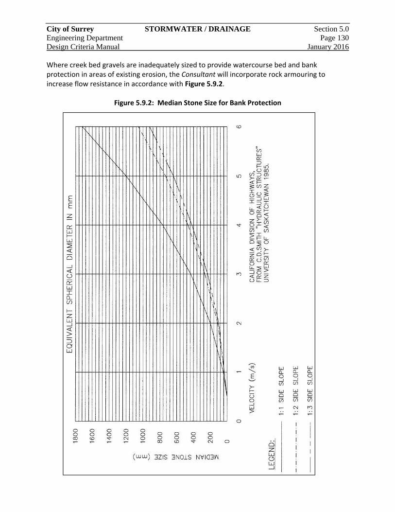
City of Surrey STORMWATER / DRAINAGE Section 5.0 Engineering Department Page 130 Design Criteria Manual January 2016
Where creek bed gravels are inadequately sized to provide watercourse bed and bank protection in areas of existing erosion, the Consultant will incorporate rock armouring to increase flow resistance in accordance with Figure 5.9.2.
Figure 5.9.2: Median Stone Size for Bank Protection
City of Surrey STORMWATER / DRAINAGE Section 5.0 Engineering Department Page 131 Design Criteria Manual January 2016
5.9.5.3 Hydraulic Structures
Hydraulic structures are used in storm runoff drainage works to control water. Hydraulic structures include, but are not necessarily limited to, energy dissipaters, channel drops or check dams, bridges, culverts, acceleration chutes, and baffle chutes. A brief description of these structures is included below. Detailed hydraulic design procedures, and sometimes physical modelling are required to design of hydraulic structures.
5.9.5.4 Energy Dissipaters
Energy dissipaters are often necessary at the end of outfall sewers or channels to velocities prior to entering a receiving water body. Stilling basins, a type of energy dissipater, are useful at locations where the Consultant wants to convert super‐critical flow to subcritical flow to permit placid water in a pool area downstream of a high velocity channel. Baffle chutes are energy dissipaters useful where side channel ponding areas exist for temporary detention of storm runoff water. 5.9.5.5 Drops or Check Dams
The use of drops or check dams is a convenient and economical way to reduce the effective slope of a natural or artificial channel. In general, the vertical height of the drop should be kept minimal so as to reduce erosion and turbulence problems. With natural channels, the use of check dams is often preferable. Both drops and check dams must accommodate fish passage requirements and possibly fish ladders, as directed by the Engineer.
5.9.5.6 Bridges and Culverts
The use of a bridge provides for a roadway crossing of the channel, whereas a culvert permits a channel to cross under a roadway. Bridges should not unduly restrict or adversely affect the flow character of the channel. Adequate hydraulic opening area should be allowed. Culverts on the other hand may restrict the flow character of the channel.
5.9.5.7 Acceleration Chutes
Acceleration chutes can be used to maximize the use of limited downstream right‐of‐way, and to reduce downstream channel and sewer costs. Chutes should only be used where environmental design concepts permit the use of high velocity flow. Generally, in urban drainage design, open channels should have low velocity flow.
SECTION 6
Transportation System
City of Surrey TRANSPORTATION Section 6.0 Engineering Department SYSTEM Page 132 Design Criteria Manual January 2016
6 TRANSPORTATION SYSTEM
6.1 General
This Section provides criteria and guidelines for the planning and designing of transportation infrastructure, including but not limited to roads, intersections, access, pedestrian/cyclist facilities, pavement structure, street lighting, and traffic control.
6.1.1 Applicable External Documents and Guidelines
The following will be read and used in conjunction with this Section:
a. Transportation Association of Canada (TAC) “Geometric Design Guide for Canadian Roads”
b. Ministry of Transportation & Infrastructure “BC Supplement to TAC Geometric Design Guide”
c. Manual of Uniform Traffic Control Devices of Canada (Published by TAC)
6.1.2 Road Classification & Network
All Highways are classified into the following categories:
a. Major Road Network (MRN) are specified in the Road Classification Map.
b. Arterial and Collector Roads are specified in the Road Classification Map.
c. Local Road standards shall be defined by the Engineer and for the purposes of utility servicing all Local Roads longer than 200m and/or servicing more than 100 dwelling units shall be classified as through Locals.
6.1.3 Road Allowance Widths
Required road dedication for Arterial and Collector Roads are identified in in Table 2.2.3. Required road dedication for Local Roads are identified in Table 2.2.2. City required dedication widths do not necessarily accommodate the requirements of external utilities. For subdivision servicing designs in these cases, arrangements must be made with those utilities to accommodate servicing of the site.
City of Surrey TRANSPORTATION Section 6.0 Engineering Department SYSTEM Page 133 Design Criteria Manual January 2016
6.1.4 Transportation Impact Analysis
Transportation Impact Analysis (TIA) may be required for new developments which are expected to generate approximately 150 trips during the peak hour of the generator. The primary purpose of a TIA is to:
a. Assess the impact of the proposed development traffic on pedestrian, cyclist, transit, and automotive infrastructure; and
b. Recommend Transportation Demand Management strategies as well as on and off site infrastructure improvements required to mitigate these impacts on existing and planned City infrastructure.
The typical threshold size of developments required to initiate a transportation impact analysis are generally as follows:
Single Family Zones ‐ 150 units Multi‐Family Zones ‐ 250 units Commercial Zones ‐ 25,000 sq. ft. GLA (2,323 sq. m) Office Zones ‐ 100,000 sq. ft. GFA (9,290 sq. m) Industrial Zones ‐ 150,000 sq. ft. GFA (13,935 sq. m) Institutional Zones ‐ 400 students/members
Note: GFA refers to Gross Floor Area GLA refers to Gross Leasable Area
The requirements for a TIA are at the discretion of the Engineer and may be required below the threshold amounts to respond to issues such as, but not limited to, the impact the development will have on an already congested road network, high collision locations or where site access or other safety issues are of concern. The requirements of the TIA are outlined in the City’s Terms of Reference for Transportation Impact Analysis.
6.1.5 Lot Grading for Road Frontages
All developments must grade the full site frontage along the ultimate property line to an elevation that shall be within 300mm of the ultimate road centerline elevation. All lot grading plans fronting Arterial Roads must be submitted to the Engineer for review.
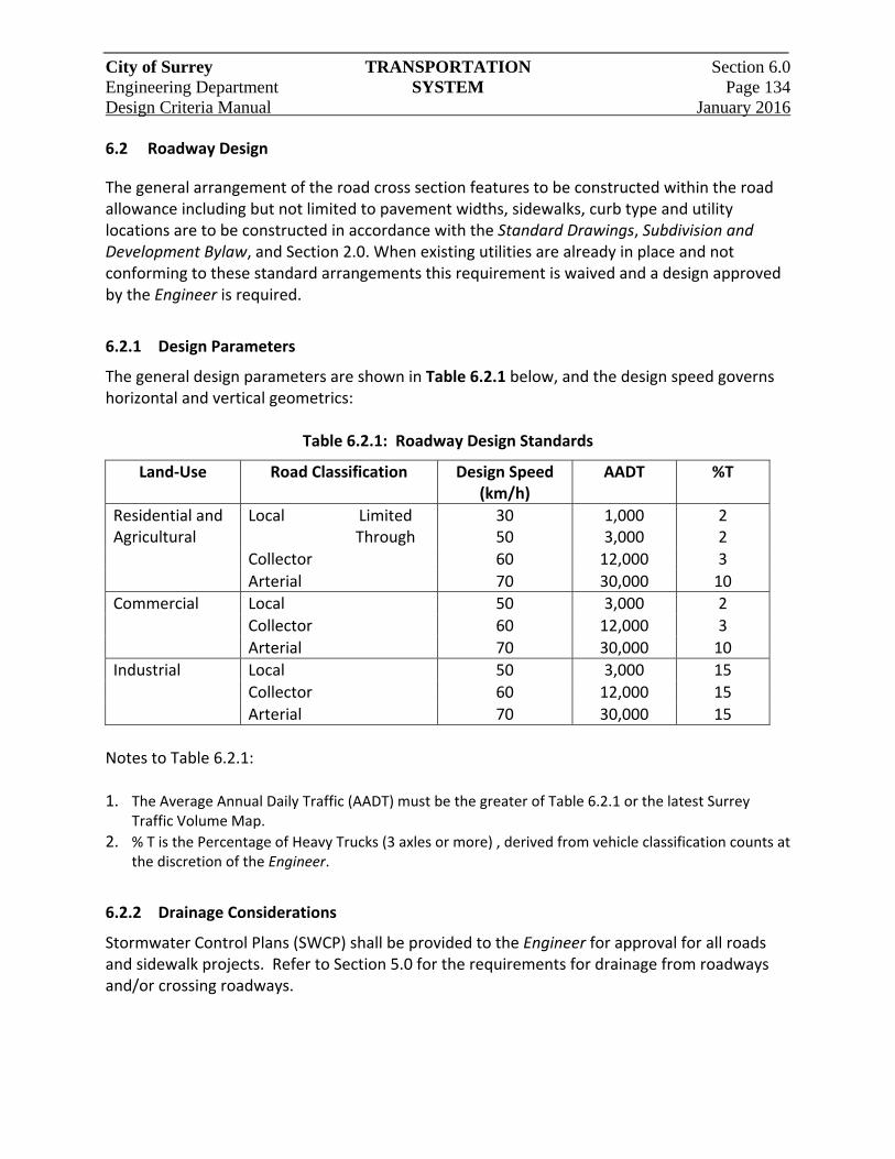
City of Surrey TRANSPORTATION Section 6.0 Engineering Department SYSTEM Page 134 Design Criteria Manual January 2016
6.2 Roadway Design
The general arrangement of the road cross section features to be constructed within the road allowance including but not limited to pavement widths, sidewalks, curb type and utility locations are to be constructed in accordance with the Standard Drawings, Subdivision and Development Bylaw, and Section 2.0. When existing utilities are already in place and not conforming to these standard arrangements this requirement is waived and a design approved by the Engineer is required.
6.2.1 Design Parameters
The general design parameters are shown in Table 6.2.1 below, and the design speed governs horizontal and vertical geometrics:
Table 6.2.1: Roadway Design Standards
Land‐Use Road Classification Design Speed (km/h)
AADT %T
Residential and Agricultural
Local
Limited Through
30 50
1,000 3,000
2 2
Collector 60 12,000 3
Arterial 70 30,000 10
Commercial Local 50 3,000 2
Collector 60 12,000 3
Arterial 70 30,000 10
Industrial Local 50 3,000 15
Collector 60 12,000 15
Arterial 70 30,000 15
Notes to Table 6.2.1: 1. The Average Annual Daily Traffic (AADT) must be the greater of Table 6.2.1 or the latest Surrey
Traffic Volume Map.
2. % T is the Percentage of Heavy Trucks (3 axles or more) , derived from vehicle classification counts at the discretion of the Engineer.
6.2.2 Drainage Considerations
Stormwater Control Plans (SWCP) shall be provided to the Engineer for approval for all roads and sidewalk projects. Refer to Section 5.0 for the requirements for drainage from roadways and/or crossing roadways.
City of Surrey TRANSPORTATION Section 6.0 Engineering Department SYSTEM Page 135 Design Criteria Manual January 2016
6.2.3 On‐Street Parking
On‐street parking, typically as parallel parking, is provided on City roads within the general arrangement of the road cross‐sections in accordance with the Standard Drawings. When alternative on‐street parking is provided, such as angled or back‐in angled parking, a non‐standard design will be required that will require additional pavement width and road dedication. Parking management controls will be applied at the discretion of the Engineer as required to ensure the safe and free movement of traffic in accordance with applicable by‐laws. These may include but are not limited to, no parking or no stopping to maintain sight lines at intersections and driveways and controls on the time of day and length of stay. Parking Lanes, or pockets, may be delineated through the use of curb extensions at road intersections. Curb extensions may also be used at Lanes, multi‐family residential and commercial access to Local and Collector Roads.
6.2.4 Maximum Road Lengths
Maximum road lengths are applicable for ultimate limited Local Roads(i.e. cul‐de‐sacs, P‐loops, dead ends) and interim roads of all classifications that have only a single point of access to an intersecting Highway that has more than one point of access with another Highway. Maximum road lengths are required to limit the number of dwelling units and overall vehicle trips serviced by a single point of access. Lack of accessibility and connectivity increases the potential for temporary blockages that can impede emergency access and place additional strain on the transportation network. Maximum road lengths are based on land‐use are identified in Table 6.2.2.
Table 6.2.2: Maximum Road Length Standards
Zones Max. Length (m)
Commercial, industrial, multi‐family, small lot single family residential (i.e. RF‐12 or smaller)
120
All other single family residential zones
220
Agricultural Zones 400
City of Surrey TRANSPORTATION Section 6.0 Engineering Department SYSTEM Page 136 Design Criteria Manual January 2016
The above maximum lengths may be relaxed at the discretion of the Engineer, and in these special circumstances may require:
a. Fire sprinklers of standard acceptable to the City with restrictive covenant for their ongoing necessity for those properties fronting the overall length of the road; and
b. An alternate emergency access route.
6.2.4.1 Measurement
The length of the road shall be measured along the road’s centerline from the ultimate road allowance of the intersecting Highway to either the center of a cul‐de‐sac bulb, or to the finished pavement edge. 6.2.4.2 P‐Loops
P‐loops shall have a maximum total length of 500m including entrance leg. The entrance leg shall not exceed 220m in length.
6.2.4.3 Temporary Turnarounds
Temporary turnarounds shall be designed for interim roads of all classifications longer than 100m, and less than the maximum lengths in Table 6.2.2 that are to be extended in the future unless otherwise required by the Engineer. Temporary turnarounds shall be constructed as a paved cul‐de‐sac bulb with all necessary rights‐of‐way and cash‐in‐lieu for removal. Alternatively a hammer head (3‐point) turnaround is also acceptable. 6.2.4.4 Temporary Alternate Access
Temporary alternate access is required for interim roads of all classifications that on an interim basis exceed the maximum length of Table 6.2.2 but will ultimately have more than one point of access. The temporary access shall have a minimum width of 6.0m and have structural capability to support 9.1 tonne axle loading.
6.2.5 Medians
The median is defined as the area between opposing Lanes of traffic and can either be pavement markings only or with a physical barrier. Raised medians are a physical barrier required on Arterial Roads to improve the safety and operations of the road and to provide access management. Raised medians shall typically be landscaped with low height planting in order to reduce headlight glare and discourage mid‐block pedestrian crossings at undesignated locations. All proposed landscaping planting designs must be approved by the Engineer. Minimum raised median width with landscaping is 2.9m. Raised medians below this width shall have stamped and colourized concrete treatment between the curbface. All raised medians

City of Surrey TRANSPORTATION Section 6.0 Engineering Department SYSTEM Page 137 Design Criteria Manual January 2016
shall use barrier curb and gutter for design speeds less than or equal to 70 km/hr and use median curb for design speeds in excess of 70 km/hr. Painted medians, as two‐way left turn lanes, are permitted as a substitute to raised medians on Arterial Roads within the Agricultural Land Reserve to accommodate farm vehicle movements and access. All other painted medians are approved as directed by the Engineer.
6.2.6 Boulevards
The area between the vehicle travel edge (pavement edge or curb) and the property line is defined as the boulevard and typically contains the sidewalk. The sidewalk should be located adjacent to the property line in the boulevard unless environmental or topographical reasons prevent it.
Standard landscaping in boulevards shall be limited to absorbent topsoil and sod with street trees unless approved by the Engineer. If planting pockets of shrubbery, trees and ground cover are used adjacent to the curb the plants selected for these areas shall be a species that will not grow to restrict pedestrian, cyclist, and vehicle sight lines at driveways and intersections, encroach into traffic Lanes or sidewalks, obscure street signs and signals or have roots that damage pavement. Where there are environmental, topographical, or property constraints the minimum landscaping width between curb face and sidewalk is 1.5m. Below this width a concrete hard surface utility strip with minimum width of 1.1m shall be used in accordance with the Standard Drawings. Existing unimproved boulevards on Arterial Roads that are modified for underground servicing and/or lot grading requirements shall be reinstated with either of the following treatments as directed by the Engineer.
a. Native soil backfill with topsoil and sod and extruded curb; and
b. Where approved for interim parking a maximum 2.5m wide gravel shoulder with native soil backfill and topsoil and sod up to sidewalk and or property line.
City of Surrey TRANSPORTATION Section 6.0 Engineering Department SYSTEM Page 138 Design Criteria Manual January 2016
6.3 Geometric Road Design
6.3.1 Horizontal Design
Horizontal design shall reflect the parameters identified in this section and otherwise be in accordance with TAC Geometric Design Guide for Canadian Roads. Horizontal alignment shifts to avoid features to be preserved or for other design reasons must be treated carefully. Deflection angles can result in abrupt “kinks” in driving alignment unless the shift is effectively limited to 1 to 100 range. Long curves to approximate the 1 to 100 shift must be used to avoid “apparent” kinks visible only to a driver’s line of sight. 6.3.1.1 Simple Curves
Simple curves may be used for road design on Local and on Collector Roads where the tangent angle is less than 30 degrees. All curves should have a minimum 20m tangent between any road intersection and the curve and ‘S’ curves must have 20m tangent separating the two curves.
The minimum allowable radius for a simple curve with normal crown, and with super elevation or in the form of a reverse crown is shown in Table 6.3.1.
Table 6.3.1: Allowable Radius for a Simple Curve
Typical Road Classification
Design Speed (kph)
Friction Factor “f”
Radius e = ‐0.025 Normal Crown
Radius e = +0.025 Reverse Crown
Limited Local 30 0.31 25m ‐
Through Local 40 0.25 60m ‐
Collector 50 0.21 110m ‐
Arterial 60 0.18 185m 140m
Arterial 70 0.15 310m 190m
6.3.1.2 Right‐Angle Curves
Right angle curves shall be permitted for local residential roadways at the discretion of the Engineer where there are topographical or site constraints provided the inside curb return radius is not less than 9.0m.
6.3.2 Vertical Design
The road profile, curb and sidewalk grades must suit the ultimate profile and cross‐section of the road and not the existing condition. Design drawings should clearly indicate the ultimate road profile beyond the development site frontage. The Engineer may allow interim works in which case the interim and ultimate design will be required. Special consideration must be given to provide adequate site distance and transition distance when combining horizontal and vertical curves.
City of Surrey TRANSPORTATION Section 6.0 Engineering Department SYSTEM Page 139 Design Criteria Manual January 2016
6.3.2.1 Vertical Curves
Vertical curves are to be designed as per TAC Geometric Design Guide for Canadian Roads and may be omitted where the algebraic difference in grades does not exceed 2% for Local Road sand 1% for other streets. 6.3.2.2 Longitudinal Road Grades
Minimum longitudinal grade shall be 0.5% to accommodate drainage. The maximum longitudinal grades shall be:
a. Local Residential Roads 12%
b. Cul‐de‐sac uphill 8%
c. Cul‐de‐sac downhill (where permitted by the Engineer) 5%
d. Collector Roads, Local Industrial/ Commercial Roads 8%
e. Arterial Roads 7%
6.3.3 Cross fall
Standard pavement cross fall shall be 2.5% with the crown point to the center of the travelled pavement. Variations to the cross‐slope (including altering cross‐slope or employing a one‐way crossfall) may be permitted, at the discretion of the Engineer, where extreme topography applies. Variations and transitions in the crown should be accommodated in the median and/or left turn bay with the travelled portion of the crown maintaining a constant cross fall where possible.
6.4 Intersection Design
6.4.1 Alignment
Intersections shall be designed at right angles, or as close as possible. Additionally, a minimum 20m tangent should be provided at all intersection approaches. Intersections proposed on curves or near the crest of hills are to be avoided. These proposed intersections are subject to sight line analysis in accordance with TAC. Where practical, profiles on the approach to an intersection should be flattened for a minimum distance of 20m back from the cross street to facilitate a smooth crossing. Where signalization is planned or anticipated in the future, cross slopes on through streets shall be reduced to between 0.5‐1.5% within the intersection.
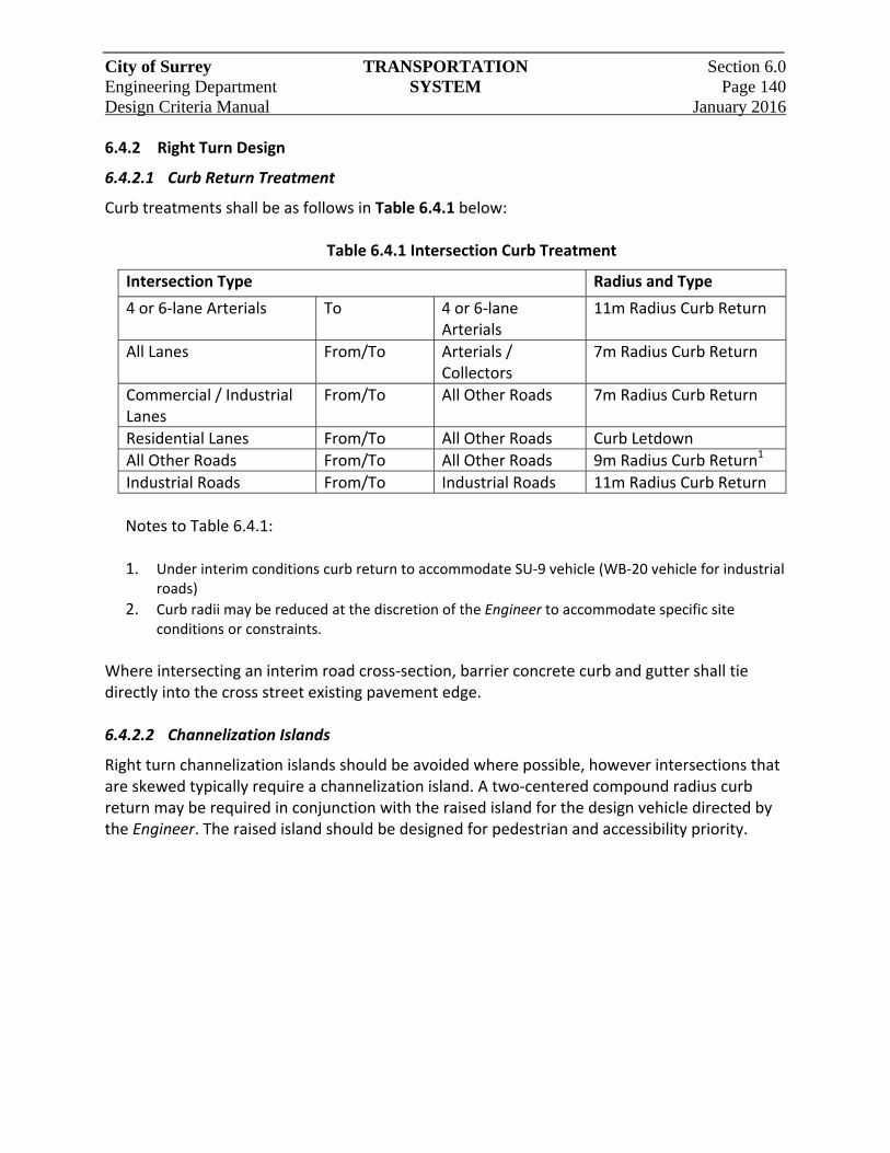
City of Surrey TRANSPORTATION Section 6.0 Engineering Department SYSTEM Page 140 Design Criteria Manual January 2016
6.4.2 Right Turn Design
6.4.2.1 Curb Return Treatment
Curb treatments shall be as follows in Table 6.4.1 below:
Table 6.4.1 Intersection Curb Treatment
Intersection Type Radius and Type
4 or 6‐lane Arterials To 4 or 6‐lane Arterials
11m Radius Curb Return
All Lanes From/To Arterials / Collectors
7m Radius Curb Return
Commercial / Industrial Lanes
From/To All Other Roads 7m Radius Curb Return
Residential Lanes From/To All Other Roads Curb Letdown
All Other Roads From/To All Other Roads 9m Radius Curb Return1
Industrial Roads From/To Industrial Roads 11m Radius Curb Return
Notes to Table 6.4.1: 1. Under interim conditions curb return to accommodate SU‐9 vehicle (WB‐20 vehicle for industrial
roads)
2. Curb radii may be reduced at the discretion of the Engineer to accommodate specific site conditions or constraints.
Where intersecting an interim road cross‐section, barrier concrete curb and gutter shall tie directly into the cross street existing pavement edge. 6.4.2.2 Channelization Islands
Right turn channelization islands should be avoided where possible, however intersections that are skewed typically require a channelization island. A two‐centered compound radius curb return may be required in conjunction with the raised island for the design vehicle directed by the Engineer. The raised island should be designed for pedestrian and accessibility priority.
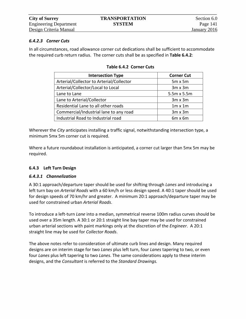
City of Surrey TRANSPORTATION Section 6.0 Engineering Department SYSTEM Page 141 Design Criteria Manual January 2016
6.4.2.3 Corner Cuts
In all circumstances, road allowance corner cut dedications shall be sufficient to accommodate the required curb return radius. The corner cuts shall be as specified in Table 6.4.2:
Table 6.4.2 Corner Cuts
Intersection Type Corner Cut
Arterial/Collector to Arterial/Collector 5m x 5m
Arterial/Collector/Local to Local 3m x 3m
Lane to Lane 5.5m x 5.5m
Lane to Arterial/Collector 3m x 3m
Residential Lane to all other roads 1m x 1m
Commercial/Industrial lane to any road 3m x 3m
Industrial Road to Industrial road 6m x 6m
Wherever the City anticipates installing a traffic signal, notwithstanding intersection type, a minimum 5mx 5m corner cut is required. Where a future roundabout installation is anticipated, a corner cut larger than 5mx 5m may be required.
6.4.3 Left Turn Design
6.4.3.1 Channelization
A 30:1 approach/departure taper should be used for shifting through Lanes and introducing a left turn bay on Arterial Roads with a 60 km/h or less design speed. A 40:1 taper should be used for design speeds of 70 km/hr and greater. A minimum 20:1 approach/departure taper may be used for constrained urban Arterial Roads. To introduce a left‐turn Lane into a median, symmetrical reverse 100m radius curves should be used over a 35m length. A 30:1 or 20:1 straight line bay taper may be used for constrained urban arterial sections with paint markings only at the discretion of the Engineer. A 20:1 straight line may be used for Collector Roads. The above notes refer to consideration of ultimate curb lines and design. Many required designs are on interim stage for two Lanes plus left turn, four Lanes tapering to two, or even four Lanes plus left tapering to two Lanes. The same considerations apply to these interim designs, and the Consultant is referred to the Standard Drawings.
City of Surrey TRANSPORTATION Section 6.0 Engineering Department SYSTEM Page 142 Design Criteria Manual January 2016
6.4.3.2 Storage Length
Typical minimum storage bay lengths on Arterial Roads are 50m and are increased to 75m in industrial zones (to accommodate three WB‐20 Design Vehicles. For all other roads 40m is standard left turn bay length and 30m is the minimum. The storage length (exclusive of taper) for unsignalized left turn bays can be calculated using TAC Equation 2.3.3. For signalized intersections storage length should be calculated by the formula:
S = 2 x (cph) x VL
Where: cph = cycles per hour VL = design vehicle length (use 7.0m) S = storage length (
6.4.4 Roundabouts
Single and multiple Lane roundabouts are a form of intersection control and the design shall include analysis to ensure suitable capacity, level‐of‐service, queue lengths, vehicle deflection, width of entry/exit flares and design speeds.
6.4.4.1 Design Parameters
Unless otherwise stated by the Engineer the design vehicles shall be:
a. Single Lane roundabout: an intercity bus (TAC I‐BUS) should be entirely accommodated with full movements within the travel way. Larger vehicles are expected to utilize the truck apron which should typically accommodate a WB‐20 vehicle on Arterial Roads and WB‐12 on Collector Roads typical minimum inscribed diameter width is 30.0m;
b. Multi‐Lane roundabouts shall be based on the largest frequent vehicle (typically WB‐20) side by side with a passenger vehicle.
Cyclist ramps and bypass path to pedestrian crossings shall be provided on all bicycle routes and where sidewalk widths support shared use with pedestrians. Entry width shall be a minimum of 4.2m non‐curb and 5.1m for curb section (curb face to curb face). Circulating width is primarily based on design vehicles and the number of entry Lanes. This should be at least as wide as maximum entry width and will normally not exceed 1.2 times maximum entry width.
City of Surrey TRANSPORTATION Section 6.0 Engineering Department SYSTEM Page 143 Design Criteria Manual January 2016
6.4.4.2 Center Islands
The outer perimeter of the island shall be planted with low‐lying shrubs, grass, or groundcover so that stopping sight distance requirements are maintained for vehicles within the circulatory roadway. Shrubs may be appropriate within the inner portion of the center island to improve long range conspicuity of the roundabout while maintaining a 4.5m clearance from the outer circumference of the truck apron. A power conduit shall be installed to the roundabout terminating at a junction box. The conduit should be positioned to provide convenient connection to an existing power source and shall be constructed to current street lighting specifications.
6.4.4.3 Splitter Islands
Splitter islands shall be filled, stamped and colourized to be consistent with the truck apron. In exceptional cases where turning movements cannot be accommodated for the design vehicle (e.g. in cases of retro‐fitting), splitter islands shall be constructed with mountable curbing and suitable load bearing foundations to facilitate wider turning movements. This shall be undertaken at the Engineer’s direction.
6.4.5 Traffic Circles
Traffic Circles are a form of intersection control and a traffic calming device that is applicable to Local Roads only. It has a smaller raised island located in the center of the intersection that requires vehicles to yield on entry into the circle. 6.4.5.1 Design Parameters
The design vehicle shall be SU‐9, unless specified otherwise by the Engineer. The minimum entry width shall be a minimum of 4.2m. Circulating width should be at least as wide as maximum entry width and will normally not exceed 1.2 times maximum entry width. 6.4.5.2 Center Islands
The traffic circles raised center island diameter shall be no less than 2.0m. Where the diameter exceeds 4.0m, a power conduit shall be installed to the circle, terminating at a junction box. The conduit should be positioned to provide convenient connect to an existing power source and shall be constructed to current street lighting specifications. 6.4.5.3 Splitter Islands & Pedestrian Crossing
Splitter islands shall be painted insuring an adequate deflection into the traffic circle, with a deflection path tangential to the truck apron. Pedestrian crosswalk letdowns shall be positioned to best accommodate alignment to the facing letdown on the opposite side of the crossing. The crossing shall be a minimum of 1.0m back from the yield line to accommodate a potential 3m wide crosswalk.
City of Surrey TRANSPORTATION Section 6.0 Engineering Department SYSTEM Page 144 Design Criteria Manual January 2016
6.4.6 Traffic Buttons
Traffic Buttons are a form of intersection control and traffic calming device and applicable to Local Roads only. It shall only be considered at the approval of the Engineer where there are topographical, environmental or property constraints to installing a traffic circle. The traffic button has a raised dome of asphalt in the center of the intersection that requires vehicles to yield on entry into the circle but is mountable by larger vehicles to accommodate the wider radius turning movements. 6.4.6.1 Design Parameters
The center island will be domed stamped asphalt, painted white. The island profile shall have a side profile ranging between 10‐ 15% with a vertical height not exceeding 125mm. For larger buttons the top shall be flattened to remain within vertical constraints. The complete structure shall be designed to be H20 load bearing. The traffic button shall be constructed with reverse roll‐over curb along its outer boundary. Entry width into the travel way shall be a minimum of 4.2m. Circulating width is primarily based on passenger cars. This should be at least as wide as maximum entry width and will normally not exceed 1.2 times the maximum entry width. The design should accommodate painted splitter islands to ensure an adequate deflection into the circulatory Lane with a swept path tangential to the center island reverse roll‐over curb. Where road width is limited, a painted splitter island can be replaced at the discretion of the Engineer with a solid yellow centerline of a minimum 15m length. A 3m break will be inserted into this line to indicate a pedestrian crossing, with a 1m setback from the yield line position.
6.4.7 Sight Distance
Turning Sight Distance (TSD) is desirable to provide a vehicle sufficient time to cross, enter or exit the minor to/from the major road before the arrival of an approaching vehicle, and shall be calculated by the formula given in the TAC Geometric Design Guide. If TSD cannot be provided then at a minimum, there must be sufficient stopping sight distance (SSD) for a driver on the major to perceive potential conflicts and to carry out the actions needed to negotiate the potential conflict safely.
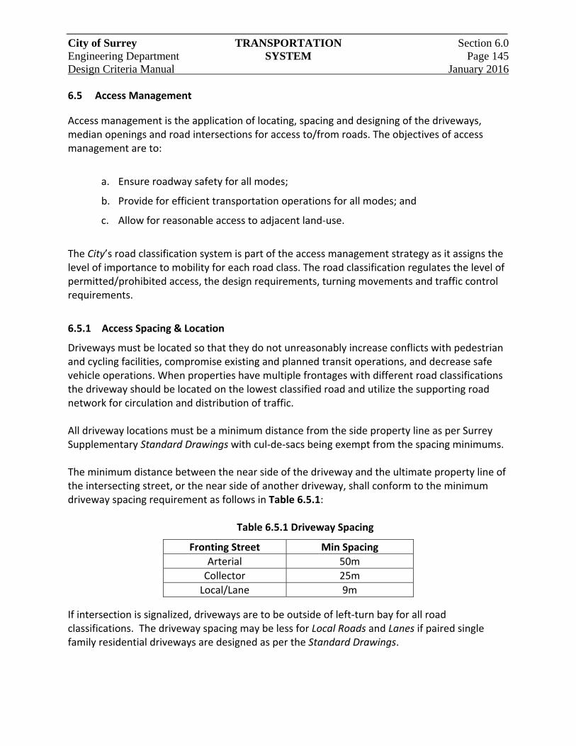
City of Surrey TRANSPORTATION Section 6.0 Engineering Department SYSTEM Page 145 Design Criteria Manual January 2016
6.5 Access Management
Access management is the application of locating, spacing and designing of the driveways, median openings and road intersections for access to/from roads. The objectives of access management are to:
a. Ensure roadway safety for all modes;
b. Provide for efficient transportation operations for all modes; and
c. Allow for reasonable access to adjacent land‐use.
The City’s road classification system is part of the access management strategy as it assigns the level of importance to mobility for each road class. The road classification regulates the level of permitted/prohibited access, the design requirements, turning movements and traffic control requirements.
6.5.1 Access Spacing & Location
Driveways must be located so that they do not unreasonably increase conflicts with pedestrian and cycling facilities, compromise existing and planned transit operations, and decrease safe vehicle operations. When properties have multiple frontages with different road classifications the driveway should be located on the lowest classified road and utilize the supporting road network for circulation and distribution of traffic. All driveway locations must be a minimum distance from the side property line as per Surrey Supplementary Standard Drawings with cul‐de‐sacs being exempt from the spacing minimums. The minimum distance between the near side of the driveway and the ultimate property line of the intersecting street, or the near side of another driveway, shall conform to the minimum driveway spacing requirement as follows in Table 6.5.1:
Table 6.5.1 Driveway Spacing
Fronting Street Min Spacing
Arterial 50m
Collector 25m
Local/Lane 9m
If intersection is signalized, driveways are to be outside of left‐turn bay for all road classifications. The driveway spacing may be less for Local Roads and Lanes if paired single family residential driveways are designed as per the Standard Drawings.
City of Surrey TRANSPORTATION Section 6.0 Engineering Department SYSTEM Page 146 Design Criteria Manual January 2016
Driveways should be located outside of any existing and planned turning Lanes of signalized and unsignalized intersections to a minimum of 120m. If more than 120m of frontage is not available, or the Engineer allows a driveway within the intersection area, then the driveways are to be located as far away from the intersecting roads as possible and are subject to median restriction right‐in/right‐out access only. Alignment and/or spacing from existing driveways on the opposite side of a roadway is required to avoid conflicting turning movements unless an existing raised median divides the roadway.
6.5.2 Arterial Road Regulations
Arterial Roads are intended to carry high volumes of traffic at higher operating speeds. They are also important corridors for pedestrians, cyclists and transit. Driveways reduce the carrying capacity and reduce operational performance by increasing the potential conflict points on them. Thus the City seeks to regulate the number of accesses and restrict permitted turning movements onto them according to land‐use. 6.5.2.1 Residential
Single Family and Multi‐Family residential driveways, onto Arterial Roads, shall not be permitted when other means of access is available. When permitted, or no alternative is available, residential driveways on Arterial Roads shall be restricted to right‐in/right‐out turning movements only. A restrictive Covenant shall be provided by the Developer. Direct access to multi‐family underground parking ramps is not permitted due to sight line limitations and safety. Left‐in access from an Arterial Road may be considered for a multi‐family site of 200 or more units. 6.5.2.2 Agricultural, Commercial, Industrial, & Institutional
Limited direct access to Arterial Roads for agricultural, commercial, industrial, and institutional may be permitted subject to the requirements of Section 6.5.1. If land‐use is compatible, joint access with adjacent sites may be required. Left‐in access from an Arterial Road may be considered for.
a. Commercial site of 150,000 sq.ft. GFA or more;
b. Industrial site of 10 ha or more;
c. Shared driveway of three (3) or more properties; and
d. Instances when the operation of the surrounding road network is benefited.
City of Surrey TRANSPORTATION Section 6.0 Engineering Department SYSTEM Page 147 Design Criteria Manual January 2016
In Zones CG‐1 and CG‐2, only one driveway shall be permitted to each Arterial Road to which the site fronts. These driveways shall be located as far removed from an intersection as possible. A second driveway may be permitted when one of the following conditions exist:
a. Where the subject site fronts entirely to one Arterial Road; and
b. Where, at the discretion of the Engineer, a second driveway may be required for on‐site circulation of the design vehicle.
6.5.3 Collector Road Regulations
Collector Roads are primarily for collecting and distributing traffic between Local Roads but are permitted direct access to a property. Access to a Collector Road for single family residential properties are only permitted if the lot does not have access to a Local Road or Lane. All other residential properties shall be permitted only one (1) driveway. All residential lots having less than 18.0m frontage shall have paired driveways to accommodate on‐street parking. Limited direct access to Collector Roads for agricultural, commercial, industrial, and institutional may be permitted subject, but not limited to, the location requirements of Section 6.5.1. If land‐use is compatible, joint access with adjacent sites may be required. A second driveway may be permitted when one of the following conditions exist:
a. Where the subject site fronts entirely to one Collector Road.
b. Where, at the discretion of the Engineer, a second driveway may be required for on‐site circulation of the design vehicle.
c. When the number of multi‐family residential units is in excess of 100.
6.5.4 Local Roads and Lanes Regulations
Local Roads primarily provide internal circulation within the neighbourhood and direct access to a property. Direct access to Local Roads and Lanes are permitted subject for all uses to the access requirements of Section 6.5.1. All single family residential lots shall be permitted only one (1) driveway, and a separate parking pad for secondary suites independent of the primary dwelling driveway is not permitted. All single family residential lots having less than 18.0m frontage shall have paired driveways to maximize on‐street parking.
City of Surrey TRANSPORTATION Section 6.0 Engineering Department SYSTEM Page 148 Design Criteria Manual January 2016
A second driveway may be permitted when of the following conditions exist:
a. Where the subject site fronts entirely to one Local Road;
b. Where, at the discretion of the Engineer, a second driveway may be required for on‐site circulation of the design vehicle;
c. Multi‐family residential developments in excess of 100 units; or
d. RH‐G or lower density lots (Suburban Designation) with frontage greater than 26 m may be permitted U‐shaped driveways with ingress/egress of 6 m width and minimum 11 m between driveways.
6.5.5 Driveway Design
6.5.5.1 Grades/Elevation
Driveway grade changes must be designed so vehicles will not “hang up” or “bottom out”. To accommodate this, a landing area shall be provided for a minimum of 6m into a site from the ultimate property line at +/‐ 5% maximum. The remainder of the driveway grade is based on road classification as follows:
a. Local 15% maximum
b. Collector 10% maximum
c. Arterial 10% maximum
Driveways designed in advance of ultimate road widening shall not vary in elevation at property line by more than 300mm from the elevation of the centerline of the road, and shall suite the ultimate elevation for the sidewalk. 6.5.5.2 Entrance Design
All driveway widths shall be as per the Standard Drawings and reflect the standard width as priority over the minimum width. All driveways shall be at right angles to the roadway pavement edge. Driveways permitted on Arterial and Collector Roads with right‐in or right‐out only restrictions may have driveways at 45 or 60 degrees to the roadway with a mountable delta island for SU‐9 and fire truck access. All driveways shall be concrete letdown style rather than curb return to accommodate pedestrian priority at the crossing, except for:
a. Major driveway crossings with more than 100 vehicles per hour;
b. Major driveway crossings on an Arterial Road with left‐turn access; and
c. Fire halls.
City of Surrey TRANSPORTATION Section 6.0 Engineering Department SYSTEM Page 149 Design Criteria Manual January 2016
Developments generating more than 200 trips in any hour may be required to provide a minimum 2m and a maximum 4mwide median in the drive aisle to separate opposing traffic. The median nose should be set back a minimum 0.6m from the property line and be level or with low landscaping below driver eye height. 6.5.5.3 Queuing Storage
Queuing storage, as measured from the ultimate property line, is the projection of the driveway into the site with no parking stalls or cross aisles directly accessible to it. This storage must be clear of all obstructions including speed humps, gates, and fences.
Queuing storage shall conform to the minimum lengths in Table 6.5.2, and additional queuing length may be required by the Engineer and/or as determined by a traffic impact study:
Table 6.5.2 Parking Queuing
Parking Stalls Length (m)
0‐100 6
101‐150 12
151‐200 18
>200 24
Typical truck access to industrial sites with truck traffic shall have minimum queuing storage of 24m, or the minimum length of the design vehicle for the site. 6.5.5.4 Construction Standards
Driveway crossings, including thickness of pavement, concrete and structure shall conform to the Standard Drawings. All existing and proposed driveways shall be located on the design drawings. All existing driveways not being used by a proposed development or to a vacant lot shall be removed and the boulevard reinstated with the appropriate treatment. The driveway between curb and sidewalk must be constructed in conjunction with the servicing works for all residential zones. Water, sanitary sewer and storm sewer services laterals should avoid being located under the driveway unless required by environmental, topographical, or other reasons. Driveways must maintain a minimum 1.0m horizontal clearance from all above ground utilities. If the height of the utility is greater than 0.6m, the sight triangle as determined by stopping sight distance (TAC Geometric Design Guide) must be achieved.
City of Surrey TRANSPORTATION Section 6.0 Engineering Department SYSTEM Page 150 Design Criteria Manual January 2016
6.5.6 Frontage Roads
Frontage roads can be used to provide access to residences fronting Arterial Roads, where they have either been identified for the area. At the conceptual stage, the ultimate frontage road layout must be established, as per the Standard Drawings, including the number and location of access points to the frontage road. It is preferred that all frontage road accesses link to internal roads within the development, however, access to Collector Roads external to the development may be permitted at the discretion of the Engineer. 6.5.6.1 Staging
When the proposed frontage road does not have direct access to a Local or Collector Road, access can be temporarily permitted along an Arterial Roadway. Once the frontage road is developed to its ultimate configuration, all temporary access to the Arterial Road will be removed and access will be from Collectors or other Local Roads. The Developer who installs a temporary arterial access will be required to deposit sufficient funds with the City to cover future removal costs of the access. 6.5.6.2 Design Elements
A 6.0m pavement width shall be provided on a frontage road, except where the frontage road is providing access to more than 50 lots or units, or is servicing commercial/industrial properties in which case the pavement width shall increase to 8.5m.
Double luminaires shall be provided to illuminate both the frontage road and the Arterial. Lamp wattage and pole spacing shall conform to Section 6.8. The frontage road/arterial boulevard shall be landscaped in accordance with the following guidelines to the satisfaction of the Engineer. Landscaping shall:
a. Provide an effective screen for headlights in opposite directions and promote traffic safety.
b. Be capable of low maintenance.
c. Be designed with consideration of preserving existing mature trees.
City of Surrey TRANSPORTATION Section 6.0 Engineering Department SYSTEM Page 151 Design Criteria Manual January 2016
6.5.7 Lanes
The primary purpose for Lanes is for access, so changes to the horizontal alignment should be avoided unless directed by the Engineer to ensure adequate sight lines for vehicle access/egress. When corners or T‐intersections are unavoidable, a supplementary 5.5m x 5.5m triangle road allowance shall be dedicated for visibility and the curb return. This triangle must be paved. To reduce speeds and discourage shortcutting, speed humps should be included with Lane construction for all Lanes with an ultimate length of 100m or more at 50m to 75m spacing. A Green Lane is an enhanced Lane with sidewalk on one side, pedestrian street lights and a landscaped boulevard. The Lanes primary purpose is still to provide access as well as an additional level of connectivity through multi‐family and commercial sites and between neighbourhoods where there may be site constraints in achieving the Local Road standard. Green Lanes are not a substitute for Local Roads and shall not be named.
6.6 Pedestrian System Design
6.6.1 Sidewalks
6.6.1.1 Sidewalk Provision
Sidewalks shall be provided on both sides of a road unless otherwise identified in Tables 2.2.2 to 2.2.4. Where sidewalks are provided on one side only as part of half road construction the sidewalk may be provided on the ultimate half section of road. In all single family residential zones, sidewalks are not required on limited Local Roads less than 50m in length unless they connect to a walkway or have in excess of 10 properties.
6.6.1.2 Design Parameters
Sidewalks shall be parallel to the curb and shall typically be located as far away from the edge of the vehicle travel surface as conditions will allow. Under circumstance where there are environmental, topographical, or property constraints, sidewalks may be located less than 2m from the curb, subject to Boulevard requirements in Section 6.2.6 and the approval of the Engineer. In Town Centres and locations where high pedestrian activity is expected the sidewalk may be permitted to cover the entire area between the curb and property line. In these cases boulevard tree grates shall be provided. Sidewalks shall remain continuous and level through driveway crossings. Where this is not possible, the entire sidewalk shall drop locally to the driveway elevation in order to preserve the 2% sidewalk crossfall.
City of Surrey TRANSPORTATION Section 6.0 Engineering Department SYSTEM Page 152 Design Criteria Manual January 2016
6.6.1.3 Alignment
Sidewalks should be linear and shall generally be contained with the road allowance. Where sidewalks form a part of a multi‐use pathway, they may be contained wholly or partially within a statutory right‐of‐way. Abrupt modifications to alignment shall use 3 m radius back‐to‐back curves to preserve existing above ground obstacles such as trees, hydrants, and poles. Sidewalks may meander only where there are environmental, topographical, or other constraints and must be approved by the Engineer. Sidewalks that form part of a multi‐use pathway may have a maximum meander from centerline equal to the path width.
6.6.1.4 Clearance
The clear width of the sidewalk shall be as shown in the Standard Drawings. In exceptional circumstances, a clear width of 1.2m may be considered in localized areas, subject to the approval of the Engineer. A minimum 0.3m offset to above ground obstructions is required and vertical clearance to trees and shrubs shall be a minimum of 2.5m. A 1.2m high handrail shall be provided for pedestrian safety where a drop with slope greater than 1:1.5 with a vertical drop greater than 0.6 m.
6.6.1.5 Crossfall
The sidewalk crossfall shall be 2%, sloping down from the property line to the curb to accommodate road allowance surface drainage. Under exceptional circumstances, this may be modified to accommodate other constraints, subject to the approval of the Engineer. Where the sidewalk grade slopes toward the property line, adequate drainage shall be provided. 6.6.1.6 Sidewalk Letdowns
Separated sidewalk letdowns shall be provided for crossing each leg of an intersection (two letdowns per corner), including all legs of a T‐intersection. Additionally, letdowns shall be provided for access to walkways and greenways. Letdowns shall be provided to facilitate crossing roads with medians at offset or staggered crossings or other when another facility is provided. At signalized intersections, the area within the road allowance corner cut shall be concrete. Sidewalk letdowns shall be exclusive of the sidewalk and the sidewalks shall remain level through a corner radius at minimum 1.5m in width. Where a sidewalk is built mid‐block and does not connect to an existing sidewalk, a temporary asphalt connection shall be built between the end of the sidewalk and the roadway.

City of Surrey TRANSPORTATION Section 6.0 Engineering Department SYSTEM Page 153 Design Criteria Manual January 2016
6.6.2 Engineering Walkways
Engineering walkways provide pedestrian network connection access between roads to supplement Local Road connectivity. Walkways shall be in dedicated road allowance only. Walkway lengths are measure between the projected ends of the intersecting opened road allowance. Walkway widths shall generally conform to the table listed in Table 6.6.1.
Table 6.6.1 Walkway Widths
Length Road Allowance Width Landscaping
0 – 40m 4m None
41 ‐ 80m 6m 2m Grass Optional
81 – 120m 8m 2 x 2m Grass
Over 120m 10m 2 x 3m Grass
The alignment should be linear in nature with a clear line of sight between both ends and avoid bends and kinks in the road allowance. The typical surface treatment width shall be 4m concrete surface for the entire width and designed for H20 loading and will be wide enough to accommodate the intended maintenance vehicles. Walkways adjacent to single family residential should use 1.8m high chain link fencing on each side for the length of the walkway. All other land‐uses may use alternatives in place of chain link fencing for aesthetic reasons. At the end of walkways locking post bollards shall be used to discourage unauthorized motor vehicle entry. Bollards shall be placed at 2m spacing and typically centered in the middle of the walkway travelled surface. Baffle gates are to be located for walkways with grades above 8% only.
6.6.3 Multi‐Use Pathways
Multi‐use pathways(MUP) are sidewalks and walkways that permit the use of cyclists and wheeled users. Where MUP’s replace the standard sidewalk (next‐to‐road paths) additional right‐of‐way is required. Where multi‐use pathways are off‐street the minimum right of way width is 10.0m wide. MUP’s shall be 4.0m wide as shown on the Standard Drawings. MUP surface treatment shall provide smooth surface treatment and typically be asphalt. MUP’s shall use locking posts bollards to restrict unauthorized vehicular access at all major road crossings, multi‐family residential, industrial, institutional and commercial driveway crossings. Bollards shall be placed at 2m spacing and typically centered in the middle of the MUP travelled surface.
City of Surrey TRANSPORTATION Section 6.0 Engineering Department SYSTEM Page 154 Design Criteria Manual January 2016
6.7 Pavement Design
6.7.1 General Instructions
The following criteria shall be followed for structural design of Highways: Asphalt Pavement Design ‐ accepted references
a. “A Guide to the Design of Flexible and Rigid Pavements in Canada ‐ TAC”
b. Asphalt Overlays and Pavement Rehabilitation The Asphalt Institute MS ‐ 17
c. Asphalt Institute “Superpave Level 1 Minimum Designs” SP‐2
d. AASHTO Guide for Design of Pavement Structures
Concrete Pavement Design‐ accepted references
a. “Design of Concrete Pavements for City Streets ‐ Portland Cement Association”
b. “Thickness Design for Concrete Pavements – Portland Cement Association”
6.7.2 Pavement Design Life
The structural design of the Arterial Road pavement shall be adequate for a 20 year life cycle under the expected traffic conditions, whereas Collector and Local Roads shall be adequate for a 30 year life cycle. When future paving, widening or other servicing in the paved area is planned under the City’s 10‐year Capital Plan, the top 35mm of asphalt may be deferred for later construction. For Arterial Roads, actual truck volume counts and projections will be used to determine a 20 year design life. Projected traffic flows and volume of heavy trucks can be determined from Table 6.2.1 for the class of road.
6.7.3 Asphalt Pavement Structural Design
6.7.3.1 Design Parameters
Regardless of the method of design used, the maximum Benkelman Beam deflection (corrected for seasonal variation) on the finished pavement when tested for final acceptance by the Engieers shall be not greater than 1.8 mm for Local Roads. The maximum deflections on other road classes will be in accord with the Traffic Design Number as determined from Table 6.2.1 information for a 20 year life design. The minimum total flexible pavement structure thickness for any Local Road shall be in accord with the Standard Drawings, regardless of the structural design requirements determined by the Benkelman Beam or California Bearing Ratio (CBR) method of design.
City of Surrey TRANSPORTATION Section 6.0 Engineering Department SYSTEM Page 155 Design Criteria Manual January 2016
Other than for isolated shoulder widening, whenever a pavement is being widened, a minimum overlay of asphalt, with thickness as per the Standard Drawings, for blending and levelling purposes shall be required over the full pavement width to the centerline of the pavement. Deep strength and Superpave asphalt designs are acceptable provided the minimum thickness for the pavement structure as shown in the Standard Drawings is met. The minimum lift thickness shall be 50mm. 6.7.3.2 Structural Design Methodology
Road reconstruction and asphalt overlay design shall be based on the analysis of the results of Benkelman Beam tests and test holes carried out on the existing road which is to be upgraded, or by the CBR asphalt pavement design method. The design for new roads shall be based on the analysis of the results of Benkelman Beam tests and test holes carried out on adjacent roads having similar subgrade soil conditions as the proposed road or by the CBR asphalt pavement design method. The results shall be supplemented by analysis of material taken from test holes dug on the proposed road site at intervals of approximately 80m, including soils classification, carried out by a qualified soils testing company. Benkelman Beam tests shall be carried out in accordance with the procedures outlined in “A Guide to the Structural Design of Flexible and Rigid Pavement in Canada” and the “Pavement Design and Management Guide”, distributed by TAC.
6.7.4 Concrete Pavement Structural Design
6.7.4.1 Design Parameters
The minimum thickness of concrete pavement will be in accordance with the Supplementary Standard Drawings regardless of the structural design requirement determined, except that on limited Local Roads a concrete thickness of 120mm will be acceptable when good subgrade conditions and extremely low heavy truck volumes can be proven. A qualified soils testing firm should be used to determine if the in‐situ material is non‐frost susceptible and, imported subbase material is not required. 6.7.4.2 Structural Design Methodology
The design for concrete pavements shall be based on the CBR values or plate bearing “k” value (Modules of Subgrade Reaction) of the Subgrade, to be determined by a qualified soils testing company. This is to be supplemented by analysis of material taken from test holes on the proposed road at intervals of approximately 80m.
City of Surrey TRANSPORTATION Section 6.0 Engineering Department SYSTEM Page 156 Design Criteria Manual January 2016
The thickness of concrete pavement required can then be determined by using design criteria published by the Portland Cement Association or by standard computation methods of rigid pavement design. The concrete flexural strength for roadways will be 4 MPa, at 28 day strength.
6.7.5 Non‐Standard Pavement Structure
Whenever compressible soils are present or when maximum probable spring rebound values greater than 12 mm, or CBR values less than 2% are identified, standard design procedures for flexible and rigid pavements cannot be applied. A non‐standard design proposed shall be supported by detailed soils testing and evaluation by a professional Engineer. The general principle for non‐standard designs is as follows: 6.7.5.1 Pre‐load
Pre‐loading is typically required to achieve primary settlement of pavement structure at the desired finished road elevation. Pre‐loading shall also account for the minimizing of settlement due to traffic loading. Use river sand or granular subgrade fill to preload with retaining structure as determined by the Consultant. The material may then be used to help achieve the required minimum overall depth of pavement structure in‐lieu of native backfill. The monitoring of settlement and consolidation must occur for a minimum of 3 months. When the primary settlement stage is complete the preload is removed and the finished pavement structure completed. 6.7.5.2 Alternate Subgrades
Alternate subgrades may be used instead of pre‐loading to minimize traffic loading settlement. Acceptable alternatives are:
a. Foamed concrete subgrade may be used as an alternate to preloading if supported by detailed soils testing and evaluation by a professional Engineer. The general principle of using foamed concrete is to remove an amount of existing material equal to the weight of the new road structure consisting of foamed concrete, which has a density less than that of water, subbase and base gravels and asphaltic concrete;
b. Lightweight fill such as hog fuel with liner (with permission from the Ministry of Environment, Lands and Parks.) If hog fuel is used, special design shall be used to prevent leakage to fish habitat; and
c. Expanded Polystyrene (EPS) geofoam.
City of Surrey TRANSPORTATION Section 6.0 Engineering Department SYSTEM Page 157 Design Criteria Manual January 2016
6.7.6 Curb and Gutter Requirements
Barrier curbs are to be constructed except where matching existing conditions, within the block on the side of road fronting the subject development, and subject to the approval of the Engineer. Rollover curb is to be used within cul‐de‐sac bulbs with associated combo catch basin inlet.
Use MMCD Standard Detail Drawing C4 for all barrier curbs on non‐Arterial Roads. On Arterial Roads a special narrow gutter pan barrier curb with associated combo catch basin inlet shall be used to increase the effective bike Lane width. On roads with parking pockets, curb bulges shall be provided at letdowns for Lanes and multi‐family and commercial driveways.
On roads with parking pockets, curb bulges shall be provided at all intersections.
6.8 Street Lighting
Street lighting generally refers to lighting of streets and roadways including sidewalks, crosswalks, intersections, roundabouts and MUP’s for the principal purpose of street lighting to enhance visibility at night. For a pedestrian, this may mean better visibility of the surrounds and the sidewalk, while for the driver of a motor vehicle, it will mean increased time to stop or to safely maneuver around an obstacle. This document is intended to provide lighting and electrical criteria guidelines to aid in the design of street lighting in the City of Surrey. Further street lighting information should be obtained from the most current edition of the TAC Guide for the Design of Roadway Lighting and applicable Illuminating Engineering Society of North America (IESNA) standards. Those undertaking street lighting designs should be knowledgeable of all parts of the TAC and IESNA lighting standards. 6.1.1 Lighting Measurements 6.8.1.1 Illuminance
Light is incident upon a surface will create “illuminance” on that surface. Illuminance is a measure of the light landing on a defined area therefore, the more lumens on a given surface area, the greater the level of illuminance. The illuminance method of design is used for lighting sidewalks, walkways, crosswalks, intersections and roundabouts and sections of curved roads.
City of Surrey TRANSPORTATION Section 6.0 Engineering Department SYSTEM Page 158 Design Criteria Manual January 2016
6.8.1.2 Luminance
Luminance is the concentration of light (intensity) reflected towards the eyes per unit area of surface. As road surfaces do not reflect light uniformly, reflectance varies depending on the angle of the incident light in both the vertical and horizontal planes and, on the angle that the driver views the pavement. For a luminance calculation the driver’s viewing angle is fixed at one degree below the horizontal and an observer distance of approximately 83m. The luminance design method shall be used for all straight sections of road.
6.8.1.3 Uniformity
Uniformity is the evenness of the light over a given area. Even (uniform) lighting throughout an area would have a uniformity ratio of 1:1. A high degree of uniformity of street lighting has generally been accepted as desirable. As lighting calculations consist of a series of grid points with calculated luminance or illuminance levels, uniformity is expressed as the ratio of the average‐to‐minimum levels and/or the maximum‐to‐minimum levels. Uniformity ratios shall be used for all lighting scenarios.
6.8.1.4 Veiling Luminance
Veiling luminance (also referred to as disability glare) may be numerically evaluated. Because of contrast reduction by disability glare, visibility is decreased. Increasing the luminance level will counteract this effect by reducing the eye’s contrast sensitivity. As glare limits our visibility, veiling luminance is an important consideration. The effect of veiling luminance on visibility reduction is dependent upon the average lighting level, or average luminance level, of the pavement. Veiling luminance is expressed as a ratio of the maximum to the average veiling luminance. Veiling luminance shall be applied where luminance is calculated.
6.8.2 Fixed Lighting Criteria
6.8.2.1 Roadway Lighting
Lighting is required on all urban streets (ie; curb and gutter present). Lighting is not required on rural roads with no curb and gutter if there is low pedestrian activity, unless otherwise defined by the Engineer. For street lighting associated requirements refer to the Surrey Subdivision Bylaw. The maintained horizontal illumination levels and the uniformity ratios shall comply with that specified in the most current edition of the TAC Guide for the Design of Roadway Lighting unless otherwise noted in Table 6.8.1.
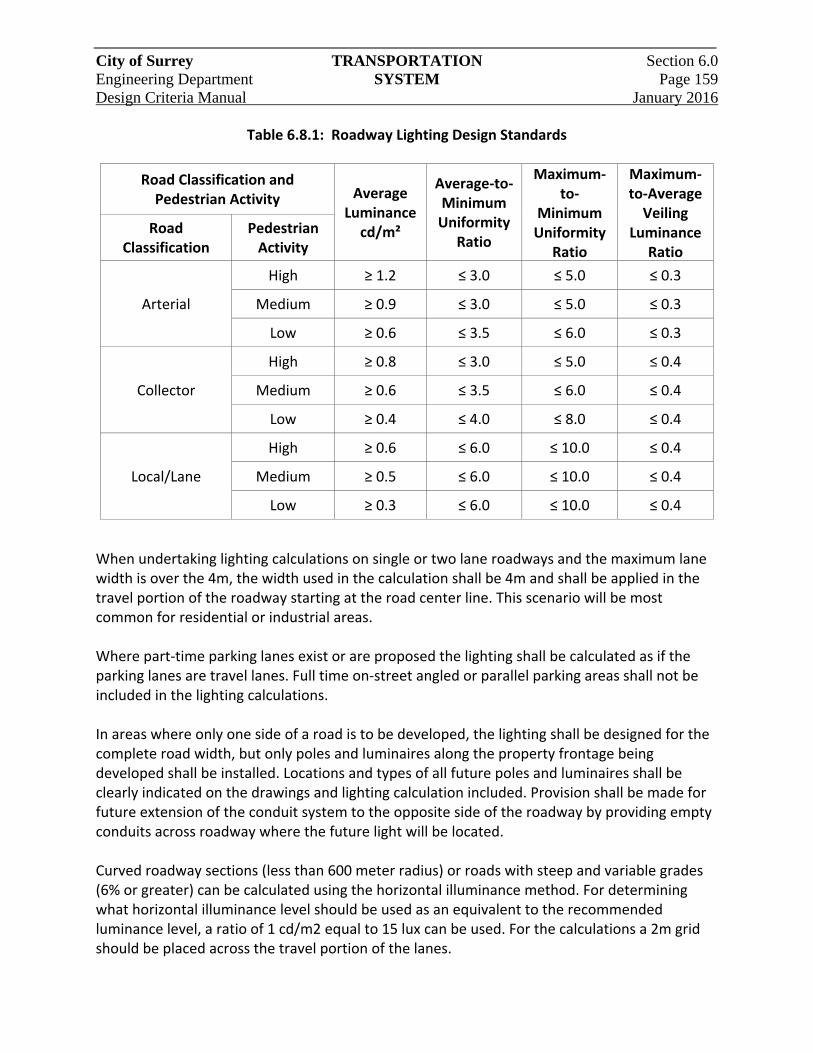
City of Surrey TRANSPORTATION Section 6.0 Engineering Department SYSTEM Page 159 Design Criteria Manual January 2016
Table 6.8.1: Roadway Lighting Design Standards
Road Classification and Pedestrian Activity Average
Luminance cd/m²
Average‐to‐Minimum Uniformity
Ratio
Maximum‐to‐
Minimum Uniformity
Ratio
Maximum‐to‐Average Veiling
Luminance Ratio
Road Classification
Pedestrian Activity
Arterial
High ≥ 1.2 ≤ 3.0 ≤ 5.0 ≤ 0.3
Medium ≥ 0.9 ≤ 3.0 ≤ 5.0 ≤ 0.3
Low ≥ 0.6 ≤ 3.5 ≤ 6.0 ≤ 0.3
Collector
High ≥ 0.8 ≤ 3.0 ≤ 5.0 ≤ 0.4
Medium ≥ 0.6 ≤ 3.5 ≤ 6.0 ≤ 0.4
Low ≥ 0.4 ≤ 4.0 ≤ 8.0 ≤ 0.4
Local/Lane
High ≥ 0.6 ≤ 6.0 ≤ 10.0 ≤ 0.4
Medium ≥ 0.5 ≤ 6.0 ≤ 10.0 ≤ 0.4
Low ≥ 0.3 ≤ 6.0 ≤ 10.0 ≤ 0.4
When undertaking lighting calculations on single or two lane roadways and the maximum lane width is over the 4m, the width used in the calculation shall be 4m and shall be applied in the travel portion of the roadway starting at the road center line. This scenario will be most common for residential or industrial areas. Where part‐time parking lanes exist or are proposed the lighting shall be calculated as if the parking lanes are travel lanes. Full time on‐street angled or parallel parking areas shall not be included in the lighting calculations. In areas where only one side of a road is to be developed, the lighting shall be designed for the complete road width, but only poles and luminaires along the property frontage being developed shall be installed. Locations and types of all future poles and luminaires shall be clearly indicated on the drawings and lighting calculation included. Provision shall be made for future extension of the conduit system to the opposite side of the roadway by providing empty conduits across roadway where the future light will be located. Curved roadway sections (less than 600 meter radius) or roads with steep and variable grades (6% or greater) can be calculated using the horizontal illuminance method. For determining what horizontal illuminance level should be used as an equivalent to the recommended luminance level, a ratio of 1 cd/m2 equal to 15 lux can be used. For the calculations a 2m grid should be placed across the travel portion of the lanes.
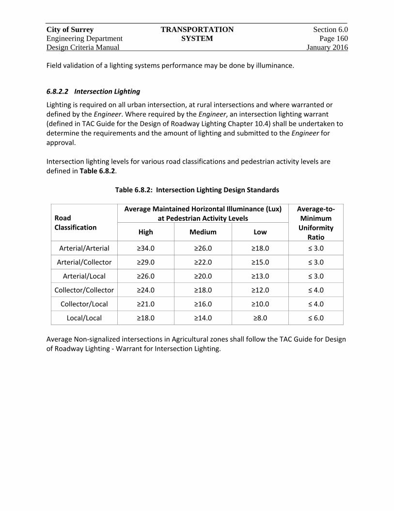
City of Surrey TRANSPORTATION Section 6.0 Engineering Department SYSTEM Page 160 Design Criteria Manual January 2016
Field validation of a lighting systems performance may be done by illuminance.
6.8.2.2 Intersection Lighting
Lighting is required on all urban intersection, at rural intersections and where warranted or defined by the Engineer. Where required by the Engineer, an intersection lighting warrant (defined in TAC Guide for the Design of Roadway Lighting Chapter 10.4) shall be undertaken to determine the requirements and the amount of lighting and submitted to the Engineer for approval. Intersection lighting levels for various road classifications and pedestrian activity levels are defined in Table 6.8.2.
Table 6.8.2: Intersection Lighting Design Standards
Road Classification
Average Maintained Horizontal Illuminance (Lux) at Pedestrian Activity Levels
Average‐to‐Minimum Uniformity
RatioHigh Medium Low
Arterial/Arterial ≥34.0 ≥26.0 ≥18.0 ≤ 3.0
Arterial/Collector ≥29.0 ≥22.0 ≥15.0 ≤ 3.0
Arterial/Local ≥26.0 ≥20.0 ≥13.0 ≤ 3.0
Collector/Collector ≥24.0 ≥18.0 ≥12.0 ≤ 4.0
Collector/Local ≥21.0 ≥16.0 ≥10.0 ≤ 4.0
Local/Local ≥18.0 ≥14.0 ≥8.0 ≤ 6.0
Average Non‐signalized intersections in Agricultural zones shall follow the TAC Guide for Design of Roadway Lighting ‐ Warrant for Intersection Lighting.
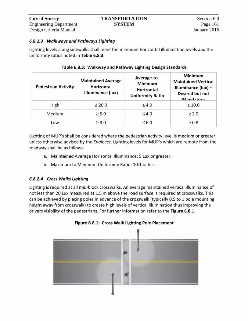
City of Surrey TRANSPORTATION Section 6.0 Engineering Department SYSTEM Page 161 Design Criteria Manual January 2016
6.8.2.3 Walkways and Pathways Lighting
Lighting levels along sidewalks shall meet the minimum horizontal illumination levels and the uniformity ratios noted in Table 6.8.3.
Table 6.8.3: Walkway and Pathway Lighting Design Standards
Pedestrian Activity Maintained Average
Horizontal Illuminance (lux)
Average‐to‐Minimum Horizontal
Uniformity Ratio
Minimum Maintained Vertical Illuminance (lux) – Desired but not Mandatory
High ≥ 20.0 ≤ 4.0 ≥ 10.0
Medium ≥ 5.0 ≤ 4.0 ≥ 2.0
Low ≥ 3.0 ≤ 6.0 ≥ 0.8
Lighting of MUP’s shall be considered where the pedestrian activity level is medium or greater unless otherwise advised by the Engineer. Lighting levels for MUP’s which are remote from the roadway shall be as follows:
a. Maintained Average Horizontal Illuminance: 5 Lux or greater.
b. Maximum to Minimum Uniformity Ratio: 10:1 or less.
6.8.2.4 Cross Walks Lighting
Lighting is required at all mid‐block crosswalks. An average maintained vertical illuminance of not less than 20 Lux measured at 1.5 m above the road surface is required at crosswalks. This can be achieved by placing poles in advance of the crosswalk (typically 0.5 to 1 pole mounting height away from crosswalk) to create high levels of vertical illumination thus improving the drivers visibility of the pedestrians. For further information refer to the Figure 6.8.1.
Figure 6.8.1: Cross Walk Lighting Pole Placement
City of Surrey TRANSPORTATION Section 6.0 Engineering Department SYSTEM Page 162 Design Criteria Manual January 2016
6.8.2.5 Roundabout Lighting
Roundabouts have more complex visibility considerations than typical intersections. The effectiveness of motor vehicle headlights are limited in a roundabout due to the constrained curve radius, making the street lighting system a necessity to aid in the nighttime visibility of obstructions, hazards and pedestrians in crosswalks. Lighting in roundabouts shall be designed for illuminance and uniformity equivalent to Arterial/Arterial Intersections. Lighting levels in crosswalks within the roundabout shall meet vertical lighting levels listed for crosswalks. Where there is no lighting on the approach street lighting should be added on the approach roads for a distance of approximately 80 m from the roundabout crosswalks.
6.8.3 Pole Layout and Spacing
All poles shall be davit style, unless decorative poles are requested by the Engineer. Davit pole heights shall be 7.5m and 9.0m. Taller poles, 11.0m or 13.5m high, can be use on arterial roadways only with the City’s approval. Poles along the roadway shall be located at the outer edges behind curb and gutter or edge of pavement, or in special circumstances, in the median of the street. Where median lighting is being considered the lighting levels on any sidewalks shall be met or additional supplemental sidewalk lighting maybe required. The exact offset of the pole (behind curb, edge of pavement or sidewalk) is typically defined on City’s Standard Detail Drawings. Poles at intersections shall be located to accommodate intersections, property corners and pedestrian walkways. Spacing shall be governed by roadway width, road configuration and intersecting property lines. Locate pole at curb returns, at property lines and clear of driveways and wheelchair ramps. Pole spacing patterns include staggered, opposite, one side and median mount arrangements, depending on the roadway classification and road geometrics. The pole arrangements shall generally be as follows:
a. Roads 8.5m and narrower – One sided spacing
b. Roads over 8.5m wide – Staggered or opposite spacing
c. One sided spacing may be allowed when power line clearances can’t be met.
d. Poles can be located in medians if a clearance of 0.5m from the pole to curb face can be maintained and posted speed is 60 km/h or less. A minimum of 2 consecutive poles should be required before considering poles in islands.
e. Maintain clearances of 3.0 m from overhead 25kV primary power lines to luminaires.
City of Surrey TRANSPORTATION Section 6.0 Engineering Department SYSTEM Page 163 Design Criteria Manual January 2016
Where trees are proposed lights may have to be installed on davit arms which extend out over the roadway beyond the ultimate tree canopy. Additional pedestrian scale lighting may be required for the sidewalk. The proposed locations, spacing, pole height, arm length and frequency of the trees may also need to be adjusted in conjunction with the lighting pole spacing. A tighter pole spacing than calculated may be required to compensate for anticipated light blockage resulting in additional poles and luminaires. Where trees exist and impact the lighting tree pruning shall be considered.
6.8.4 Decorative Street Lighting
The City has designated Unique Designated Areas, NCP Areas and Town Centres in which Decorative Street Lighting is utilized to enhance the streetscape. Decorative poles maybe defined for various areas, and the poles may have specific shapes, colour and styles along with banners and flower basket hangers. Decorative poles shall be 6.0m or 7.5m high. Decorative poles may be suitable for roadways not exceeding 11 m width. Where decorative poles are required the poles and anchor bolts shall meet all applicable codes and standards. The Engineer shall provide the Developer with generic details of the decorative LED lighting requirements and a list of approved suppliers for use in producing design drawings. The following details are required as part of the decorative lighting design:
a. Shop drawings of the street light poles proposed complete with pole design criteria, sealed by the Engineer, registered in the Province of B.C.;
b. Detailed information and specifications of the luminaires proposed;
c. Detailed information on pole accessories (decorative bases, banner arms, receptacles, etc.);
d. Drawings detailing assembled pole and luminaire units; and
e. Full size design drawings detailing the complete site installation.
6.8.5 Design Calculations
Lighting design requires a computer lighting design software such as AGI32 or Visual Roadway and lighting supplier photometric files from lighting suppliers in the IESNA format. Typically luminaire photometric files are based on a lamp which can vary from actual lamp used in the test, provided it similar. This referred to as “relative” photometry. For LED photometric files must be “absolute” which means the photometric file must be for the exact luminaire being tested.
City of Surrey TRANSPORTATION Section 6.0 Engineering Department SYSTEM Page 164 Design Criteria Manual January 2016
The designer shall select luminaires with optical systems which efficiently light the interned area and properly illuminate the roadway and sidewalks as well as provide maximum spill light control beyond the sidewalk in order to reduce spill light and glare impacts on local residents. This shall be done by analyzing luminaire optical systems using the BUG method defined in Illuminating Engineering Society TM‐15 Classification System for Outdoor Luminaires and Addendum A: Backlight, Uplight, and Glare (BUG) Ratings. The maximum nominal BUG rating of luminaires shall be B2‐U1‐G2 however lower BUG rating should be used where possible. The designer shall apply Light Loss Factor to the lighting design. For LED's the Light Loss Factor (LLF) is a combination of several factors representing deterioration of the lamp and luminaire over their life‐spans which is applied to a lighting design. Several individual factors combine to form the overall LLF. The LLF then is incorporated into the design calculations.
LLF = LLD x LDD x LATF
Where: Lamp Lumen Depreciation (LLD) = 0.85. Luminaire Dirt Depreciation (LDD) = 0.90 Luminaire Ambient Temperature Factor (LATF) = 1.04 (+10° C).
For LED's the range of LLF shall be 0.8. Electrical design requirements include:
a. Maximum voltage drop for branch circuits: 3%.
b. Allow for possibility of future expansion. Stub out conduit(s) at the last streetlight pole and / or into a temporary junction box at end of the development.
c. Type 37 concrete junction boxes shall be installed where required.
d. 1‐75mm RPVC traffic signal interconnection conduit in conjunction with roadway lighting for all Arterial and Collector Roads. The conduit shall be common trenched with the street lighting system conduit.
e. All empty conduits shall have a 6 mm nylon pull string installed and capped ends.
f. Conductor sizes: #4 RW90 aluminum in conduit and #10 RW90 copper in the poles from luminaire to the pole handhole. All street lighting feeder conductors shall be stranded 3 conductor (3c) aluminum (al) c/w insulated bond, Surrey specifications with City of Surrey marking (Alcan Nual Feederplex HS RW90 or Southwire Aluminum Simpull RW90 Quadruplex or City of Surrey approved equivalent). Size of conductors as noted. Circuit load not to exceed 80% of feeder breaker rating (as per CEC).
g. Where required, include loads for pole receptacles (100 W/receptacle for LED’s), tree lights, traffic signal controllers and other devices connected to the service panel
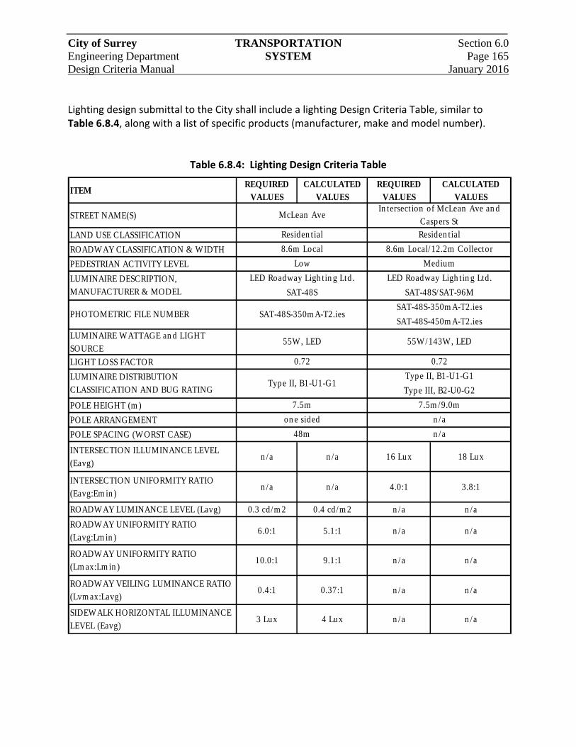
City of Surrey TRANSPORTATION Section 6.0 Engineering Department SYSTEM Page 165 Design Criteria Manual January 2016
Lighting design submittal to the City shall include a lighting Design Criteria Table, similar to Table 6.8.4, along with a list of specific products (manufacturer, make and model number).
Table 6.8.4: Lighting Design Criteria Table
ITEMREQUIRED
VALUESCALCULATED
VALUESREQUIRED
VALUESCALCULATED
VALUES
STREET NAME(S)
LAND USE CLASSIFICATION
ROADWAY CLASSIFICATION & WIDTH
PEDESTRIAN ACTIVITY LEVEL
LUMINAIRE WATTAGE an d LIGHT SOURCE
LIGHT LOSS FACTOR
POLE HEIGHT (m )
POLE ARRANGEMENT
POLE SPACING (WORST CASE)
INTERSECTION ILLUMINANCE LEVEL (Eavg)
n /a n /a 16 Lux 18 Lux
INTERSECTION UNIFORMITY RATIO (Eavg:Em in )
n /a n /a 4.0:1 3.8:1
ROADWAY LUMINANCE LEVEL (Lavg) 0.3 cd/m 2 0.4 cd/m 2 n /a n /a
ROADWAY UNIFORMITY RATIO (Lavg:Lm in )
6.0:1 5.1:1 n /a n /a
ROADWAY UNIFORMITY RATIO (Lm ax:Lm in )
10.0:1 9.1:1 n /a n /a
ROADWAY VEILING LUMINANCE RATIO (Lvm ax:Lavg)
0.4:1 0.37:1 n /a n /a
SIDEWALK HORIZONTAL ILLUMINANCE LEVEL (Eavg)
3 Lux 4 Lux n /a n /a
55W/143W, LED
0.72
n /a
Type III, B2-U0-G2
Type II, B1-U1-G1
n /a
on e sided
48m
7.5m
Medium
SAT-48S-350m A-T2.ies
SAT-48S/SAT-96M
SAT-48S-350m A-T2.ies
SAT-48S
55W, LED
0.72
SAT-48S-450m A-T2.ies
LUMINAIRE DESCRIPTION, MANUFACTURER & MODEL
LED Roadway Ligh tin g Ltd. LED Roadway Ligh t in g Ltd.
In tersect ion of McLean Ave an d Caspers St
PHOTOMETRIC FILE NUMBER
7.5m /9.0m
McLean Ave
Residen t ial
8.6m Local
Low
LUMINAIRE DISTRIBUTION CLASSIFICATION AND BUG RATING
Type II, B1-U1-G1
Residen tial
8.6m Local/12.2m Collector

City of Surrey TRANSPORTATION Section 6.0 Engineering Department SYSTEM Page 166 Design Criteria Manual January 2016
6.8.6 Power Supply and Distribution
Power is generally supplied by BC Hydro through an un‐metered service when servicing only streetlights and traffic signals. Where tree lights and pole receptacles are included, BC Hydro may require a metered service. This shall be confirmed with the City and BC Hydro. The designer shall confirm voltage and locations of suitable power sources for the proposed lighting system. The designer shall confirm if a new service is required or an existing lighting system in the area is suitable for extension. Lighting systems are typically serviced from a 120/240 Volt single phase 3 wire system. Use of other voltages must meet City approval. Services are to be “Underground Dip” type or will tie into a service box. The designer shall select a suitable service location based on availability and what meets the City and BC Hydro standards. The BC Hydro power supply shall feed into a service base which shall contain panel boards, breakers, lighting contactor(s) and switch. The lighting is controlled by a single photocell located on a luminaire. The service base shall be located:
a. • Off the roadway where not likely to be impacted by motor vehicles;
b. • Where it will not be a hazard or obstruction to pedestrians;
c. • Where it can be accessed for easy servicing;
d. • To accommodate extension to future lights.
Power distribution requirements include:
a. Wiring to be installed in minimum 35mm Rigid PVC conduit.
b. Wiring to be stranded aluminum with RW90 insulation.
c. Wiring to be colour coded per Canadian Electrical Code (CEC).
d. Conduit burial depth as per City Standards.
Conduit alignments shall be designed to avoid tree roots.
City of Surrey TRANSPORTATION Section 6.0 Engineering Department SYSTEM Page 167 Design Criteria Manual January 2016
6.9 Traffic Signals and Control
Traffic signal details are standardized throughout British Columbia to avoid potential confusion of the travelling public, both local and visiting. They are defined in the BC Motor Vehicle Act. Items standardized include:
a. Vertical mounted signal heads
b. Left side secondary heads
c. Order of signal indication.
The Standard Construction documents shall be used in conjunction with the B.C. Motor Vehicle Act Regulations ‐ Division (23) Traffic Control Devices and the B.C. Motor Vehicle Act R.S.B.C. 1996, Chapter 318. Refer to Part B, Traffic Signals, of the most current edition of the Manual of Uniform Traffic Control Devices for Canada (MUTCD) for information on traffic signal specifications, concepts and terminology.
6.9.1 Signal Heads
General locations of signal heads are as follows:
a. Primary: Mounted over the roadway which a vehicle is to enter
b. Secondary: Mounted to the left of the roadway which a vehicle is to enter
c. Auxiliary: Mounted to the right of the primary head, or other location to enhance visibility
d. Pedestrian: Mounted on the far side of the intersection in line with the painted crosswalk.
Signal visibility distance is defined as the distance in advance of the stop line from which a signal must be continuously visible for approach speeds varying between 40 and 80 km/h. For speeds exceeding 80 km/h, the minimum visibility distance must equal or exceed the minimum stopping sight distance. Visibility distance guidelines are shown in Table 6.9.1.
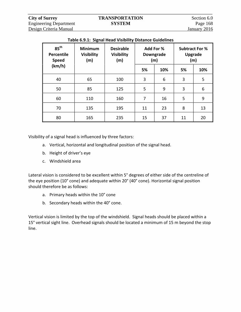
City of Surrey TRANSPORTATION Section 6.0 Engineering Department SYSTEM Page 168 Design Criteria Manual January 2016
Table 6.9.1: Signal Head Visibility Distance Guidelines
85th Percentile Speed (km/h)
Minimum Visibility
(m)
Desirable Visibility
(m)
Add For % Downgrade
(m)
Subtract For %
Upgrade (m)
5% 10%
5% 10%
40 65 100 3 6
3 5
50
85 125 5 9
3 6
60
110 160 7 16
5 9
70
135 195 11 23
8 13
80
165 235 15 37
11 20
Visibility of a signal head is influenced by three factors:
a. Vertical, horizontal and longitudinal position of the signal head.
b. Height of driver’s eye
c. Windshield area
Lateral vision is considered to be excellent within 5° degrees of either side of the centreline of the eye position (10° cone) and adequate within 20° (40° cone). Horizontal signal position should therefore be as follows:
a. Primary heads within the 10° cone
b. Secondary heads within the 40° cone.
Vertical vision is limited by the top of the windshield. Signal heads should be placed within a 15° vertical sight line. Overhead signals should be located a minimum of 15 m beyond the stop line.
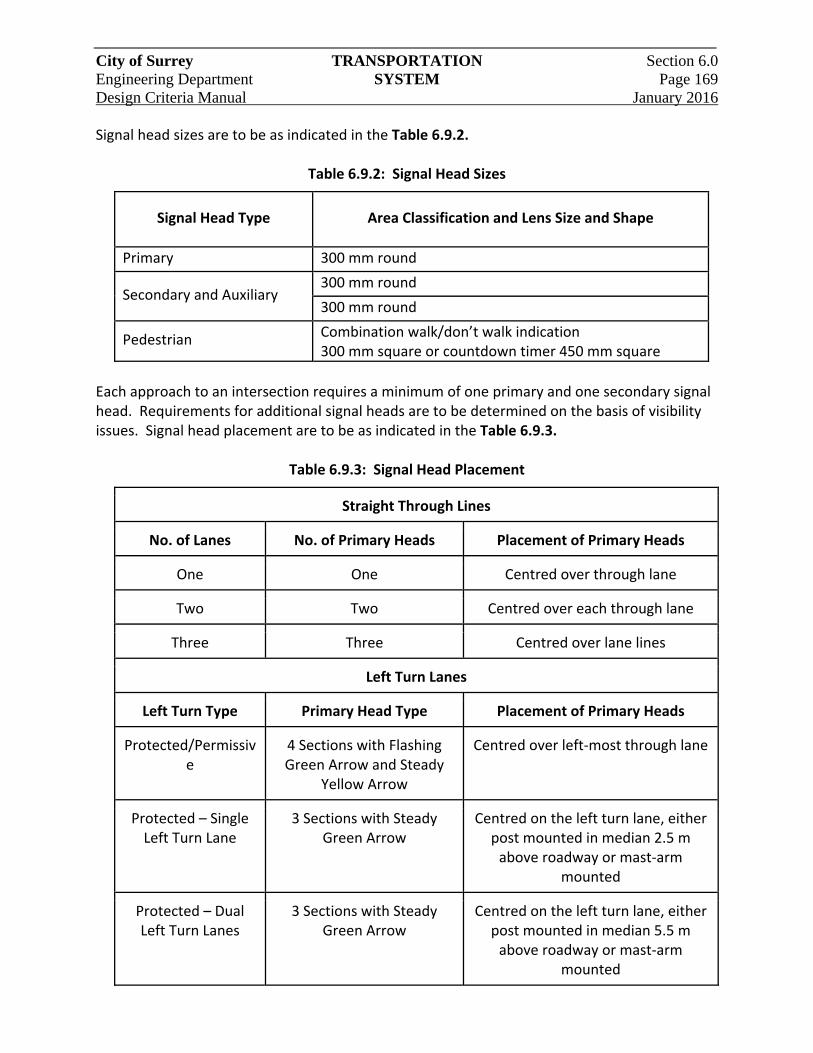
City of Surrey TRANSPORTATION Section 6.0 Engineering Department SYSTEM Page 169 Design Criteria Manual January 2016
Signal head sizes are to be as indicated in the Table 6.9.2.
Table 6.9.2: Signal Head Sizes
Signal Head Type Area Classification and Lens Size and Shape
Primary 300 mm round
Secondary and Auxiliary 300 mm round
300 mm round
Pedestrian Combination walk/don’t walk indication 300 mm square or countdown timer 450 mm square
Each approach to an intersection requires a minimum of one primary and one secondary signal head. Requirements for additional signal heads are to be determined on the basis of visibility issues. Signal head placement are to be as indicated in the Table 6.9.3.
Table 6.9.3: Signal Head Placement
Straight Through Lines
No. of Lanes No. of Primary Heads Placement of Primary Heads
One One Centred over through lane
Two Two Centred over each through lane
Three Three Centred over lane lines
Left Turn Lanes
Left Turn Type Primary Head Type Placement of Primary Heads
Protected/Permissive
4 Sections with Flashing Green Arrow and Steady
Yellow Arrow
Centred over left‐most through lane
Protected – Single Left Turn Lane
3 Sections with Steady Green Arrow
Centred on the left turn lane, either post mounted in median 2.5 m above roadway or mast‐arm
mounted
Protected – Dual Left Turn Lanes
3 Sections with Steady Green Arrow
Centred on the left turn lane, either post mounted in median 5.5 m above roadway or mast‐arm
mounted
City of Surrey TRANSPORTATION Section 6.0 Engineering Department SYSTEM Page 170 Design Criteria Manual January 2016
6.9.2 Pole Placement
Signal poles should be placed between 1m and 3m from the face of curb or edge of pavement, preferably behind the sidewalk. Pole arms should be oriented at 90° to the centreline of the road, except where the intersection is skewed. When laying out a skewed intersection, ensure the arms do not block the view of the signal heads for other approaches. Other key considerations for pole placement are:
a. Ease of access to pushbutton for pedestrians, handicapped and the visually impaired.
b. Maintaining wheelchair access around poles and from pushbuttons to wheelchair ramps.
c. Minimizing the number of poles required.
d. Locating poles outside vehicle turning radius’s to avoid damage.
e. Underground and overhead utility conflicts.
f. For better visibility of vehicle and pedestrian heads
The City’s Specifications define typical bases to go with standard signals poles. The designer is responsible for determining the suitability of these standard foundations for the given soil’s conditions. Where soils are in question a geotechnical engineer should be consulted to define the suitability of the foundations for the given soil’s conditions. Where foundations are not suitable, custom foundations will be required.
6.9.3 Left Turn Phasing
Left turns at signalized phasing options are as follows:
a. Permissive – Green ball display. A Permissive left turn has no signal indication other than a green ball, which permits a left turn when opposing traffic is clear.
b. Protected – Green arrow display. A Protected left turn presents a continuous green arrow indication while all opposing traffic is held by a red ball. A Protected Left Turn is always terminated with a yellow ball.
c. Protected/Permissive – Yellow/Flashing Green arrow display. A Protected/Permissive left turn presents a flashing green arrow followed by a green ball. During the flashing phase (advanced movement), opposing through traffic is held by a red ball. After the advance has timed out, left turn traffic is presented with a green ball permitting the movement when conflicting traffic is clear. The protected phase of this movement is always terminated with a non‐flashing yellow arrow indication.
City of Surrey TRANSPORTATION Section 6.0 Engineering Department SYSTEM Page 171 Design Criteria Manual January 2016
Protected/Permissive left turns phasing shall be used however protected left turn phasing can be considered for: dual left turn lanes; lack of sight distance to oncoming vehicle; high speeds; and left turn phase is in a lead‐lag operation.
6.9.4 Signal and Pre‐Emption
Traffic signals in close proximity to rail crossings require interconnection with the rail crossing controls to ensure maximum driver safety. Where the City require emergency vehicle pre‐emption to override normal signal operation and provide continuous green signals for emergency vehicles such as fire department equipment and ambulances. The Cities emergency vehicle pre‐emption system operates by the use of strobe lights (Opticom).
6.9.5 Audible Pedestrian Signals
Where required by the Engineer, use audible pedestrian signals to assist visually impaired pedestrians. The audible signal is interconnected with the Walk signal, and produces a “cuckoo” or “peep” sound, depending on the direction of crossing. The cuckoo sound is used for north‐south crossings and the peep is used for east‐west crossings. Where the streets are not oriented north‐south and east‐west, maintain consistency with adjacent signals.
6.9.6 Controllers and Cabinets
Controller cabinets are available in various sizes and styles depending on equipment requirements. The City’s Specifications define cabinet and base sizes and installation methods. Cabinets should be located entirely within the road right‐of‐way, including maintenance pad and door swing. Location should be behind the sidewalk, with access door on the side away from the sidewalk and the signals visible from the access. Cabinets should be NEMA 3R rated heavy gauge aluminum with grey powder coat exterior finish unless otherwise directed by the local authority. Traffic signal controllers should be model 170 and shall be supplied by the City.
City of Surrey TRANSPORTATION Section 6.0 Engineering Department SYSTEM Page 172 Design Criteria Manual January 2016
6.9.7 Power Supply and Distribution
6.9.7.1 General and Conduit
The designer shall confirm voltage and locations of suitable power sources for the proposed signal system. Signals systems are typically serviced from a 120/240 Volt single phase 3 wire system. Alternately, 120/208 volt 3 phase 4 wire systems may be used if necessary and if approved by the Engineer. Signal wiring and conduit shall include a minimum of 1‐53 RPVC conduits and 2 ‐78mm RPVC around at all four corners of the intersection (1‐78 for signal cables, 1 – 78 for loops and 1‐53 for lighting and power conductors). A type 5 concrete junction boxes shall be provided at each corner of the intersection. 6.9.7.2 Uninterruptible Power Supplies (UPS’s)
UPS’s shall be considered where power outages are a concern or intersection is in high collision or high risk area. UPS’s may mount on the traffic controller cabinet. The duration of operation flash period during a power failure will define the UPS size and number of batteries required. The use of UPS shall be confirmed with the City
SECTION 7
Unique Designated Areas
City of Surrey UNIQUE DESIGNATEED AREAS Section 7.0 Engineering Department Page 173 Design Criteria Manual January 2016
7 UNIQUE DESIGNATED AREAS
7.1 General Supplementary Requirements for “Unique Designated Areas”
7.1.1 General
The City has designated several areas of the municipality as special Unique Areas that warrant special infrastructure services or non‐standard levels of service. Prior to undertaking land development or the design of services in these areas the Developer and/or Consultant will meet with and confirm with the Engineer all requirements and levels of services expected. These areas have particular criteria included in this Section and in the Standard Drawings.
7.2 Bridgeview ‐ South Westminster Requirements
7.2.1 Area
The area for Bridgeview ‐ South Westminster is delineated on Standard Drawing SSD‐U.1.
7.2.2 Sanitary Sewers
Due to unique peat soil conditions, the Bridgeview ‐ South Westminster area of Surrey has been serviced, in the past, by a sanitary vacuum sewer system. This system is not to be extended and will be replaced over time by a “steep grade sanitary sewer system” in Bridgeview and by Low Pressure Sewer System (LPS) in South Westminster. No new connection will be allowed to existing vacuum sewer system 7.2.2.1 Steep Grade Sanitary Sewer System
All sewers including Service Connections should be PVC DR18 with a minimum grade of 1.0% for upper sections (less than 2m depth) and 0.8% for lower sections (greater than 2m depth) for local sewers and 2% grade for Service Connections. HDPE pipes may be permitted together with direction drilling, if approved by the Engineer. Geotechnical Engineering review is required for the design of the steep grade sewer system.
7.2.3 Road Sections
Typical road sections are shown on the Standard Drawing SSD‐U.1.2. Typical driveway crossings are shown in Standard Drawings SSD‐U.1.3 and SSD‐U.1.4.
City of Surrey UNIQUE DESIGNATEED AREAS Section 7.0 Engineering Department Page 174 Design Criteria Manual January 2016
7.3 West Panorama Ridge Requirements
7.3.1 Area
The area for West Panorama Ridge is delineated on the Drawing SSD‐U.2.
7.3.2 Road Sections
Typical road sections are shown on the Drawings SSD‐U.2.1 and SSD‐U.2.2 for Collector and Local Roads, respectively. West Panorama Ridge Area: 100 Watt post top street lights required only at intersections of Arterial and Collector Roads. No streetlights will be installed in other locations unless approved by the Engineer. (See Table 6.4.1) Drainage Infiltration trench requirements are shown on Drawing SSD‐U.2.3.
7.4 Surrey City Centre Requirements
7.4.1 Area
The area for Surrey City Centre is delineated on the Drawing SSD‐U.3.
7.4.2 Road Sections
Specific load sections and details for Surrey City Centre are to be obtained from the Engineer. City Centre Street lighting will adhere to current City Centre specifications.
7.5 Central Semiahmoo Requirements
7.5.1 Area
The area for Central Semiahmoo is delineated on the Drawing SSD‐U.4.
7.5.2 Roadworks System
Specific roadworks system details for Central Semiahmoo are shown on the DrawingsSSD‐U.4.1 to SSD‐U.4.3. Street lighting will be post top style on Local Roads in the Central Semiahmoo NCP.