Design Criteria for LP BYPASS SYSTEM. LP Bypass system provide a very effective means of controlling...
25
Design Criteria for LP BYPASS SYSTEM
-
Upload
emory-norman -
Category
Documents
-
view
243 -
download
2
Transcript of Design Criteria for LP BYPASS SYSTEM. LP Bypass system provide a very effective means of controlling...
Design Criteria for
LP BYPASS SYSTEM
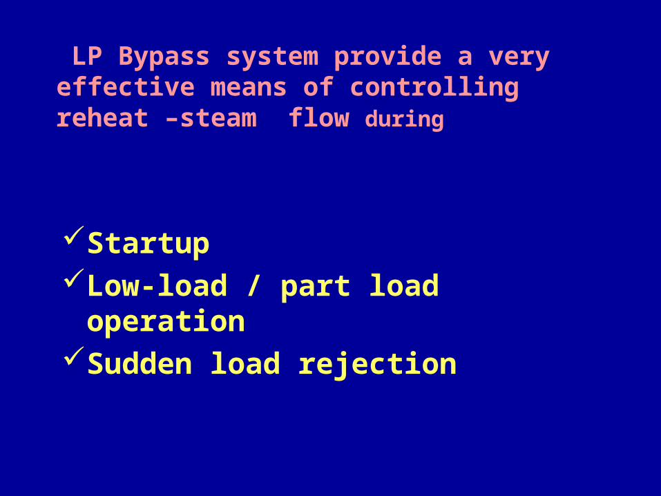
LP Bypass system provide a very effective means of controlling reheat –steam flow during
Startup Low-load / part load operationSudden load rejection

It enhances fast starting capability of turbines from all initial conditions e.g.
Cold condition Warm condition Hot Condition
LP steam-bypass system operate in parallel with the turbine
Protect Condenser from excessive temperature and pressure that
could result from sudden injection of superheated steam
Ensure coordinated control between HP and IP turbine control valves and the steam bypass systems to operate at any remaining load
Subsequently reloaded in a controlled manner
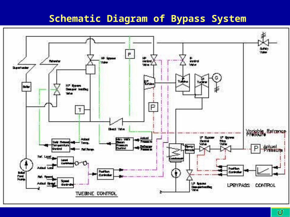
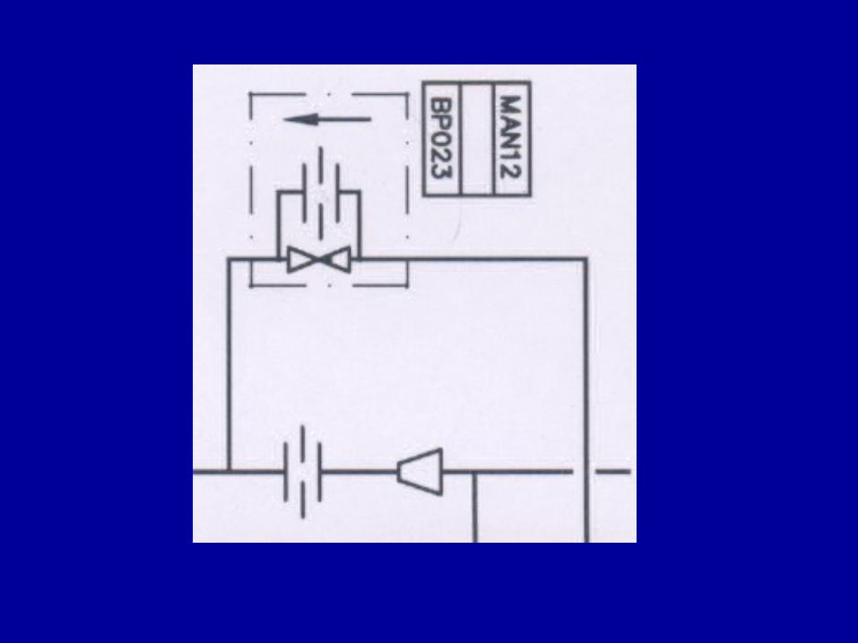
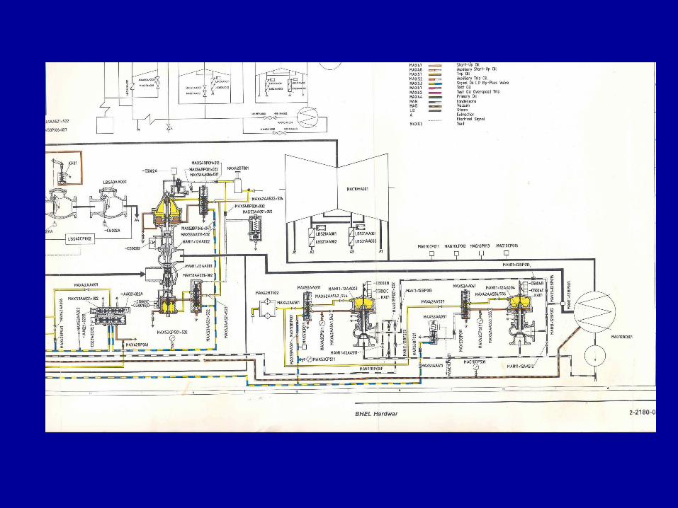
Schematic Diagram of Bypass System
• The controls for LP Bypass system are combination of electrical and well proven hydraulic system
• Electro-hydraulic converter provides the necessary link between hydraulic actuator and electrical system
• The LPBypass Controller acts as a maximum pressure Controller
• It regulates the reheater pressure either to the fixed set value or suitably derived variable set value
• If the reheater pressure exceeds this set value, the Controller causes the electro-hydraulic converter to operate and initiate bypass operation
Set Value formation
The Two set values – fixed and variable are formed for the LPBypass control systemset value to be used is determined by a maximum value selectorFor the formation of variable set point, a pressure transducer is used to measure the steam pressure in HP turbine
SEQUENCE OF EVENTS RESULTING FROM LOAD REJECTION
Upon receiving load rejection signal from electrical system:
Turbine Speed Controller assumes control of the TG set
It initiates fast closure of HP & IP turbine control valves through position controller
Fast closure of turbine control valves cause an immediate decrease in HP 1st. Stage pressure
SEQUENCE OF EVENTS RESULTING FROM LOAD REJECTION
Pressure increases in main and reheat steam systems
These pressure changes are sensed by HP and LP Bypass controllers
Respective bypass valves are opened
If LP steam- bypass system fails or the condenser cannot
accept LP bypass steam , Safety Valves open and dump
steam to atmosphere
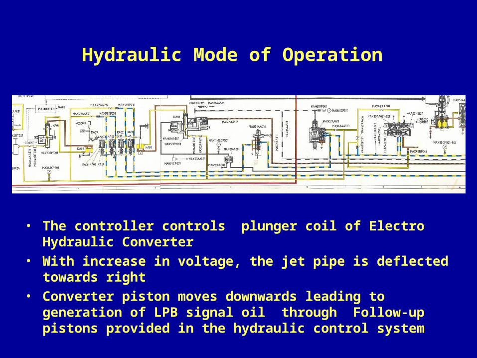
Hydraulic Mode of Operation
• The controller controls plunger coil of Electro Hydraulic Converter
• With increase in voltage, the jet pipe is deflected towards right
• Converter piston moves downwards leading to generation of LPB signal oil through Follow-up pistons provided in the hydraulic control system
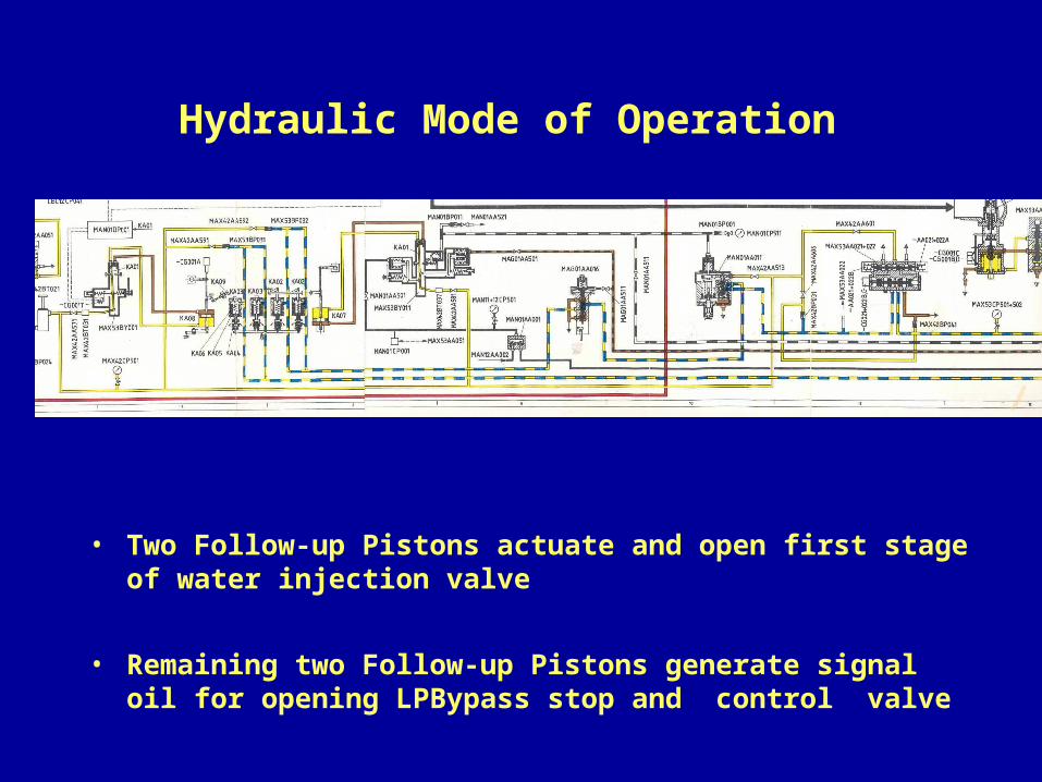
Hydraulic Mode of Operation
• Two Follow-up Pistons actuate and open first stage of water injection valve
• Remaining two Follow-up Pistons generate signal oil for opening LPBypass stop and control valve

ADJUSTMENT OF
LPBYPASS CONVERTER
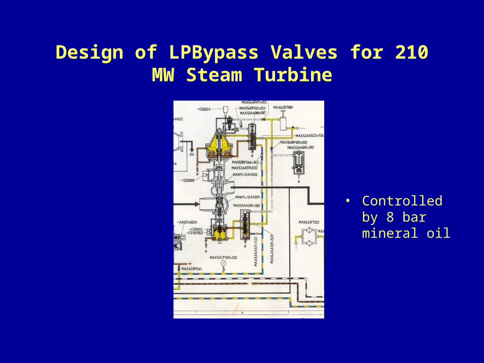
Design of LPBypass Valves for 210 MW Steam Turbine
• Controlled by 8 bar mineral oil
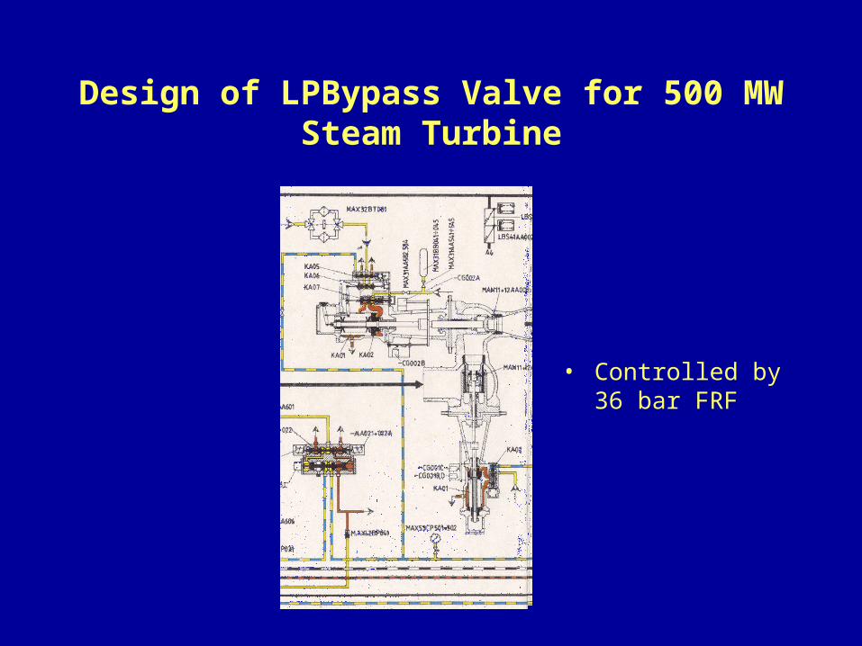
Design of LPBypass Valve for 500 MW Steam Turbine
• Controlled by 36 bar FRF
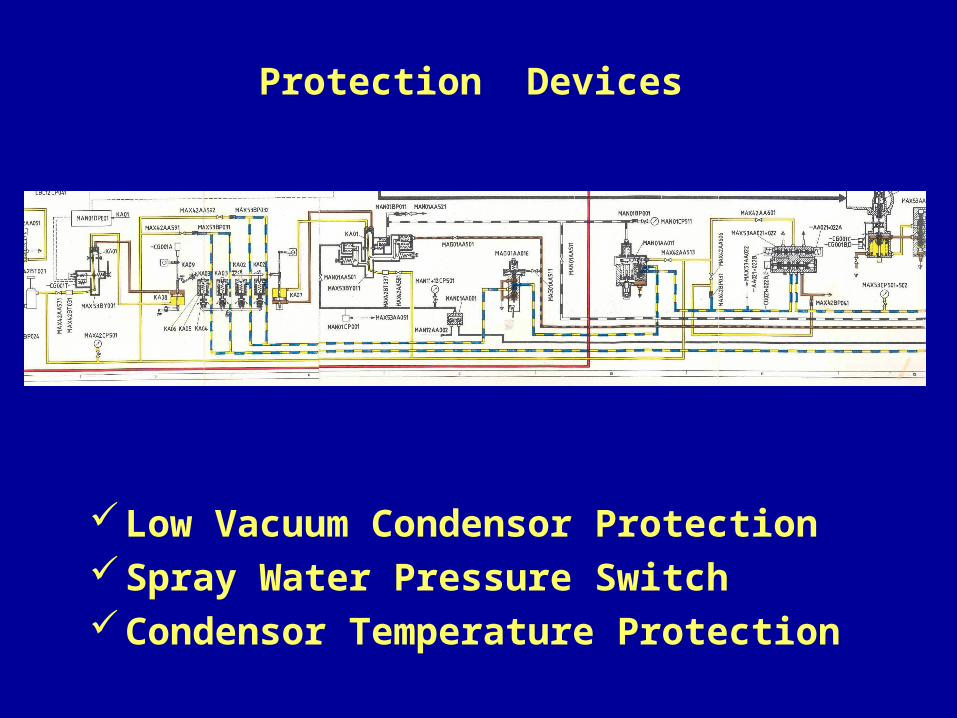
Protection Devices
Low Vacuum Condensor ProtectionSpray Water Pressure SwitchCondensor Temperature Protection
Protection Devices cause closure of bypass station in case of following
eventualities
a) Condensor vacuum is low ( > 0.6 bar absolute )
b) Spray water pressure is low (< 8.5 / 9.5 bar )
c) Temperature of condenser body is high (> 90° C )
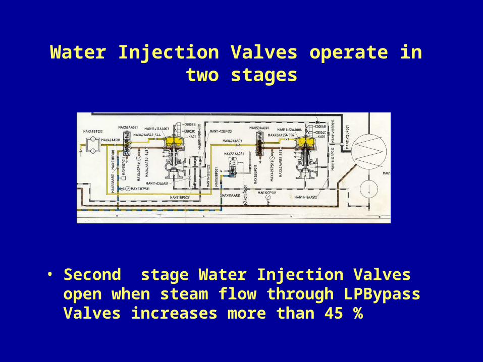
Water Injection Valves operate in two stages
• Second stage Water Injection Valves open when steam flow through LPBypass Valves increases more than 45 %
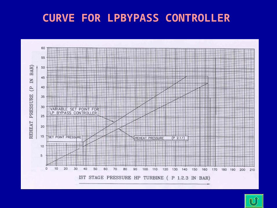
CURVE FOR LPBYPASS CONTROLLER
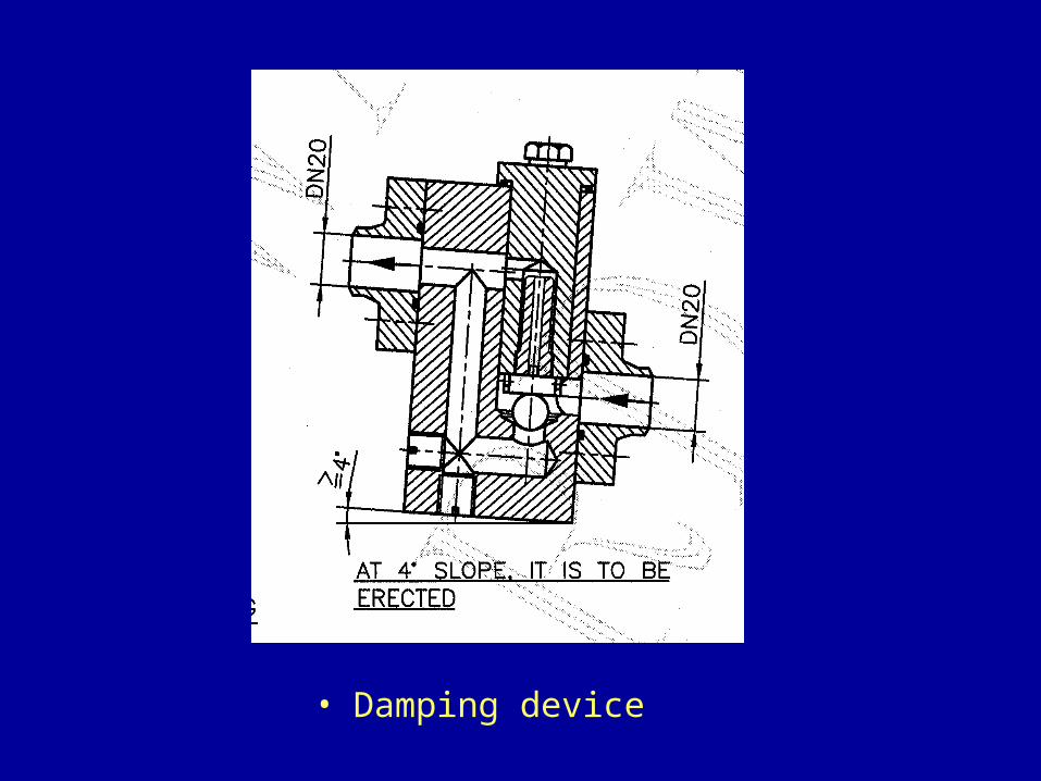
• Damping device