Fatigue Life Calculation of Welded Joints Based on Fracture Mechanics
53
Alcan
Mari
ne
1. Properties of aluminium . . . . . . . . . . . . . . . . . . . . . . . . . . . . . . . . . . . . . . . . . . . . . . . . . . . . . . . . . 55
2. Determining the maximum static stress . . . . . . . . . . . . . . . . . . . . . . . . . . . . . . . . . . . . . . . . . . . 552.1 The case of a plane section reinforced with stiffeners . . . . . . . . . . . . . . . . . . . . . . . . . . . . . . . . . . . . . . . 562.2 The case of a beam in bending subject to uniform hydrostatic pressure . . . . . . . . . . . . . . . . . . . . . . . . . 56
3. Transposing from steel to aluminium . . . . . . . . . . . . . . . . . . . . . . . . . . . . . . . . . . . . . . . . . . . . . . . . 573.1 The case of a plane section . . . . . . . . . . . . . . . . . . . . . . . . . . . . . . . . . . . . . . . . . . . . . . . . . . . . . . . . . . 573.2 The case of a beam in bending . . . . . . . . . . . . . . . . . . . . . . . . . . . . . . . . . . . . . . . . . . . . . . . . . . . . . . . . 58
4. Fatigue behaviour of aluminium alloy structures . . . . . . . . . . . . . . . . . . . . . . . . . . . . . . . . . . . 59
5. Service conditions of high speed ships . . . . . . . . . . . . . . . . . . . . . . . . . . . . . . . . . . . . . . . . . . . . 60
6. General comments on the fatigue of metals . . . . . . . . . . . . . . . . . . . . . . . . . . . . . . . . . . . . . . . 60
7. Specifics of the fatigue behaviour of aluminium . . . . . . . . . . . . . . . . . . . . . . . . . . . . . . . . . . . 617.1 Fatigue limit . . . . . . . . . . . . . . . . . . . . . . . . . . . . . . . . . . . . . . . . . . . . . . . . . . . . . . . . . . . . . . . . . . . . . . 617.2 The heat affected zone (HAZ) . . . . . . . . . . . . . . . . . . . . . . . . . . . . . . . . . . . . . . . . . . . . . . . . . . . . . . . . . 617.3 Residual stresses . . . . . . . . . . . . . . . . . . . . . . . . . . . . . . . . . . . . . . . . . . . . . . . . . . . . . . . . . . . . . . . . . . 617.4 Fracture mode . . . . . . . . . . . . . . . . . . . . . . . . . . . . . . . . . . . . . . . . . . . . . . . . . . . . . . . . . . . . . . . . . . . . 627.5 Propagation threshold . . . . . . . . . . . . . . . . . . . . . . . . . . . . . . . . . . . . . . . . . . . . . . . . . . . . . . . . . . . . . . . 62
8. Classification of aluminium alloys . . . . . . . . . . . . . . . . . . . . . . . . . . . . . . . . . . . . . . . . . . . . . . . . .63
9. Fatigue life of weldments . . . . . . . . . . . . . . . . . . . . . . . . . . . . . . . . . . . . . . . . . . . . . . . . . . . . . . . . 649.1 Weld defects . . . . . . . . . . . . . . . . . . . . . . . . . . . . . . . . . . . . . . . . . . . . . . . . . . . . . . . . . . . . . . . . . . . . . 649.2 Classification of weldments . . . . . . . . . . . . . . . . . . . . . . . . . . . . . . . . . . . . . . . . . . . . . . . . . . . . . . . . . . 66
10. Influence of design and fabrication arrangements . . . . . . . . . . . . . . . . . . . . . . . . . . . . . . . . . 6810.1 Design of welded attachments . . . . . . . . . . . . . . . . . . . . . . . . . . . . . . . . . . . . . . . . . . . . . . . . . . . . . . . 6810.2 Design of bolted and bonded attachments . . . . . . . . . . . . . . . . . . . . . . . . . . . . . . . . . . . . . . . . . . . . . . 6810.3 Making weldments . . . . . . . . . . . . . . . . . . . . . . . . . . . . . . . . . . . . . . . . . . . . . . . . . . . . . . . . . . . . . . . . 68
11. Reference standards and regulations . . . . . . . . . . . . . . . . . . . . . . . . . . . . . . . . . . . . . . . . . . . . . 71
C h a p t e r 4D E S I G N C A L C U L AT I O N O F S T R U C T U R E S
A N D F AT I G U E B E H AV I O U R
53
54
ALUMINIUM alloy structures aredesigned using the rules
for calculating the strength ofmaterials.
Compared with steels, the spe-cific properties of aluminiumsuch as Young’s modulus of elas-ticity, which is one third that ofsteel, must be calculated relativeto the criterion of strain. To makeup for the low Young’s modulusof aluminium, inertias must beoptimised to achieve a modulusof inertia I/v that is as high aspossible.
Unlike steels, in aluminium alloysthe heat affected zone either sideof a weld is softened. The mechan-ical properties to be taken intoconsideration are the annealedcondition (O) for strain hardened
alloys, and the T4 condition (natu-rally aged at ambient temperature)for age hardened alloys.
Because of the softening process,the residual stresses from weldingare lower in aluminium alloy weldsthan steel welds.
The fatigue behaviour of alu-minium alloys depends essentiallyon the design of the weldmentsand the quality of workmanshipwith which they are made.
Given aluminium’s specific attrib-utes in terms of its mechanicalproperties and fatigue strength,experience shows that it is possi-ble for an aluminium alloy struc-ture to achieve a saving in weightof some 50 % compared with itsequivalent structure in steel.
The stress calculations of thestructures of ships are based onthe rules of classification societieswhich we shall not go into here (1).Suffice to say that these rules arebased on the principles of thestrength of materials, weighted byfactors acquired from experience.
Alcan
Mari
ne
4. DESIGN CALCULATION OF STRUCTURES
54
(1) The reader is invited to consult therelevant sources.
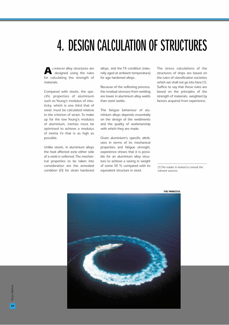
THE PRINCESS
55
Alcan
Mari
ne
1.PROPERTIESOF ALUMINIUM
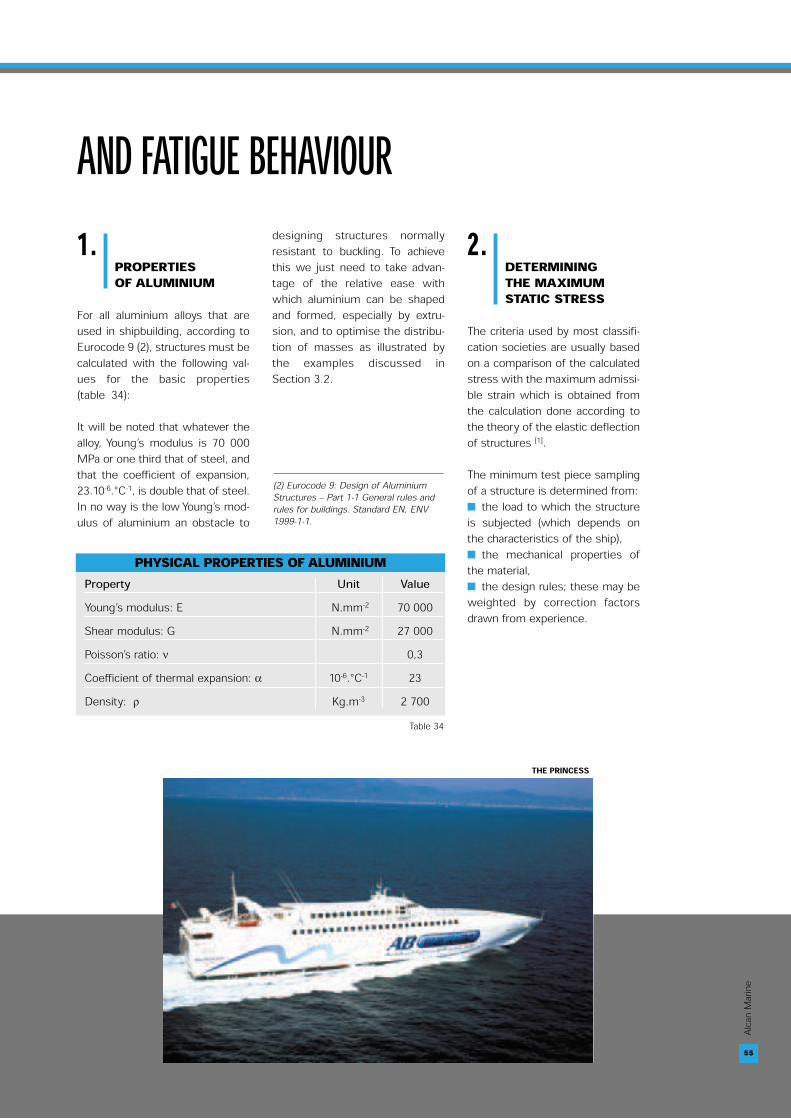
For all aluminium alloys that areused in shipbuilding, according toEurocode 9 (2), structures must becalculated with the following val-ues for the basic properties(table 34):
It will be noted that whatever thealloy, Young’s modulus is 70 000MPa or one third that of steel, andthat the coefficient of expansion,23.10-6.°C-1, is double that of steel.In no way is the low Young’s mod-ulus of aluminium an obstacle to
designing structures normallyresistant to buckling. To achievethis we just need to take advan-tage of the relative ease withwhich aluminium can be shapedand formed, especially by extru-sion, and to optimise the distribu-tion of masses as illustrated bythe examples discussed inSection 3.2.
2.DETERMININGTHE MAXIMUMSTATIC STRESS
The criteria used by most classifi-cation societies are usually basedon a comparison of the calculatedstress with the maximum admissi-ble strain which is obtained fromthe calculation done according tothe theory of the elastic deflectionof structures [1].
The minimum test piece samplingof a structure is determined from: ■ the load to which the structureis subjected (which depends onthe characteristics of the ship),■ the mechanical properties ofthe material,■ the design rules; these may beweighted by correction factorsdrawn from experience.
AND FATIGUE BEHAVIOUR
55
PHYSICAL PROPERTIES OF ALUMINIUMProperty Unit ValueYoung’s modulus: E N.mm-2 70 000 Shear modulus: G N.mm-2 27 000 Poisson’s ratio: ν 0,3Coefficient of thermal expansion: α 10-6.°C-1 23Density: ρ Kg.m-3 2 700
Table 34
(2) Eurocode 9: Design of AluminiumStructures – Part 1-1 General rules andrules for buildings. Standard EN, ENV1999-1-1.
THE PRINCESS
56
Alcan
Mari
ne
2.1The case of a planesection reinforcedwith stiffeners
The criteria used by most classifi-cation societies are usually basedon a comparison of the calculatedstress with the maximum admissi-ble strain which is obtained fromthe calculation done according tothe theory of the elastic deflectionof structures [2].
[1]
where:- σmax = maximum admissible
stress,- p = hydrostatic pressure,- k a correction coefficient,- b = width of the panel,- t = thickness.
In equation [1], thickness t of thesheet of the section is written:
[2]
Compared with the yield strengthRp0,2 of the metal, the aboveexpression is expressed simply:
[3]
According to the DNV rules (3),thickness t can be calculated withthe following equation:
[4]
where:- σ = maximum admissible speci-
fic stress due to lateral pressure - p = hydrostatic pressure,- C = correction coefficient de-
pendent on the geometry,- s = space between stiffeners,- t = thickness.
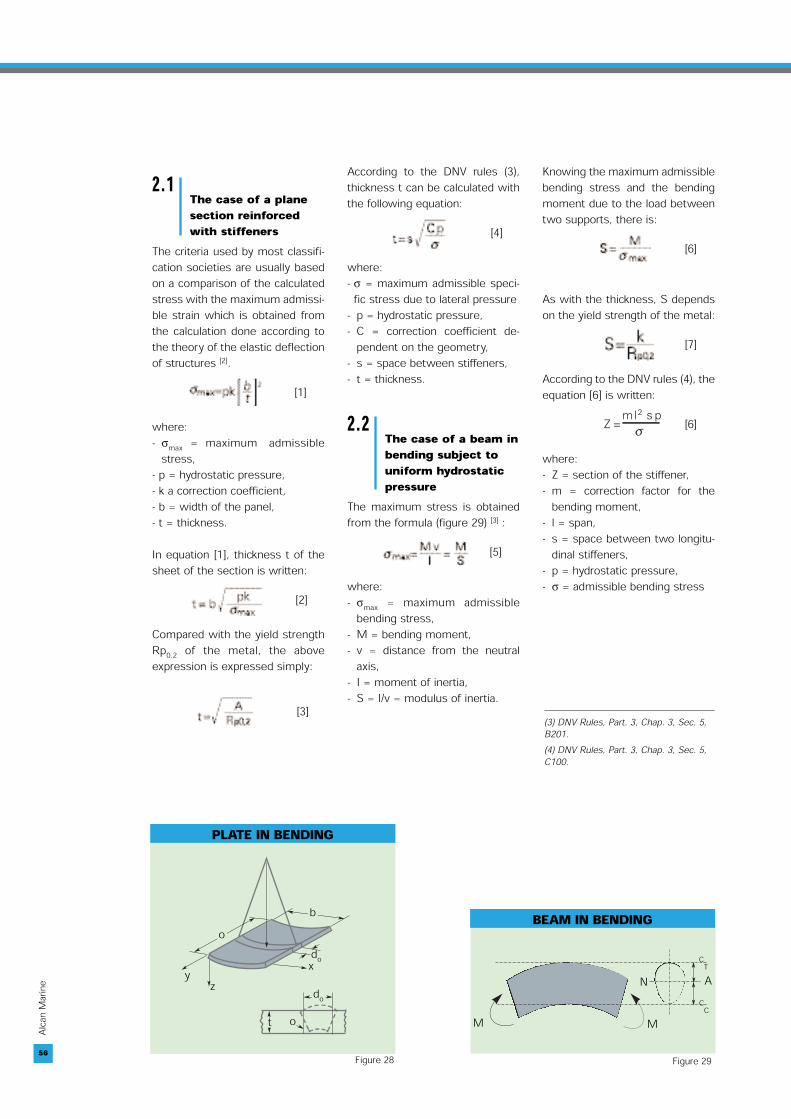
2.2The case of a beam inbending subject touniform hydrostaticpressure
The maximum stress is obtainedfrom the formula (figure 29) [3] :
[5]
where:- σmax = maximum admissible
bending stress,- M = bending moment,- v = distance from the neutral
axis,- I = moment of inertia,- S = I/v = modulus of inertia.
Knowing the maximum admissiblebending stress and the bendingmoment due to the load betweentwo supports, there is:
[6]
As with the thickness, S dependson the yield strength of the metal:
[7]
According to the DNV rules (4), theequation [6] is written:
[6]
where:- Z = section of the stiffener,- m = correction factor for the
bending moment,- l = span,- s = space between two longitu-
dinal stiffeners, - p = hydrostatic pressure, - σ = admissible bending stress
56
PLATE IN BENDING
➤
➤
➤
➤
➤
➤
➤
➤
➤
➤
➤
➤
➤
➤
➤
y z
odo
b
x
t odo
Figure 28
BEAM IN BENDING
M M
➤➤
➤➤
ANC
T
CC
Figure 29
(3) DNV Rules, Part. 3, Chap. 3, Sec. 5,B201.(4) DNV Rules, Part. 3, Chap. 3, Sec. 5,C100.
57
Alcan
Mari
ne
4. DESIGN CALCULATION OF STRUCTURES AND FATIGUE BEHAVIOUR
3.TRANSPOSINGFROM STEELTO ALUMINIUM
Two cases must be considered : ■ a plane section with stiffeners,■ a beam in bending.
3.1The case of a planesection
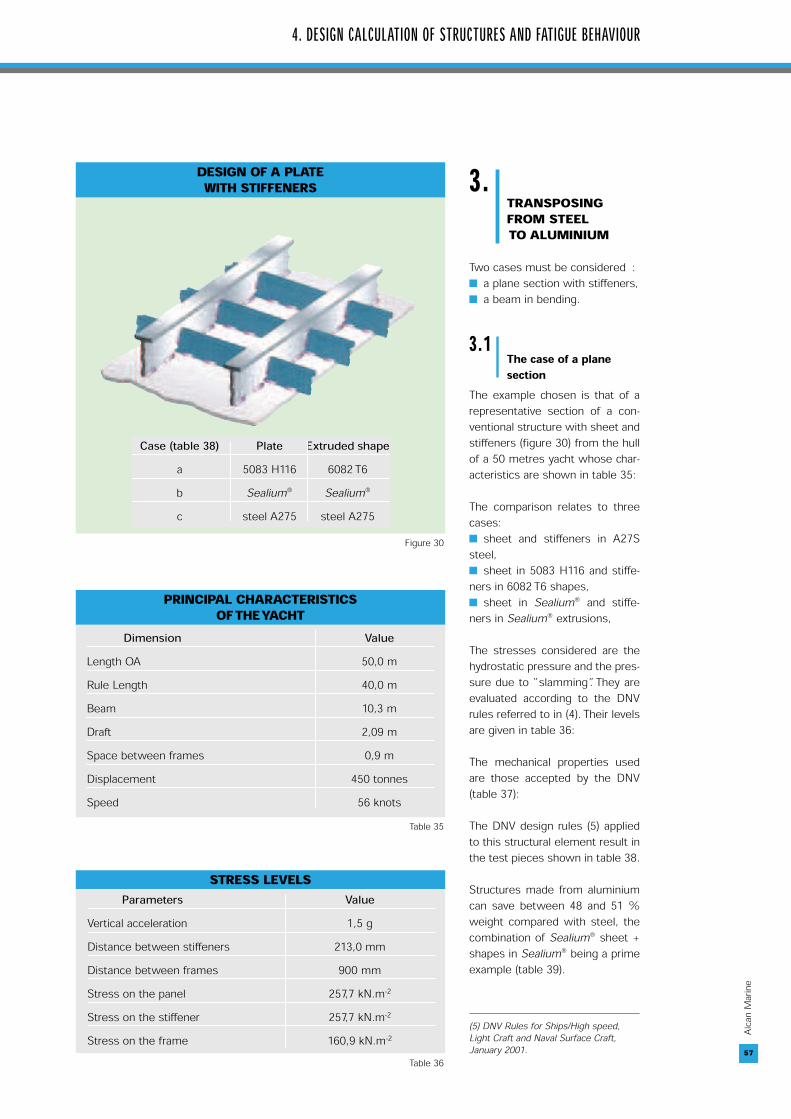
The example chosen is that of arepresentative section of a con-ventional structure with sheet andstiffeners (figure 30) from the hullof a 50 metres yacht whose char-acteristics are shown in table 35:
The comparison relates to threecases:■ sheet and stiffeners in A27Ssteel,■ sheet in 5083 H116 and stiffe-ners in 6082 T6 shapes,■ sheet in Sealium® and stiffe-ners in Sealium® extrusions,
The stresses considered are thehydrostatic pressure and the pres-sure due to “slamming”. They areevaluated according to the DNVrules referred to in (4). Their levelsare given in table 36:
The mechanical properties usedare those accepted by the DNV(table 37):
The DNV design rules (5) appliedto this structural element result inthe test pieces shown in table 38.
Structures made from aluminiumcan save between 48 and 51 %weight compared with steel, thecombination of Sealium® sheet +shapes in Sealium® being a primeexample (table 39).
57
STRESS LEVELSParameters Value
Vertical acceleration 1,5 g Distance between stiffeners 213,0 mm Distance between frames 900 mm Stress on the panel 257,7 kN.m-2
Stress on the stiffener 257,7 kN.m-2
Stress on the frame 160,9 kN.m-2
Table 36
PRINCIPAL CHARACTERISTICS OF THE YACHT
Dimension ValueLength OA 50,0 m Rule Length 40,0 m Beam 10,3 m Draft 2,09 m Space between frames 0,9 m Displacement 450 tonnesSpeed 56 knots
Table 35
Case (table 38) Plate Extruded shapea 5083 H116 6082 T6b Sealium® Sealium®
c steel A275 steel A275
DESIGN OF A PLATE WITH STIFFENERS
Figure 30
(5) DNV Rules for Ships/High speed,Light Craft and Naval Surface Craft,January 2001.

58
Alcan
Mari
ne
3.2The case of a beamin bending
At equal strain, the followingstatement must be verified
hence:
At equal inertia, the transpositionwill be made using extruded alu-minium shapes whose height issome 30 % greater than theheight of steel shapes (fabricated)(figure 31) or fabricated shapes.
As we have already asserted (6),aluminium’s excellent extrudabilitymakes it possible to achieveshapes that are optimised formarine applications: figure 32 andtables 41 and 42, pp. 61-62.58
MECHANICAL PROPERTIES OF MATERIALS Semi Product Alloy Non Welded Metal Welded Metal
Rp0,2 (MPa) Rm (MPa) Rp0,2 (MPa) Rm (MPa) Coefficient f1
Sheet 5083 H116 215 305 125 275 0,60Sealium® 220 305 145 290 0,64
Steel A27S 265 400 Unchanged 1,08 Shapes 6082 T6 260 310 115 205 0,48
Sealium® 190 310 145 290 0,64 (*)Steel A27S 265 400 Unchanged 1,08
(*) The DNV rules puts the 5383 H112 in the same category as Sealium® (5383 H116). Table 37
TEST PIECES OF STRUCTURES Attachment Sheet Thickness (mm) Size of Stiffeners Size of Longitudinals (T-shaped)
5083 H116/6082 T6 7 120 x 6 bulb flats @ 500 x 8 + 60 x 8 mm213 mm spacing
Sealium®/Sealium® 7 105 x 6 bulb flats @ 460 x 8 + 65 x 8 mm220 mm spacing
Steel A27S/Steel A27S 5 100 x 6 bulb flats @ 460 x 4 + 50 x 6 mm240 mm spacing
Table 38
SAVING IN WEIGHT COMPARED WITH STEELStructural Elements Steel 5083 Sheet + Sealium® Sheet +
(kg.m-2) 6082 Shape Sealium® ShapeSheet 39,2 18,9 18,9 Stiffener 36,3 11,9 9,9 Longitudinal 18,7 13,3 12,6 Total 84,40 44,1 41,4 Saving in % 47,8 51,0
Table 39
STEEL AND ALUMINIUM SHAPES
➤
➤
➤ ➤
Fabricated steelshape
Aluminium alloyshape
H 1,3H
Figure 31
59
Alcan
Mari
ne
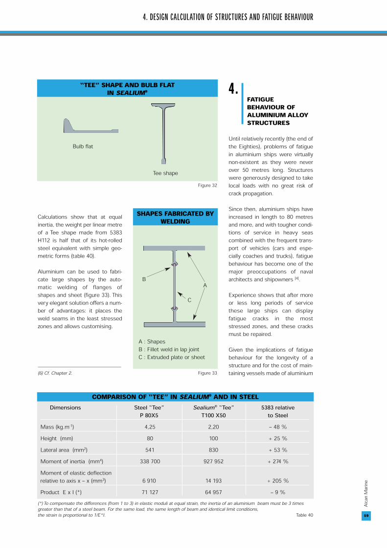
Calculations show that at equalinertia, the weight per linear metreof a Tee shape made from 5383H112 is half that of its hot-rolledsteel equivalent with simple geo-metric forms (table 40).
Aluminium can be used to fabri-cate large shapes by the auto-matic welding of flanges ofshapes and sheet (figure 33). Thisvery elegant solution offers a num-ber of advantages: it places theweld seams in the least stressedzones and allows customising.
4.FATIGUEBEHAVIOUR OFALUMINIUM ALLOYSTRUCTURES
Until relatively recently (the end ofthe Eighties), problems of fatiguein aluminium ships were virtuallynon-existent as they were neverover 50 metres long. Structureswere generously designed to takelocal loads with no great risk ofcrack propagation.
Since then, aluminium ships haveincreased in length to 80 metresand more, and with tougher condi-tions of service in heavy seascombined with the frequent trans-port of vehicles (cars and espe-cially coaches and trucks), fatiguebehaviour has become one of themajor preoccupations of navalarchitects and shipowners [4].
Experience shows that after moreor less long periods of servicethese large ships can displayfatigue cracks in the moststressed zones, and these cracksmust be repaired.
Given the implications of fatiguebehaviour for the longevity of astructure and for the cost of main-taining vessels made of aluminium
4. DESIGN CALCULATION OF STRUCTURES AND FATIGUE BEHAVIOUR
59
COMPARISON OF “TEE” IN SEALIUM® AND IN STEELDimensions Steel “Tee” Sealium® “Tee” 5383 relative
P 80X5 T100 X50 to SteelMass (kg.m-1) 4,25 2,20 – 48 %Height (mm) 80 100 + 25 %Lateral area (mm2) 541 830 + 53 %Moment of inertia (mm4) 338 700 927 952 + 274 %Moment of elastic deflection relative to axis x – x (mm3) 6 910 14 193 + 205 %Product E x I (*) 71 127 64 957 – 9 %
(*) To compensate the differences (from 1 to 3) in elastic moduli at equal strain, the inertia of an aluminium beam must be 3 timesgreater than that of a steel beam. For the same load, the same length of beam and identical limit conditions, the strain is proportional to 1/E*I. Table 40
“TEE” SHAPE AND BULB FLAT IN SEALIUM®
Bulb flat
Tee shapeFigure 32
SHAPES FABRICATED BYWELDING
BA
C
A : ShapesB : Fillet weld in lap jointC : Extruded plate or sheet
(6) Cf. Chapter 2. Figure 33
60
Alcan
Mari
ne
(or steel), this issue must be takeninto account when a ship isdesigned and built [5].
The problem of sensitivity tofatigue is not one specific to alu-minium, but affects steels just asmuch, especially those with a highlimit of elasticity.
5.SERVICECONDITIONS OF HIGH SPEEDSHIPS
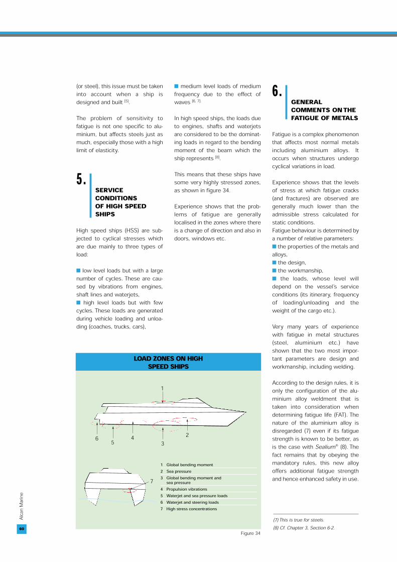
High speed ships (HSS) are sub-jected to cyclical stresses whichare due mainly to three types ofload:
■ low level loads but with a largenumber of cycles. These are cau-sed by vibrations from engines,shaft lines and waterjets,■ high level loads but with fewcycles. These loads are generatedduring vehicle loading and unloa-ding (coaches, trucks, cars),
■ medium level loads of mediumfrequency due to the effect ofwaves [6, 7].
In high speed ships, the loads dueto engines, shafts and waterjetsare considered to be the dominat-ing loads in regard to the bendingmoment of the beam which theship represents [8].
This means that these ships havesome very highly stressed zones,as shown in figure 34.
Experience shows that the prob-lems of fatigue are generallylocalised in the zones where thereis a change of direction and also indoors, windows etc.
6.GENERALCOMMENTS ON THEFATIGUE OF METALS
Fatigue is a complex phenomenonthat affects most normal metalsincluding aluminium alloys. Itoccurs when structures undergocyclical variations in load.
Experience shows that the levelsof stress at which fatigue cracks(and fractures) are observed aregenerally much lower than theadmissible stress calculated forstatic conditions.Fatigue behaviour is determined bya number of relative parameters:■ the properties of the metals andalloys,■ the design,■ the workmanship,■ the loads, whose level willdepend on the vessel’s serviceconditions (its itinerary, frequencyof loading/unloading and theweight of the cargo etc.).
Very many years of experiencewith fatigue in metal structures(steel, aluminium etc.) haveshown that the two most impor-tant parameters are design andworkmanship, including welding.
According to the design rules, it isonly the configuration of the alu-minium alloy weldment that istaken into consideration whendetermining fatigue life (FAT). Thenature of the aluminium alloy isdisregarded (7) even if its fatiguestrength is known to be better, asis the case with Sealium® (8). Thefact remains that by obeying themandatory rules, this new alloyoffers additional fatigue strengthand hence enhanced safety in use.
60
LOAD ZONES ON HIGH SPEED SHIPS
➤
➤
➤
➤
➤
➤
➤
1
6 5 4 32
7
1 Global bending moment2 Sea pressure3 Global bending moment and
sea pressure4 Propulsion vibrations5 Waterjet and sea pressure loads6 Waterjet and steering loads7 High stress concentrations
Figure 34
(7) This is true for steels.(8) Cf. Chapter 3, Section 6-2.

61
Alcan
Mari
ne
4. DESIGN CALCULATION OF STRUCTURES AND FATIGUE BEHAVIOUR
7.SPECIFICS OF THEFATIGUEBEHAVIOUR OFALUMINIUM
Aluminium alloys differ from steelin a number of aspects. Theseinclude:
7.1Fatigue limit
On a smooth test piece, alu-minium has a linear decreasingS/N curve (figure 35). This meansthat the structural calculationsmust be verified for the level ofstress below which there will beno crack propagation for a givenperiod of time which is usuallyfixed at 2.106 cycles [9].
At this level, the fatigue limitdetermined on a “smooth” speci-men of parent metal is 420 MPafor steel and 140 MPa for alu-minium. In welded attachments,the ratio of admissible stresses(FAT) according to the calculationrules between steel and alu-minium alloys is in fact closer to 2(9) on a case by case basis.
7.2The heat affectedzone (HAZ)
Owing to the heat generated bywelding, the mechanical proper-ties of the HAZ are those of theannealed condition (O) for strainhardened alloys and of thequenched condition (T4) for agehardened alloys (figure 35), (10).
Welding has the opposite effecton steels, hardening the heataffected zone because of the rapidcooling (quench effect).
But as with steels, welding alsolowers the threshold of admissi-ble stresses under variableloads. These thresholds (FATs)are laid down by standards, cal-culation rules and classificationsocieties (11).
7.3Residual stresses
These stresses are lower in alu-minium alloys than in steelbecause the heat affected zone issoftened by the heat generated bywelding.
61
➤
➤
➤ ➤
σ
σ
N N
Steel Aluminium104 105 106 107 108 109103 104 105 106 107 108
TYPICAL WÖHLER CURVES
Figure 35
(9) For example, for a 100% tested buttweld, (case 211 of the IWW), the steelFAT is 125 MPa and the aluminium alloyFAT is 50 MPa, or 40 % of the FAT ofsteel.(10) In casting alloys, the fatiguestrength of the welded joint is the sameas the casting. (11) FATs and the way in which they aredetermined may vary somewhat fromone code or one regulation to another.
BULB FLATS IN SEALIUM® (*)Type H Tw H1 Tw1 Bf R S Weight C I Sxx High Sxx Low
(mm) (mm) (mm) (mm) (mm) (mm) (mm2) kg.m-1 (mm) (mm4) (mm3) (mm3)P50 50 3 9 4,5 10 4 218 0,58 21,25 57 085 2 687 1 985P60 60 3,3 9,6 4,8 12 4 284 0,76 24,86 107 947 4 342 3 072P70 70 3,5 10 5 14,5 4 360 0,96 27,95 186 636 6 677 4 439P80 80 3,7 10,4 8,2 16,6 4 436 1,16 31,34 296 312 9 455 6 089P90 100 4,2 11,4 5,7 21 4 620 1,65 38,30 659 291 17 215 10 685P100 120 4,6 12,2 6,1 26 4 833 2,21 44,47 1 271 697 28 600 16 836P140 140 5,1 13,2 6,6 30,5 4,8 1 106 2,94 50,31 2 267 810 45 078 25 285P170 170 5,8 14,6 7,3 37,5 5,8 1 580 4,20 58,99 4 717 199 79 966 42 493
(*) Cf figure 32. Table 41
62
Alcan
Mari
ne
7.4Fracture mode
These stresses are lower in alu-minium alloys than in steelbecause the heat affected zone issoftened by the heat generated bywelding.
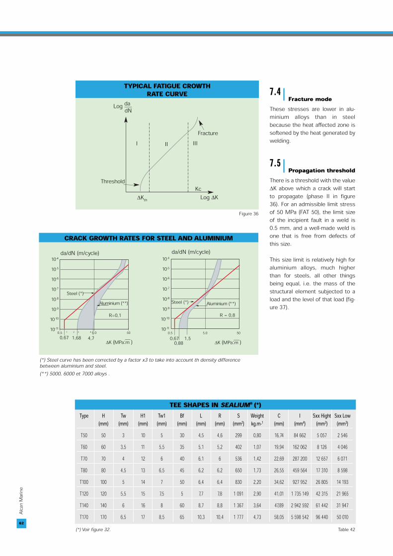
7.5Propagation threshold
There is a threshold with the value∆K above which a crack will startto propagate (phase II in figure36). For an admissible limit stressof 50 MPa (FAT 50), the limit sizeof the incipient fault in a weld is0.5 mm, and a well-made weld isone that is free from defects ofthis size.
This size limit is relatively high foraluminium alloys, much higherthan for steels, all other thingsbeing equal, i.e. the mass of thestructural element subjected to aload and the level of that load (fig-ure 37).
62
R = 0,8
CRACK GROWTH RATES FOR STEEL AND ALUMINIUM
10-4
10-5
10-6
10-7
10-8
10-9
10-10
10-11
10-4
10-5
10-6
10-7
10-8
10-9
10-10
10-110,5 1 2 3 4 5.0 50
∆K (MPa:m )0,5 5,0 50
∆K (MPa:m )
da/dN (m/cycle) da/dN (m/cycle)
Steel (*)Aluminium (**)
R=0,1
0,67 1,68 4,7
Aluminium (**)Steel (*)
0,88 1,5
➤➤
➤
➤
0,67
(*) Steel curve has been corrected by a factor x3 to take into account th density differencebetween aluminium and steel.(**) 5000, 6000 et 7000 alloys .
Log dadN
Fracture
Threshold
I II III
KcLog ∆K∆Kth
TYPICAL FATIGUE CROWTH RATE CURVE
Figure 36
Type H Tw H1 Tw1 Bf L R S Weight C I Sxx Hight Sxx Low(mm) (mm) (mm) (mm) (mm) (mm) (mm) (mm2) kg.m-1 (mm) (mm4) (mm3) (mm3)
T50 50 3 10 5 30 4,5 4,6 299 0,80 16,74 84 662 5 057 2 546T60 60 3,5 11 5,5 35 5,1 5,2 402 1,07 19,94 162 062 8 126 4 046T70 70 4 12 6 40 6,1 6 536 1,42 22,69 287 200 12 657 6 071T80 80 4,5 13 6,5 45 6,2 6,2 650 1,73 26,55 459 564 17 310 8 598T100 100 5 14 7 50 6,4 6,4 830 2,20 34,62 927 952 26 805 14 193T120 120 5,5 15 7,5 5 7,7 7,8 1 091 2,90 41,01 1 735 149 42 315 21 965T140 140 6 16 8 60 8,7 8,8 1 367 3,64 47,89 2 942 592 61 442 31 947T170 170 6,5 17 8,5 65 10,3 10,4 1 777 4,73 58,05 5 598 542 96 440 50 010
TEE SHAPES IN SEALIUM® (*)
(*) Voir figure 32. Table 42
63
Alcan
Mari
ne
4. DESIGN CALCULATION OF STRUCTURES AND FATIGUE BEHAVIOUR
63
8.CLASSIFICATION OF ALUMINIUMALLOYS
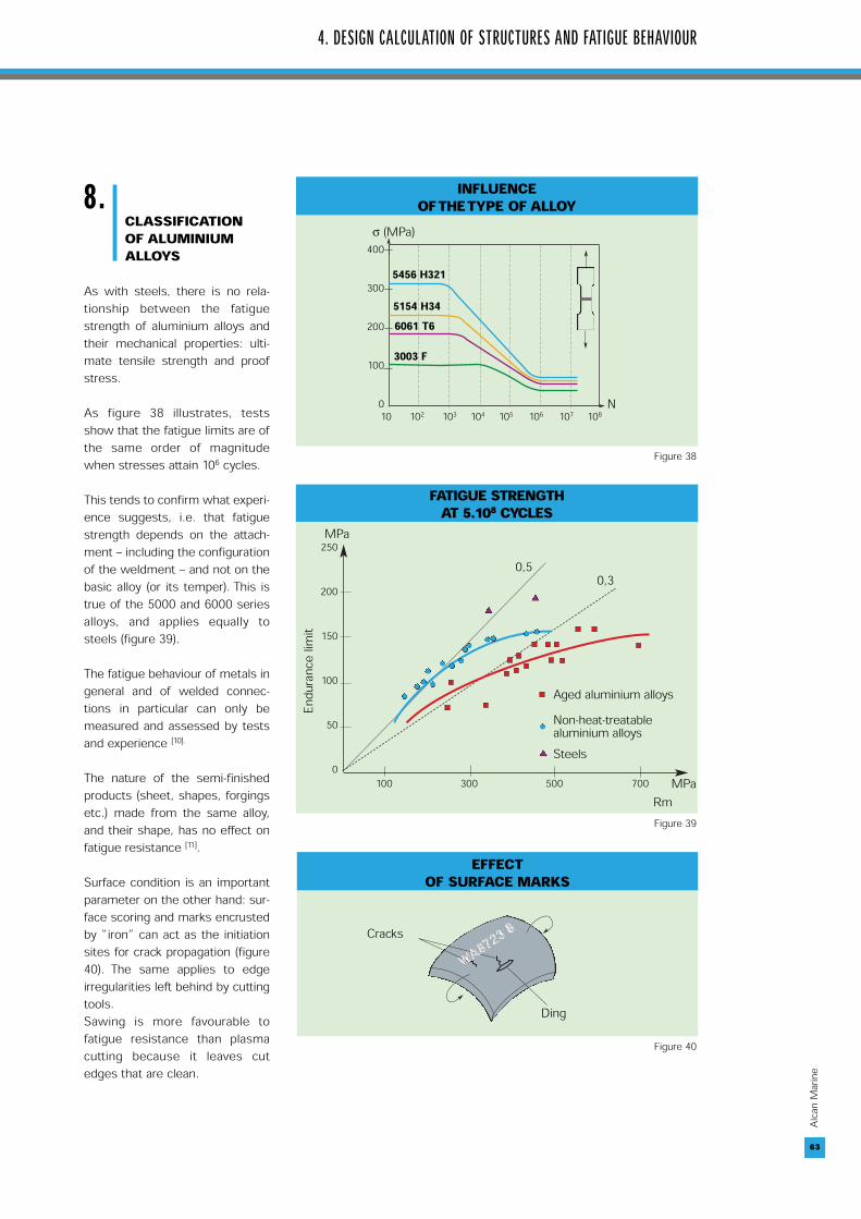
As with steels, there is no rela-tionship between the fatiguestrength of aluminium alloys andtheir mechanical properties: ulti-mate tensile strength and proofstress.
As figure 38 illustrates, testsshow that the fatigue limits are ofthe same order of magnitudewhen stresses attain 106 cycles.
This tends to confirm what experi-ence suggests, i.e. that fatiguestrength depends on the attach-ment – including the configurationof the weldment – and not on thebasic alloy (or its temper). This istrue of the 5000 and 6000 seriesalloys, and applies equally tosteels (figure 39).
The fatigue behaviour of metals ingeneral and of welded connec-tions in particular can only bemeasured and assessed by testsand experience [10].
The nature of the semi-finishedproducts (sheet, shapes, forgingsetc.) made from the same alloy,and their shape, has no effect onfatigue resistance [11].
Surface condition is an importantparameter on the other hand: sur-face scoring and marks encrustedby “iron” can act as the initiationsites for crack propagation (figure40). The same applies to edgeirregularities left behind by cuttingtools.Sawing is more favourable tofatigue resistance than plasmacutting because it leaves cutedges that are clean.
INFLUENCEOF THE TYPE OF ALLOY
5456 H321
5154 H346061 T6
3003 F
400
300
200
100
010 102 103 104 105 106 107 108
➤
➤
σ (MPa)
N➤
➤
FATIGUE STRENGTH AT 5.108 CYCLES
MPa250
200
150
100
50
0100 300 500 700 MPa
Endu
rance
limit
Rm
0,50,3
Aged aluminium alloysNon-heat-treatablealuminium alloysSteels
EFFECTOF SURFACE MARKS
➤
➤
Cracks
Ding
Figure 38
Figure 39
Figure 40
64
Alcan
Mari
ne
64
9.FATIGUE LIFE OFWELDMENTS
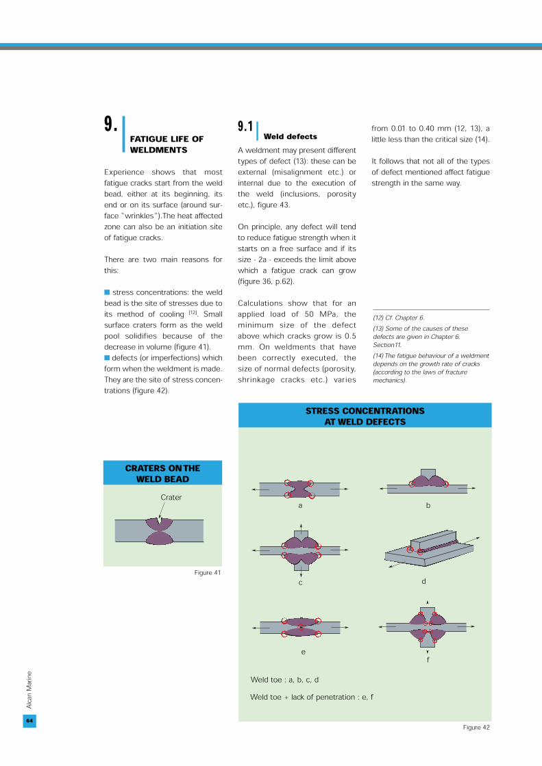
Experience shows that mostfatigue cracks start from the weldbead, either at its beginning, itsend or on its surface (around sur-face “wrinkles”).The heat affectedzone can also be an initiation siteof fatigue cracks.
There are two main reasons forthis:
■ stress concentrations: the weldbead is the site of stresses due toits method of cooling [12]. Smallsurface craters form as the weldpool solidifies because of thedecrease in volume (figure 41).■ defects (or imperfections) whichform when the weldment is made.They are the site of stress concen-trations (figure 42).
9.1Weld defects
A weldment may present differenttypes of defect (13): these can beexternal (misalignment etc.) orinternal due to the execution ofthe weld (inclusions, porosityetc.), figure 43.
On principle, any defect will tendto reduce fatigue strength when itstarts on a free surface and if itssize - 2a - exceeds the limit abovewhich a fatigue crack can grow(figure 36, p.62).
Calculations show that for anapplied load of 50 MPa, theminimum size of the defectabove which cracks grow is 0.5mm. On weldments that havebeen correctly executed, thesize of normal defects (porosity,shrinkage cracks etc.) varies
from 0.01 to 0.40 mm (12, 13), alittle less than the critical size (14).
It follows that not all of the typesof defect mentioned affect fatiguestrength in the same way.
CRATERS ON THE WELD BEAD
Crater
➤
STRESS CONCENTRATIONS AT WELD DEFECTS
➤
➤
a➤
➤
b
➤
➤
➤
➤
c
➤
➤
➤
➤
f
➤
➤
e
➤
➤
d
Weld toe : a, b, c, dWeld toe + lack of penetration : e, f
Figure 42
Figure 41
(12) Cf. Chapter 6.(13) Some of the causes of thesedefects are given in Chapter 6,Section11.(14) The fatigue behaviour of a weldmentdepends on the growth rate of cracks(according to the laws of fracturemechanics).
65
Alcan
Mari
ne
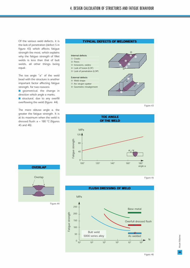
Of the various weld defects, it isthe lack of penetration (defect 5 infigure 43) which affects fatiguestrength the most, which explainswhy the fatigue strength of filletwelds is less than that of buttwelds, all other things beingequal.
The toe angle “a” of the weldbead with the structure is anotherimportant factor affecting fatiguestrength, for two reasons: ■ geometrical, the change indirection which angle a marks, ■ structural, due to any overfilloverflowing the weld (figure 44).
The more obtuse angle a, thegreater the fatigue strength. It isat its maximum when the weld isdressed flush: a = 180 °C (figures45 and 46).
4. DESIGN CALCULATION OF STRUCTURES AND FATIGUE BEHAVIOUR
65
Internal defects① Cracks② Pores③ Inclusions, oxides④ Lack of fusion (LOF)⑤ Lack of penetration (LOP)
External defects⑥ Weld shape⑦ Arc strujen spatter⑧ Geometric misalignment
❸ ❹
❺
⑥
❶
⑧
❷
❶
❼
❼
❺
TYPICAL DEFECTS OF WELDMENTS
OVERLAP
➤ ➤
Overlap
120
80
40
0100° 120° 140° 160° 180°
angle α
MPa
➤➤α
Fatig
uestr
ength
TOE ANGLE OF THE WELD
250
200
150
100
50
0 103 104 105 106 107 108N
Butt weld 5000 series alloy
Base metal
Overfull dressed flush
As welded
MPa
Fatig
uestr
ength
FLUSH DRESSING OF WELD
Figure 44
Figure 46
Figure 45
Figure 43

66
Alcan
Mari
ne
9.2Classification of weldments
The limits of endurance (FAT) thatare given in codes and regulationshave been established on thebasis of standard tests conductedon specimens taken from attach-ments and feedback on structuresin service [14].
Eurocode 9 proposes limits ofendurance (FAT 25 to 62 MPa) as afunction of the size of the defects(figure 47) (misalignment, under-cut, lack of root penetration,porosity, crack etc.) and the extentof controls corresponding to thedesired level of FAT.
The influence of the size of fourdefects on the limits of endurance(FAT) is given in table 43 by way ofexample
Design codes and regulations con-fine themselves solely to the con-figuration of the weld to define theacceptable limit of endurance(FAT), as figures 48 to 50 illustrate.
66
FATIGUE STRENGTH (FAT) ACCORDING TO EUROCODE 9
➤
➤
➤
➤
➤
➤
➤➤
➤
➤
➤
➤
➤➤h
z
zaaθ
θ
➤
➤➤
➤
➤
➤
➤
➤
➤
➤
➤
➤
➤
➤
➤ ➤
θθh
θ
h
h
ts
a) a and z are minimum distances
b)
c)
➤
➤
t➤
➤
t ➤
➤
➤
➤
th
h
s➤
➤
➤
➤
➤
➤
s
➤➤
t ➤ ➤
➤
➤
t
➤
➤➤
➤
➤➤
➤
➤
Length of attachmenth1
h2
h1
h
LhL
d)
➤
➤
Figure 47
➤
➤
➤
➤
➤
➤
➤
➤
➤
➤
➤ ➤
LIMIT OF ENDURANCE OF BUTT WELDS (according to IIW Recommendations, Group XIII – XV, 1996)
Case 211 : Transverse loaded butt weld (X-groove or V-groove) ground flush toplate, 100% NDT (*)
Case 212 : Transverse butt weld made in shop in flat position, toeangle ≤ 30°, NDT
Case 213 : Transverse butt weld, toe angle ≤ 50°
Case 215 : Transverse butt weld, toe angle ≤ 50°, or transverse butt weld onpermanent backing bar
Case 223 : Transverse butt weld, NDT, with transition on thickness and widthSlope 1:5Slope 1:3Slope 1:2
(*) Non destructive test. Figure 48

67
Alcan
Mari
ne
4. DESIGN CALCULATION OF STRUCTURES AND FATIGUE BEHAVIOUR
➤
➤
➤➤
Case 313 : Longitudinal butt weld, without stop/start positions, NDT . . . . . . . . . . . . . . . . . . . . . . . .45With stop/start position . . . . . . . . . 36
Case 324 : Intermittent longitudinalfillet weld (based on normal stress inflange σ and shear stress in web τ atweld ends).
FATIGUE STRENGTH (FAT) OF LONGITUDINAL WELDS(recommendations of IIW, Group XIII - XV, 1996)
Figure 49
FATIGUE STRENGTH (FAT) OF CRUCIFORM WELDS(recommendations of IIW, Group XIII - XV, 1996)
➤
➤ ➤
➤
➤
et➤
➤ ➤
➤
➤
et
➤
➤
➤ ➤
➤
➤
et
➤
a
➤
➤
➤
➤
Case 411 : Cruciform joint or T-joint, K- butt welds, full penetration, no lamellartearing, misalignment e < 0,15 t, weld toes ground, toe crack
Case 412 : Cruciform joint or T-joint, K- butt welds, full penetration, no lamellartearing, misalignment e < 0,15 t, toe crack
Cas 413 : Cruciform joint or T-joint, fillet welds, or partial penetrating K- buttweld, misalignment e < 0,15 t, toe crack
Cas 414 : Cruciform joint or T-joint, fillet welds, or partial penetrating K- buttwelds (including toe ground welds), weld root crack. Analysis based on stress inweld throat
Figure 50
τ/σ = 0. . . . . . . . . . . . . . . 32τ/σ = 0,0 – 0,2 . . . . . . . . . 28τ/σ = 0,0 – 0,3 . . . . . . . . . 25τ/σ = 0,0 – 0,4 . . . . . . . . . 22τ/σ = 0,0 – 0,5 . . . . . . . . . 20t/σ = 0,0 – 0,6 . . . . . . . . . 18t/σ = 0,0 – 0,7 . . . . . . . . . 16t/σ = > 0,7 . . . . . . . . . . . . 14
ACCEPTANCE LEVEL OF INDUSTRIAL WELDS (*)Defect Weld Weld Figures Size of FAT 25 FAT 31 FAT 39 FAT 49 FAT 62
direction (*) defectWeld angle all types Transv. a, b θ ≥ 120° 150° 165° 175° -
Longit a, b θ ≥ 90° 90° 90° 90° 175°Excessive bead thickness butt Transv. b h ≤ 5 4 2 0,5 -
Longit b h ≤ 6 5 4 3 0,5 Misalignment butt Transv. d h ≤ D + 0,1 t D + 0,05 t D + 0,05 t D + 0,05 t - Lack of root pen-tration butt Transv. c h ≤ - - - - -
Longit c h ≤ D + 0,1 t D + 0,1 t D + 0,05 t D + 0,05 t - D = dimension specified on drawings (*) From table D.2 Eurocode (9). Table 43

68
Alcan
Mari
ne
INFLUENCE OF WELDED STRUCTURES ON FATIGUE BEHAVIOUR [16 , 17]
Correct arrangement which avoidswelds crossing over (which candestroy much of the underlyingweld).
Path of a stiffener over skinsheet.
At left, torch cannot access beneaththe shape and the weld bead cannotbe wrapped, so there is a risk ofcracking.At right, weld is correctly made,beads do not cross over, the sheetof the frame is welded to the flatside of the longitudinal.
Path of a longitudinal through aframe.
The weld bead must be wrappedat the end of the gusset to avoidcrack initiation.
Gusset of floor plate on shipbottom.
RemarksExample of Structure
10.INFLUENCE
OF DESIGN ANDFABRICATIONARRANGEMENTS
The fatigue behaviour of alu-minium alloy ships depends ■ on the design arrangementsdefined by the design consultancy■ on the execution of welds in theshipyard.
10.1Design of weldedattachments
This is a very important parameter:Design engineers must proposestructures in which the stress con-centrations are as low as possible,
while keeping within acceptablecost limits. The “hot spot” methodcan be used to identify the sensi-tive zones [15].
The influence of the designarrangements of some typicalwelded structures is given intable 44.
10.2Design of bolted and bondedattachments
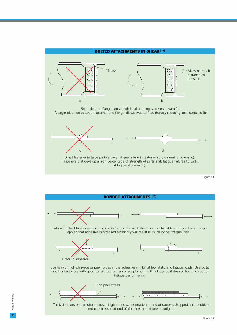
Bolted and bonded joints must bedesigned to offer good fatiguebehaviour (Figures 51 and 52, p.70). It is particularly important toensure that the diameter of thebolts is proportional to the dimen-sions of the attachment.
10.3Making weldments
Experience shows that the fatiguebehaviour of welded aluminiumalloy structures is more sensitiveto weld defects than welded steelstructures [].
This is why shipbuilding in particu-lar, and aluminium fabrication ingeneral, requires:■ better welding skills than areneeded for steel fabrication, ■ tighter control of weldments, atleast those located in zones moststressed by fluctuations of load.

69
Alcan
Mari
ne
Cracks
➤
Cracks
➤
➤ ➤
➤ ➤
4. DESIGN CALCULATION OF STRUCTURES AND FATIGUE BEHAVIOUR
At left, the recess in the shapecauses a stress concentration that is avoided by the arrangement on the right.
Connection of a longitudinal and a bar to the sheet of the skin.
The change of direction createsbending and torsional stresses.These stresses are avoided by adding a plate to form a box.
Connection of two shapes.
At left, the stiffener stops in themiddle of the sheet causingstresses, with the risk of tearingby bending.At right, the scallop in the reinfor-cement avoids welds crossingand distributes bending forces.
Stiffeners on sheet.
At left, with a shape on each sideof the bulkhead, alignment will bepoor and stresses will occur.At right, the shape passesthrough the bulkhead which is ‘hung’ on the shape.
Bulkhead crossing.
Enough space must be left for the torch to enter everywhere and wrap around the transversebar on the longitudinal.
Connection of two shapes, e.g. longitudinal and bar.
Assembly too tight, torch cannotreach the inside faces of thelongitudinal reinforcements.
Deck flooring, junction of bar and reinforcement.
RemarksExample of Structure
Table 44
➤
➤
➤
➤
➤
➤
➤
➤ ➤
Cracks
➤
➤
➤
➤
70
Alcan
Mari
ne
BOLTED ATTACHMENTS IN SHEAR [13]
➤
➤
➤
➤
➤
➤
Crack Allow as muchdistance as possible
Bolts close to flange cause high local bending stresses in web (a).A larger distance between fastener and flange allows web to flex, thereby reducing local stresses (b)
a b
➤
➤ ➤
➤
c dSmall fastener in large parts allows fatigue failure in fastener at low nominal stress (c).
Fasteners that develop a high percentage of strength of parts shift fatigue failures to parts at higher stresses (d).
BONDED ATTACHMENTS [13]
➤
➤ ➤
➤
➤
➤ ➤
➤
Joints with short laps in which adhesive is stressed in inelastic range will fail at low fatigue lives. Longerlaps so that adhesive is stressed elastically will result in much longer fatigue lives.
➤
➤
➤
➤ ➤
➤
➤
Crack in adhesiveJoints with high cleavage or peel forces in the adhesive will fail at low static and fatigue loads. Use boltsor other fasteners with good tensile performance; supplement with adhesives if desired for much better
fatigue performance.
➤➤
➤
➤
➤
➤
➤
High peel stress
Thick doublers on thin sheet causes high stress concentration at end of doubler. Stepped, thin doublersreduce stresses at end of doublers and improves fatigue.
Figure 51
Figure 52

71
Alcan
Mari
ne
4. DESIGN CALCULATION OF STRUCTURES AND FATIGUE BEHAVIOUR
11.REFERENCESTANDARDS ANDREGULATIONS
Eurocode 9: Design of AluminiumStructures – Part 1 – 1 Generalrules and rules for buildings.Standard EN, ENV 1999-1-1, May1998Eurocode 9: Design of AluminiumStructures – Part 2: Structuressusceptible to fatigue, StandardEN, ENV 1999-2, May 1998Recommandations pour le calculen fatigue de structures enalliages d’aluminium, ECCS, 1992,Institut de la SoudureAluminum Structures. A guide totheir specifications and design. J.Randolph Kissell, Robert L. Ferry.John Wiley & Sons, Inc., 2002British Standard BS 8118.Structural use of aluminium. Part1. Code of practice for design,1991British Standard BS 8118.Structural use of aluminium. Part2. Specifications for materials,workmanship and protectionBureau Veritas – Rules for the clas-sification of High Speed Craft;February 2002ABS – Requirements for materialsand welding, Part 2 Aluminum,Fiber Reinforced Plastics (FRP),1997DNV – Rules for classification ofhigh speed, light craft and navalsurface craft. Structures, equip-ment, Part 3, Chapter 3; Hull struc-ture design, aluminium alloy, July2002DNV – Rules for classification ofhigh speed, light craft and navalsurface craft. Structures, equip-ment, Part 3, Chapter 3; Hull struc-ture design, aluminium alloy, July2002DNV - Rules for classification ofships / high speed, light craft andnaval surface craft. New Building,materials and welding, Part 2,Chapter 2, Metallic materials,January 2001DNV - Rules for classification ofships. New Building, materials andwelding, Part 2, Chapter 3,Welding, January 1996
Fatigue design aluminium compo-nents structures. M.E. Sharp, G.E. Nordwark, C. C. MenzerMcGraw-Hill Fatigue of aluminium structuralweldments. Ship StructureCommittee 2000. Rapport SSC-410, NTIS #PB2000-108442TALAT, Chapter F2204. La concep-tion, compiled by SteinnarLundberg, Hydro AluminiumStructures, Karmoy, 30 pagesTALAT, Chapter F2205.Conceptions particulières, com-piled by Torsten Hoglund, RoyalInstitute of Technology, Stockholmand Dimitris Kosteas, TechnischeUniversität München, 27 pagesTALAT, Lecture 2301. Design ofMembers : Examples, preparedTorsten Hoglund, Royal Institut ofTechnology, Stocklom, 1999, 125pagesTALAT, EAA, Lecture 2401: FatigueBehaviour and Analysis, preparedby Dimitris Kosteas, TechnischeUniversität München, 1994, 81pagesTALAT, EAA, Lecture 2402: DesignRecommandations for FatigueLoaded Structures, prepared byDimitris Kosteas, TechnischeUniversität München, 1994TALAT, EAA, Lecture 2403:Applied Fracture Mechanics, pre-pared by Dimitris Kosteas,Technische Universität München,1994, 49 pagesTALAT, EAA, Lecture 2405.Fatigue and Fracture in aluminiumstructures, prepared by DimitrisKosteas, Technische UniversitätMünchen, 1994, 40 pagesTALAT, EAA, Lecture 2406.Fatigue and Fracture in AluminiumStructures, prepared by DimitrisKosteas, Technische UniversitätMünchen, 1999, 5 pagesTALAT, EAA, Lecture 2406, Annex1. Fatigue and Fracture inAluminium Structures, preparedby Dimitris Kosteas, TechnischeUniversität München, 1994, 6pagesTALAT, EAA, Lecture 2406, Annex2. Fatigue and Fracture in alu-minium structures, prepared byDimitris Kosteas, TechnischeUniversität München, 1999,6 pages
Bibliography[1] “Reexamination of design criteria forstiffened plate panels”, GHOSE D. ANDNAPPI N, SCC382, June 1994, ShipStructure Committee.[2] “Ship Structural design”, HUGUES, 1988,SNAME.[3] “Engineering Mechanics of solids”,E. P POPOV, Prentice Hall, 1990. [4] “Fatigue resistance poses designchallenge”, R. WHITE, Speed at Sea,August 1998, pp. 45-46. [5] “Fatigue design assessment ofaluminium fast craft”, T. HALL, F. VIOLETTE,H. CHUNG, The third AusmarineConference, April 1998, pp. 125-136.[6] “High strength alloys and the fatiguelife of HSLC”, H. CRAIG, J. DONAVAN,A. FREDRIKSEN, 14th Fast FerryInternational Conference, Copenhagen,February 1998. [7] “Fatigue analysis of high speedaluminium catamarans”, S. E. HEGGELUND,B. W. TVEITEN, T. MOAN, The thirdInternational Forum on Aluminium Ships,Haugesund, Norway, May 1998.[8] “Fatigue assessment of weldedaluminum ships details”, B. W. TVEITEN,T. MOAN, 5th International conference onfast transportation, Seattle, August 1999.[9] “Fatigue of marine grade aluminiumalloys” R. C. CALCRAFT, G. O. SCHUMANN,D. M. VIANO, Australian Welding Journal,Vol 42, 1997, pp. 22-25.[10] « Fatigue crack propagation inaluminium”, R. JACCARD, IIW, DocumentXIII-1377-90.[11]”Significance of mechanical propertiesin design and applications”, Aluminum,design and applications, Vol II, chap 4,edited by Kent R. Van Horn, ASM, 1967. [12] Reference Jaccard IIW, DocumentXIII-1377-90.[13] “Fatigue design of aluminium alloysstructures”, S. J. MADDOX, Proceedings ofthe Second International Conference onAluminium Weldments, Düsseldorf FRG1982.[14] “Calcul en fatigue des joints soudés”,M. BRAMAT, Mécanosoudage etconception, CETIM publication. [15] “Fatigue assessment of aluminiumwelded components”, M. BOUET GRIFFON,M. COURBIÈRES, JC. EHRSTRÖM, PechineyCRV, 1999.[16] “Fatigue damage in aluminium shipsand the betterment of details”, KAZUYOSHIMATSUOKA, HOROSHI ISHIWATAT, MANTROHIRAYAMA, YUZURU FUJITA. The ThirdInternational Forum on Aluminium Ships,Haugesund, Norway, May 1998.[17] “Fatigue design aluminiumcomponents structures”, M.E. SHARP,G. E. NORDWARK, C. MENZER MCGRAW-HILL.[18] “Fatigue of aluminium structuralweldments”, Ship Structure Committee2000. Report SSC-410, NTIS #PB2000-108442.

72
Alcan
Mari
ne
STRUCTURE OF MONOHULL


![Analysis of Tooth Interior Fatigue Fracture Using Boundary … · 2020-03-31 · Tooth Interior Fatigue Fracture Calculation Methods MackAldener [1-3] has shown that an analysis method](https://static.fdocuments.net/doc/165x107/5f263f07055e6d2cab506357/analysis-of-tooth-interior-fatigue-fracture-using-boundary-2020-03-31-tooth-interior.jpg)