Design Book - GitHub Pages
24
Design Book Haley So 2019
Transcript of Design Book - GitHub Pages

Design BookHaley So 2019

Voila!

Voila!

Ideation (down-selected!)
Possibilities:-use sound sensor and have the amplitude correspond to the brightness of the lights- maybe lights will only turn on when you wave your hand in front of it or push a button
-play music/ding at the hour-alarm clock? How would I set the time to wake up?
-button at top, change from time to weather

Preliminary block diagram

component selection (down-selected!)Component Link Notes/use Priority
100 Neopixel LEDsNeoPixel RGB 5050 LED with Integrated Driver Chip - 100 Pack - chainable (see more on later slide) P1
Atmega328P Arduino kit P0
Sound Sensor Module
Arduino kit Basically a capacitor-- capacitance changes with vibrations- two modes: can read analog (continuous) or read high once sound reaches a certain level (digital) (See later slide) P2
LED Dot Matrix 8x8
Arduino kit Operating Voltage: DC 4.7V – 5.3V, Typical Voltage: 5V, Operating Current: 320mA, Max Operating Current: 2A, Drive with MAX7219 LED driver chip P1
MAX7219 LED driver chip Arduino Kit
P1
Real time clock
Arduino kit
P0
Three buttons
Arduino kit One button selects either hour or min--will flash, and other buttons increase or decreasePress the first button again to ‘enter’ P0
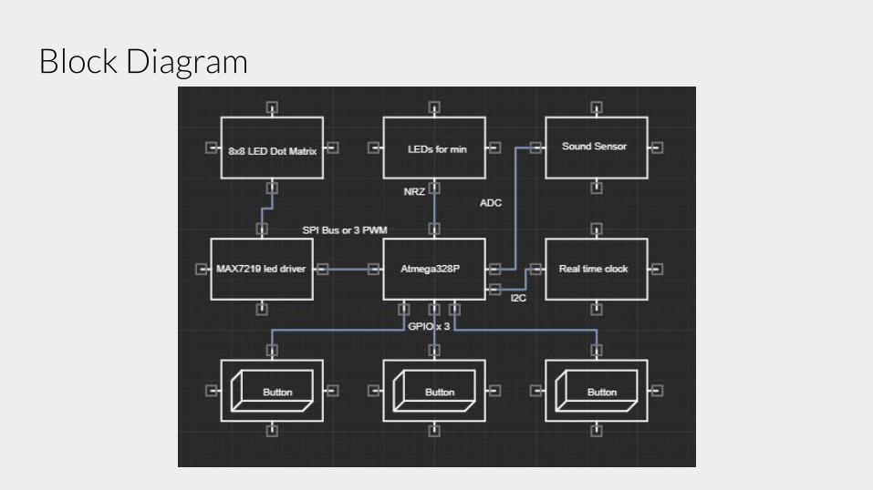
Block Diagram

Pin Allocation Table: https://docs.google.com/spreadsheets/d/1OgjKlriLdlXydB-5rfnWKp9DKhT2HOxpZ84q08SG1-A/edit#gid=0
ATMEGA 328P PDIP
RESET 1 ~RESET PC5 (ADC5/SCL/PCINT13) 28 RTC DS1307 SCLRXD 2 (PCINT16/RXD) PD0 PC4 (ADC4/SDA/PCINT12) 27 RTC DS1307 SDATXD 3 (PCINT17/TXD) PD1 PC3 (ADC3/PCINT11) 26 MAX4466 Audio Sensor
4 (PCINT18/INT0) PD2 PC2 (ADC2/PCINT10) 25Neopixel 1 DIN 5 (PCINT19/OC2B/INT1) PD3 PC1 (ADC1/PCINT9) 24 Sound VMA309 AO
6 (PCINT20/XCK/T0) PD4 PC0 (ADC0/PCINT8) 23 Sound VMA309 DOVCC 7 VCC GND 22 GNDGND 8 GND AREF 21 VCC
Crystal 1 9 (PCINT6/XTAL1/TOSC1) PB6 AVCC 20 VCC
Crystal 1 10 (PCINT7/XTAL2/TOSC2) PB7 PB5 (SCK/PCINT5) 19 single ledButton 1 11 (PCINT21/OC0B/T1) PD5 PB4 (MISO/PCINT4) 18 MISOButton 2 12 (PCINT22/OC0A/AIN0) PD6 PB3 (MOSI/OC2A/PCINT3) 17 MOSIButton 3 13 (PCINT23/AIN1) PD7 PB2 (~SS/OC1B/PCINT2) 16 LED Matrix DINLED CLK 14 (PCINT0/CLKO/ICP1) PB0 PB1 (OC1A/PCINT1) 15 LED Matrix LOAD (~CS)

Part Details

Using the Neopixels
Neopixels:
- Install library for code- Addressing individual pixels
Supply separate 5V to the pixels instead of having the arduino power it. The Arduino can only continuously supply about 500mA to the 5V pin. Each Neopixel can draw up to 60 mA at full brightness.
- Add ~470 ohm resistor between the arduino and the first pixel data input to prevent spikes that can damage the first pixel- With through-hole NeoPixels (5mm), add a .1uF cap between the + and - pins of EACH PIXEL. Individual pixels may misbehave
without this "decoupling cap"- When using a DC Supply, add a large cap (1000uF, 6.3 V or higher) across the + and - terminals. This prevents the onrush of
current from damaging the pixels.- If powering pixels from outside source, power leds before powering microcontroller.
Using the sound sensor
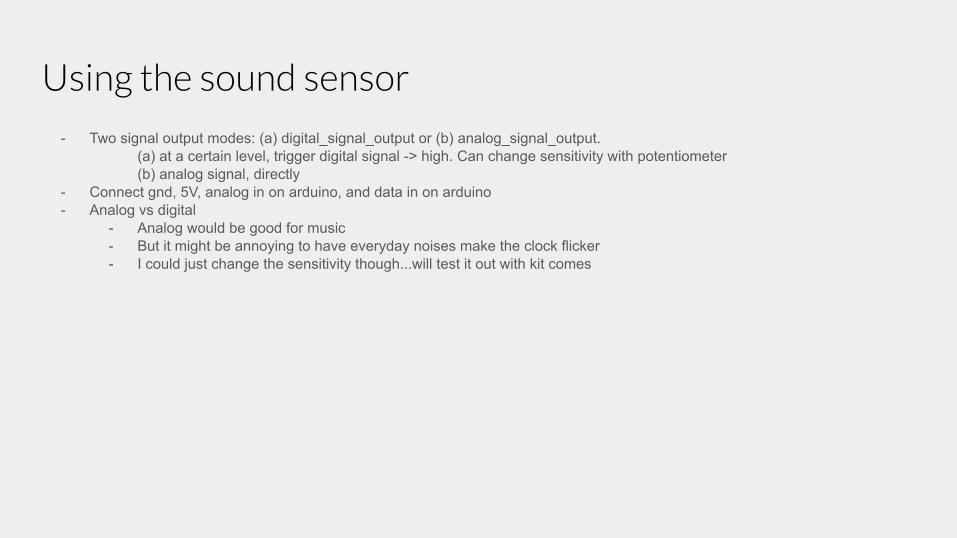
- Two signal output modes: (a) digital_signal_output or (b) analog_signal_output.(a) at a certain level, trigger digital signal -> high. Can change sensitivity with potentiometer(b) analog signal, directly
- Connect gnd, 5V, analog in on arduino, and data in on arduino- Analog vs digital
- Analog would be good for music- But it might be annoying to have everyday noises make the clock flicker- I could just change the sensitivity though...will test it out with kit comes

Using MAX7219 and 8x8 led matrix
- Can control all 64 leds using only 3 pins on arduino- 5V, 320mA, 2A (max operating current)- Connect gnd, 5V, Data in, Clock, and CS- Can actually only turn on 8 leds at a time, but can switch so quickly that to the human eye, the whole matrix can look on at the
same time in a continuous light.- Include the max matrix library- Resistor btwn 5V and the IC pin to control brightness and current flow. According to the forward voltage drop

Real Time Clock
- communicates over I2C, SDA (serial data), SCL (serial clock), Gnd, 5V- SQW (square wave)- can read the output of internal oscillator
- Download library- User input---buttons to the arduino

Schematic and PCB Layout


Schematic

PCB Layout

Version 2 (components on back)

Prototype

OK2Fab Checklist
Blocks Schematic Layout Software Breadboard validation
RTC Done Done Done Done--correct time and date, can communicate with MCU
LED Matrix Done Done DoneCan program shapes/numbers!---just need to set the font/ program what each number looks like
Neopixels Done Done DoneCan make patterns and program leds individually as well---just working on syncing to clock and sound sensor
Sound Sensor Done Done WIP
Sound sensor is reading all very similar numbers, so the leds aren't lighting up how I want them to...
Buttons Done Done Done Done
* still finalizing the overall clock code and tying everything together, but everything has been tested and besides the sound sensor, works as I’d like it to.

Archives

ideation
Other ideas:- indicate location of family like Molly Weasley’s clock - cuckoo clock

Component optionsComponent Link Notes/use
LED 1/4 ringsNeoPixel 1/4 60 Ring - 5050 RGBW LED w/ Integrated Drivers - Natural White - ~4500K
- need to buy 4 since these are quarter rings (~$40 :/)- diameter 6.2 inches- embedded microcontroller inside the LED
60 pixel strip ALITOVE 3.2ft 60 Pixels WS2812B WS2811
- individually addressable, Input voltage: DC5V - built in chip WS2811IC Chip- better cost!
strip of 60 LEDsAdafruit Mini Skinny NeoPixel Digital RGB LED Strip - 60 LED/m - BLACK
- one meter long, but can be cut/taken apart- individually addressable- The way the pixels are controlled by an Arduino, the entire strip must be buffered in memory
100 LEDsNeoPixel RGB 5050 LED with Integrated Driver Chip - 100 Pack - chainable
ring of 60SparkFun LuMini LED Ring - 3 Inch (60 x APA102-2020) - python??
Arduino Arduino kit
Sound Sensor Module
Arduino kit Basically a capacitor-- capacitance changes with vibrations- two modes: can read analog (continuous) or read high once sound reaches a certain level (digital)
LED Dot Matrix
Arduino kit Operating Voltage: DC 4.7V – 5.3V, Typical Voltage: 5V, Operating Current: 320mA, Max Operating Current: 2A, Drive with MAX7219 LED driver chip
MAX7219 LED driver chip Arduino Kit

Update: Upverter block diagram