Design and Specification Guide - SIG Design & Technology · 3 Contents The IKO difference 4 History...
32
Design and Specification Guide IKO0815 | August 2015
Transcript of Design and Specification Guide - SIG Design & Technology · 3 Contents The IKO difference 4 History...

Design and Specification Guide
IKO0815 | August 2015
IKO Permaphalt Design Guide
2
Despite tremendous growth, IKO has also remained firmly rooted in its family values of entrepreneurial spirit, craftsmanship and innovation. The company maintains the fierce independence of its founder, and his belief of the importance of controlling the raw materials used in its manufacturing process.
IKO also strives to back the best products in the industry with the best service. The IKO family includes not just the ownership, but the thousands of dedicated employees across its global operations who share the company’s ideals of craftsmanship, attention to detail and world class service for our customers. The commitment of IKO’s employees is the key pillar in the company’s success in today’s competitive marketplace.
The ultimate proof of the company’s commitment to quality and innovation is its own success. From humble beginnings to a modern manufacturer with global reach, IKO has remained committed to the values that were the foundation of the business envisioned by our founder, Isidore Koschitzky. That combination of old-time values, combined with cutting edge technology and innovation, means IKO will continue to Set the Standard both now and in the future.
In the UK, the IKO name has become synonymous with delivering dependable waterproofing solutions backed by supreme levels of customer service. And little wonder. This hard earned reputation has been built on a foundation of quality and an ethos of customer service which permeates through the organisation and remains as strong today as it did 100 years ago.
The rewards speak for themselves. IKO PLC is now well established as the UK market leader in the design, manufacture and installation of roofing and waterproofing systems. With this enviable position comes an unwavering commitment and responsibility to continue investing in new product solutions, new manufacturing facilities and the industry’s largest team of people, all dedicated to achieving excellence at every level.
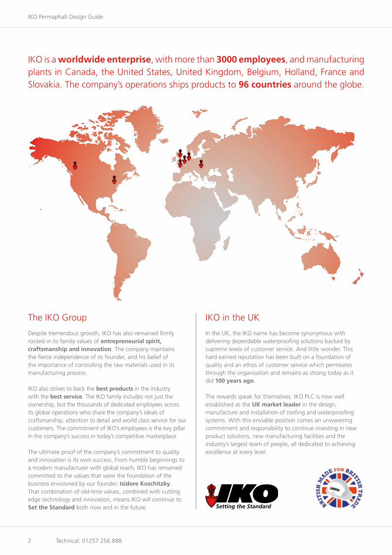
IKO is a worldwide enterprise, with more than 3000 employees, and manufacturing plants in Canada, the United States, United Kingdom, Belgium, Holland, France and Slovakia. The company’s operations ships products to 96 countries around the globe.
The IKO Group IKO in the UK
Technical: 01257 256 888
www.ikogroup.co.uk 3
Contents
The IKO difference 4
History of mastic asphalt 6
A modern construction material 7
Introduction to Permaphalt 8
Roof decks 10
Screeds 11
Falls and drainage 12
Control of condensation 13
Thermal insulation 14
Installation 16
Warm roofs 18
Inverted roofs 26
Permaphalt fullbond 27
Green roofs 28
Terraces and balconies 29
Surface protection and finishes 30
Maintenance and repair 31
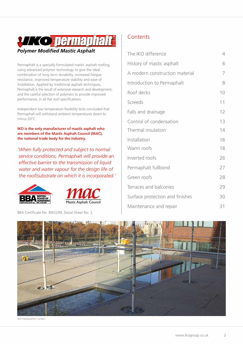
Permaphalt is a specially formulated mastic asphalt roofing, using advanced polymer technology to give the ideal combination of long term durability, increased fatigue resistance, improved temperature stability and ease of installation. Applied by traditional asphalt techniques, Permaphalt is the result of extensive research and development, and the careful selection of polymers to provide improved performance, in all flat roof specifications.
Independent low temperature flexibility tests concluded that Permaphalt will withstand ambient temperatures down to minus 20°C.
IKO is the only manufacturer of mastic asphalt who are members of the Mastic Asphalt Council (MAC), the national trade body for the industry.
‘ When fully protected and subject to normal service conditions, Permaphalt will provide an effective barrier to the transmission of liquid water and water vapour for the design life of the roof/substrate on which it is incorporated.’
BBA Certificate No. 89/2299, Detail Sheet No. 2
IMO Headquarters, London

IKO Permaphalt Design Guide
4 Technical: 01257 256 888
Consultation Survey Design
The IKO Difference
IKO Service
IKO has a highly developed project design and specification service that continually sets new industry standards. Working with our experienced approved installer partners, we have the power to deliver projects on time, on budget and right first time. High performance materials, together with high standards of workmanship and project supervision, provide guaranteed roofing options across the widest specialist product range in the industry.
Orders are handled quickly and accurately, and deliveries to site are arranged according to the contractor’s work schedule, minimising delays on site.
Our specialist roofing knowledge is combined with our strength in structural waterproofing design, ensuring a totally watertight building envelope.
Unrivalled technical support
• Assistance with new-build design• Detailed roof condition surveys, including thermographic
roof imaging• Prioritised roof maintenance schedules
(including roof location plans)• Full written reports (information can be categorised in
accordance with DFE funding criteria)• Comprehensive proposals and specifications
(NBS format available)• Detail design and CAD drawings• Technical advice and calculation facilities• Budget costing• Nationwide network of approved installers• Contract monitoring (work in progress)• Final inspection and guarantee sign-off inspection• Full 20 year insurance-backed guarantees
Memorial to the Missing of the Somme, Thiepval, France
‘ We have the power to deliver projects on time, on budget and right first time.’
Solution

www.ikogroup.co.uk 5
Installation Inspection Guarantee
The IKO Guarantee
The IKO Guarantee is a comprehensive, single-point insurance-backed guarantee covering materials, workmanship and design, for up to 20 years.
IKO Approved Contractors
The success of any project depends upon the skill and training of the operatives installing the waterproofing system.
Our nationwide network of IKO Approved Contractors offers specialist installation services across the whole of theUK. Fully trained operatives ensure the waterproofing system is installed to the highest workmanship and health and safetystandards, whilst national coverage ensures the keenest competitive tendering.
Contractors have to pass a strict selection criteria to gain and maintain accreditation. These include stringent checks on operative training, adequate insurance, health and safety records, quality assurance and financial security.
Norton House Hotel Brecknock School
Mastic Asphalt, the ultimate base for protection and waterproofing, became the first industry in the world to achieve the CarbonZero standard. Working with CO2balance, at IKO we offset the CO2 we produce during the manufacturing process by purchasing Carbon Credits.
Solution

IKO Permaphalt Design Guide
6 Technical: 01257 256 888
Mastic Asphalt FACTS AND FIGURES
MASTIC WATERPROOFSir Christopher Columbus
reportedly used Mastic Asphalt to waterproof his ships as it is unaffected
by water and provides seamless waterproofi ng.
SUSTAINABLE
Potentially 100% recyclable.
LONGILLUSTRIOUS HISTORY
King George V was still on the throne ( 1920’s)when we fi rst started manufacturing.
One 15 tonne hot charge delivery vehicle
can lay 300m2 (20mm).
20402040Durability
One application can last for up to 60 years.Since it became BBA Certifi ed in 1989, IKO Permaphaltinstallations are less than halfway through their lifespan!
IKO plc, MAC (Mastic Asphalt Council), www.bp.com/content/dam/bp-country/en_au/products-services/bp-bitumen/all-pages/Bitumen-basics.pdf
History of Mastic Asphalt
Mastic asphalt is an ideal material for a whole range of construction applications, both new build and refurbishment, where a smooth, seamless, durable surface is required.
It offers total waterproofing integrity for roofing and tanking and acts as a tough working surface in flooring and paving.
Mastic asphalt is one of the world’s most traditional construction materials and has continued to develop with the times, even in today’s hi-tech building industry.
The product comprises suitably graded limestone aggregates bound together with an asphaltic cement (primarily refined bitumens) to produce a dense, voidless material. It cannot be compacted, and is spread by means of a hand float, rather than rolled.
Today’s modern mastic asphalt contains highly advanced polymer formulations, pioneered by manufacturers like IKO in the 1980s.
Mastic asphalt, such as Permaphalt, is installed by trained operatives who have undertaken extensive training programmes.
A very versatile construction material
As a roofing material, mastic asphalt is ideal for use as a waterproof covering over flat, sloped or curved surfaces and can be worked round pipes, roof lights and other projections.
It can be laid on most types of rigid substructure such as concrete, pre-cast concrete deck units, timber boarding, metal decking and other proprietary decking units.
Thermal insulation materials can easily be laid as part of a mastic asphalt specification to give the required U-value.
Treatments applied to asphalt can provide a surface suitable for traffic, increase solar reflectivity and provide a decorative finish.

www.ikogroup.co.uk 7
A Modern Construction Material
‘ Asphalt roofing, properly designed and laid, should prove capable of lasting 50 to 60 years.’Source: Building Research Establishment Digest 144, Asphalt and built-up felt roofing: durability
In harmony with modern methodsof construction
Mastic asphalt has kept pace with today’s technology. Permaphalt’s advanced polymer formulation makes it the perfect choice for any roofing application. It offers low temperature flexibility, high temperature stability and long term durability.
A roofing system which includes Permaphalt achieves the highest fire performance ratings, improves acoustic performance and offers proven performance when laid over modern thermal insulation materials.
A further major benefit for larger projects, Permaphalt can be laid at speed when supplied to site in bulk by hot charge transporters and insulated dumpers. It can be delivered to site direct from the factory for instant installation.
By this method, one 18 tonne hot charge delivery vehicle can supply enough Permaphalt to lay 360m2 of material to a depth of 20mm. This ensures that a roof can be quickly and efficiently waterproofed allowing other trades on site, often within hours.
Many design possibilities
Permaphalt offers the architect more scope for design opportunities. Because it is totally seamless, Permaphalt is ideal for roof gardens, paved areas, leisure complexes or any situation where general aesthetics have to be combined with good waterproofing. Furthermore it is an exceptionally versatile material which can be moulded to follow any shape or contour.
Durability and stability
Permaphalt has improved high temperature stability and is more flexible at low temperatures than conventional mastic asphalt. When fully protected and subject to normal service conditions, Permaphalt will perform for the design life of the roof on which it is incorporated.
Resistance to loading and foot traffic
Permaphalt can accept, without damage, the limited foot traffic and light concentrated loads associated with installation and maintenance operations. Where access exceeding this is envisaged, attention should be taken over the thickness and surface protection specified.
Westfield, Derby

Permaphalt Polymer Modified Mastic AsphaltUnrivalled Versatility, Unrivalled Performance
IKO Permaphalt Design Guide
8 Technical: 01257 256 888
Page 18 – Warm Roofs Page 26 – Inverted Roofs
Page 27 – Permaphalt Fullbond
Page 28 – Green Roofs Page 29 – Terraces and Balconies
www.ikogroup.co.uk 9
Typical uses
General flat roofingPermaphalt can be applied to form a continuous waterproof covering over flat, sloped or curved surfaces.
It can be worked round pipes, roof lights and other projections to provide a completely seam free membrane.
Permaphalt is suitable for use on most types of roof decks such as concrete, timber and profile metal. Permaphalt can be used on insulated warm roofs, un-insulated cold roofs and inverted roof specifications.
Balconies and terracesThe durability of Permaphalt makes it an ideal waterproof covering for areas subjected to regular foot traffic. It can be laid as the surface finish or beneath promenade tiles or paving slabs.
Green roofsPermaphalt is also ideal for both intensive and extensive green roof systems. It is fully resistant to root penetration and does not require a separate root barrier.
Fully protected within a roof garden system, Permaphalt will provide a waterproof membrane for the design life of the roof.
Key features and benefits
• Manufactured in the UK under the BS EN ISO 9001, Quality Assurance Scheme
• ISO 14001 & BES 6001• BBA certified• BRE assessed• Loss Prevention Certification Board (LPCB) Approved -
Certificate No. 666A• Fire Performance achieving BS 476: Part 3: FAA• Advanced polymer modification• Completely seamless waterproofing• Long term durability• Enhanced product stability across a wide temperature range• High fatigue resistance• Traditional application• No mechanical fixings to penetrate vapour control layer• Permaphalt installations are covered by the comprehensive
range of long term guarantee packages.
Composition and manufacture
Permaphalt is manufactured in the UK under the BS EN ISO 9001, Quality Assurance Scheme.
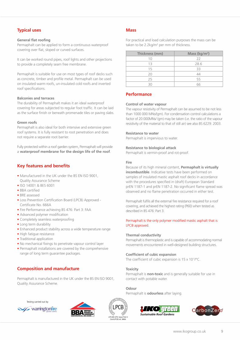
Mass
For practical and load calculation purposes the mass can be taken to be 2.2kg/m2 per mm of thickness.
Thickness (mm) Mass (kg/m2)10 22
13 28.6
15 33
20 44
25 55
30 66
Performance
Control of water vapourThe vapour resistivity of Permaphalt can be assumed to be not less than 1000 000 MNs/(gm). For condensation control calculations a factor of 20 000MNs/ (gm) may be taken (i.e. the ratio of the vapour resistivity of the material to that of still air) see also BS 6229: 2003.
Resistance to waterPermaphalt is impervious to water.
Resistance to biological attack Permaphalt is vermin-proof and rot-proof.
FireBecause of its high mineral content, Permaphalt is virtually incombustible. Indicative tests have been performed on samples of insulated mastic asphalt roof decks in accordance with the procedures specified in (draft) European Standard prEN 1187-1 and prEN 1187-2. No significant flame spread was observed and no flame penetration occurred in either test.
Permaphalt fulfils all the external fire resistance required for a roof covering, and achieved the highest rating (P60) when tested as described in BS 476: Part 3.
Permaphalt is the only polymer modified mastic asphalt that is LPCB approved.
Thermal conductivityPermaphalt is thermoplastic and is capable of accommodating normal movements encountered in well-designed building structures.
Coefficient of cubic expansionThe coefficient of cubic expansion is 15 x 10-5/°C.
ToxicityPermaphalt is non-toxic and is generally suitable for use in contact with potable water.
OdourPermaphalt is odourless after laying.
LPS BS 476: Issue Part 3Cert/LPCB ref. 666A
Testing carried out by

IKO Permaphalt Design Guide
10 Technical: 01257 256 888
Roof Decks
General
The structural deck provides the primary support for the roofing system. It must resist dead, live and wind loads, including storms. It must also be suitable for the proposed Permaphalt roofing system, and subsequent use. Relevant structural and loading codes for each material must be followed, and the requirements of the current Building Regulations must be checked and observed. If the use of the roof is to be changed, the suitability of the deck and the structure must be re-confirmed.
The deck may also be laid or fixed so as to provide a suitable fall for drainage of the roof surface, as required in BS 6229, Code of Practice for flat roofs with continuously supported coverings.
The most common types of flat roof structural deck are:
In-situ concrete decksCast in-situ reinforced concrete decks can be laid to achieve an adequate fall, or a separate screed to falls, such as Permascreed, can be used. The finished surface must be adequately dry to accept the specified Permaphalt roof waterproofing system, andfree of any ridges or hollows. The most suitable surface is provided by a wood float finish. Construction water should be drained by forming temporary drainage holes through the slab, as specified in BS 6229.
Pre-cast concrete decksA variety of pre-cast deck units are available, and these should be used and fixed in accordance with manufacturer’s instructions. A screed is normally required to provide an even surface for waterproofing and to provide drainage falls, if falls cannot be incorporated in the supporting structure. Construction water should be minimised, and where present, drained by leaving the deck joints open on the underside.
Timber-based panelsTimber and timber products (including plywood and OSB) must conform to the Construction Products Directive (CPD) for structural use, as covered in BS EN 13986, and should be marked ‘CE2+ Structural’. Timber and timber products for structural use should also comply with BS 5268-2.
Timber panels are subject to moisture and thermal movement. They should be fixed with a minimum of 3mm gap between panels, and 10mm at roof edges/perimeters (for further guidance contact the panel manufacturer). Generally, corrosion-resistant round headed ring-shanked nails or suitable screws should be used at 150mm centres around perimeters and 300mm centres on intermediate supports. The fixings should be long enough to penetrate at least 35mm into the supporting joists and noggins. Nail and screw heads must be driven down below the deck surface.
Plywood decksPlywood is available as a square-edged or tongue and grooved panel. The plywood should conform to the relevant requirementsof BS EN 636, Clause 7 regarding use in humid conditions, and Clause 8 regarding exterior use. Materials suitable for flat roofingwould be marked ‘BS EN 636–2’ or ‘BS EN 636–3’. Plywood should be of exterior or WBP glue type and of a quality and thickness suitable for structural applications. All joints and edges should be fully supported.
Oriented strand board (OSB)Oriented strand board grade 3 (OSB 3) has been developed as a suitable alternative to structural grade plywood. It is an engineered wood product, manufactured from orientated wood flakes combined with an exterior grade resin and compressed under high temperature.
The result is a load-bearing panel suitable for structural use in flat or pitched roofing, but is restricted from high humidity roofs, such as swimming pools. OSB 3 is available as a square-edged or tongue and grooved panel. Only OSB 3 manufactured to BS EN 300 and marked as such should be used in roofing. OSB 4 would also be suitable, but is not generally available in the UK. Ideally such products should have third-party certification.
Woodwool decksWoodwool is an open textured board (or slab) composed of wood strands bound together with a cement mixture. It was used as a roof deck material from the mid-1950s until the late 1990s. Woodwool is no longer manufactured in the UK, and is now regarded as a ‘fragile material’ under the guidance in HSG33 from the Health and Safety Executive. Works on roofs with such decks need a careful risk assessment agreed beforecommencement.
Metal deckingProfiled metal roof decking should be manufactured either in:galvanised steel, to BS EN 10326, or aluminium sheet, to BS EN 485-2. All use of profiled steel sheeting should comply with BS EN 1993-1-3. There is a wide range of metal profiles and thicknesses for various load/span relationships, usually over steel supporting structures.
A profiled metal deck does not provide a continuous supporting upper surface and requires covering with plywood, OSB 3 or insulation to enable Permaphalt to be laid.

www.ikogroup.co.uk 11
Screeds
Screeds provide a suitable surface to receive Permaphalt and can also be used to achieve falls and cross-falls. In addition, some screeds can provide a level of thermal insulation and contribute to the U-value of the roof.
Other screeds
Sand and cement screeds Sand and cement screeds are normally mixed in the ratio 4:1 and the surface should be finished with a wood float. The screed should be laid directly onto the deck to obtain a good key. It should be laid in areas not exceeding 10m², to reduce the incidence of cracking due to drying and shrinkage. These screeds contain considerable amounts of water and the surface should be adequately cured and dry before the Permaphalt roofing specification is applied. Where screeds are formed or supported on permanent shuttering or metal profiles, provision must be made for water to drain adequately, in accordance with the manufacturer’s instructions.
Aerated screedsAerated screeds consist of Portland cement, water and a foaming emulsion, which are combined to produce a cellular material; thisoffers a hard surface when dry.
Lightweight aggregate screeds (cement bonded)Suitable lightweight aggregates are formed from expanded clay or sintered pulverised fuel ash, bonded with a cement binder. The material must be laid soon after mixing, otherwise the cement binder could dry too fast, and not bond the aggregate together.A 13mm sand and cement topping is necessary to provide a smooth level surface for the roofing specification.
Insulating cement screedsA range of cement based screeds containing Perlite, Vermiculite, recycled EPS and other additives are available from various sources. These are often of a lighter weight than just sand and cement and impart a degree of insulation to the roof structure. Guidance on the thermal performance and installation of these products must be sought from the individual manufacturer concerned.
IKO black sheathing felt loose laid with 50mm lap joints
Enertherm PIR MG insulation board
Permascreed laid to required falls
IKO Glass Universal T-O underlay16m fully bonded by torch application.Underlay can be specified to act astemporary weatherproofing
Concrete deck
20mm 2 coat Permaphaltwith solar reflective finish
Enertherm water control layer
Enertherm XPS insulation board
Geotextile isolating membrane
20mm 2 coat permaphalt
2 layers of IKO glass fibre tissueloose laid with 50mm lap joints
Permascreed laid to required falls
Concrete deck
IKO Glass Universal T-O underlay16m fully bonded by torch application.Underlay can be specified to act astemporary weatherproofing
50mm pre-cast paving slabson pads or ballast
Permascreed
Permascreed mastic asphalt screed is manufactured from selected bitumens, limestone filler and specially graded aggregates. It is designed to provide drainage falls as well as a stable base for the specified roof waterproofing system. Permascreed can be applied at a wide range of thicknesses (minimum 10mm) and falls, usually on in-situ and pre-cast concrete bases. It is suitable for insulated warm roofs, inverted roofs, green roofs and balcony/terrace applications. A major advantage of this type of screeding is that the laid material can be accessed and the waterproofing installed as soon as the Permascreed has cooled to ambient temperature. Permascreed will accept, without damage, the type of traffic and concentrated loads associated with the installation of a flat roof waterproofing system.
Features and benefits• Rapid cooling• Fast-track application - avoids extended curing time
associated with wet screeds• Ideal for both new build and refurbishment projects• Can be trafficked or covered as soon as it has cooled
to ambient temperature• Provides temporary roof waterproofing• Avoids the need for a separate vapour control layer• Can be laid to a wide range of falls and thicknesses
(minimum thickness 10mm at low points)• Does not require compaction• Easily worked around roof protrusions.
Inverted roof refurbishment
Warm roof refurbishment

IKO Permaphalt Design Guide
12 Technical: 01257 256 888
Falls and Drainage
Design of falls
It is generally accepted as good practice for flat roofs to be designed to clear surface water and it would be unusual for aPermaphalt roof to be designed without falls, other than within a three coat protected membrane or Permaphalt Fullbond specification.
Flat roofs should be constructed to a minimum fall of 1 in 80. To achieve this, the designer needs to adopt a design fall which will allow for deflections and inaccuracies in construction. BS 6229 recommends 1 in 40 as the design fall, to ensure a finished fall of at least 1 in 80. An alternative approach is to choose an intermediate figure of 1 in 60, which is usually sufficient.
The design of falls and drainage patterns will have a considerable influence on the depth of the total roof construction or roof zone, which should be a fundamental consideration at the very earliest stages of conception of a building. It is only after assessing the depth of roof zone that the designer can decide the levels of all other aspects of construction above the level of the flat roof.
Falls may be formed in the structure or can be created within the specification above the deck. Falls in the structure can be achieved by adjusting the height of supporting beams or purlins, by using tapered supports, or by the addition of firring pieces before the deck is laid. The latter method is normally used with decks such as woodwool, timber, precast concrete and metal decking. In the case of an in-situ cast concrete slab, falls are normally provided by using a screed, such as Permascreed.
Preformed tapered insulation boards also provide a useful method of forming falls on a level roof deck. IKO is able to design and supply suitable tapered insulation systems. These provide both insulation and falls and are of particular importance for reroofing existing roofs, many of which do not have sufficient falls and probably do not have sufficient insulation.
Tapered insulation can provide falls in one direction to a gutter or level valley, or in two directions to form falls and cross falls.In some circumstances it may be deemed necessary to control the rate of water run-off from flat roofs and paved areas so as to avoid overloading ground drainage. Where this is a requirement, consideration should be given to using green roofs or roof top gardens where the horticultural finishes can be used to absorb rainfall and release it into surface water more slowly. However, it is still important to make the correct provision for adequate drainage, even with garden roofs, to avoid water-logging the growing medium or overloading the structure.
Note: The requirement for drainage falls may be avoided by specifying the inverted roof system (see page 26) or full bond system (see page 27).
Roof drainage
Flat roofs may be drained by two basic methods: Towards the outer edges and into external gutters, or towards internal gutters or outlets within the main roof area. Straight falls to external gutters are simple to form by sloping the roof deck, by screeding or by using tapered insulation boards. Internal drainage will be achieved by straight falls to gutters or a pattern of falls and cross falls to outlets.
Riverside, Barking

www.ikogroup.co.uk 13
Control of Condensation
When designing a roof, the problem of condensation must always be considered. Any provision required to controlcondensation should be determined as recommended in BS 6229 but with the calculation method modified to conform with BS 5250, Code of Practice for control of condensation in buildings.
In the case of a roof incorporating Permaphalt, a suitable thermal insulation may be included within the system. This layer must have sufficient insulation value for its underside to remain above the temperature at which condensation can start, even on the coldest nights. The provision of insulation alone, however, may not be sufficient to prevent condensation. If the insulation is permeable to water vapour, the vapour will pass upwards through it and condense on the underside of the waterproof membrane (Fig. 1).
20mm two-coat Permaphalt
Black sheathing felt
Enertherm PIR MGinsulation
13mm Permaphalt vapour barrieron glass fibre tissue
Vapour rises
20mm two-coat Permaphalt
Black sheathing felt
Enertherm PIR MGinsulation
Condensation
Vapour rises
Fig. 1 No vapour control layer - condensation occurring Fig. 2 Typical warm roof section showing vapour control layer
To prevent this happening a vapour control layer in the form of a vapour barrier should be provided on the underside of the insulating layer (Fig. 2). A vapour barrier can be an approved metal lined vapour barrier or 13mm think single coat of Permaphalt roofing on an underlay of glass fibre tissue.
Note: The need for a separate vapour control layer may be avoided by specifying the inverted roof system (see page 26) or full bond system (see page 27).
IKO Permaphalt Design Guide
14 Technical: 01257 256 888
Thermal Insulation
General
The statutory requirements for the thermal performance of buildings in England and Wales is set out in Building Regulations 2010 Part L as amended for existing buildings and Building Regulations 2013 Part L for new buildings.
The new Part L is published in four sections:
L1A: New dwellingsL1B: Existing dwellingsL2A: New buildings other than dwellingsL2B: Work in existing buildings other than dwellings.
Scotland and Northern Ireland are subject to local regulations.
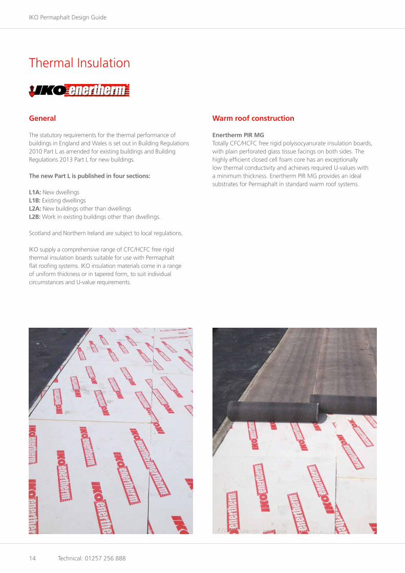
IKO supply a comprehensive range of CFC/HCFC free rigid thermal insulation boards suitable for use with Permaphalt flat roofing systems. IKO insulation materials come in a range of uniform thickness or in tapered form, to suit individual circumstances and U-value requirements.
Warm roof construction
Enertherm PIR MGTotally CFC/HCFC free rigid polyisocyanurate insulation boards, with plain perforated glass tissue facings on both sides. The highly efficient closed cell foam core has an exceptionally low thermal conductivity and achieves required U-values with a minimum thickness. Enertherm PIR MG provides an ideal substrates for Permaphalt in standard warm roof systems.

www.ikogroup.co.uk 15
Inverted roof construction
Enertherm XPSA CFC/HCFC free extruded polystyrene insulation, for use above Permaphalt in all inverted roof specifications. Enertherm XPSis resistant to water and will provide long term protection to the Permaphalt waterproofing.
U-value guidance
The following table is intended to be used for guidance only, but gives approximate thermal resistance (U-value) figures for our range of thermal insulations based on the followingconstruction build up:
20mm Permaphalt - separating layer(s) - selected insulation - metal lined vapour barrier - 150mm concrete deck with nominal50mm sand/cement screed - ceiling void - 13mm plasterboard – 2mm plaster skim.
The Enertherm XPS figures are based on a typical inverted roof construction build up of 50mm paving slabs on proprietary supports - Enertherm XPS with WCM layer aboveand filtration layer beneath - 20mm Permaphalt - separating layer - 150mm concrete deck with nominal 50mm sand/cement screed - ceiling void - 13mm plasterboard - 2mm plaster skim.
For applications not covered in the table, please contact Technical Services (01257 256 888):
Target U-value Enertherm PIR MG Enertherm XPS (with WCL)
0.25 100mm 130mm
0.20 120mm 160mm
0.18 140mm 180mm
0.16 150mm 200mm
0.15 150mm 220mm
General Post Office, Edinburgh

IKO Permaphalt Design Guide
16 Technical: 01257 256 888
Installation
Separating layers
A separating layer is traditionally required on horizontal layers to isolate the Permaphalt from joint movement in the substrate but still provide a significant friction to help restrain the asphalt against contraction in cold weather. It allows a free lateral passage for hot air and moisture vapour during the application of the hot Permaphalt and acts as a long term vapour pressure release layer. Separation is provided by black sheathing felt which is laid entirely loose with lap joints of 50mm. Over Permascreed, 2 layers of IKO Glass Fibre Tissue laid loose and staggered with 50mm laps is required.
Keying to surfaces
ConcreteWhere vertical or sloping concrete is very smooth (e.g. where steel shuttering has been used), the surface laitance should be removed by wire brush or suitable mechanical means to provide a satisfactory key for the Permaphalt.
Note: Damage to Permaphalt and loss of key will be caused by excessive use of mould oil.
Apply a light brush coat of IKOpro High Bond Primer and allow to dry thoroughly before applying Permaphalt. Where excessive blowing is experienced the fixing of bitumen coated expanded metal lathing over black sheathing felt may be required.
Permaphalt cannot be applied directly to lightweight concrete or lightweight concrete blockwork, which should be rendered with a suitable sand cement facing, or have galvanised expanded metal lathing on sheathing felt fixed at a maximum 150mm centres.
BrickworkJoints in brickwork should be flush pointed. The surface must be cleaned and IKO’s High Bond primer applied to avoid blistering or loss of bond.

www.ikogroup.co.uk 17
TimberThe key to vertical or sloping timber surfaces is obtained by fixing galvanised expanded metal lathing over black sheathing felt fixed by nailing with extra large head galvanised felt nails or with galvanised staples at maximum 150mm centres.
Application of Permaphalt
The application of Permaphalt should be in accordance with BS 8218 and BS 8000: Part 4 and IKO’s recommendations.
Flat roofs up to 10° Permaphalt is normally laid in two coats, breaking joint, to nominal thickness of 20mm on an underlay of black sheathing felt laid loose with 50mm lapped joints. Where thermal insulation is laid beneath the weatherproofing, it is recommended that the roof pitch does not exceed 5°.
Slopes over 10° and vertical surfaces (excluding skirtings)Permaphalt laid on concrete or screeded substructures of 10° to 30° slope is applied in two coats to a nominal thickness of 20mm direct to the concrete.
For vertical work over 300mm and slopes over 30°, Permaphalt is applied in three coats, the first coat being applied very thinly with a steel trowel or small wooden float. A further two coats are then applied, breaking joint, to give a nominal thickness of 20mm. For these applications the concrete must be left with aroughened surface to form a key for the Permaphalt.
In the case of sloping timber surfaces over 10°, a layer of black sheathing felt is first nailed to the timber. Galvanised expandedmetal lathing is then fixed at 150mm centres with galvanised clout nails or staples to form a key for the Permaphalt which is applied in three coats to a nominal thickness of 20mm.
Sand rubbingWith the exception of vertical and steeply sloping work, clean sharp sand should be rubbed evenly into the finished surface of the asphalt with a wooden float while it is still hot. This rubbing breaks up the skin of bitumen brought to the surface at the time of application. Gradual crazing of the surface due to the action of the sun is minimised by sand rubbing in this way.

IKO Permaphalt Design Guide
18 Technical: 01257 256 888
Warm Roofs
A warm roof has the principle thermal insulation placed above the structural deck, but beneath the waterproofing layer. This is the most specified Permaphalt flat roof specification.
In the following pages typical Permaphalt specifications and details are illustrated for the most commonly encountered forms of flat roof construction. IKO can advise on any situation not covered.

www.ikogroup.co.uk 19
Skirtings and flashings
In the case of concrete, brickwork and similar sub-structures, a two-coat Permaphalt skirting is necessary at all upstands to anominal thickness of 13mm and a minimum height of 150mm above finished roof level. A two-coat angle fillet should be formed at the junction of the vertical and the flat. The top of the skirting is splayed and turned into a chase 25mm x 25mm unless the asphalt continues horizontally. Skirtings above 300mm high are regarded as ‘shown vertical’ and Permaphalt is applied in three coats to a nominal thickness of 20mm.
Where differential movement is likely to occur between the roof deck and upstands e.g. substrates consisting of timber board, woodwool slabs or metal, a free standing upstand fixed to the deck, a minimum 12mm clear of walls and abutments is necessary.
This is usually provided by a timber kerb or metal angle with plywood facing. Permaphalt is then applied in three coats to a total thickness of 20mm on to expanded metal lathing fixed over black sheathing felt. The skirting is cover-flashed and protected by an application of solar reflective paint. Where insulation is used beneath Permaphalt, but not continued up the verticals, a minimum 25mm wide support leg to the skirting is essential.
Sand and cementpointing
Bottom edge ofchase removed
25mm
25mm
DPC
Metal cover flashing
Black sheathing felt Two-coat angle fillet
Expanded metal lathing
Vapour control layer
Enertherm PIR MG insulation
Black sheathing felt
Permaphalt skirting
Metal cover flashing
Fig. 3 Typical chase to concrete upstand Fig. 4 Typical chase to brick wall Fig. 5 Typical free standing kerb

IKO Permaphalt Design Guide
20 Technical: 01257 256 888
Parapets and boundary walls
20mm two-coat Permaphalt
Black sheathing felt
Vapour control layer
Enertherm PIR MG insulation
13mm two-coat Permaphalt skirting
Two-coat angle fillet
Metal cover flashing
150mmminimum
Metal cover flashing
20mm two-coat Permaphalt
Enertherm PIR MG insulation
20mm three-coat Permaphalt
Pressed metal closure
External cladding
150mmminimum
Minimum 19mm plywood upstand fixed to metal angle
Two-coat angle fillet
20mm two-coat Permaphalt
Black sheathing felt
Vapour control layer
Timber decking
Firrings on joists
Enertherm PIR MG insulation
Expanded metal lathing
Free-standingtimber kerb
Support leg
20mm three-coat Permaphalt skirting
Metal cover flashing
150mmminimum
Fig. 6 Typical warm roof skirting to brick wall Fig. 7 Typical warm roof skirting to timber kerb
Fig. 9 Typical insulated warm roof skirtingig. 8 Typical warm roof skirting to metal deck
Metal flashing
Timber fillet
Minimum 19mm plywoodupstand fixed over insulation
20mm three-coat Permaphalt
20 mm two-coat Permaphalt
Black sheathing felt
Expanded metal lathing
Enertherm PIR MG insulation
Vapour control layer
150mmminimum

www.ikogroup.co.uk 21
Verges
Perimeter kerbs may be completed with a GRP edge trim fixed at 300mm max. centres. Alternatively, an asphalt apron with anundercut drip may be formed.
GRP edge trim
20mm two-coat PermaphaltSolid Permaphalt
watercheck
Solid Permaphaltwatercheck
Enertherm PIR MG insulation
Permaphaltapron
InsulatedHard Edge
GRP edge trim
Expanded metal lathing
20mm three-coat Permaphalt
20mm two-coat Permaphalt
20mm two-coat Permaphalt
20mm two-coat Permaphalt
Black sheathing felt
GRP edge trim
13mm two-coat Permaphalt
Fig. 12 Typical check kerb
Fig. 11 Typical concrete kerb
Fig. 10 Typical verge options
Enertherm PIR MG insulation
Enertherm PIR MG insulation
Enertherm PIR MG insulation

IKO Permaphalt Design Guide
22 Technical: 01257 256 888
Rainwater outlets
A number of outlets can be used in conjunction with Permaphalt but cast iron or spun aluminium outlets with a bellmouth and internal clamp ring are particularly recommended.
Where a syphonic drainage system is required, the outlets must be designed specifically for use with mastic asphalt. For further details please contact Technical Services.
At outlets though parapet walls Permaphalt is lapped onto a pre-formed lead chute which is taken through the wall into a hopper head.
Enertherm PIR MG insulation
Insulated hard edge
Black sheathing felt
Expanded metal lathing
20mm two-coat Permaphalt
Internal clamping ring
Metal grating
Permaphalt dressed into outlet
Two-coatangle fillet
Fig. 13 Typical rainwater outlet
Gutters
Where the roof fall is into an eaves gutter the asphalt can be finished over a lead flashing set into a rebate in the sub-structure. The lead must be welted at the back and the depth of the rebate must allow for a full thickness of Permaphalt over the welt. Alternatively, a Permaphalt apron or proprietary GRP Edge Trim can be used.
Gutters can be lined in Permaphalt to follow any shape of contour in the sub-structure. Where a gutter is formed between a parapet wall and a tiled or pitched roof, the Permaphalt is carried up the slope and over the tilting fillet.
It is generally preferable to avoid the use of integral gutters on flat roofs, using instead, falls and cross falls to direct the flow of water to rainwater outlets.
Underslating felt
Permaphalt over t iling fillet
Expanded metal lathing
Black sheathing felt
Two-coat angle fillet
Concrete deck
Separating membrane
Permaphalt apron
Fig. 14 Typical box gutter
Fig. 15 Typical eaves gutter
Enertherm PIR MG insulation
Enertherm PIR MG insulation

www.ikogroup.co.uk 23
Movement joints
Twin kerb movement joints are recommended with a metal cap flashing fixed to one kerb only, or a capping system held by cleats or spring clips. In either case suitable fixings should be provided to avoid penetrating the asphalt.
All ends should be boxed as necessary to complete the waterproofing but still allow movement.
The design of the structure should avoid flush surface movement joints if at all possible. However, proprietary systems are available for this application and seeking specialist advice is necessary.
Projections through roofs
Projections passing through the roof, such as handrails, stanchions and metal pipes, can usually receive a Permaphalt collar direct. Permaphalt is dressed 150mm above finished roof level and the upper edge protected with an apron flashing. In situations where Permaphalt can not be applied directly to theprojection, a lead sleeve should be fixed to the substrate.
Black sheathing felt
Enertherm PIR MG insulation
20mm Permaphalt
Metal cleats fixedin concrete
Metal hood
13mm two-coat Permaphalt to kerb
Two-coat angle fillet
Fig. 16 Typical movement joint
Handrail
Apron flashing
Black sheathing felt
150mm
Fig. 17 Typical roof projection
Enertherm PIR MG insulation

IKO Permaphalt Design Guide
24 Technical: 01257 256 888
Rooflights and ventilators
Rooflights and ventilators should be mounted on kerbs minimum 150mm above the roof finish. Permaphalt is then taken up the side and over the top of the kerb. Proprietary kerb adaptors are recommended for such details and these must be applied before the roof light is fixed. Advice on the suitability of PVC and metal roof light kerbs to receive Permaphalt directly must be obtained from the manufacturer. However, a timber facing fixed to the kerb followed by expanded metal lathing fixed over black sheathing felt would normally be required.
Metal rooflight or ventilator kerb
20mm three-coat Permaphalt
20mm two-coat Permaphalt
Expanded metal lathing
150mmminimum
Fig. 18 Typical rooflight
Enertherm PIR MG insulation
Plinths
Plinths to receive rooftop equipment must be constructed off the deck or screed level. Permaphalt is dressed in a minimum 150mm above finished roof level and the top protected with a cover flashing.
Metal and neoprenewashers
Metal cover flashing
13mm two-coatPermaphalt to primed base
150mmminimum
Fig. 19 Typical plinth
Enertherm PIR MG insulation

www.ikogroup.co.uk 25
Change of level
20mm two-coat Permaphalt
Vapour control layer
Two coat angle fillet
Enertherm PIR MG insulation
Black sheathing felt
Expanded metal lathing
20mm three-coat Permaphalt
Insulated hard edge
Fig. 20 Typical change of level
Mansards
Fig. 21 Typical mansard
Roof tiles
Lead apron set in recess
20mm two-coat Permaphalt
Tilt fillet support
Insulated hard edge
Enertherm PIR MG insulation
Vapour control layer
IKO Permaphalt Design Guide
26 Technical: 01257 256 888
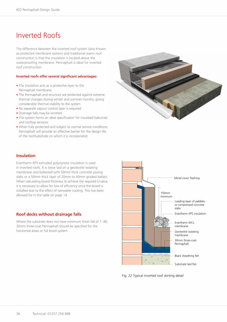
Inverted Roofs
The difference between the inverted roof system (also known as protected membrane system) and traditional warm roof construction is that the insulation is located above the waterproofing membrane. Permaphalt is ideal for inverted roof construction.
Inverted roofs offer several significant advantages:
• The insulation acts as a protective layer to the Permaphalt membrane
• The Permaphalt and structure are protected against extreme thermal changes during winter and summer months, giving considerable thermal stability to the system
• No separate vapour control layer is required• Drainage falls may be omitted• The system forms an ideal specification for insulated balconies
and rooftop terraces• When fully protected and subject to normal service conditions,
Permaphalt will provide an effective barrier for the design life of the roof/substrate on which it is incorporated.
Insulation
Enertherm XPS extruded polystyrene insulation is used in inverted roofs. It is loose laid on a geotextile isolating membrane and ballasted with 50mm thick concrete paving slabs or a 50mm thick layer of 20mm to 40mm graded ballast. When calculating board thickness to achieve the required U-value it is necessary to allow for loss of efficiency once the board isinstalled due to the effect of rainwater cooling. This has been allowed for in the table on page 14.
Roof decks without drainage falls
Where the substrate does not have minimum finish fall of 1: 80, 30mm three-coat Permaphalt should be specified for thehorizontal areas or full bond system.
Metal cover flashing
Loading layer of pebbles or compressed concreteslabs
Enertherm WCLmembrane
Enertherm XPS insulation
Geotextile isolatingmembrane
30mm three-coatPermaphalt
150mmminimum
Black sheathing felt
Substrate laid flat
Fig. 22 Typical inverted roof skirting detail

www.ikogroup.co.uk 27
Permaphalt Fullbond
Features and benefits• BBA certification• Loss Prevention Certification Board (LPCB) Approved - Certificate No. 666A• Fire Performance achieving BS 476: Part 3: FAA• Advanced polymer modification• Completely seamless waterproofing• Fully bonded to substrate• Long term durability• Enhanced product stability across a wide temperature range• High fatigue resistance• Traditional application• Manufactured in the UK under BS ISO 9001 Quality Assurance Scheme.
Permaphalt Fullbond is a fully bonded polymer modified mastic asphalt roof waterproofing system for concrete decks. The Permaphalt Fullbond system comprises of Permaphalt and a torch-on underlay, fully bonded to the concrete substrate, thereby eliminating lateral tracking of moisture, directly beneath the waterproofing layer. Full bond is suitable for inverted flat roofs, completely flat decks, podiums, green roofs and roof gardens.
Note: There is no Figure 23 in this brochure.

IKO Permaphalt Design Guide
28 Technical: 01257 256 888
Green Roofs
Features and benefits• Enhances environment• Improves aesthetic appearance• Controls storm water run-off into surface
water drainage system• Reduces noise transmission by
upgrading acoustic performance• Improves thermal performance• Improves ambient air quality• Increases life expectancy of
waterproofing membrane• Extensive green roofs require little
longterm maintenance• Intensive roof gardens can be accessed
for recreational use.
Drainage/f ilter layer
25mm growing medium
40mm sedum finish
Vegetation barrier
Protection board
20mm two-coat Permaphalt
Fig. 24 Typical extensive green roof (warm roof option)
Enertherm PIR MG insulation
Permaphalt is an ideal waterproofing material for extensive green roofs, intensive roof gardens and biodiversity roofs. It is completely resistant to root penetration and does not require an additional anti-root barrier.

www.ikogroup.co.uk 29
Terraces and Balconies
Where insulation is incorporated beneath Permaphalt on balconies and terraces, or in situations where point loading is anticipated, promenade surfacing should be provided by suitable concrete tiles or paving slabs.
The smooth level surface of Permaphalt forms a good base for the application of porous concrete tiles bedded in bitumen or GRC tiles bonded in a suitable PU Adhesive, in accordance with manufacturers’ instructions.
Adequate drainage falls should be provided on balconies and terraces to prevent ponding water.
Fig. 25 Typical balcony detail
Step slab
25mm x 25mm chase
13mm two-coat Permaphaltskirting
Two-coat angle fillet
Porous concrete tiles
20mm two-coat Permaphalt
Black sheathing felt
Enertherm PIR MG insulation
Vapour control layer
Minimum 25 mm wide support Permaphalt plug
Structural deck to falls
150 mmminimum
Where Permaphalt is required as an exposed paving subjected to foot traffic only, it is laid in two coats to a nominal thickness of 25mm. The first coat is laid to a thickness of 10mm and the second coat 15mm incorporating 15% by weight of coarse aggregate.
IKO Permaphalt Design Guide
30 Technical: 01257 256 888
Surface Protection and Roof Finishes
Surface protection
With the exception of vertical and steeply sloping work, the finished Permaphalt must be sand rubbed to reduce the incidence of crazing.
Where Permaphalt is laid onto insulation in a warm roof construction, a protective surface should be applied to all flat areas using a suitable solar reflective paint such as Solaflect, stone chippings or promenade surfacing.
Solar reflective paint
Exposed asphalt skirtings and vertical areas will require an approved reflective paint to provide adequate protection for Permaphalt. Periodic repainting will be required.
Stone chippings
A single layer of 10 to 14mm dust free stone chippings will act as a permanent surface protection for the full life of Permaphalt.
When the chippings are well bonded to the asphalt removal can be difficult and therefore it is preferable to provide a minimum bond to ensure that they remain in place. This can be achieved by using a cold applied bitumen solution such as IKOpro Chipping Compound.
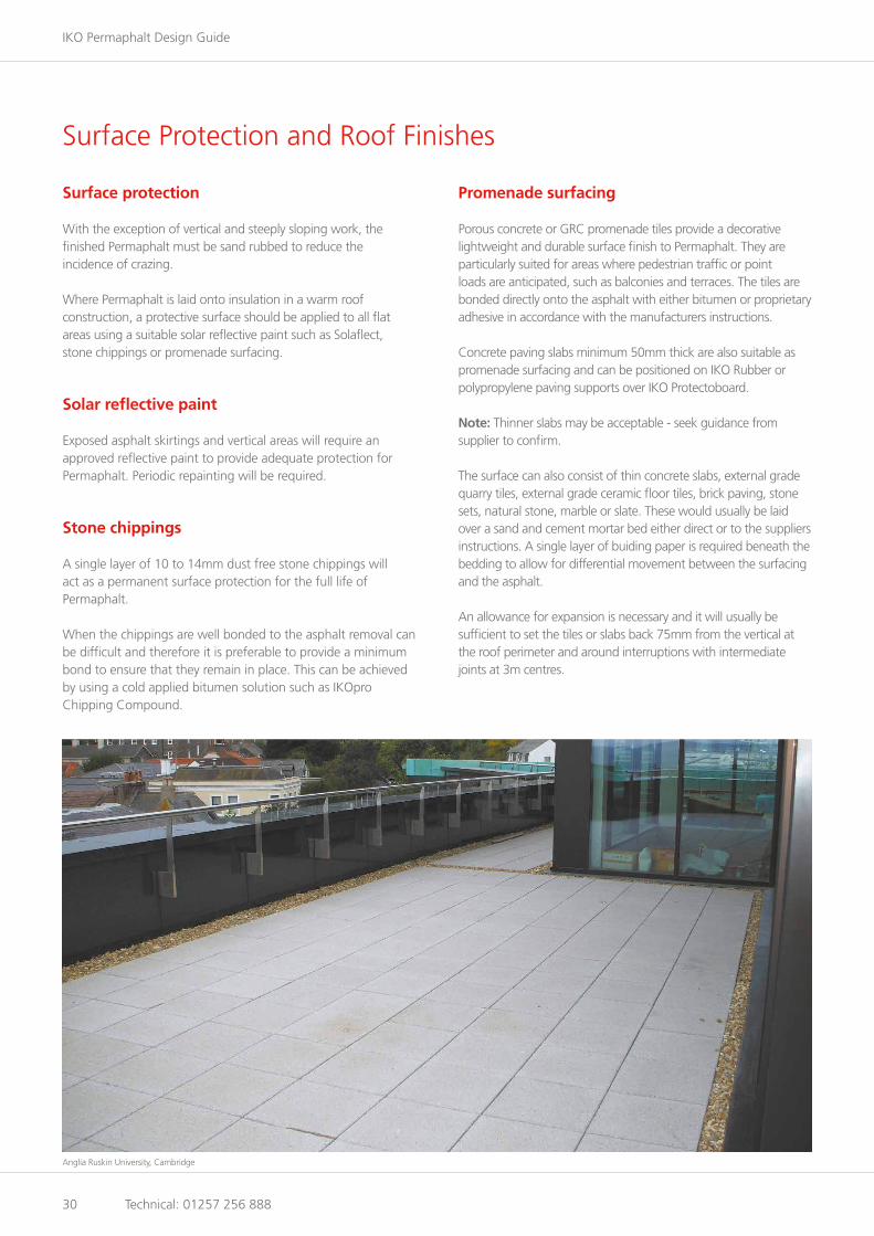
Promenade surfacing
Porous concrete or GRC promenade tiles provide a decorative lightweight and durable surface finish to Permaphalt. They areparticularly suited for areas where pedestrian traffic or point loads are anticipated, such as balconies and terraces. The tiles are bonded directly onto the asphalt with either bitumen or proprietary adhesive in accordance with the manufacturers instructions.
Concrete paving slabs minimum 50mm thick are also suitable as promenade surfacing and can be positioned on IKO Rubber or polypropylene paving supports over IKO Protectoboard. Note: Thinner slabs may be acceptable - seek guidance from supplier to confirm.
The surface can also consist of thin concrete slabs, external grade quarry tiles, external grade ceramic floor tiles, brick paving, stone sets, natural stone, marble or slate. These would usually be laid over a sand and cement mortar bed either direct or to the suppliers instructions. A single layer of buiding paper is required beneath the bedding to allow for differential movement between the surfacing and the asphalt.
An allowance for expansion is necessary and it will usually be sufficient to set the tiles or slabs back 75mm from the vertical at the roof perimeter and around interruptions with intermediate joints at 3m centres.
Anglia Ruskin University, Cambridge

www.ikogroup.co.uk 31
Maintenance and Repair
Routine maintenance
As with all roofing systems, proper maintenance is essential to the long-term performance of the Permaphalt installation.
Access to the roof must only be allowed by arrangement with and under supervision of the Building Manager or the person responsible for building maintenance, in accordance with the Construction (Design & Management) Regulations 2015.
All personnel given permission to access the roof must be fully advised of the health and safety procedures required by the site or that of the individual roof concerned. The client or building owner is responsible for providing safe access to and from the roof, and for suitable edge protection or fall arrest systems.
Routine inspections
Permaphalt roofs should be inspected twice yearly, preferably in the spring and autumn, and/or after extremes of weather conditions. Inspections should be carried out generally inaccordance with BS 6229, with particular attention to the following items:
• It is important to check that roof outlets are functioning and gratings are not blocked. Remove debris from the roof but do not flush silt or dead leaves down outlets. In areas where taller trees are adjacent to the roof, inspections may be required more frequently
• Note the general condition of the waterproofing finishes and report any damaged areas immediately
• Check waterproofing to roof light kerbs• Check rooflight domes for signs of damage or deflection• Check perimeter details and upstands, ensuring that metal
cappings, flashings, edge trims and mortar pointing to chase details are secure
• Check flashings to expansion joints and that cappings are secure.• Check upstand flashings to plant support legs/upstands• Check upstands and flashings to pipe penetrations• Examine all mastic seals and repair/replace as necessary• Check walkways and around access points to ensure damage/
displacement has not occurred to walkway or concrete paving.
Repair work
All repair work to a Permaphalt roof must be performed by an approved Permaphalt contractor. If it is necessary to remove an area, the lines of the cuts should be covered with molten Permaphalt until the underlying material has softened. The Permaphalt should not be removed until this has taken place.Under no circumstances should a hammer and chisel be used to cut cold Permaphalt. An angle grinder may, however, be used asan alternative.
The cut edge of the existing Permaphalt should be softened using molten Permaphalt and removed to half its depth for a width of approximately 75mm. A proper lapped joint with the relaid asphalt can then be formed.
Health and safety
A Health and Safety data sheet relating to Permaphalt is available from the Technical Services Department on 01257 256 888 or as a download from the website www.ikogroup.co.uk
Also available from IKO
IKO also provide a guide for car parks and HGV service decks. Permapark is a specially formulated mastic asphalt waterproofing and surfacing system for elevated vehicle decks, using advanced polymer technology to give the ideal combination of long term durability, increased fatigue resistance, improved temperature stability and ease of installation.
Begbroke Science Park, Oxford

IKO PLC
Water Lane Grangemill Matlock Derbyshire DE4 4BW www.ikogroup.co.uk
Member of the IKO Group
Customer Services
t: 01257 256 865 f: 01257 251 855 [email protected]
Technical Services
t: 01257 256 888 f: 01257 256 889 [email protected]
Whilst every care is taken to see that the information given in this literature is correct and up to date it is not intended to form part of any contract or give rise to any collateral liability, which is hereby specifically excluded. Intending purchasers of our materials should therefore verify with the company whether any changes in our specification or application details or otherwise have taken place since this literature was issued.
Northern Ireland
14 Sanda Road Whitehouse, Newtownabbey County Antrim BT37 9UB t: 028 9086 7079 f: 028 9086 9079 [email protected] www.iko-ni.com
Ireland
502 Northwest Business Park Ballycoolin Dublin 15 t: 01 8855 090 f: 01 8855 858 [email protected] www.iko.ie
August 2015
Mastic Asphalt. We’re reducing the impact on our environment.
Mastic Asphalt, the ultimate base for protection and waterproofing, became the first industry in the world to achieve the CarbonZero standard. Working with CO2balance, at IKO we offset the CO
2 we produce during the manufacturing
process by purchasing Carbon Credits.
Which means that for every tonne of Mastic Asphalt we make, we are helping to fund environmental and humanitarian causes. In particular, the money raised allows us to help less fortunate people in countries such as Africa, where we are providing valuable money for special brick stoves.