design and simulation of valveless piezoelectric micropumppresentation
27
Presented by Nayana.L MTech, CAID
-
Upload
arkan-king -
Category
Education
-
view
55 -
download
2
Transcript of design and simulation of valveless piezoelectric micropumppresentation

AGENDA INTRODUCTION
DESCRIPTION OF WORK
SIMULATION RESULTS
PROPOSED WORK
CONCLUSIONS AND SCOPE FOR FUTURE WORK
ACKNOWLEDGMENT
REFERENCES
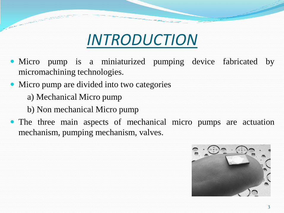
INTRODUCTION Micro pump is a miniaturized pumping device fabricated by
micromachining technologies.
Micro pump are divided into two categories
a) Mechanical Micro pump
b) Non mechanical Micro pump
The three main aspects of mechanical micro pumps are actuation
mechanism, pumping mechanism, valves.
3
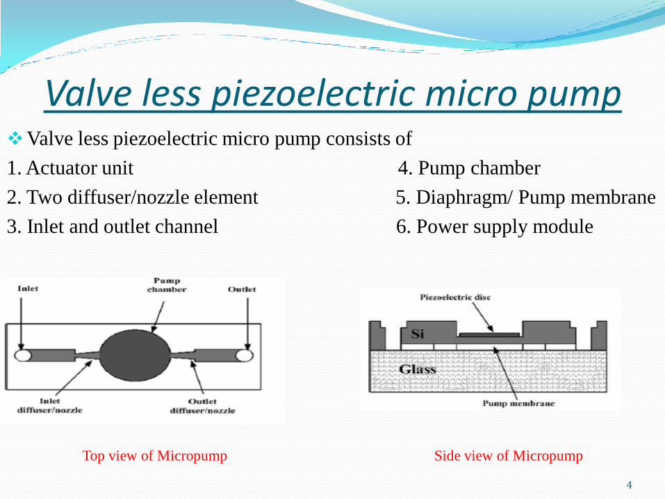
Valve less piezoelectric micro pump Valve less piezoelectric micro pump consists of
1. Actuator unit 4. Pump chamber
2. Two diffuser/nozzle element 5. Diaphragm/ Pump membrane
3. Inlet and outlet channel 6. Power supply module
Top view of Micropump Side view of Micropump
4
ACTUATOR UNIT
Actuator is necessary to operate the diaphragm of the micropump.
The actuator is made of a piezoelectric disc with the dimension of Φ6mm × 0.15mm thick and a silicon membrane with the dimension of Φ6mm× 0.1mm thick.
Inlet & outlet channel
Two short brass pipes are fixed to the pump inlet & outlet cavity of micro pump
Pump chamber
Pump chamber made up of silicon & covered by glass substrate.
Diaphragm
The diaphragm closes the cavity of pump chamber and it is bonded with the centre disk of the actuator.
Circular diaphragm made up of silicon 0.1mm thickness & 6mm diameter is chosen.
5
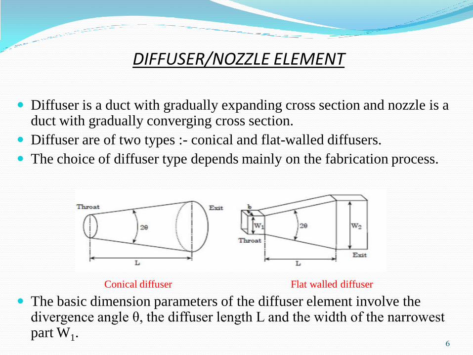
DIFFUSER/NOZZLE ELEMENT
Diffuser is a duct with gradually expanding cross section and nozzle is a
duct with gradually converging cross section.
Diffuser are of two types :- conical and flat-walled diffusers.
The choice of diffuser type depends mainly on the fabrication process.
Conical diffuser Flat walled diffuser
The basic dimension parameters of the diffuser element involve the divergence angle θ, the diffuser length L and the width of the narrowest part W1.
6
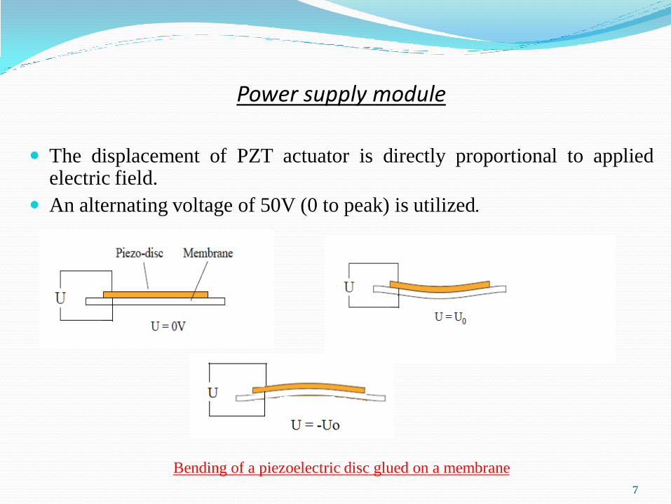
Power supply module
The displacement of PZT actuator is directly proportional to applied
electric field.
An alternating voltage of 50V (0 to peak) is utilized.
Bending of a piezoelectric disc glued on a membrane
7
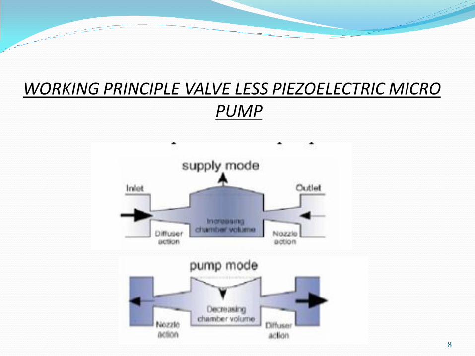
WORKING PRINCIPLE VALVE LESS PIEZOELECTRIC MICRO PUMP
8
SIMULATION RESULTS Simulations are carried out for two couplings in the micropump
design:-
The electromechanical coupling of piezoelectric actuator.
The fluid-structure coupling between the fluid and walls of
Nozzle/diffuser elements.
9
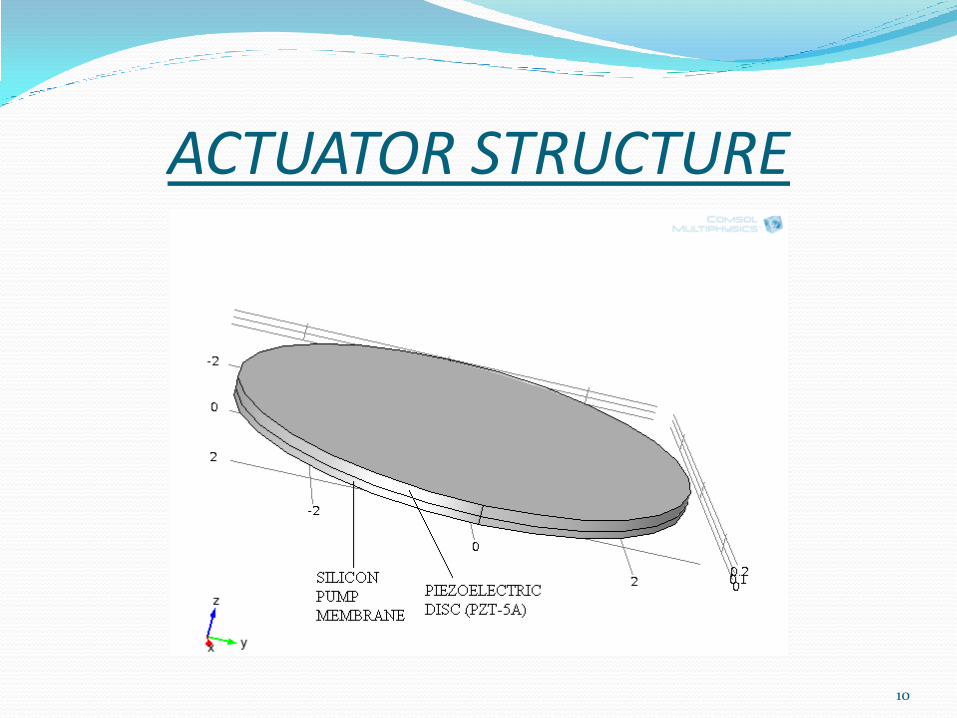
ACTUATOR STRUCTURE
10
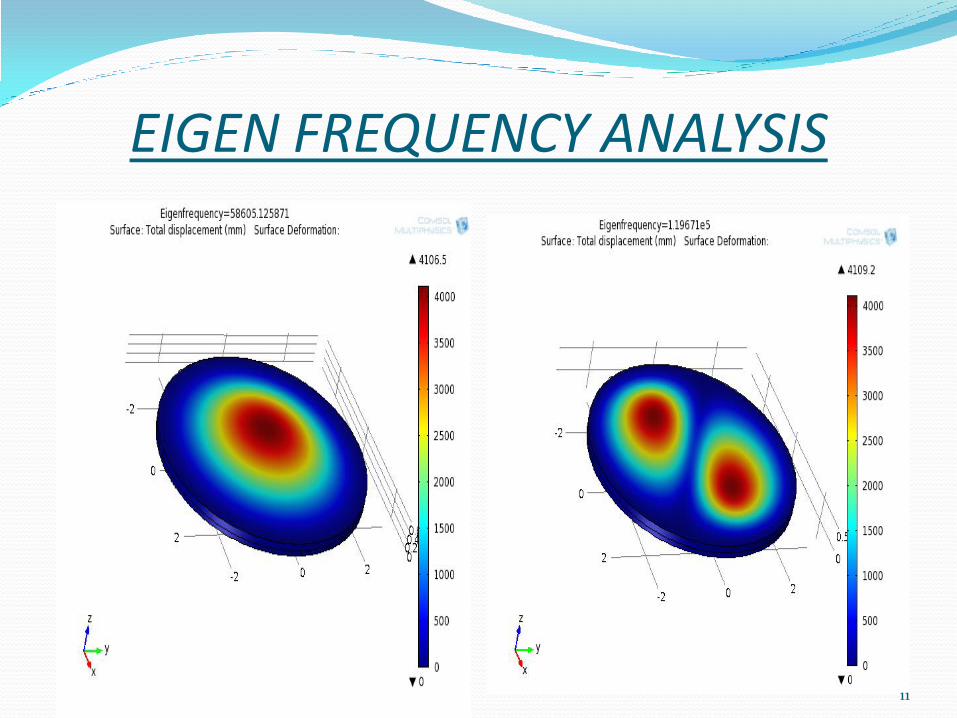
EIGEN FREQUENCY ANALYSIS
11
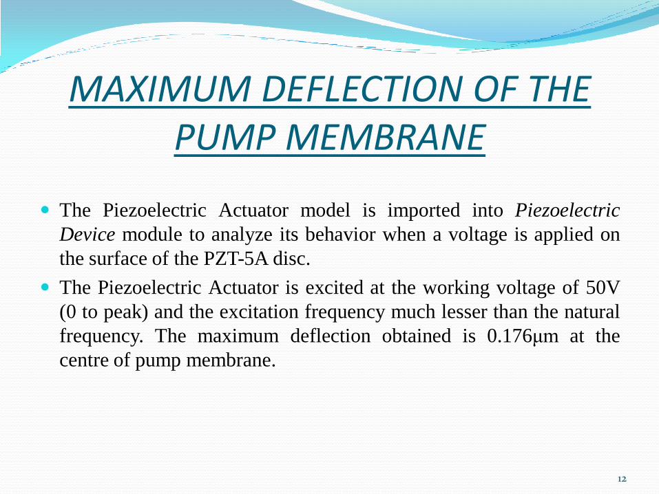
MAXIMUM DEFLECTION OF THE PUMP MEMBRANE
The Piezoelectric Actuator model is imported into Piezoelectric
Device module to analyze its behavior when a voltage is applied on
the surface of the PZT-5A disc.
The Piezoelectric Actuator is excited at the working voltage of 50V
(0 to peak) and the excitation frequency much lesser than the natural
frequency. The maximum deflection obtained is 0.176μm at the
centre of pump membrane.
12
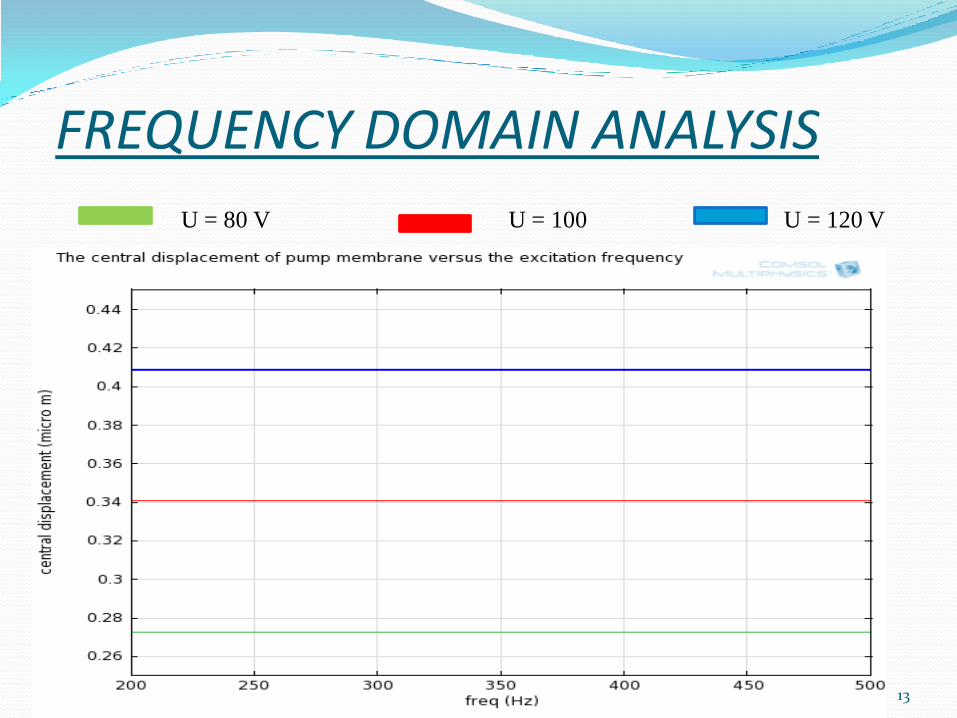
FREQUENCY DOMAIN ANALYSIS
U = 80 V U = 100 U = 120 V
13
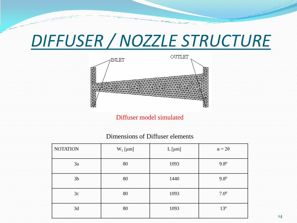
DIFFUSER / NOZZLE STRUCTURE
Diffuser model simulated
Dimensions of Diffuser elements
NOTATION W1 [μm] L [μm] α = 2θ
3a 80 1093 9.80
3b 80 1440 9.80
3c 80 1093 7.00
3d 80 1093 130
14
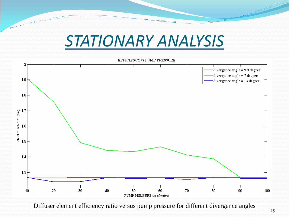
STATIONARY ANALYSIS
Diffuser element efficiency ratio versus pump pressure for different divergence angles 15
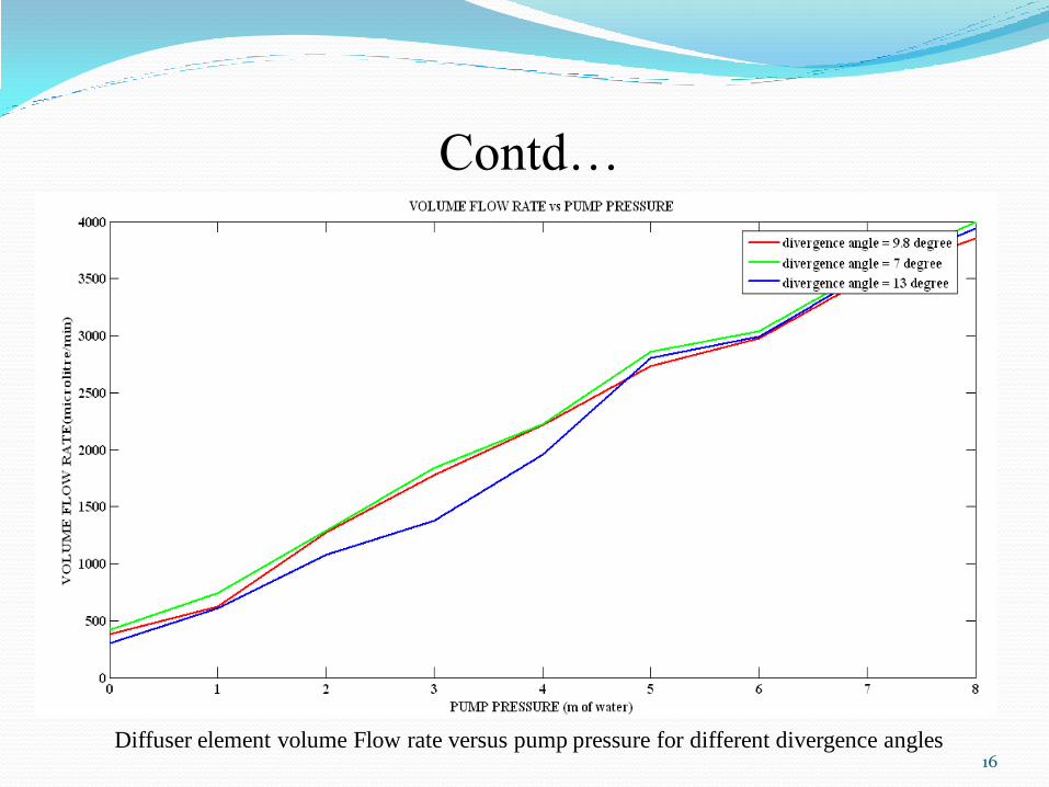
Contd…
Diffuser element volume Flow rate versus pump pressure for different divergence angles
16
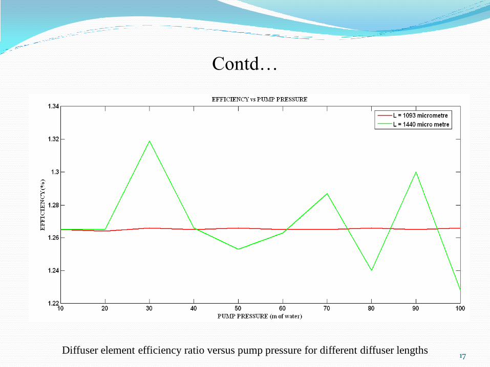
Contd…
Diffuser element efficiency ratio versus pump pressure for different diffuser lengths 17
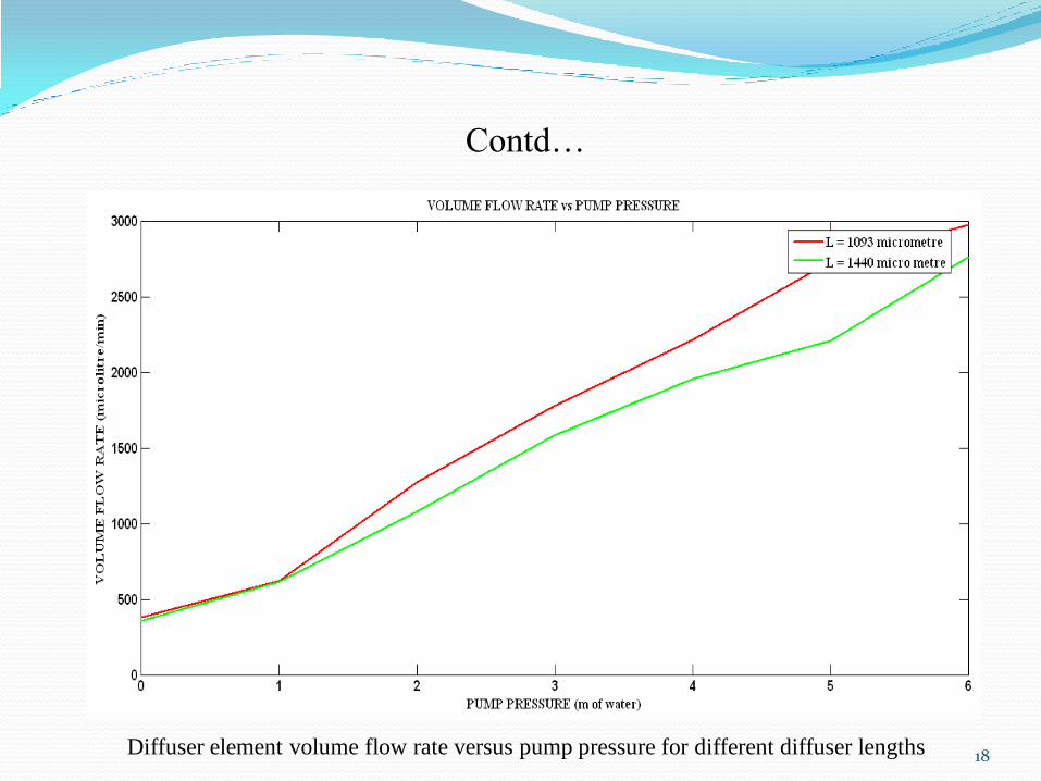
Contd…
Diffuser element volume flow rate versus pump pressure for different diffuser lengths 18
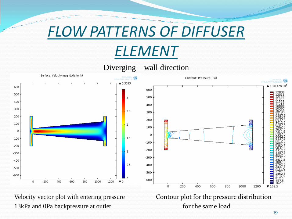
FLOW PATTERNS OF DIFFUSER ELEMENT
Diverging – wall direction
Velocity vector plot with entering pressure Contour plot for the pressure distribution
13kPa and 0Pa backpressure at outlet for the same load
19
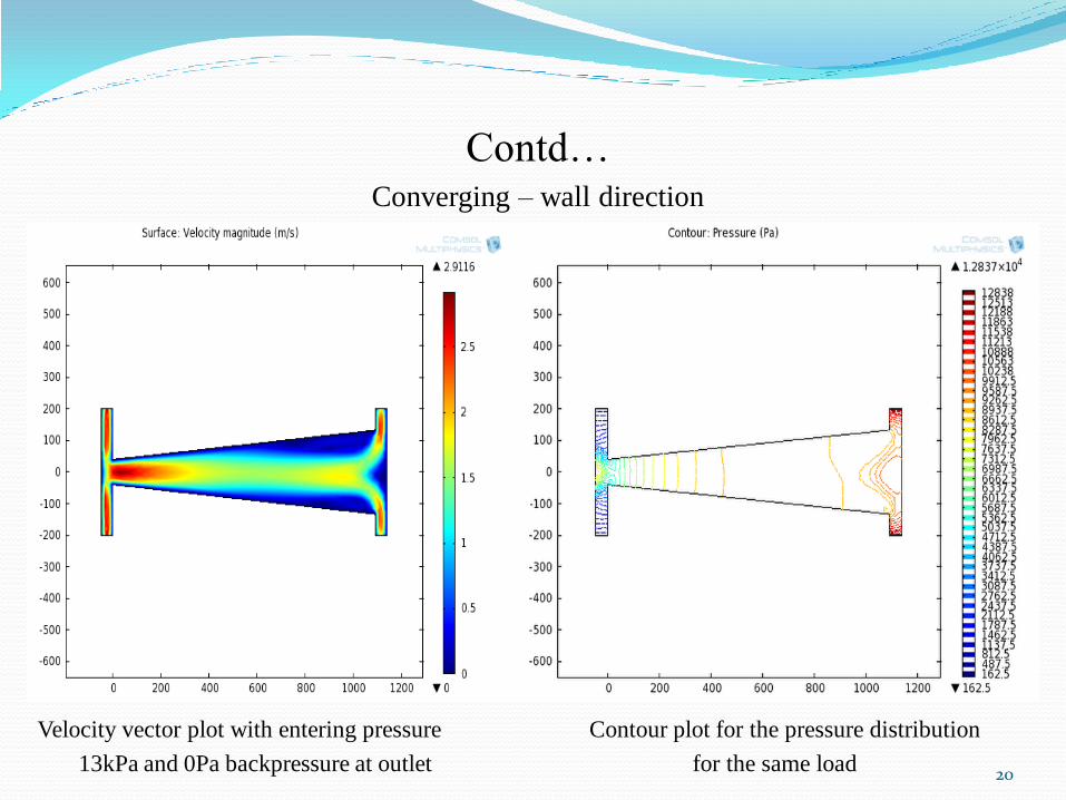
Contd… Converging – wall direction
Velocity vector plot with entering pressure Contour plot for the pressure distribution
13kPa and 0Pa backpressure at outlet for the same load
20
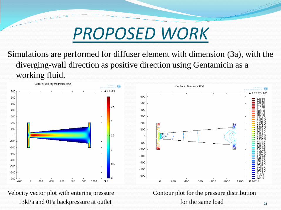
PROPOSED WORK Simulations are performed for diffuser element with dimension (3a), with the
diverging-wall direction as positive direction using Gentamicin as a
working fluid.
Velocity vector plot with entering pressure Contour plot for the pressure distribution
13kPa and 0Pa backpressure at outlet for the same load
21
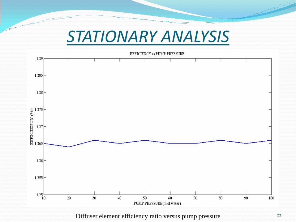
STATIONARY ANALYSIS
Diffuser element efficiency ratio versus pump pressure 22
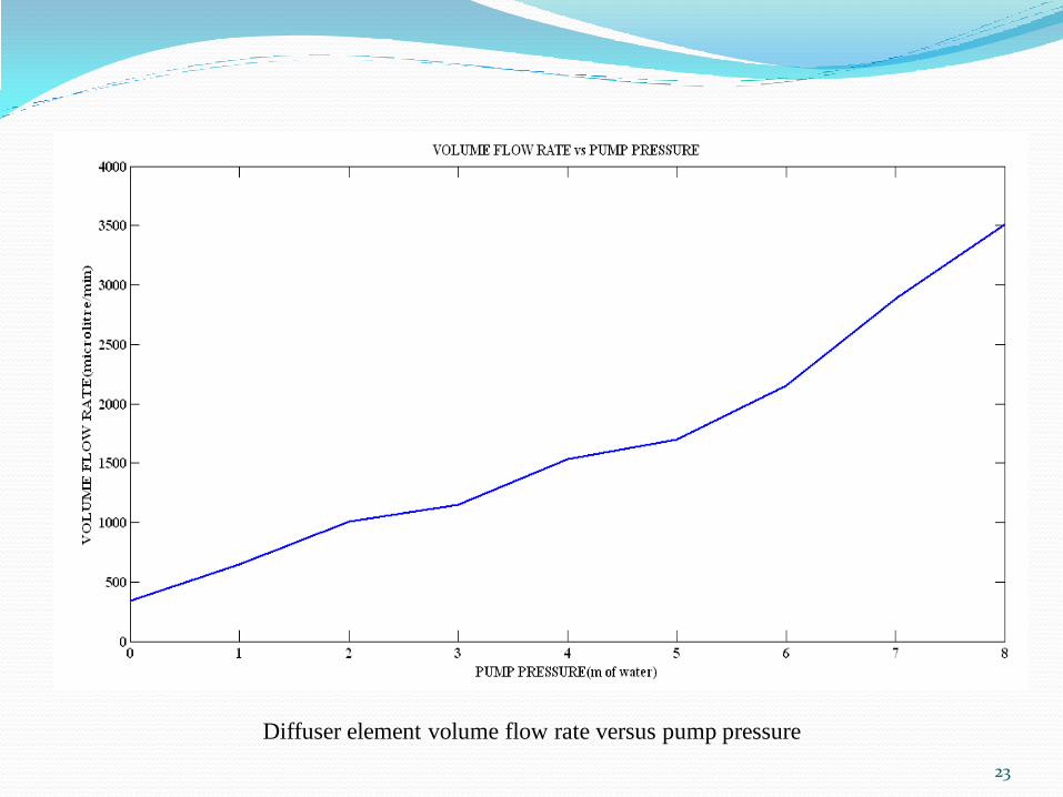
Diffuser element volume flow rate versus pump pressure
23
CONCLUSIONS AND SCOPE FOR FUTURE WORK
The simulation was performed for 3D membrane using Comsol package
and results conclude that deflection of actuator is linear with applied
potential over PZT material of the membrane.
On the other hand a 2D diffuser/nozzle element for gentamicin
intravenous administration was simulated for the laminar flow to check
the rate of change of flow from expansion towards the contraction and
vice versa.
24

ACKNOWLEDGMENT I take this opportunity to express my gratitude to
Dr. Premila Manohar, Professor, Head of Department, Dept of Electrical
& Electronics, MSRIT, Bengaluru.
Ms Supriya Babu, Assistant Professor, Department of Medical
Electronics, MSRIT, Bengaluru.
Dr. Manoj Govindarajuluyogish, Assistant Professor, Dept of
Pharmacology, MSRMC, Bengaluru.
COMSOL India.
25
REFERENCES [1] J.G. Smits; MESA; “Piezoelectric micropump for peristaltic fluid
displacement”; 1983 Patent NL 8302860
[2] H. van Lintel, F.C. M. VAN DE POL, S. BOUWSTRA “piezoelectric
micropump based on micromachining of silicon”; 1988
[3] G. Stemme ,KTH; Stockholm, “A novel piezoelectric valve-less fluid
pump” 1993.
[4] Anders Olsson, Goran Stemme, Erik Stemme, “A valve-less planar fluid
pump with two pump chambers” 1995.
[5] Qifeng Cui, Chengliang Liu, Xuan F, Zha, “Study on a piezoelectric
micropump for the controlled drug delivery system”; 2007
26

27