Design and Simulation of Implantable PIFA in Presence of ... · PDF fileDesign and Simulation...
11
www.ozeninc.com Page | 1 OZEN ENGINEERING, INC. 1210 E. Arques Ave. Suite: 207 Sunnyvale, CA 94085 PHONE: (408) 732-4665 www.ozeninc.com Design and Simulation of Implantable PIFA in Presence of ANSYS Human Body Model for Biomedical Telemetry Using ANSYS HFSS By Mehrnoosh Khabiri Abstract_ In this white paper, a small implantable Planar Inverted F Antenna (PIFA) is presented for Medical Implant Communications Service (MICS) band (402-405MHz). Design modification and tuning of antenna performance are studied when the implantable antenna is placed inside the skin tissue of ANSYS human body model. The resonance, radiation, and Specific Absorption Rate (SAR) of implantable PIFA are evaluated. Simulations are performed by ANSYS HFSS (High-Frequency Structural Simulator) which is based on Finite Element Method (FEM). I. Introduction In recent years, with rapid development of wireless communication technology, Wireless Body Area Networks (WBAN) have drawn a great attention. WBAN technology links electronic devices on and in the human body with exterior monitoring or controlling equipment. The common applications for WBAN technology are biomedical devices, sport and fitness monitoring, body sensors, mobile devices, and so on. All of these applications have been categorized in two main areas, namely medical and non-medical, by IEEE 802.15.6 standard [1]. For medical applications, the wireless telemetric links are needed to transmit the diagnostic, therapy, and vital information to the outside of human body [2], [3]. The wide and fast growing application of wireless devices yields to a lot of concerns about their safety standards related to electromagnetic radiation effects on human body. Interaction between human body tissues and Radio Frequency (RF) fields are important. Many researches have been done to investigate the effects of electromagnetic radiation on human body [4]-[7]. The SAR, which measures the electromagnetic power density absorbed by the human body tissue, is considered as an index by standards to regulate the amount of exposure of the human body to electromagnetic radiation [8], [9]. The implantable antennas are used for communication purposes in medical devices. Designing antennas for implanted devices is an extremely challenging task. The antennas require to be small, low profile, and multiband. Additionally, antennas need to operate in complex environments. Factors such as small size, low power requirement, and impedance matching play significant role in the design procedure. Although several antennas have been proposed for implantable medical devices [10]-[14], the accurate full human body model has been rarely included in the simulations. In this white paper, an implantable PIFA is proposed based on the design in [15] for communication between implanted medical devices in human body and outside medical equipment. Since the MICS band of 402-405 MHz is a common wireless telemetry for implantable medical devices [16], the proposed PIFA is designed for MICS band in this paper. The main aim of this work is to optimize the proposed implanted antenna inside the skin tissue of ANSYS
Transcript of Design and Simulation of Implantable PIFA in Presence of ... · PDF fileDesign and Simulation...

www.ozeninc.com P a g e | 1
OZEN ENGINEERING, INC. 1210 E. Arques Ave. Suite: 207
Sunnyvale, CA 94085 PHONE: (408) 732-4665
www.ozeninc.com
***CONFIDENTIAL***
Design and Simulation of Implantable PIFA in Presence of ANSYS Human Body
Model for Biomedical Telemetry Using ANSYS HFSS
By Mehrnoosh Khabiri
Abstract_ In this white paper, a small implantable Planar Inverted F Antenna (PIFA) is presented for
Medical Implant Communications Service (MICS) band (402-405MHz). Design modification and tuning of
antenna performance are studied when the implantable antenna is placed inside the skin tissue of ANSYS
human body model. The resonance, radiation, and Specific Absorption Rate (SAR) of implantable PIFA are
evaluated. Simulations are performed by ANSYS HFSS (High-Frequency Structural Simulator) which is
based on Finite Element Method (FEM).
I. Introduction
In recent years, with rapid development of wireless communication technology, Wireless Body Area
Networks (WBAN) have drawn a great attention. WBAN technology links electronic devices on and in the
human body with exterior monitoring or controlling equipment. The common applications for WBAN
technology are biomedical devices, sport and fitness monitoring, body sensors, mobile devices, and so on.
All of these applications have been categorized in two main areas, namely medical and non-medical, by
IEEE 802.15.6 standard [1]. For medical applications, the wireless telemetric links are needed to transmit
the diagnostic, therapy, and vital information to the outside of human body [2], [3]. The wide and fast
growing application of wireless devices yields to a lot of concerns about their safety standards related to
electromagnetic radiation effects on human body. Interaction between human body tissues and Radio
Frequency (RF) fields are important. Many researches have been done to investigate the effects of
electromagnetic radiation on human body [4]-[7]. The SAR, which measures the electromagnetic power
density absorbed by the human body tissue, is considered as an index by standards to regulate the amount
of exposure of the human body to electromagnetic radiation [8], [9].
The implantable antennas are used for communication purposes in medical devices. Designing
antennas for implanted devices is an extremely challenging task. The antennas require to be small, low
profile, and multiband. Additionally, antennas need to operate in complex environments. Factors such as
small size, low power requirement, and impedance matching play significant role in the design procedure.
Although several antennas have been proposed for implantable medical devices [10]-[14], the accurate
full human body model has been rarely included in the simulations. In this white paper, an implantable
PIFA is proposed based on the design in [15] for communication between implanted medical devices in
human body and outside medical equipment. Since the MICS band of 402-405 MHz is a common wireless
telemetry for implantable medical devices [16], the proposed PIFA is designed for MICS band in this paper.
The main aim of this work is to optimize the proposed implanted antenna inside the skin tissue of ANSYS

www.ozeninc.com P a g e | 2
OZEN ENGINEERING, INC. 1210 E. Arques Ave. Suite: 207
Sunnyvale, CA 94085 PHONE: (408) 732-4665
www.ozeninc.com
***CONFIDENTIAL***
human body model and characterize the electromagnetic radiation effects on human body tissues as well
as the SAR distribution. Simulations have been performed using ANSYS HFSS along with ANSYS Optimetrics
and High-Performance Computing (HPC) features.
This white paper is organized as follows. In section II, ANSYS human body model is presented.
Section III describes the antenna design. The simulation results such as reflection coefficient, SAR, near-
field and far-field are illustrated in Section IV. Finally, the conclusion is remarked in Section V.
II. ANSYS Human Body Model
ANSYS offers the adult-male and adult-female body models in several geometrical accuracy in
millimeter scale [17]. Fig. 1 shows a general view of the models. ANSYS human body model contains over
300 muscles, organs, tissues, and bones. The objects of the model have geometrical accuracy of 1-2 mm.
The human body materials are Frequency-dependent from 10 Hz to 10 GHz. Frequency-dependent
material properties are included in the ANSYS material Library. The data of material properties are based
on the research performed by [18]. The model can be modified by users for the specific applications and
parts, and model objects can simply be removed if not needed. For high frequencies, the body model can
be electrically large, resulting in huge number of meshes which makes the simulation very time-consuming
and computationally complex. The ANSYS HPC technology enables parallel processing, such that one has
the ability to model and simulate very large size and detailed geometries with complex physics.
Fig. 1 ANSYS Human Body Models [17]

www.ozeninc.com P a g e | 3
OZEN ENGINEERING, INC. 1210 E. Arques Ave. Suite: 207
Sunnyvale, CA 94085 PHONE: (408) 732-4665
www.ozeninc.com
***CONFIDENTIAL***
In presented work, the implantable antenna is placed inside the skin tissue of the left upper chest
where most pacemakers and implanted cardiac defibrillators are located [3]. Incorporating ANSYS
Optimetrics and HPC features, optimization iterations can be performed in an efficient manner to simulate
the implantable antenna inside the human body model.
III. Antenna Design
The general shape of proposed PIFA is based on the presented work in [15]. The antenna is
simulated in the ANSYS HFSS which is a FEM electromagnetic solver. In the simulations, Rogers RO3210
(εr=10.2 and tanδ=0.003) is used as the substrate and superstrate material. Top and side view of proposed
PIFA is illustrated in Fig. 2. The origin of the coordinate system is located in the center of the Antenna’s
ground plane. The thickness of dielectric layer of both substrate and superstrate is 1.28 mm. The length
and width of the substrate and superstrate are Lsub=20mm and Wsub=24mm, respectively. The width of
each radiating strip is Wstrip=3.8mm. The other parameters of antenna are considered to be changed
within the solution space in order to improve PIFA performance at 402 MHz center frequency. HFSS
Optimetrics, an integrated tool in HFSS for parametric sweeps and optimizations, is used for tuning and
improving the antenna characteristics at the MICS bands inside the ANSYS human body model. A
grounding pin is used at the end of the radiating strip to achieve smaller antenna size. The location of the
feed can be optimized along x- and y-axis to match the antenna to 50Ω over MISC band. The strip lengths
(Lstrip1 and Lstrip4) are also included in optimizations to provide more degrees of freedom for improving the
PIFA performance at the desired frequency band (402-405 MHz). The 3D view of the implantable PIFA is
demonstrated in Fig. 3.
Fig. 2 Top and side view of PIFA

www.ozeninc.com P a g e | 4
OZEN ENGINEERING, INC. 1210 E. Arques Ave. Suite: 207
Sunnyvale, CA 94085 PHONE: (408) 732-4665
www.ozeninc.com
***CONFIDENTIAL***
Fig. 3 3D view of PIFA geometry in HFSS
The antenna is designed and simulated while implanted inside the skin tissue of the left upper chest
of the detailed male body model, as shown in Fig. 4.
Fig. 4 Implanted antenna in ANSYS male human body model
IV. Results and Analysis
The reflection coefficient (S11) frequency response of the implanted PIFA is presented in Fig. 5. The
antenna resonates at 402 MHz with -28 dB reflection coefficient and provides 36 MHz bandwidth covering
the MICS band. The simulated input impedance (Zin) frequency response is shown in Fig. 6. As can be seen,
the proposed PIFA is matched at 402 MHz.

www.ozeninc.com P a g e | 5
OZEN ENGINEERING, INC. 1210 E. Arques Ave. Suite: 207
Sunnyvale, CA 94085 PHONE: (408) 732-4665
www.ozeninc.com
***CONFIDENTIAL***
Fig. 5 Reflection coefficient of implanted PIFA inside the skin tissue of human body model
Fig. 6 Input Impedance of implanted PIFA inside the skin tissue of human body model
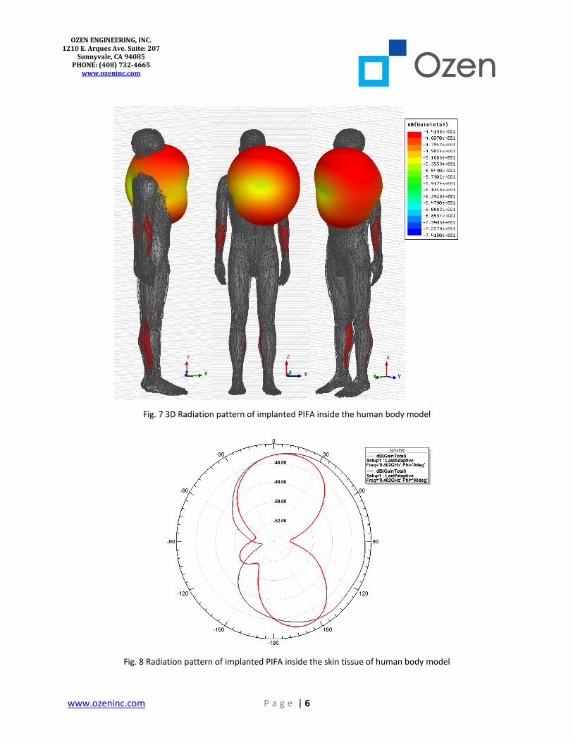
The Fig. 7 and Fig. 8 illustrate the far-field radiation pattern of the proposed PIFA at 402 MHz. Since
the antenna is electrically small and the human body provides a lossy environment, the antenna gain is
very small (~-44 dBi) and the EM fields are reactively stored in the human body parts in vicinity.
www.ozeninc.com P a g e | 6
OZEN ENGINEERING, INC. 1210 E. Arques Ave. Suite: 207
Sunnyvale, CA 94085 PHONE: (408) 732-4665
www.ozeninc.com
***CONFIDENTIAL***
Fig. 7 3D Radiation pattern of implanted PIFA inside the human body model
Fig. 8 Radiation pattern of implanted PIFA inside the skin tissue of human body model

www.ozeninc.com P a g e | 7
OZEN ENGINEERING, INC. 1210 E. Arques Ave. Suite: 207
Sunnyvale, CA 94085 PHONE: (408) 732-4665
www.ozeninc.com
***CONFIDENTIAL***
Fig. 9 shows the simulated electric field distributions around the male human body model at 402
MHz center frequency. The electric field magnitude is large at upper side of the body, and it becomes
weaker as going far away from the male body chest.
Fig. 9 Electric Field distribution around male body model at 402 MHz
The reflection coefficients are plotted for various lengths of radiating strip in Fig. 10. With HFSS
Optimetrics, the radiating strip length is varied to optimize PIFA performance at 402 MHz. The variation
of Lstrip1 and Lstrip4 are observed to be critical for changing the resonance frequency of PIFA. As can be seen,
the resonance frequency is shifted upward by decreasing the Lstrip1 and Lstrip4. The optimization results
indicate that the Lstrip1=11.25mm and Lstrip4=8.5mm are the optimized values for antenna performance at
MICS band.
The electromagnetic power absorbed by tissues surrounding the antenna inside the human body
model is a critical parameter. Hence, SAR analysis is required to evaluate the antenna performance. The
SAR measurement makes it possible to evaluate if a wireless medical device satisfies the safety limits. The
SAR is calculated as:

www.ozeninc.com P a g e | 8
OZEN ENGINEERING, INC. 1210 E. Arques Ave. Suite: 207
Sunnyvale, CA 94085 PHONE: (408) 732-4665
www.ozeninc.com
***CONFIDENTIAL***
𝑆𝐴𝑅 = ∫𝜎(𝑟)|𝐸(𝑟)|2
𝜌(𝑟)
𝑠𝑎𝑚𝑝𝑙𝑒
𝑑𝑟
where E is the root mean square (rms) electric field strength, σ is the electrical conductivity, and ρ is the
mass density of the tissue sample.
The unit of SAR is watt per kilogram (W/kg). The SAR is averaged either over the whole body or a small
volume (typically 1 g or 10 g of tissue). The IEEE standard limits the 10 grams averaged SAR value to 2W/kg
while the Federal Communications Commission (FCC) uses the 1 gram averaged SAR value to 1.6 W/kg
[8], [19]. The whole body SAR value is limited to 0.08 W/kg by both IEEE and FCC. The FCC limits the
Effective Radiated Power (ERP) of such devices to 25 µw outside of human body. ANSYS HFSS offers SAR
calculations according to these standards. The 3D plots of the local SAR distribution are shown in Fig.11
and Fig. 12. In Fig. 11, the detailed male body model with heart, lungs, liver, stomach, intestines, and brain
are included. It can be observed that the left upper chest region where SAR is significant is relatively small.
The peak SAR of the PIFA is smaller than the regulated SAR limitation. Fig. 12 shows the SAR distribution
on the skin tissue of the full human body model for MICS band.
Fig. 10 Reflection coefficient of implanted PIFA inside the skin tissue of the human body model for different lengths
of radiating strips

www.ozeninc.com P a g e | 9
OZEN ENGINEERING, INC. 1210 E. Arques Ave. Suite: 207
Sunnyvale, CA 94085 PHONE: (408) 732-4665
www.ozeninc.com
***CONFIDENTIAL***
Fig. 11 Local SAR distribution on upper side of male body model at 402 MHz
Fig. 12 Local SAR distribution on the skin tissue of male body model at 402 MHz

www.ozeninc.com P a g e | 10
OZEN ENGINEERING, INC. 1210 E. Arques Ave. Suite: 207
Sunnyvale, CA 94085 PHONE: (408) 732-4665
www.ozeninc.com
***CONFIDENTIAL***
V. Conclusion
In this study, we presented an implanted PIFA inside skin tissue of human body model for
biomedical telemetry at MICS band. The design and simulation of the antenna were performed using
ANSYS HFSS FEM electromagnetic solver. The Optimetrics feature of ANSYS HFSS was employed to
optimize the antenna performance at 402 MHz. The optimization results demonstrate that the length
variation of the radiating strip affects the resonance frequency significantly. The resonance frequency,
reflection coefficient, input impedance, radiation characteristic, and SAR of the implanted antenna were
evaluated. The SAR analysis inside human body model was performed to meet the standard requirements.
For sake of more investigations, an extensive antenna optimization could be performed to obtain
miniaturized antenna size and improved antenna performance for implantable medical devices.
Furthermore, the effect of implanted antenna placement in different location of human body model could
be investigated to satisfy safety limits for wireless medical devices.
References
[1] IEEE 802.15.6 for Wireless Personal Area Networks, http://www.ieee802.org/15/
[2] B. M. Steinhaus, et al., “The role of telecommunications in future implantable device systems,” Proc. 16th IEEE EMBS Conf., Baltimore, MD, pp. 1013-1014, 1994.
[3] J. Kim and Y. Rahmat-Samii, “Implanted antennas inside a human body: simulations, designs and characterizations,” IEEE Trans. Microw. Theory Tech., vol. 52, pp. 1934–1943, Aug. 2004.
[4] D. Wessels, “Implantable pacemakers and defibrillators: device overview and EMI considerations,” IEEE Electromagnetic Compatibility Int. Symp., vol. 2, pp. 911-915, 2002
[5] P. J. Dimbylow, “Fine resolution calculations of SAR in the human body for frequencies up to 3GHz,” Phys. Med. Bio., vol. 47, no. 16, pp. 2835–2846, 2002.
[6] L. Xu, M. Q. H. Meng, H. Ren, and Y. Chan, “Radiation characteristics of ingestible wireless devices in human intestine following radio frequency exposure at 430, 800, 1200, and 2400 MHz,” IEEE Trans. Antennas Propagation, vol. 57, no. 8, pp. 2418–2428, Aug. 2009.
[7] M. Klemm and G. Troester, “EM energy absorption in the human body tissues due to UWB antennas,” Progress Electromagnetic Research, vol. 62, pp. 261–280, 2006.
[8] IEEE Standard for Safety Levels With Respect to Human Exposure to Radio Frequency Electromagnetic Fields, 3 kHz to 300 GHz IEEE, IEEE Standard C95.1-2005, 2005.
[9] “Guidelines for limiting to time varying electric, magnetic, and electromagnetic fields (up to 300 GHz),” ICNIRP, Oberschleissheim, Germany, 1997.
[10] Kim, J. and Y. Rahmat-Samii, “Implanted antennas inside a human body: Simulations, designs, and characterizations,” IEEE Trans. Microw. Theory Tech., Vol. 52, No. 8, 1934-1943, Aug. 2004.

www.ozeninc.com P a g e | 11
OZEN ENGINEERING, INC. 1210 E. Arques Ave. Suite: 207
Sunnyvale, CA 94085 PHONE: (408) 732-4665
www.ozeninc.com
***CONFIDENTIAL***
[11] Warty, R. and M. R. Tofighi, “Characterization of implantable antennas for intracranial pressure monitoring: Reflection by and transmission through a scalp phantom,” IEEE Trans. Microw. Theory Tech., Vol. 56, No. 10, Oct. 2008.
[12] Karacolak, T., A. Z. Hood, and E. Topsakal, “Design of a dual-band implantable antenna and development of skin mimicking gels for continuous glucose monitoring,” IEEE Trans. Microw. Theory Tech., Vol. 56, No. 4, 1001-1008, Apr. 2008.
[13] W. C. Liu, S. H. Chen, and C. M. Wu, “Implantable broadband circular stacked PIFA antenna for biotelemetry communication,” J. of Electromagnetic Waves and Appl., vol. 22, pp. 1791–1800, 2008.
[14] W. C. Liu, S. H. Chen, and C. M. Wu, “Bandwidth enhancement and size reduction of an implantable PIFA antenna for biotelemetry devices,” Microw. Opt. Technol. Lett., vol. 51, pp. 755–757, Mar. 2009.
[15] Y. Rahmat-Samii and J. Kim, “Implanted Antennas in Medical Wireless Communications”, 1st ed. Morgan & Claypool Publishers, 2006.
[16] Medical implant communications service (MICS) federal register, Rules Reg., vol. 64, no. 240, pp. 69926–69934, Dec. 1999.
[17] Martin Vogel, “Electromagnetic Safety in Wireless Communications and Bio-Medical Technologies”, ANSYS white paper, ANSYS Inc., 2014.
[18] C. Gabriel "Compilation of the dielectric properties of body tissues at RF and microwave frequencies", Report N.AL/OE-TR- 1996-0037, Occupational and environmental health directorate, Radiofrequency Radiation Division, Brooks Air Force Base, Texas (USA), June 1996.
[19] FCC guidelines for evaluating the environmental effects of radio frequency radiation, FCC, Washington, DC, 1996.