Design and simulation hybrid filter for 17 level ...
12
Bulletin of Electrical Engineering and Informatics Vol. 9, No. 3, June 2020, pp. 886~897 ISSN: 2302-9285, DOI: 10.11591/eei.v9i3.890 886 Journal homepage: http://beei.org Design and simulation hybrid filter for 17 level multilevel inverter Marshal Andrea Hutabarat, Syafruddin Hasan, Ali Hanafiah Rambe, Suherman Electrical Enginering Department, Universitas Sumatera Utara, Indonesia Article Info ABSTRACT Article history: Received Jan 11, 2018 Revised Oct 24, 2019 Accepted Jan 10, 2020 The increasing of renewable energy applications such as solar cells, wind power, ocean thermal and HVDC (high voltage direct current) cause increment in the use of the inverter circuit. Harmonics that are generated by the inverter have negative impacts on the electrical equipment; harmonics cause excessive heat and may shorten the life of electrical equipment. A multilevel inverter is an arranged of cascaded inverters which aims to reduce total harmonic distortion (THD). This paper proposes the design of 17 levels of a single-phase cascaded multilevel inverter with a hybrid filter insertion. By using PSIM simulator, the hybrid filter is proven reducing THD better than single pulse width modulation (SPWM) inverter. Installation of the hybrid filter is able to fix a maximum of 0.23% THDv and a maximum of 1.05% THDi. Hybrid filter installation reduces the value of THD to comply with IEEE 519-2014 standard. Keywords: Cascaded multilevel inverter Hybrid filter SPWM inverter THD This is an open access article under the CC BY-SA license. Corresponding Author: Marshal Andrea Hutabarat, Department of Electrical and Computer Engineering, University of North Sumatera, Abdul Hakim St. No.1, Padang Bulan, Kec. Medan Baru, Kota Medan, Sumatera Utara 20222, Indonesia. Email: [email protected] m 1. INTRODUCTION Population increases every year. This growth is directly proportional to the need for electrical energy, which is also growing [1]. As energy sources are limited, the use of renewable energy becomes an alternative to satisfy the need for electrical energy. Since electrical waveform generated by renewable sources such as solar cells is dominated by direct current (DC), the used of inverter becomes frequent to convert DC Voltage to AC Voltage. Such devices have been widely available in the market and have been used for many applications [2]. However, the AC waveform generated by the inverters is often costly, poor quality output and containing high harmonic indices [3]. Many researchers have done real works in designing inverter. For instance, Arif et al [4] focused on the multi-level topology, while Jidin et al [5] used space vector modulation to improve the output voltage. Another researcher [6] reduced the total harmonics distortion (THD) by adjusting the inverter itself. Therefore, this paper focuses on the use of filters in inverter. This paper proposes a hybrid filter insertion on the output of the inverter. It is expected by doing so, THD complies with the IEEE 519-2014 standard requirement [7]. The proposed filter is a hybrid filter, which is a combination of two filters: an active filter and a passive filter [8, 9]. Hybrid filters have more benefits than passive filters in filtering harmonics, both from the viewpoint of usefulness and performance, particularly for extraordinary power applications [10, 11]. The active filter is delineated by performing similar to resistors during harmonic frequencies, resulting in harmonic elimination across distribution channels [12]. The active filter works by injecting harmonic current into the circuit so the inverter can work under different load conditions. It is applied to
Transcript of Design and simulation hybrid filter for 17 level ...
Bulletin of Electrical Engineering and Informatics
Vol. 9, No. 3, June 2020, pp. 886~897
ISSN: 2302-9285, DOI: 10.11591/eei.v9i3.890 886
Journal homepage: http://beei.org
Design and simulation hybrid filter for 17 level
multilevel inverter
Marshal Andrea Hutabarat, Syafruddin Hasan, Ali Hanafiah Rambe, Suherman Electrical Enginering Department, Universitas Sumatera Utara, Indonesia
Article Info ABSTRACT
Article history:
Received Jan 11, 2018
Revised Oct 24, 2019
Accepted Jan 10, 2020
The increasing of renewable energy applications such as solar cells,
wind power, ocean thermal and HVDC (high voltage direct current) cause
increment in the use of the inverter circuit. Harmonics that are generated
by the inverter have negative impacts on the electrical equipment; harmonics cause excessive heat and may shorten the life of electrical equipment.
A multilevel inverter is an arranged of cascaded inverters which aims
to reduce total harmonic distortion (THD). This paper proposes the design
of 17 levels of a single-phase cascaded multilevel inverter with a hybrid filter
insertion. By using PSIM simulator, the hybrid filter is proven reducing THD better than single pulse width modulation (SPWM) inverter. Installation
of the hybrid filter is able to fix a maximum of 0.23% THDv and a maximum
of 1.05% THDi. Hybrid filter installation reduces the value of THD
to comply with IEEE 519-2014 standard.
Keywords:
Cascaded multilevel inverter
Hybrid filter
SPWM inverter
THD
This is an open access article under the CC BY-SA license.
Corresponding Author:
Marshal Andrea Hutabarat,
Department of Electrical and Computer Engineering,
University of North Sumatera,
Abdul Hakim St. No.1, Padang Bulan, Kec. Medan Baru, Kota Medan, Sumatera Utara 20222, Indonesia.
Email: [email protected]
1. INTRODUCTION
Population increases every year. This growth is directly proportional to the need for electrical
energy, which is also growing [1]. As energy sources are limited, the use of renewable energy becomes an
alternative to satisfy the need for electrical energy. Since electrical waveform generated by renewable
sources such as solar cells is dominated by direct current (DC), the used of inverter becomes frequent to
convert DC Voltage to AC Voltage. Such devices have been widely available in the market and have bee n
used for many applications [2]. However, the AC waveform generated by the inverters is often costly, poor
quality output and containing high harmonic indices [3]. Many researchers have done real works in designing
inverter. For instance, Arif et al [4] focused on the multi-level topology, while Jidin et al [5] used space
vector modulation to improve the output voltage. Another researcher [6] reduced the total harmonics
distortion (THD) by adjusting the inverter itself. Therefore, this paper focuses on the use of filters in inverter.
This paper proposes a hybrid filter insertion on the output of the inverter. It is expected by doing so, THD
complies with the IEEE 519-2014 standard requirement [7]. The proposed filter is a hybrid filter, which is
a combination of two filters: an active filter and a passive filter [8, 9]. Hybrid filters have more benefits than
passive filters in filtering harmonics, both from the viewpoint of usefulness and performance, particularly for
extraordinary power applications [10, 11].
The active filter is delineated by performing similar to resistors during harmonic frequencies,
resulting in harmonic elimination across distribution channels [12]. The active filter works by injecting
harmonic current into the circuit so the inverter can work under different load conditions. It is applied to

Bulletin of Electr Eng & Inf ISSN: 2302-9285
Design and simulation hybrid filter for 17 level multilevel inverter (Marshal Andrea Hutabarat)
887
compensate voltage harmonic in series with active power filter or to compensate current harmonic in shunt
with active power filter [13, 14]. The active filter injects the compensation current into the circuit. Therefore,
the THDi in the circuit improves. The passive filter works on a particular tuned frequency so that harmonic
current is passed through a passive filter and the load receives voltage and current with muted harmonics.
The LCL filter is a popular solution for voltage source converter connected to the network for its
ability to achieve better harmonic switching mitigation [15-17]. Previously, the L filter was used to reduce
the harmonic content at high switching frequencies , by inserting it in between the grid source
and the converter’s poles [18, 19]. However, to meet the power quality standard, a significant value
of inductor is expected [20]. Thirumoorthi & Yadaiah state that LC filter is the simplest method to mitigate
the reactive power and harmonic current [21]. Nevertheless, its simple approach also has limitations [22].
Therefore, to gain maximum results, the LCL filter is installed as a passive filter in this work.
The IEEE 519-2014 allows the permitted THD level by a maximum value of 8%. THD level higher
than 8% may generate non-sinusoidal output that injects negative influences on the loads. High harmonic
values increase the temperature of electronic devices, which become rapidly hot. The manual pulse settings
cause unstable generated frequencies [23].
2. CASCADED MULTILEVEL INVERTER
The output voltage generated by the inverter is ideally sinuso idal [24]. However, in reality,
it contains harmonics that generate non-sinusoidal output waveform. The non-sinusoidal transients are still
acceptable for low and medium power applications. Nevertheless, minimal inverter requirements for
harmonics and sinusoidal voltages are needed for high power applications [25].
Figure 1 shows three different inverter output voltages: + VDC, 0 and –VDC. DC source
is connected to the AC output side by various combinations of four switches : S1, S2, S3, and S4.
For instance, by turning ON S1 and S4 yield + VDC, turning ON S2 and S3 yield –VDC and turning OFF all
switches yield 0 voltage. The output voltage is the sum of the voltages generated by each inverter level.
The output voltage level is 2n + 1, where n is the number of DC voltage sources.
(a) (b)
Figure 1. Cascaded multilevel inverter, (a) Inverter circuit, (b) Output waveform

ISSN: 2302-9285
Bulletin of Electr Eng & Inf, Vol. 9, No. 3, June 2020 : 886 – 897
888
Since the inverter has five DC sources, the output voltage level will be 11 levels of cascaded
multilevel inverter. The higher the levels, the better the quality of the output [26]. The first H-bridge
produces VDC1 Volt during time Ɵ1. The second H-bridge provides VDC2 Volt during time Ɵ2 and so on
until VDC5. The sum of the five inverter outputs synthesizes the phase output voltage,
VOut=VDC1+VDC2+VDC3+VDC4+VDC5, as expressed by (1) [1], where V(ωt) is the output voltage,
VDC is DC input voltage source and θ is IGBT turning point.
(1)
3. CIRCUIT DESIGN
3.1. Design 17 level cascaded multilevel inverter
The multilevel inverter cascaded circuit uses 8 H-bridge inverters. Each level works on 30 VDC
voltages. Each H-bridge inverter uses four pieces insulated gate bipolar transistors (IGBTs).
IGBT is a semiconductor component that is widely used as a switch that combines high-efficiency
switching [27]. IGBT is a transistor that designed with high impedance, so it does not overload the control
circuit, especially the driver part. Different from any previous power semiconductors, the ON and OFF
conditions of IGBT do not produce power losses.
The working pulse/angle setting of IGBT uses a pulse generator. In PSIM software simulator,
this setting is available by using a gating block for the switch. Gating block switch 1 (G1) is used for IGBT 1
and 4 drivers. Gating block switch 2 (G2) is used as IGBT 2 and IGBT 3. The G1 driver is set at the ignition
angle from 5o to 175o for positive pulses. G2 is set on the ignition angle from 185o to 355o for negative
pulses. Setup for all drivers is displayed in Table 1.
After adjusting all gating blocks as described in Table 1, the voltage probe is added to evaluate
the waveform generated by the cascaded multilevel inverter circuit. The whole circuit of the multilevel
cascaded inverter is shown in Figure 2. The designed circuit is assembled by 32 IGBTs, connected to 8
voltage source of 30 VDC. After simulation executed, the output voltage generated by this circuit and its
THD values are obtained. Figure 3 shows the waveforms and harmonics spectrum of the output voltage.
The effective root mean square (rms) value of the output voltage (Vrms) is 153.49 V and the total harmonic
distortion (THDv) produced by this circuit is 11.72%.
Table 1. Setting IGBT ignition angle Gating Block IGBT Ignition Angle (0)
G1 1 & 4 5-175
G2 2 & 3 185-355 G3 5 & 8 15-165 G4 6 & 7 195-345 G5 9 & 12 25-155
G6 10 & 11 205-335 G7 13 & 16 35-145 G8 14 & 15 215-325
G9 17 & 20 45-135 G10 18 & 19 225-315 G11 29 & 32 55-125 G12 30 & 31 235-305
G13 26 & 27 245-295 G14 25 & 28 65-115 G15 22 & 23 255-285 G16 21 & 24 75-105
3.2. Filter design
The source impedance strongly affect the filtering characteristics . It causes system resonance in
passive filter application. These drawbacks can be removed by introducing a combination of active
and passive power filters with appropriate coordination. The LCL passive filter is used in design due to its
high filtering performance. LCL filter minimizes cost, size and weight. Moreover, LCL filter is suitable to
meet harmonic constraints as defined by standard IEEE 519 [28]. The designed active filter control
is performed by using current sensors, summing amplifiers and invert ing amplifiers. The current sensor
detects the changing current and transmits its waveforms to the summing amplifier. The current waveform

Bulletin of Electr Eng & Inf ISSN: 2302-9285
Design and simulation hybrid filter for 17 level multilevel inverter (Marshal Andrea Hutabarat)
889
is a reference wave to be compared to the sine waveform generated by the oscillator. The comparison result
is the current waveform that is injected into the circuit as compensation.
The inverting amplifier circuit serves as a voltage inverter for the phase voltage generated by a sine
wave oscillator. This sine wave is 180o phase different from the sine wave generated by the oscillator.
The inverting amplifier circuit adjusts the IGBT startup angle and the summing amplifier circuit controls
the compensation current. The active filter used in this work is an active shunt filter. The topology is depicted
in Figure 4. Input filter is taken from the driver inverter, and the output filter is connected to the load.
The active shunt filter injects the compensation current into the circuit so that the THDi value in the injected
circuit improves.
Figure 2. The multilevel inverter simulation circuit
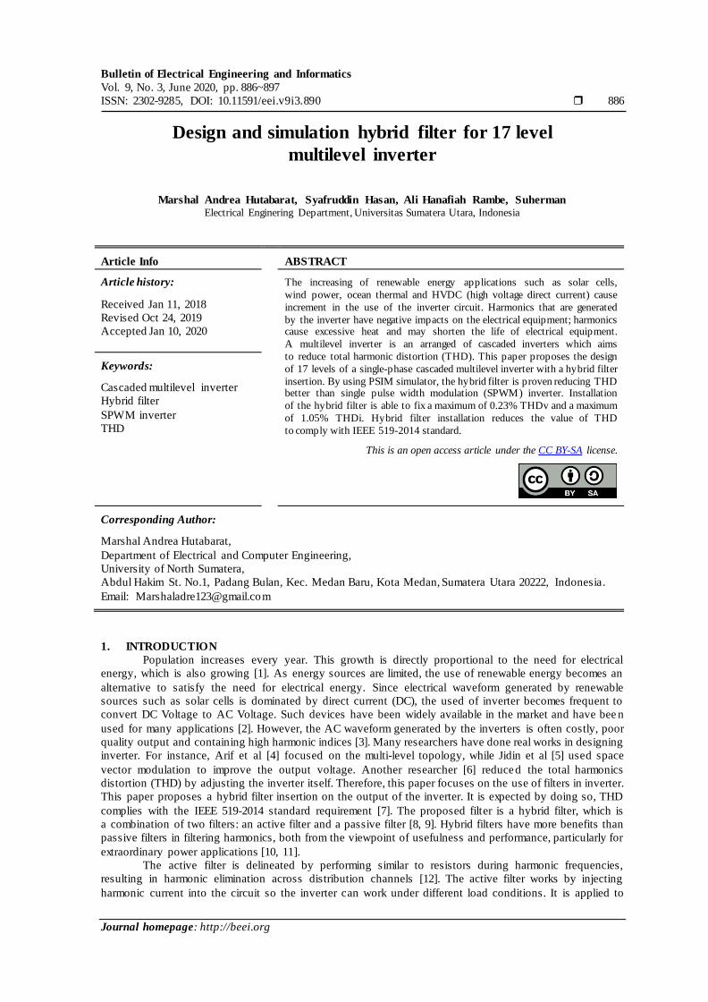
The active shunt filter uses a voltage source inverter (VSI) and the inverter type is the H-bridge
inverter. The H-bridge inverter is driven by the generated harmonics. The SPWM generator is used to ignite
the IGBTs. The single-phase full-bridge inverter is arrange in series of sinus generators (oscillators).
The output is then compared to the output waveform of the summing amplifier. Afterward, the current
injection flows through the Lf inductor. The driver and the compensation circuits are shown in Figure 5.
The LCL filter circuit design is shown in Figure 6. The value of C is determined based on values
0.0001F or 100μF. The cutoff frequency is determined 50 Hz as the power frequency of the intended
application. Then inductor value, L is determined by using (2) [1].

ISSN: 2302-9285
Bulletin of Electr Eng & Inf, Vol. 9, No. 3, June 2020 : 886 – 897
890
(2)
(a)
(b)
Figure 3. Output voltage waveform and its harmonic spectrum, (a) Voltage waveform,
(b) Harmonic spectrum
Figure 4. Block diagram of the active filter
Bulletin of Electr Eng & Inf ISSN: 2302-9285
Design and simulation hybrid filter for 17 level multilevel inverter (Marshal Andrea Hutabarat)
891
(a)
(b)
Figure 5. Driver series of IGBT SPWM one phase inverter, (a) Driver circuit, (b) Injection current
Figure 6. LCL filter
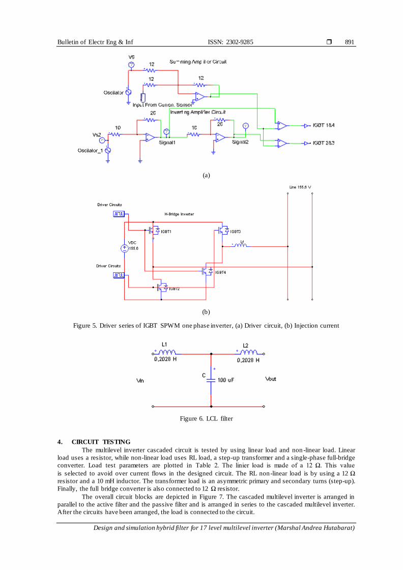
4. CIRCUIT TESTING
The multilevel inverter cascaded circuit is tested by using linear load and non -linear load. Linear
load uses a resistor, while non-linear load uses RL load, a step-up transformer and a single-phase full-bridge
converter. Load test parameters are plotted in Table 2. The linier load is made of a 12 Ω. This value
is selected to avoid over current flows in the designed circuit. The RL non-linear load is by using a 12 Ω
resistor and a 10 mH inductor. The transformer load is an asymmetric primary and secondary turns (step-up).
Finally, the full bridge converter is also connected to 12 Ω resistor.
The overall circuit blocks are depicted in Figure 7. The cascaded multilevel inverter is arranged in
parallel to the active filter and the passive filter and is arranged in series to the cascaded multilevel inverter.
After the circuits have been arranged, the load is connected to the circuit.
ISSN: 2302-9285
Bulletin of Electr Eng & Inf, Vol. 9, No. 3, June 2020 : 886 – 897
892
Table 2. Load test parameters Type of load Value of load
R Load R=12Ω R-L Load R=12Ω and L=10mH
T ransformer Load Np=200 and Ns=400
Full bridge converter load R=12Ω
Figure 7. The overall circuit block

Bulletin of Electr Eng & Inf ISSN: 2302-9285
Design and simulation hybrid filter for 17 level multilevel inverter (Marshal Andrea Hutabarat)
893
5. RESULTS AND DISCUSSIONS
5.1. Test results for non-filter inverter
Test results without filter are plotted in Table 3. The waveforms are shown in Figure 8. THDv
and THDi are generated higher than the permitted levels of IEEE 519-2014 which mean higher than
the allowed value of 8%. The test without filter produce THDv of 59.46% and THDi 59.46% for resistive
load. The RL load causes higher THDv of 65.74% and lower THDi 51.59%. Trafo step up generates lower
THD than resistive load, while the converter provides lower THDv but similar THDi to resistive load.
Table 3. Test results for non-filter inverter No Type of load THDv THDi 1 R 59.46% 59.46% 2 RL 65.74% 51.59% 3 Trafo step up 58.55% 58.14% 4 Full bridge converter 59.34% 59.46%
(a)
(b)
(c)
(d)
Figure 8. Non-filter test results, (a) R load, (b) RL load, (c) Step-up transformer load, (d) Converter load
0
-200
200
VLoad
0 0.2 0.4 0.6 0.8 1
Time (s)
0
-10
-20
10
20
IS
0
-200
200
VLoad
0 0.2 0.4 0.6 0.8 1
Time (s)
0
-10
-20
10
20
IS
0
-200
200
VLoad
0 0.2 0.4 0.6 0.8 1
Time (s)
0
-10
-20
10
20
IS
0
-200
200
VS
0 0.2 0.4 0.6 0.8 1
Time (s)
0
-20
20
IS

ISSN: 2302-9285
Bulletin of Electr Eng & Inf, Vol. 9, No. 3, June 2020 : 886 – 897
894
5.2. Test results for hybrid filter inverter
The multilevel inverter cascaded circuit is coupled with a hybrid filter and then connected to
the same load as previous test. The generated waveforms can be seen in Figure 9. The THD values are at
the permitted levels of IEEE 519-2014. The generated waveforms after filtering become sinusoidal.
(a)
(b)
(c)
(d)
Figure 9. Test results for hybrid filter, (a) R load, (b) RL load, (c) Step up transformer load,
(d) Converter load
The test results with hybrid filter installed produce THDv of 0.09% and THDi 0.09% for resistive
load. The RL load produces higher THDv of 0.11% and THDi of 0.10%. Trafo step up generates higher THD
than R load, while the converter provides higher THDv but similar THDi to R load. These values are plotted
in Table 4.
0
-100
-200
100
200
VLoad
0 0.2 0.4 0.6 0.8 1
Time (s)
0-10-20
1020
IOut
0
-100
-200
100
200
VLoad
0 0.2 0.4 0.6 0.8 1
Time (s)
0
-10
10
IOut
0
-100
-200
100
200
VOut
0 0.2 0.4 0.6 0.8 1
Time (s)
0
-40
40
IOut
0
-100
100
VOut
0 0.2 0.4 0.6 0.8 1
Time (s)
0
-10
10
IOut

Bulletin of Electr Eng & Inf ISSN: 2302-9285
Design and simulation hybrid filter for 17 level multilevel inverter (Marshal Andrea Hutabarat)
895
Table 4. Test results using the hybrid filter
No Type of load Filter Hybrid
THDv THDi
1 R 0.09% 0.09% 2 RL 0.11% 0.10%
3 4
Trafo Step Up Converter
0.23% 0.10%
1.05% 0.09%
5.3. Discussion
Simulations results show that the output waveforms of the inverter without filter are mostly
non-sinusoidal with high THD values (as shown in Table 3). By adding filter, the output waveforms become
sinusoidal with much lower THD values (as shown in Table 4). THDv and THDi of the inverter with filter
are still within the permitted level of IEEE 519-2014 which are maximum THDv is 0.1% and maximum
THDi is 1.05%. The hybrid filter is significantly reducing the output harmonics up to 65.63%.
On the other hand, filter addition to the inverter circuit causes transient phenomenon. Transient
causes output amplitude require sometime to reach typical amplitude value. It is diffrenet from non-filter
inverter that produces maximum amplitude from the beginning circuit turned on. Inductor and capasitor in
filter delayed the amplitude rise. Transient process occurs as inductor and capacitor made energy exchanges.
Step transformer load requires about 0.4 s to reach maximum amplitude, while resistive load requires
the shortest one, less than 0.2 s.
6. CONCLUSION
Power quality has become necessary since the renewable energy becomes circulating in the market.
Since renewable energy sources are dominated by DC voltage, the inverter becomes an important device.
This paper has proposed a hybrid filter insertion to the multilevel cascaded inverter to reduce voltage
and currect harmonics. The assessments using PSIM simulator show that the effectiveness of proposed
multilevel cascaded 17 level inverter with hybrid filter for four different load types. The filter is able to
reduce the THDv and THDi up to 65.63%. The active filter injected the compensation current into the circuit
and the LCL filter absorbed the harmonics that occur over the 50 HZ frequency, so that the resulting
harmonics are still within the permitted level of IEEE 519-2014. On the other hand, filter drawback on
the inverter output is injecting additional transient time to reach maximum amplitude as capacitor
and inductor exchanges energy during filtering. Even though, the output voltage is relatively stable as
transient over.
REFERENCES [1] M. H. Rahman, M. A. Mannan, M. A. Goffer Khan, M. R. U. Karim Shovon and M. M. Haq Mamun, "Design
and Implementation of a Three-Phase Inverter Operated with Different Conduction Modes," 2019 International
Conference on Robotics,Electrical and Signal Processing Techniques (ICREST), Dhaka, Bangladesh, pp. 346-349, 2019.
[2] A. Vishwitha and A. K. Bhat, "Solar Based Inverter Design: A Brief Review," in Advances in Communication,
Signal Processing, VLSI, and Embedded Systems, Springer, Singapore, pp. 463-469, 2020.
[3] S. Dandin and A. Kumari, "Highly Efficient Pure Sine-Wave Inverter for Photovoltaic Applications with MPPT
Technique," International Journal of Engineering Research & Technology (IJERT), vol. 3, no. 5, May 2014. [4] M. S. Arif, S.M. Ayob, Z. Salam, "Asymmetrical Nine-Level Inverter Topology with Reduce Power Semiconductor
Devices," Telecommunication Computing Electronics and Control, vol. 16, no. 1, pp. 38-45, Feb 2018.
[5] A. Jidin, S. Sanusi, T. Sutikno, N. R. N. Idris, "Improved Output Voltage Quality using Space Vector Modulation
for Multilevel Inverters," Telecommunication Computing Electronics and Control, vol. 14, no. 2, pp. 387-389,
Jun 2016. [6] N. Farah, M. H. N. Talib, J. Lazi, M. A. Ali and Z. Ibrahim, "Multilevel Inverter Fed Switched Reluctance Motors
(SRMs): 6/4, 8/6 and 10/8 SRM Geometric Types," International Journal of Power Electronics and Drive Systems
(IJPEDS), vol. 8, no. 2, pp. 584-592, Jun 2017.
[7] IEEE Recommended Practice and Requirements for Harmonic Control in Electric Power Systems," in IEEE Std
519-2014 (Revision of IEEE Std 519-1992) , vol., no., pp.1-29, 11 June 2014 [8] S. P. Litran and P. Salmeron, "Electromagnetic Compatibility Analysis of a Control Strategy for Hybrid Active
Filter," Electric Power Systems Research, Elsevier, vol. 144, pp. 81-88, Mar 2017.
[9] M. R. Sindhu, M. G. Nair and T. N. P. Nambiar, "Three Phase Auto-tuned Shunt Hybrid Filter for Harmonic and
Reactive Power Compensation," Procedia Technology, Elsevier, vol. 21, pp. 482-489, 2015.
[10] F. Grasso, A. Luchetta, S. Manetti, S. De Giorgis, F. Cenghialta and E. D'Antuono, "Improving power quality and efficiency in electrical plants using a three-phase series hybrid passive filter," 2016 AEIT International Annual
Conference (AEIT), Capri, pp. 1-5, 2016

ISSN: 2302-9285
Bulletin of Electr Eng & Inf, Vol. 9, No. 3, June 2020 : 886 – 897
896
[11] V. S. R. V. Oruganti, et al., "Real-time control of hybrid active power filter using conservative power theory in
industrial power system," IET Power Electronics, vol. 10, no. 2, pp. 196-207, 2017. [12] S. Sellakumar, et al., "Dynamic Hybrid Shunt Active Filter to Reduce the THD in 415 V, 50 Hz Distribution
System," National Journal on Electronic Sciences and Systems, vol. 4, no. 1, 2013.
[13] G. Tsengenes, T. Nathenas and G. Adamidis, "A three-level space vector modulated grid connected inverter with
control scheme based on instantaneous power theory ," Simulation Modelling Practice and Theory, vol. 25,
pp. 134-147, Jun 2012. [14] C. C. Hua and C. W. Chuang, "Design and implementation of a hybrid series active power filter," in 2005
International Conference on Power Electronics and Drives Systems, vol. 2, pp. 1322-1326, 2005.
[15] Yongqiang Lang, Dianguo Xu, S. R. Hadianamrei and Hongfei Ma, "A Novel Design Method of LCL Type Utility
Interface for Three-Phase Voltage Source Rectifier," 2005 IEEE 36th Power Electronics Specialists Conference,
Recife, pp. 313-317, 2005. [16] W. Tang, Y. Song, R. Cheng and K. Ma, "Current Ripple Oriented Design of LCL Filter for Three-Phase Voltage-
Source Converter with Different Wire Connections and Modulations," 2018 IEEE Energy Conversion Congress
and Exposition (ECCE), Portland, OR, 2018, pp. 5887-5891.
[17] X. Shi, Z. Wang, Y. Ma, L. Hang, L. M. Tolbert and F. Wang, "Modeling and control of an LCL filter based three-
phase active rectifier in grid emulator," 2013 Twenty-Eighth Annual IEEE Applied Power Electronics Conference and Exposition (APEC), Long Beach, CA, 2013, pp. 992-998.
[18] Yong-Sin Jin, Hee-Keun Shin, Hag-Wone Kim, Kwan-Yuhl Cho and Byung-Kook Lim, "A carrier comparison
PWM method for reducing input current THD of three-phase PWM rectifier," Proceedings of The 7th International
Power Electronics and Motion Control Conference, Harbin, 2012, pp. 3015-3020.
[19] A. Marzouki, M. Hamouda and F. Fnaiech, "Sensorless nonlinear control for a three-phase PWM AC-DC converter," 2010 IEEE International Symposium on Industrial Electronics, Bari, 2010, pp. 1052-1057.
[20] A. Marzouki, M. Hamouda and F. Fnaiech, "A hybrid controller for PWM active rectifiers based LCL
filters," COMPEL: The International Journal for Computation and Mathematics in Electrical and Electronic
Engineering, vol. 34, no. 4, pp. 1229-1251, Jul 2015.
[21] P. Thirumoorthi and N. Yadaiah, "Design of current source hybrid power filter for harmonic current compensation," Simulation Modelling Practice and Theory, vol. 52, pp. 78-91, Mar 2015.
[22] B. Singh, V. Verma, A. Chandra and K. Al-Haddad, "Hybrid filters for power quality improvement," in IEE
Proceedings - Generation, Transmission and Distribution, vol. 152, no. 3, pp. 365-378, 6 May 2005.
[23] G. N. Rao, P. S. Raju, K. C. Sekharc, "Harmonic Elimination of Cascaded H-Bridge Multilevel Inverter Based Active Power Filter Controlled By Intelligent Techniques," International Journal of Electrical Power and Energy
Systems, Elsevier, vol. 61, pp. 56-63, Oct 2014.
[24] C. Bharatiraja and Latha, "A New Asymmetrical Single Phase 15 Level Reduced Switch Multilevel Voltage Source
Inverter," Journal of Electrical Engineering, vol. 15, pp. 1-9, Jan 2015.
[25] C. H. Cheng, "Design of Output Filter for Inverter Using Fuzzy logic," Expert Systems with Applications: An International Journal, vol. 38, no 7, pp. 8639-8647, Jul 2011.
[26] V. A. Lacerda, D. V. Coury and R. M. Monaro, "LCL Filter Design For VSC-HVDC Systems Supplying Passive
Grids," Electric Power Systems Research, Elsevier, vol. 152, pp. 160-167, Nov 2017.
[27] M. Venkatesan, R. Rajeswari, M. Kaliyamoorthy, M. Srithar, "Transient and Steady State Analysis of Modified
Three Phase Multilevel Inverter for Photovoltaic System," International Journal of Power Electronics and Drive Systems, vol. 8, no. 1, pp. 31-39, Mar 2017.
[28] M. B. Saïd-Romdhane, M. W. Naouar, I. S. Belkhodja and E. Monmasson, "Simple and Systematic LCL Filter
Design for Three-Phase Grid-Connected Power Converters," Mathematics and Computers in Simulation, Elsevier,
vol. 130, pp. 181-193, Dec 2016.
BIOGRAPHIES OF AUTHORS
Marshal Andrea Hutabarat is finished his Master of Engineering (MEng) in electrical
engineering from University of North Sumatera in 2017. He receives a scholarship from his
institution for his Master of Science (MSc) degree which he is currently pursuing in The Australian National University (ANU) in Business Information System.
Syafruddin Hasan was born in July 1, 1959 in Pidie, Aceh-Indonesia. He received his BSc from
Universitas Sumatera Utara (USU) Medan in 1985, MSc from Institut Teknologi Bandung (ITB)
Bandung-Indonesia in 1993, and PhD from Universiti Malaysia Perlis (UniMAP) in 2014, all in
Electrical Engineering. He is a lecture in USU. His field of interest includes Electromagnetic Theory, Electrical Machines, Power Electronic Drives and Power Quality.

Bulletin of Electr Eng & Inf ISSN: 2302-9285
Design and simulation hybrid filter for 17 level multilevel inverter (Marshal Andrea Hutabarat)
897
Ali Hanafiah Rambe received his BSc from Universitas Sumatera Utara, Indonesia, MSc from
Universitas Indonesia, and PhD from Universitas Sumatera Utara His field of interest includes
Electromagnetic Theory, Transmission Lines, and Antennas.
Suherman completed BSc in Electrical Engineering, Universitas Sumatera Utara, Indonesia in
2000, MSc in Networked and Distributed System, RMIT, Australia in 2009, and PhD in
Electrical and Electronics Engineering from De Montfort University, UK in 2013. He is
currently a lecturer within Electrical Engineering Department, Universitas Sumatera Utara.