Design and Seismic Prevention of Water Main crossing ... · Design and Seismic Prevention of Water...
11
1 Design and Seismic Prevention of Water Main crossing Faults Cases in Taiwan Y.S Lai Y.C. Chou 2 , J.L. Lin 2 , J.Z. Liao 2 , J.J Chen 2 1 Region Engineering Office, Taiwan Water Company 2 CECI Engineering Consultants, Inc., Taiwan. Keywords:Shan-Yi active fault, water main, shield tunnel Abstract Design of underground pipeline should consider the geology, environment and influence of active fault. Two cases of water mains seismic strategy passing through active faults will be discussed. First is TWC water main project, its alignment is close and almost parallel to the Shan-Yi active fault in Miao-Li. The pipeline will cause severer damage than the situation just cross the fault, such as the Taipei Dadu water main project (alignment is cross Shan-chiao active fault). Meanwhile, the seismic design strategy and analysis is totally different. This paper will demonstrates the TWC project feasible engineering judgments, design with BIM techniques and the shield tunneling consideration in hard gravel formation as reference. 一、 Foreword For water supply in urban area, some pipeline being parallel or crossing active fault should be considered. TWC water main project alignment is parallel with San-Yi active fault, maintenance walkway space is kept within shield tunnel. The main design task is to analyze influence of earthquake waves. Taipei Dadu water main project alignment is cross Shan-chiao active fault, the main design task is to analyze displacement of fault moving. Owing to complicated pipeline layout, these two
Transcript of Design and Seismic Prevention of Water Main crossing ... · Design and Seismic Prevention of Water...
1
Design and Seismic Prevention of Water Main crossing
Faults Cases in Taiwan
Y.S Lai Y.C. Chou2, J.L. Lin2, J.Z. Liao2, J.J Chen2
1Region Engineering Office, Taiwan Water Company
2CECI Engineering Consultants, Inc., Taiwan.
Keywords:Shan-Yi active fault, water main, shield tunnel
Abstract
Design of underground pipeline should consider the geology, environment and
influence of active fault. Two cases of water mains seismic strategy passing through
active faults will be discussed. First is TWC water main project, its alignment is close
and almost parallel to the Shan-Yi active fault in Miao-Li. The pipeline will cause
severer damage than the situation just cross the fault, such as the Taipei Dadu water
main project (alignment is cross Shan-chiao active fault). Meanwhile, the seismic
design strategy and analysis is totally different. This paper will demonstrates the TWC
project feasible engineering judgments, design with BIM techniques and the shield
tunneling consideration in hard gravel formation as reference.
一、 Foreword
For water supply in urban area, some pipeline being parallel or crossing active fault
should be considered. TWC water main project alignment is parallel with San-Yi
active fault, maintenance walkway space is kept within shield tunnel. The main
design task is to analyze influence of earthquake waves. Taipei Dadu water main
project alignment is cross Shan-chiao active fault, the main design task is to analyze
displacement of fault moving. Owing to complicated pipeline layout, these two

2
cases consider 3-D numerical analysis model instead of conventional plane strain
method.
二、Dynamic analysis method of water main tunnel
Influence of earthquake induced by active faults moving can be classified
into two types. Type I consider influence of water main structure from fault
moving wave, ex. TWC project. TypeII consider influence of water main
structure from fault moving displacement, ex. Dadu project.
2.1 Influence of water main structure from fault moving wave analysis
2.1.1 Racking method
Analysis of underground structure such as water main is different from
general structure. Racking method is adopted usually, where the racking angle
is given to simulate stratum deformation. The racking angle is seldom less
than 0.5%, and is related to stratum SPT-N value.
The racking deformation induced by earthquake force within free domain
is calculated as follow equation.
seC
VIR
max
Where I=1.2 is importance coefficient, Vmax is largest velocity of ground
movement, and Cse is stratum shear velocity, which can be estimated as
follow equations if no measured value.
31
100NCSe (Cohesive soil)
3
1
80NCSe (Cohesionless soil)
The TWC project consider joint between launching shaft and shield
tunnel by racking method, where stress concentration occurs as Fig.1a and 1b.
To analyze soil structure interaction(SSI) effect, numerical analysis must

3
involve structure and surrounding soil, which will take more time to calculate.
Fig.1a Analysis Mesh of launching shaft and shield tunnel
Fig.1b Stress increasing contour of racking method
2.1.2 Response Spectrum Analysis
The TWC project in shield tunnel with maintenance walkway space,
which is surrounded by air instead of soil, thus racking method is not
available.

4
Fig.2 3-D layout of TWC project water main
Response spectrum analysis is more usually adopted than time domain
analysis due to calculation time is less, especially for the complicated degrees
of freedom.
Usually we take basic mode instead of high frequency mode to simulate
dynamic analysis, so 10 modes is progressed of TWC project as Fig3. The 10
modes earthquake response of TWC project can be got after calculation of
both modes frequency and acceleration spectrum from NCREE, where the 1 st
mode(0.73Hz) and 4 th mode(1.83Hz) contribute 70% and 16% of earthquake
response. Thus the dynamic behavior is composed of 1st mode and 4th mode.

5
Fig.3 Related frequency of 10 modes frequency of TWC project
三、Introduction of TWC water main project
The TWC project locates on Sanyi Township, Miaoli County. Where φ
1000mm water main is 1416 meters long within shield tunnel, and connected
with φ1000mm pipe lines at both ends to supply water for neighbourhood
area. The project location is shown of Fig.5

6
Fig.5 Location of TWC project
3.1 Location
The TWC project is located under No.13 provincial road within a tourist
spots, as shown of Fig.6.
Fig.6 Photos of TWC project
3.2 Topography, Geology and Groundwater
3.2.1 Topography and Geology
The site elevation is 310~365 meters at hill area with gravel formation,
where gravel diameter is 0.2~1.0 meters.
The geological structures at site neighborhood are syncline and San-Yi
0k+000路線起點
1k+300水美街
0k+700自來水設施
0k+200水美街
0k+500水美街
0k+950水美街
1k+200水美街
1k+416路線終點
發進井
到達井

7
active fault. Where San-Yi active fault locates 170~230 meters from site with
apparent influence of TWC project. The site geological map is shown as Fig.7
Fig.7 Geological map and profile of TWC project
3.2.2 Groundwater
Most of the project alignment is above groundwater level after boring
observation as shown of Fig.8. Groundwater level near launching shaft is
about -5.7~-12.6 meters, and about -40.0m of arrival shaft.

8
Fig.8 Groundwater condition
3.2.3 Engineer Geology
The site formation include overlay, sandy silt and gravel. The
gravel uniaxial compression strength is between 735~1475 kgf/cm2.
The simplified stratum parameters is shown as Table 1.
Table 1 Simplified stratum parameters
layer Stratum Depth
(m)
SPT-N
value
γt
(t/m3)
c
(t/m2)
ϕ
(deg.)
1 Overlay 1.2 - 1.80 0 29
2 Sandy silt 3.2 9 1.91 0 31
3 Gravel 40 50 2.10 0 35
9
3.3 Shield Tunnel Design
3.3.1 Tunnel alignment
The TWC project should consider shield tunnel construction and pipe
installation. Especially the tunnel overburden depth, alignment slope and
smallest drainage slope in tunnel.
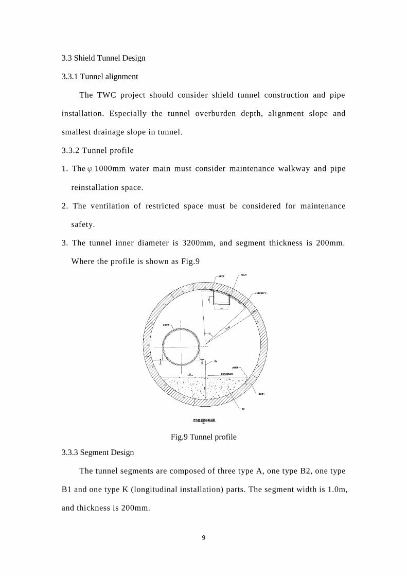
3.3.2 Tunnel profile
1. Theφ1000mm water main must consider maintenance walkway and pipe
reinstallation space.
2. The ventilation of restricted space must be considered for maintenance
safety.
3. The tunnel inner diameter is 3200mm, and segment thickness is 200mm.
Where the profile is shown as Fig.9
Fig.9 Tunnel profile
3.3.3 Segment Design
The tunnel segments are composed of three type A, one type B2, one type
B1 and one type K (longitudinal installation) parts. The segment width is 1.0m,
and thickness is 200mm.

10
3.4 Launching and Arriving shaft
1. The shaft diameter is 8 to 10 meters for shield construction and pipe
installation needs.
2. Launching shaft caisson depth is 12 meters with press -in assistant method.
The layout is shown as Fig.10 and Fig.11.
Fig.10 Location of Launching shaft Fig.11 A-A profile of launching shaft
3. Arrival shaft depth is 29 meters, which is constructed by Liner plate method.
The layout is shown as Fig.12 and Fig.13.
Fig.12 Location of Arrival shaft Fig.13 A-A profile of Arrival shaft
11
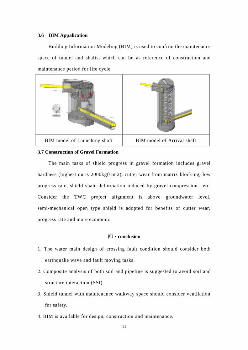
3.6 BIM Appalication
Building Information Modeling (BIM) is used to confirm the maintenance
space of tunnel and shafts, which can be as reference of construction and
maintenance period for life cycle.
BIM model of Launching shaft BIM model of Arrival shaft
3.7 Construction of Gravel Formation
The main tasks of shield progress in gravel formation includes gravel
hardness (highest qu is 2000kgf/cm2), cutter wear from matrix blocking, low
progress rate, shield shale deformation induced by gravel compression…etc.
Consider the TWC project alignment is above groundwater level,
semi-mechanical open type shield is adopted for benefits of cutter wear,
progress rate and more economic.
四、conclusion
1. The water main design of crossing fault condition should consider both
earthquake wave and fault moving tasks.
2. Composite analysis of both soil and pipeline is suggested to avoid soil and
structure interaction (SSI).
3. Shield tunnel with maintenance walkway space should consider ventilation
for safety.
4. BIM is available for design, construction and maintenance.