DESIGN AND PERFORMANCE ANALYSIS OF A TURBOFAN …
18
www.tjprc.org [email protected] DESIGN AND PERFORMANCE ANALYSIS OF A TURBOFAN ENGINE FOR OPTIMAL OPERATION P. B. Sob Department of Mechanical Engineering, Faculty of Engineering and Technology, Vaal University of Technology, Vanderbijlpark 1900, Private Bag X021, South Africa ABSTRACT Engine efficiency and transient performance are vital in a turbofan engine. This affects drivability and fuel consumption in a turbofan engine. The main problem faced by a turbofan engine constitutes low response in a low-speed operation and this often creates “turbo lag” which affects turbofan engine performance and efficiencies. A hybrid turbofan engine design system is a promising technology for improving efficiency and performance during the operation. This research studies the possibility of implementing a hybrid turbofan engine design for optimal performance. The major parameters that impact thermal, propulsive and overall efficiency are modelled and characterized for optimal performance. The tool of SOLIDWORKDS CFD and CAD are used in modelling and simulation of the critical parameters that impacts performance. Correlation analysis of the critical design parameters for optimal performance is revealed. The following facts are theoretically revealed and validated. It was shown that the performance of the system is greatly influenced by thermal properties and the vane angular flow geometry. It was also revealed that there are critical operating variables that gave optimal performance of the turbofan engine during operation. It was also shown that the thermal, propulsive and overall efficiency are geometrically characterised by the system mass flow rate of air and ambient pressure of the system during throttling. It was observed that the system performance and system efficiency significantly increased at low speed. This was alluded to the fact that at optimal design performance proper mechanical hybrid calibration was done at varying effective mass flow rate of air in the system. KEYWORDS: Hybrid turbofan engine, Performance, Efficiency & Vane geometry Received: Jan 23, 2021; Accepted: Feb 13, 2021; Published: Mar 25, 2021; Paper Id.: IJMPERDAPR202131 NOMENCLATURE A cross-sectional area a the system speed of sound CP the system effective specific heat at constant pressure in the system D the system-drag force during operation e the system polytropic efficiency during operation F the system force uninstalled thrust during operation f the fuel-air ratio in the system gc the system Newtonian constant during operation h the system enthalpy Original Article International Journal of Mechanical and Production Engineering Research and Development (IJMPERD) ISSN (P): 2249–6890; ISSN (E): 2249–8001 Vol. 11, Issue 2, Apr 2021, 427-444 © TJPRC Pvt. Ltd.
Transcript of DESIGN AND PERFORMANCE ANALYSIS OF A TURBOFAN …

www.tjprc.org [email protected]
DESIGN AND PERFORMANCE ANALYSIS OF A TURBOFAN ENGINE FOR
OPTIMAL OPERATION
P. B. Sob
Department of Mechanical Engineering, Faculty of Engineering and Technology, Vaal University of Technology,
Vanderbijlpark 1900, Private Bag X021, South Africa
ABSTRACT
Engine efficiency and transient performance are vital in a turbofan engine. This affects drivability and fuel consumption
in a turbofan engine. The main problem faced by a turbofan engine constitutes low response in a low-speed operation
and this often creates “turbo lag” which affects turbofan engine performance and efficiencies. A hybrid turbofan engine
design system is a promising technology for improving efficiency and performance during the operation. This research
studies the possibility of implementing a hybrid turbofan engine design for optimal performance. The major parameters
that impact thermal, propulsive and overall efficiency are modelled and characterized for optimal performance. The tool
of SOLIDWORKDS CFD and CAD are used in modelling and simulation of the critical parameters that impacts
performance. Correlation analysis of the critical design parameters for optimal performance is revealed. The following
facts are theoretically revealed and validated. It was shown that the performance of the system is greatly influenced by
thermal properties and the vane angular flow geometry. It was also revealed that there are critical operating variables
that gave optimal performance of the turbofan engine during operation. It was also shown that the thermal, propulsive
and overall efficiency are geometrically characterised by the system mass flow rate of air and ambient pressure of the
system during throttling. It was observed that the system performance and system efficiency significantly increased at low
speed. This was alluded to the fact that at optimal design performance proper mechanical hybrid calibration was done at
varying effective mass flow rate of air in the system.
KEYWORDS: Hybrid turbofan engine, Performance, Efficiency & Vane geometry
Received: Jan 23, 2021; Accepted: Feb 13, 2021; Published: Mar 25, 2021; Paper Id.: IJMPERDAPR202131
NOMENCLATURE
A cross-sectional area
a the system speed of sound
CP the system effective specific heat at constant pressure in the system
D the system-drag force during operation
e the system polytropic efficiency during operation
F the system force uninstalled thrust during operation
f the fuel-air ratio in the system
gc the system Newtonian constant during operation
h the system enthalpy
Orig
ina
l Article
International Journal of Mechanical and Production
Engineering Research and Development (IJMPERD)
ISSN (P): 2249–6890; ISSN (E): 2249–8001
Vol. 11, Issue 2, Apr 2021, 427-444
© TJPRC Pvt. Ltd.

428 P. B. Sob
Impact Factor (JCC): 9.6246 NAAS Rating: 3.11
hPR the system low heating value of fuel during operation
M the system Mach number
m
the effective mass flow rate during operation
P pressure
Pt total pressure
Q
rate of thermal energy released or absorbed
R the effective universal gas constant during operation
S the system undersigned thrust specific fuel consumption during operation
T the system temperature or designed thrust during operation
TSFC the system designed specific fuel consumption during operation
Tt the system effective temperature during operation
V the system effective velocity during operation
W
the system power
α the bypass ratio of the system during operation
γ the system ratio of specific heats during operation
m the system mechanical efficiency during operation
ηO the system overall efficiency during operation
ηP the system propulsive efficiency during operation
ηT the system thermal efficiency during operation
π the system ratio of effective pressure during operation
πr The system exceptional ratio between the effective pressure and stationary pressure due to the effect of
ram in the system during operation, P
Pt
τ the system ratio of effective temperature during operation
r the system exceptional ratio between effective temperature and stationary temperature due to the
effective ram motion during operation, T
Tt

Design and Performance Analysis of a Turbofan Engine for Optimal Operation 429
www.tjprc.org [email protected]
τλ the ratio between effective enthalpy in the system and the effective enthalpy at ambient
condition during operation
SUBSCRIPTS
b the major burner or the major properties between the burner outlet and ITB
c the properties between the system upstream and burner or engine core during operation
d the system diffuser during operation
e the system outlet during operation
f the fan of the system
fn the fan-nozzle of the system
HPC the effective high pressure compressor during operation
HPT the system high pressure turbine
ITB the system inter-stage turbine combustors during operation
LPC compressor low pressure
LPT turbine low pressure
O input
n the nozzle
t the ITB exit properties between and the downstream or effective-stagnation properties of temperature,
pressure or enthalpy
INTRODUCTION
The First Turbo fan engine was Rolls-Royce design of RB.80 Conway being manufactured by Rolls-Royce manufacturing
Limited in the early 1950s (1-10). It contained an axial Flow compressor with a stage of 7 compressors at low pressure and
a stage of 9 high-pressure compressors (1-12). Maximum thrust was 76.3kN and a bypass ratio of 0.25 but in 1959,
improvements were made by Rolls Royce and the Rolls-Royce Pegasus came to life (1-13). This engine is able to direct
thrust and manoeuvre vertically for take-off and landing (11-20). It had a 2 spool Turbofan compressor, a stage 3 lower
pressure, and a stage 8 axial flow high pressure compressor (20-30). The maximum thrust went up to 106Kn and in the
1960s, Pratt & Whitney and Volvo Flag motor came out with a Volvo RM8 (1-12). It had an axial flow compressor, a
stage-3 fan, stage 3 lower pressure and stage-7 higher pressure (17-22). The system had 9 combustion chambers design in
can-annular arrangement with an injector of 4 in each combustion chambers and a thrust which is maximum at 72.2Kn
during operation. In the early 1960s, research such as Gareth Air & Honeywell Aerospace designed a Garrett ATF3 system
and a turbine of 3 spool engine (1-12). The design system compressor is having a low pressure single stage fan and a stage
5 axial pressure intermediate pressure compressor and a high pressure single centrifugal compressor (10-15). The design
system turbine is a high pressure single and a 3 stage intermediate pressure and a stage-2 low pressure system having a
maximum thrust of approximately 24.20kN and take off at 4.69kN during operation.

430 P. B. Sob
Impact Factor (JCC): 9.6246 NAAS Rating: 3.11
Rolls-Royce came out with another one in 1960, a Rolls-Royce RB211 capable of generating 166 to 270kN of
thrust (11-30). This includes a stage-6 compressor of high pressure, a stage-7 compressor of low pressure (10-30), a high
pressure single stage turbine and a low pressure single stage turbine. In the 1970s, Pratt & Whitney manufactures the Pratt
& Whitney F100 (1-16). This was an after burning turbofan. The Maximum thrust is 64.9kN and 105.7kN with an
afterburner and later in the 1980s, Pratt & Whitney designed a high turbo fan bypass engine of PW4000 having a thrust
ranging from 230-441Kn (11-30). Later in 1990, Rolls Royce designed a Rolls-Royce Trent range having a 3 spool high
bypass turbofan engine aircraft having a thrust between 240kN-420Kn (1-12). The turbofan engine has gone through
several modifications for decades and the turbofan engine has an application in several aviation and energy production
fields (22-30). Several modern design of turbofan system uses knowledge from different engineering fields which includes
heat transfer, fluid mechanics and thermodynamics (1-23). Several jet engines have under gone several design
modifications and improvements for several decades and this has led to performance and improvements in reliability and
efficiency (1-23). However, the most commonly used turbojet engines are the turboprop engine design, the turbofan engine
design, the turbo shaft design and the ramjet engine design being used (1-13). All these designed turbofan engine work on
the same fundamental principles on the operating theory of internal combustion theory of suck, squeeze, bang and blow.
Figure 1: Four types of Gas Engine
In this research study, the main focus is the design of turbofan engine which will offer better fuel economy and
that will lead to the design of an advanced or modified jet engine with better overall efficiency. This was achieved by
looking at the main working principle of a turbofan engine as shown in Figure 2 (a)
Figure 2 (A) Working Principale of a Turbofan Engine (B) A Gas Generator Propulsion System (C) A Turbo Jet
Engine
From design engineering, the first important component is the inlet section of air into the system (1-15). During
operation, air is being sucked and compressed to a higher pressure line and the compressed air in the system is mixed with
fuel-air ratio and gets ignited during the power stroke (1-11). The ignited air-fuel-mixture discharges at a high velocity

Design and Performance Analysis of a Turbofan Engine for Optimal Operation 431
www.tjprc.org [email protected]
during the exhaust stokes during operation. These concepts have been applicable in designing most jet engines with
different design modification to enhance performance, efficiency, reliability and fuel economy (1-11). In most engine
design, turbofan system and turbine are connected to the compressor and a fan is used to propel air through a duct. The
system is designed to propel incoming air at a relative speed to the system and then the air is being compressed by the inlet
at a high pressure to sustain combustion (1-10). It is this force of the air that propels the aircraft at optimal speed during
operation. During the engine operation, there are different cycles in the turbine that impact performance, efficiency and
reliability of the system.
The ideal cycles of a turbofan engine are simplified as a thermodynamic closed cycles and it is used to analyse
critical process of combustion, expansion and compression, combustion during the engine operation with more focus on
the extraction of work during combustion process of air-fuel mixture (1-22). A complete process of parametric cycle and
system analysis of the ideal turbofan air-breathing propulsion system is being produced with a common system of air-
breathing propulsion of the engines during the operation (1-14). The system consists of three main components in design
concept and they are the compressor, the combustor, and the turbine being shown schematically in Figure 2(b). The main
idea behind a gas turbine generator is mainly to convert the intake air mixture and fuel ratio into the system high
temperature and system high gas pressure (12-22). Based on the design application and design concept of the gas turbine
system, the energy in the system is being extracted and used in different design system and applications such as turbojet,
turbofan, turbo-shaft, turboprop, and ramjet in different mechanical system (10-24).
A unique designed turbojet engine is being designed mainly by adding an input and a nozzle system as shown in
Figure 2 (c). The designed nozzle in the system converts the internal energy from the system of the hot gas into thrust of
kinetic energy being used by the system (10-23). The main work being extracted by designed turbine is mainly to drive the
compressor of the system. For a turbofan, turboprop and turbo-shaft engine, the main work from the turbine system is
needed to drive a shaft for the turbo-shaft, a fan for the turbofan, and a propeller in the turboprop; in addition, it is used to
driving the compressor (1-16). The system ramjet in the engine mainly consists of an inlet, a combustor, and a nozzle at the
discharge. The system does not need the compressor due to the fact that the inlet already uses a ram air-compressing
mechanism of the system such that of air intake has enough kinetic energy to increase the system pressure during operation
(22-30). The primary objective of this research is to determine the unique relationship between the performance of the
engine system such as the specific thrust, thrust-specific fuel consumption and determine major design parameters of
compressor pressure ratio, fan pressure ratio, bypass ratio to design and constraints the burner exit temperature, compressor
exit pressure, and to flight environment (Mach number, ambient temperature, ambient pressure).
METHODOLOGY
To design a turbofan engine that is efficient in performance, the operating parameters of the turbofan engine must be model
for optimal performance. To model the operating parameters, it is vital to model the thrust force of the system during
operation. Thrust force needed to sustain the flight must be proportional to the drag force (thrust = drag). During
accelerated flight, the system thrust force during operation must be greater than the system drag force (thrust > drag).
During the deceleration process, the thrust force of the system must be less than the drag force (thrust < drag). From the
control volume of the turbo fan engine as shown in Figure 2 (a-c), it is possible to apply momentum mass flow balance to
the control volume of the system. By assuming a thrust force that is uninstalled during operation in a jet engine (single inlet
and single exhaust), the system expression can be given as

432 P. B. Sob
Impact Factor (JCC): 9.6246 NAAS Rating: 3.11
APP
g
VmVmmeoe
c
oe ofueloF
[1]
Where mm fuelo
..
, represent the mass flow rates of air and fuel during operation, VV eo ,
represents the system
velocities at the system inlet and exit during operation, and PP eo , represents the pressures of the system at inlet and
exit during operation and the ideal case in the system, the hot gas in the system is being expanded to the system ambient
pressure during operation and this gives Pe = Po. The system of equation derived by equation (1) can be modified to have.
g
VmVmm
c
oe ofueloF
[2]
The thrust for T in the system is given by
DDFTnozzleinlet
[3]
Where; Dinlet and Dnozzle are the drag force in the system during operation from the inlet and the nozzle of the
system. The system specific fuel consumed in the system is the rate of fuel being propelled by the system per unit of thrust
produced by the system during operation. The specific fuel consumed by the system and the TSFC fuel consumed, S, is
given as
T
mTSFC fuel
[4]
F
mS fuel
[5]
The system efficiency during operation is a ratio of the useful work performed in the system or total energy being
expended or heat taken into the system during operation. The major parameters in the system that affect the system
efficiency during operation are the thermal efficiency, propulsive efficiency, and overall efficiency during operation. The
system thermal efficiency being characterized by the total energy output from the system (shaft work) being divided by the
available thermal energy produced by the engine.
Q
W
in
out
T
[6]
Where
Design and Performance Analysis of a Turbofan Engine for Optimal Operation 433
www.tjprc.org [email protected]
hmreleasedenergythermalofrateQ
engineofoutpowernetW
efficiencythermal
PR
out
T
fin
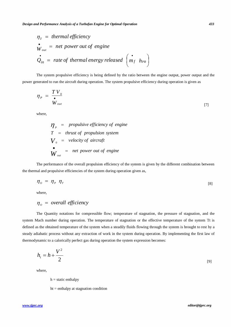
The system propulsive efficiency is being defined by the ratio between the engine output, power output and the
power generated to run the aircraft during operation. The system propulsive efficiency during operation is given as
W
VT
out
P 0
[7]
where,
engineofoutpowernet
aircraftofvelocity
systempropulsionofthrustT
engineofefficiencypropulsive
W
V
out
P
0
The performance of the overall propulsion efficiency of the system is given by the different combination between
the thermal and propulsive efficiencies of the system during operation given as,
TPO
[8]
where,
efficiencyoverallO
The Quantity notations for compressible flow; temperature of stagnation, the pressure of stagnation, and the
system Mach number during operation. The temperature of stagnation or the effective temperature of the system Tt is
defined as the obtained temperature of the system when a steadily fluids flowing through the system is brought to rest by a
steady adiabatic process without any extraction of work in the system during operation. By implementing the first law of
thermodynamic to a calorically perfect gas during operation the system expression becomes:
2
2Vhht
[9]
where,
h = static enthalpy
ht = enthalpy at stagnation condition

434 P. B. Sob
Impact Factor (JCC): 9.6246 NAAS Rating: 3.11
V = velocity
By assuming that the specific heat coefficient is constant and the expression is given as:
C
VTT
P
t
2
2
MTT t
2
2
11
[10]
where,
heatsspecificofratio
numberMachM
etemperaturstaticT
etemperaturstagnationT t
The pressure of stagnation or the total pressure in the system Pt is given as the pressure being achieved when a
steady fluid flowing fluid in the system brought to rest by the system in an adiabatic and reversible process during
operation. The effective pressure in the system during operation which affect the system performance during operation is
given by obtaining the system isentropic relation during operation given by the total pressure in the system given as
MPPt2
2
11
1
[11]
From the obtained equation (11) being derived as affected by several operating factors such as the ratio of
effective temperature in the system during operation τ and the total pressure ratio π across the system being given by d for
diffuser, LPC for the low pressure compressor during operation, HPC for compressor high pressure, b for main burner, ITB
for inter-stage turbine burner, LPT for low pressure of the turbine, HPT for high pressure of the turbine, n for nozzle, and f
for fan.
For example:
diffuserenteringpressuretotal
diffuserleavingpressuretotald
diffuserenteringetemperaturtotal
diffuserleavingetemperaturtotald
For exception the free stream, the ram, define asτr as a ratio of the total temperature and static temperature of the
system and πr as a ratio of the effective pressure and static pressure.
MT
T t
r 02
0
0
2
11
[12]

Design and Performance Analysis of a Turbofan Engine for Optimal Operation 435
www.tjprc.org [email protected]
MP
Pt
r 02
2
11
1
0
0
[13]
From expression (12) and (13), the performance of the system can be investigated during operation for an
effective design and analysis of a turbofan engine that can operate better even at low speed.
1.1 Performance Component of the System
The system analysis is more acceptable during operation when assumed that the fluid in the working system of the
engine can be rationalised as a perfect gas of the system during operation. The properties of ideal gas in the system during
operation greatly depend on the temperature of the system. The system cycle of operation allows fluid of varying
properties across the engine during operation to stay at a constant fluid properties during operation from the system main
burner entrance upstream during operation (Cpc, γc), from ITB entrance in the system to the main burner exit (Cpb, γb) of
the system, and from ITB exit downstream of the system (Cpt, γt). The Inlet of the system and pressure of diffuser losses
usually occur due to the friction that takes place in the inlet wall. The effective pressure ratio in the system πd is always
less than 1 during operation. In supersonic flight system, the pressure losses may cause shock waves in the system during
the operation which produces a greater pressure loss in the system during operation. The inlet total pressure of the system
is defined as the product of the ram pressure ratio during operation and the diffuser pressure ratio of the system during
operation. The portion of the system pressure loss due to the shock waves during operation and wall friction of the system
during operation is defined by:
rdd max [14]
1.2 Turbine and Compressor During
The efficiency of the compressor during operation is measured through two main different efficiencies of the
system during operation given as isentropic efficiency and poly-tropic efficiency of the system and the system isentropic
efficiency is given as
1
11
c
c
c
c
c
c
givenforncompressioofworkactual
givenforncompressioofworkideal
[15]
The poly-tropic efficiency is defined as
changepressurealdifferentiaforncompressioofworkactual
changepressurealdifferentiaforncompressioofworkidealec
[16]
With design assumption constant taken as ec, the relationship between τc and πc for the system during operation
given as

436 P. B. Sob
Impact Factor (JCC): 9.6246 NAAS Rating: 3.11
c
ecccc
1
[17]
The isentropic efficiency of turbine isentropic, poly-tropic efficiency of turbine and the relationship between τt
and πt can be given as:
t
t
t
t
t
tgivenforworkturbineactual
givenforworktubineideal
11
1
[18]
ttet1
The different efficiencies are impacted by the bypass ratio between the mass flow rate of the stream flowing in the
bypass and the mass flow rate entering the core. The Turbofan conceptualized is a high bypass ratio because of its function
but can be categorized in terms of being a high bypass ratio turbofan and a low bypass ratio. Turbofan entails the use of a
fan with a large diameter that directs much air around the Turbine. High Bypass ratio Turbo fans consist of a large fan in
front of the core inlet. The air passes through the fan first and compressed partially. The Mach number is from 0.75 to 0.9.
Most of the air bypasses the core and goes directly to the exhaust nozzle. The fan in a high bypass turbofan is large and
forces a large volume of air in its ducts. This generates more thrust and is fuel efficient and less noisy. High bypass ratios
are able to obtain the highest propulsion efficiencies. The disadvantage of high bypass ratio is the use of fans with large
diameters. This translates to heavier components increasing the difficulty to install the engine and maintaining sufficient
ground clearance on Aircrafts. The general appearance is the same as the High Bypass ratio turbofan. The Mach number is
a low supersonic range from 1 up until 2. The lower the total flow in the fan the higher the fan pressure ratio. These
engines are designed to operate at a low supersonic range and the thrust is not as sufficient as the High bypass ratio. The
advantage is that they are accommodating in terms of having small fan diameters and air undergoes efficient air
compression. They can take off at high-altitude points and under high temperature conditions. Their weight accommodates
combat manoeuvres at high supersonic flight speeds. The disadvantage is the insufficient thrust which means they operate
in short durations.
RESULTS AND DISCUSSIONS
This section deals with simulation results and discussion of the turbofan engine. The simulation was done using
SOLIDWORKS (CFD SIMULATION). It was also important to include three and two –dimensional CAD drawing.
Design Modeling of Turbofan

Design and Performance Analysis of a Turbofan Engine for Optimal Operation 437
www.tjprc.org [email protected]

438 P. B. Sob
Impact Factor (JCC): 9.6246 NAAS Rating: 3.11
Figure 3: Solid works (CFD Simulation of Design System

Design and Performance Analysis of a Turbofan Engine for Optimal Operation 439
www.tjprc.org [email protected]
The Computational fluid dynamics (CFD) was used to perform the calculations required to simulate the free-
stream flow of the fluid, and the interaction of the fluid (liquids and gases) with surfaces defined by boundary conditions.
With high-speed supercomputers, better solutions were achieved and are often required to solve the largest and most
complex problems in such design system. The flow trajectory for the designed system was shown in Figure 4 (a-b).
(a)
(b)
Figure 4: (a-b) Brayton cycle with Cycle pad During Operation

440 P. B. Sob
Impact Factor (JCC): 9.6246 NAAS Rating: 3.11
The designed Brayton cycle from the system depicts the air-standard model of a gas turbine power cycle
generated during operation. However, a simple gas turbine engine during the operation consists of three main components
which are compressor, combustor, and turbine. Based on the principle of Brayton cycle during the operation, air in the
system is compressed in the compressor turbine. The air is being mixed with fuel in the system, and the mixture burned
under a given constant pressure ratio and conditions in the combustor during operation. The resulting hot gas in the system
is then allowed to expand to the turbine to perform work in the system during operation. The work produced in the turbine
system is then used to operate the compressor and the rest is used to produce power and operate other auxiliary equipment.
The system gas turbine is being used in a wider range of system applications. Common uses include stationary power
generation plants (electric utilities) and mobile power generation engines (ships and aircraft). In most power plant
applications system, the output power of the turbine is being used to power the shaft, generator and helicopter rotor. A jet
engine being powered by an aircraft is normally propelled by a reaction thrust of a gas stream. The turbine system provides
enough power in the system used to drive the compressor of the system and that is used to produce an auxiliary power used
by the system. The gas stream from the system acquires more energy in the cycle than the energy needed to drive the
system compressor. The remaining energy in the system is used to propel the system aircraft forward.
Low-pressure of air is drawn into the system compressor during operation (state 1) where the air is compressed at
a higher pressure (state 2). The fuel is being added to the compressed air in the system during operation and the mixture is
burnt in the combustion chamber for power to be produced. The resulting hot gases generated by the system enter the
turbine in the system (state 3) and then expand to state 4 during operation. The Brayton cycle produced consists of four
main basic processes during operation. The first law and Thermodynamics Law determine the overall energy transfer in the
system during operation. To analyse the system cycle during operation, we need to evaluate all the relevant states as
completely as possible during operation. The air standard models are vital for this purpose and provide the relevant
quantitative of gas in the turbine cycles during operation. In these models process, the following assumptions are made
during operation. (1) The working fluid in the system is air and is being treated as the ideal gas throughout the cycle of
operation; (2) The combustion process in the system is modelled at a constant-pressure heat addition during operation (3)
The exhaust gas is modelled as a constant-pressure heat rejection process.
In cold air standard (CAS) models, the specific heat of air is assumed constant (perfect gas model) at the lowest
temperature in the cycle. The effect of temperature on the specific heat can be included in the analysis at a modest increase
in effort. However, closed form solutions would no longer be possible.
Initial values
Inlet compressor temperature T: 300K
Inlet turbine temperature T: 1300
M = 12 kg/s
Turbine efficiency: 85%
Compressor efficiency: 80 %
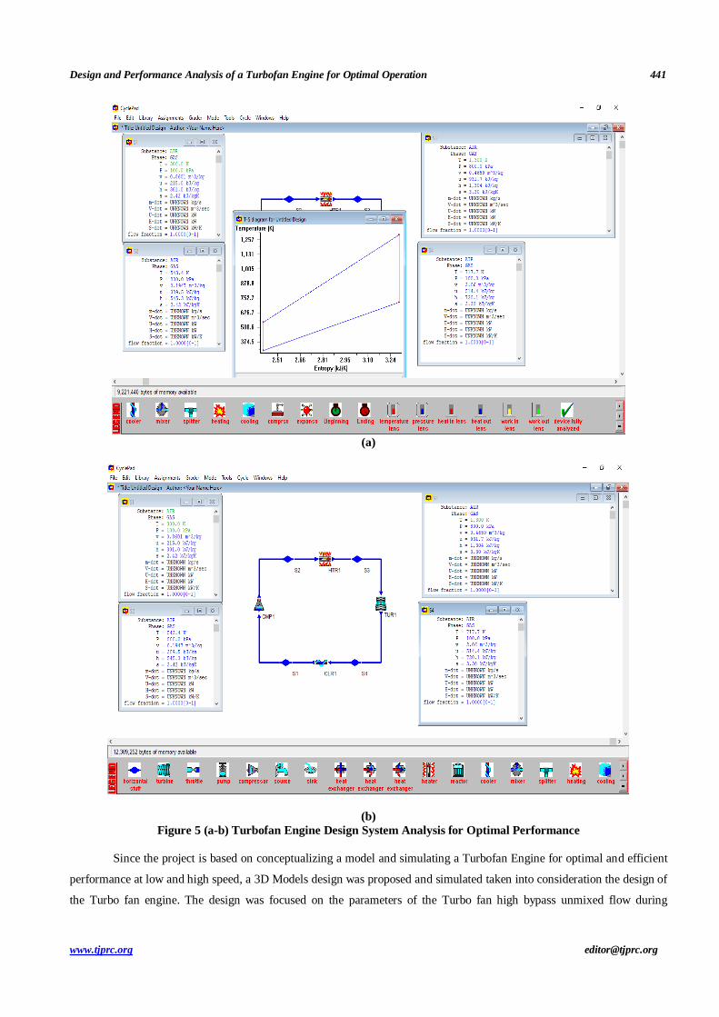
Design and Performance Analysis of a Turbofan Engine for Optimal Operation 441
www.tjprc.org [email protected]
(a)
(b)
Figure 5 (a-b) Turbofan Engine Design System Analysis for Optimal Performance
Since the project is based on conceptualizing a model and simulating a Turbofan Engine for optimal and efficient
performance at low and high speed, a 3D Models design was proposed and simulated taken into consideration the design of
the Turbo fan engine. The design was focused on the parameters of the Turbo fan high bypass unmixed flow during

442 P. B. Sob
Impact Factor (JCC): 9.6246 NAAS Rating: 3.11
operation. Since a Turbofan engine is the most modern variation of a basic Gas Turbine Engine, the major advantage is the
ability to produce a high thrust while maintaining good fuel efficiency. The design is built around the Gas Turbine core
which includes a Compressor, burner and a Turbine.
The concept of the turbo fan is to achieve more thrust with the same amount of fuel. That means Turbo fans are
likely to be fuel efficient during the operation. The thrust is derived from Newton’s second law F = ma and therefore,
thrust = Airflow x changes in velocity. This is achieved in such a way that air is captured at the inlet and is distributed into
two portions with regards to the bypass ratio. A portion of the air goes through the fan and travels through the bypass (Area
outside the engine) as shown in Figure 4 (a-b). The other portion of air passes through the fan and is transferred to the
compressor as shown in Figure 4(a-b). The compressor increases the pressure and temperature of the air as shown in Figure
5 (a) with a linear change in Entropy and Temperature during operation. As this takes place, more energy is added in the
combustion to have a more efficient process. The compressed air moves into the diffuser to slow down because it is
moving at a speed that it won’t be able to ignite. The diffuser slows the air down while maintaining the optimum pressure
and temperature as shown in Figure 5 (a). The air then moves to the combustion chamber where it is mixed with fuel for
the combustion process to occur. The hot air then moves to the turbines to reduce the pressure of the hot air and then out of
the exhaust nozzle. The process is being repeated throughout the cycles at optimal design performance as shown in Figure
5 (b). The design turbofan engine is reported to perform better at low speed and optimal engine performance. The flow
trajectory in the system was flowing more efficiently in the system as shown in Figure 4(a-b).
CONCLUSIONS AND RECOMMENDATIONS
The study was aimed at modelling and designing of a turbofan engine that will operate more efficiently even at low speed.
To achieve this objective, relevant parameters that impact the design performance of a turbofan engine was modelled for
optimal performance. The tool of solid work CFD simulation was used in simulation and the design performance was
revealed. It was shown that varying flow trajectory impacts the performance of the turbofan engine during operation. It was
also revealed that the combustion process plays a significant role in the engine performance which makes it difficult to
have optimal performance at low engine speed. It was also shown that varying ratio of air inflow in the system impacts
performance and the compressor have varying pressure and temperature which impacts the performance of the turbofan
engine. There is area of further research that will possibly help in increasing efficiency into their design such as further
investigation into flange design in order to create a flange that can integrate gasket material and ensure a proper, reliable
seal.
REFERENCES
1. http://www.airbus.com/en/aircraftfamilies/a380/
2. Rolls-Royce: Civil Aerospace
3. Rolls-Royce Trent 900 Engines Provide Power for First A380
4. http://en.wikipedia.org/wiki/Boeing_787
5. http://en.wikipedia.org/wiki/Rolls-Royce_Trent
6. http://en.wikipedia.org/wiki/Airbus_A380#Engines
7. Elements of gas turbine propulsion, Jack D. Mattingly, McGraw-Hill 1996

Design and Performance Analysis of a Turbofan Engine for Optimal Operation 443
www.tjprc.org [email protected]
8. DEBNATH, ANUPAM, BIDESH ROY, and ABHIJIT SINHA. "ASSESSMENT OF RNG k-ε, SST k-ω AND REYNOLDS
STRESS MODELS FOR NUMERICAL SIMULATION OF DLR SCRAMJET ENGINE." International Journal of Mechanical
and) Production Engineering Research and Development (IJMPERD) 9.4, Aug 2019, 1157-1166
9. Aerodynamics SFA, 1997- personal
10. Walters, E. A., Iden, S. M. and McCarthy, K., et al. INVENT Modeling, Simulation, Analysis, and Optimization. 48th AIAA
Aerospace Sciences Meeting, 4-7 January 2012. AIAA 2010-287.
11. SREEKANTH, N., and GR KRISHNA PRASAD YADAV. "EXPERIMENTAL EVALUATION OF PISTON USING ALUMINIUM
ALLOY (LM24) REINFORCED WITH SIC AND GRAPHITE." International Journal of Mechanical and Production
Engineering Research and Development (IJMPERD) ISSN 9.5, Oct 2019, 445–456
12. K. McCarthy, E. Walters, A. Heitzel., et al. Dynamic Thermal Management System Modeling of a More Electric Aircraft. SAE
Paper 2008-01-2886.
13. Dalbanjan, Manjunath S., and Niranjan Sarangi. "An Effect of Tip Clearance on Aero Performance in Axial Flow
Compressors for Aero Gas Turbine Engines." International Journal of Mechanical and Production Engineering Research and
Development (IJMPERD) 9.4, Aug 2019, 769 776.
14. Kamaraj, Jayachandran. Modeling and Simulation of Single Spool Jet Engine. University of Cincinnati Master's Thesis,
Cincinnati, Ohio. 2004.
15. Tong, Michael T., et al. Engine Conceptual Design Studies for a Hybrid Wing Body Aircraft. 2009 ASME Turbo Expo.,
Orlando, Florida. NASA/TM-2009-215680. ARL-TR-4719. GT2009-59568.
16. Reddy, P. RAVINDER, and P. ANJANI Devi. "Review on the advancements of additive manufacturing-4D and 5D
printing." Int J Mech Prod Eng Res Dev 8.4 (2018): 397-402.
17. Parker, Khary I. and Guo, Ten-Heui. Development of a Turbofan Engine Simulation in a Graphical Simulation Environment.
NASA Glenn Research Center. NASA/TM-2003-212543.
18. Rahman, Naveed U. and Whidborne, James F., Real-Time Transient Three Spool Turbofan Engine Simulation: A Hybrid
Approach. ASME Journal of Engineering for Gas Turbines and Power, 2009, Vol. 131, Issue 5, pp. 051602-1 - 051602-8.
19. Al-Hamdan, Qusai Z. and Ebaid, Munzer S. Y. Modeling and Simulation of a Gas Turbine Engine for Power Generation.
ASME Journal of Engineering for Gas Turbines and Power, 2006, Vol. 128, pp. 302 - 311.
20. Anliey, D.G., Mathieson, G.C.R. A Method of Performance Estimation for Axial-Flow Turbines. Aeronautical Research
Council Reports and Memoranda, 1957, R&M Number 2974.
21. Cohen, H., Rogers, G.F.C., Saravanamuttoo, H.I.H. Gas Turbine Theory 4th Edition. 1996, Longman, London.
22. . Kurzke, J. How to Get Component Maps for Aircraft Gas Turbine Performance Calculations. 1996, ASME paper 96-GT-164.
23. Cooke, James A, et al. Computational and experimental study of JP-8, a surrogate, and its components in counter flow
diffusion flames. Proceedings of the Combustion Institute, 2005, Vol. 30, pp. 439 - 446. 151
24. Thermofluids.net. Reactions: Heat of Formation Table, Table-G.1. [Online]
http://www.fing.edu.uy/if/mirror/TEST/testhome/Test/solve/basics/tables/tablesComb/formation.html.
25. Yarlagadda, Santosh. Performance Analysis of J85 Turbojet Engine Matching Thrust with Reduced Inlet Pressure to the
Compressor. The University of Toldeo Master's Thesis, Toledo, Ohio. 2010.
26. Kim, Sog-Kyun, Pilidis, Pericles and Yin, Junfei. Gas Turbine Dynamic Simulation Using Simulink. SAE Power Systems
444 P. B. Sob
Impact Factor (JCC): 9.6246 NAAS Rating: 3.11
Conference, San Diego, California, 2000, p. 359. SAE Paper 2000-01-3647.
27. Spittle, Peter. Gas Turbine Technology. Physics Education, 2003, Vol. 38, Number 6, pp. 504 - 511.
28. Rinaldi, G, et al. Dynamic pressure as a measure of gas turbine engine (GTE) performance. Measurement Science and
Technology, 2010, Vol. 21, Number 045201, pp. 1 - 9.
29. Massardo, Aristide F., Giusto, Cristiana and Ghiglino, Fabio. Stage performance influence on dynamic simulation of gas
turbine compressors. Aircraft Engineering and Aerospace Technology, 1997, Vol. 69, Number 6, pp. 543 - 554.
30. Crosa, G., et al. Heavy-Duty Gas Turbine Plant Aerothermodynamics Simulation Using Simulink. ASME Journal of
Engineering for Gas Turbines and Power, 1998, Vol. 120, pp. 550 - 556.
31. Ki, Jayoung, et al. Steady-State and Transient Performance Modeling of Smart UAV Propulsion System Using SIMULINK.
ASME Journal of Engineering for Gas Turbines and Power, 2009, Vol. 131, Issue 3, pp. 031702-2 - 031702-8.
32. Simon, Donald L. and Garg, Sanjay. A Systematic Approach for Model-Based Aircraft Engine Performance Estimation.
Infotech@Aerospace Conference, Seattle, Washington, 2009. NASA/TM-2010-216077. AIAA-2009-1872.
33. Huang, He, Spadaccini, Louis J and Sobel, David R. Fuel-Cooled Thermal Management for Advanced Aeroengines. ASME
Journal of Engineering for Gas Turbines and Power, 2004, Vol. 126, Issue 2, pp. 284 - 293.
34. Munson, Bruce R., Young, Donald F. and Okiishi, Theodore H. Fundamentals of Fluid Mechanics, Fifth Edition. John Wiley
& Sons, Inc., 2006. ISBN 0-471-67582-2.
35. Moran, Michael J. and Shapiro, Howard N. Fundamentals of Engineering Thermodynamics. John Wiley & Sons, Inc., 2008.
ISBN-13 978-0471-78735-8.