DESIGN AND MANUFACTURE OF MASTER PIECES OF ROLLER …
65
A Project Report on DESIGN AND MANUFACTURE OF MASTER PIECES OF ROLLER HOOK BY USING CNC TECHNIQUES AND SAND CASTING PROCESS Submitted to JAWAHARLAL NEHRU TECHNOLOGICAL UNIVERSITY HYDERABAD, HYDERABAD. In partial fulfillment of the requirements for the award of the degree of BACHELOR OF TECHNOLOGY In Mechanical Engineering By CHADA PRADEEP REDDY (138P1A0306) POLKAMPALLY PRANAY KUMAR (138P1A0326) T VINOD KUMAR (138P1A0333) KARNAVATH ANAND NAIK (138P1A0309) Under the Guidance of Mr. B.SHRAVAN KUMAR Asst. Professor AAR MAHAVEER ENGINEERING COLLEGE (Approved by AICTE, Affiliated to JNTUH, Hyderabad.) Vyasapuri, Bandlaguda, post: Keshavagiri, Hyderabad, 500005
Transcript of DESIGN AND MANUFACTURE OF MASTER PIECES OF ROLLER …

A Project Report on
DESIGN AND MANUFACTURE OF MASTER PIECES OF
ROLLER HOOK BY USING CNC TECHNIQUES AND SAND
CASTING PROCESS
Submitted to
JAWAHARLAL NEHRU TECHNOLOGICAL UNIVERSITY HYDERABAD, HYDERABAD.
In partial fulfillment of the requirements for the award of the degree of
BACHELOR OF TECHNOLOGY In
Mechanical Engineering
By
CHADA PRADEEP REDDY (138P1A0306)
POLKAMPALLY PRANAY KUMAR (138P1A0326)
T VINOD KUMAR (138P1A0333)
KARNAVATH ANAND NAIK (138P1A0309)
Under the Guidance of
Mr. B.SHRAVAN KUMAR
Asst. Professor
AAR MAHAVEER ENGINEERING COLLEGE
(Approved by AICTE, Affiliated to JNTUH, Hyderabad.)
Vyasapuri, Bandlaguda, post: Keshavagiri, Hyderabad, 500005
i
CERTIFICATE
This is to certify that the project entitled Design and Manufacture of
Master Pieces of Roller Hook by Using CNC Techniques and Sand Casting
Process submitted by Chada Pradeep Reddy, Polkampally Pranay Kumar,
T Vinod Kumar, Karnavath Anand Naik in the partial fulfillment of the
requirement for the award of B.Tech degree in Mechanical Engineering,
AAR Mahaveer Engineering College, Bandlaguda, is a record of the student’s
own work carried out by them under my supervision. The matter embodied in
this project report is original and has not been submitted for the award of any
other degree.
INTERNAL GUIDE
Mr. B. SHRAVAN KUMAR Mr. A.NARAYANA
Asst. Professor HOD (Mechanical)
EXTERNAL EXAMINAR

ii
DECLARATION
This is to certify that the Project entitled Design and Manufacture of
Master Pieces of Roller Hook by Using CNC Techniques and Sand Casting
Process. which is submitted by us in partial fulfillment of the requirement for the
award of B.Tech degree in Mechanical Engineering, AAR Mahaveer
Engineering College, Bandlaguda, comprises only our original work and due
acknowledgement has been made in the text to all other material used.
We, hereby, further declared that in case of any legal dispute in relation to
our B.Tech project, we shall be solely responsible for the same.
Date: Name of Students
Chada Pradeep Reddy (138P1A0306)
Polkampally Pranay Kumar (138P1A0326)
T Vinod Kumar (138P1A0333)
Karnavath Anand Naik (138P1A0309)

iii
ACKNOWLEDGEMENT
We are indeed very happy to greatly acknowledge the numerous
personalities involved in lending their help to make our project on “Design and
Manufacture of Master Pieces of Roller Hook by Using CNC Techniques
and Sand Casting Process” a successful one.
We take this opportunity to express our deep sense of gratitude to our
honorable Principal Dr. B.V.RAMANA MURTHY, for providing excellent
academic environment in the college that made this endeavors possible.
We have whole hearted administration and deep sense of gratitude to Mr.
B. Shravan Kumar, Asst. Professor of the Mechanical Engineering Department,
AAR Mahaveer Engineering College for his inspiration, valuable guidance,
encouragement, suggestions and overall help throughout, for successful
completion of this project.
We would like to express our sincere gratitude and thanks to all the faculty
members and the lab staff of the Department of Mechanical Engineering of AAR
Mahaveer Engineering College, who assisted or provided any kind of support
and encouragement in our project work.
Chada Pradeep Reddy (138P1A0306)
Polkampally Pranay Kumar (138P1A0326)
T Vinod Kumar (138P1A0333)
Karnavath Anand Naik (138P1A0309)

iv
ABSTRACT
Hooks are one of the repeatable components with mass production in lifting of
loads. For overhanging load pulley mechanisms are optimize to get maximum
lifting loads with less effort. Casting is a predominant and reliable process of
manufacturing components with low cost. For production purpose, better quality
of samples has to prepare by using CNC machining techniques. Hooks are
prepared by CNC machining Techniques and casting process. In this we increase
the performance of the load.
In the present project we are designing a hook, manufacture the masters
with CNC milling and casting masters will be submitted.

v
CONTENTS
Page No.
Title Page
Certificate i
Declaration ii
Acknowledgment iii
Abstract iv
Contents v-vi
List of Figures vii-viii
List of Tables ix
Chapter 1 Introduction 1
1.1 Sand Casting 1
1.2 Basic Steps In Making Sand Castings 2
Chapter 2 Literature Survey 4
2.1 About Casting 4
2.2 Types of Castings 5
2.3 Sand Casting 6
2.4 Important Considerations for Casting 7
Chapter 3 Types of Metals Used for Casting Production 14
3.1 Different Metals Used for Casting Production 14
3.2 Pattern Material Properties of Aluminium (AL) 15
3.3 Cast Iron Properties 18
3.4 Types of Cast Irons 18
Chapter 4 Introduction To CAD 22

vi
Chapter 5 Introduction To Unigraphics 24
5.1 Scientific Computing 24
5.2 Design Considerations of Roller Hook Pattern 25
Chapter 6 Introduction To Manufacturing 29
6.1 Introduction to CAM 29
6.2 Introduction to CNC Machining 30
6.3 Some of the CNC machines 31
6.4 Electric Discharge Machining 32
6.5 CNC Machine Programming 33
Chapter 7 Introduction To Program 34
7.1 G-codes 34
7.2 M-codes 36
7.3 Computer Numerical Control Machine 37
7.4 Tooling 38
Chapter 8 Introduction To DELCAM 40
8.1 Raw Material Specifications 40
8.2 Pattern Manufacturing Process 41
8.3 Generation of CNC Program for Tool Paths 45
8.4 Finishing Tool Path 48
8.5 Results 50
Conclusion 53
References 54

vii
LIST OF FIGURES
Fig. No. Particulars Page No
1.1 schematic showing steps of the sand casting process 3
2.1 work flow in typical sand-casting foundries 6
2.2 taper in design 7
2.3 design components of a mould showing chaplets 8
2.4 Shell mould casting 9
2.5 hot and cold chamber die casting 12
2.6 centrifugal casting schematic 13
5.1 2D drawing in sketcher 25
5.2 3D development by extruding 25
5.3 2d-layout 26
5.4 3d-layout 26
5.5 direction of usage 27
5.6 pattern layout 28
7.1 five-axis machining center with rotating table and
computer interface 37
7.2 high speed steel with cobalt end mills used for cutting
operations in a milling machine 38
7.3 a CAT-40 tool holder 39
7.4 a boring head on a Morse taper shank 39

viii
8.1 raw material actors 41
8.2 DELCAM starting 41
8.3 file importing 41
8.4 work plane and raw material block creation 42
8.5 tool path generation 42
8.6 creating tool path for finishing 43
8.7 surfacing tool path 43
8.8 tool path simulations 44
8.9 master print machining 51
8.10 assembly of hook with masters 51
8.11 core box assembly components 52

ix
LIST OF TABLES
Table No. Page No
2.1 Types of casting, advantages, disadvantages and examples 5
3.1 Different metals used for casting production 15
3.2 Various shapes and sizes of Aluminium 16

Design & Manufacture of Master Pieces of Roller Hook By CNC Techniques & Sand Casting
Dept. of Mechanical Engineering, AARM Hyderabad Page 1
CHAPTER-1
INTRODUCTION
Housing is one of the accurate components to keep the bearing reliability and safety.
A new generation of bearing protectors is now available that can help maintain lubricant
cleanliness, prevent loss of lubricants, and prolong the life of your rotating equipment.
Depending upon the design of a shaft or housing, the shaft may be influenced by an unbalanced
load or other factors which can then cause large fluctuations in bearing efficiency. For this
reason, it is necessary to pay attention to the following when designing shaft and housing:
Bearing arrangement selection; most effective fixing method for bearing arrangement
Selection of shoulder height and fillet radius of housing and shaft.
Shape precision and dimensions of fitting; area run out tolerance of shoulder.
Machining precision and mounting error of housing and shaft suitable for allowable alignment
angle and inclination of bearing.
1.1 Sand Casting
Sand casting, also known as sand moulded casting, is a metal casting process characterized by
using sand as the mould material. It is relatively cheap and sufficiently refractory even for steel
foundry use. A suitable bonding agent (usually clay) is mixed or occurs with the sand. The
mixture is moistened with water to develop strength and plasticity of the clay and to make the
aggregate suitable for moulding. The term "sand casting" can also refer to a casting produced via
the sand casting process. Sand castings are produced in specialized factories called foundries.
Over 70% of all metal castings are produced via a sand casting process.
Molds made of sand are relatively cheap, and sufficiently refractory even for steel
foundry use. In addition to the sand, a suitable bonding agent (usually clay) is mixed or occurs
with the sand.
The mixture is moistened, typically with water, but sometimes with other substances, to
develop the strength and plasticity of the clay and to make the aggregate suitable for molding.
The sand is typically contained in a system of frames or mold boxes known as a flask.
The mold cavities and gate system are created by compacting the sand around models,
or patterns, or carved directly into the sand.

Design & Manufacture of Master Pieces of Roller Hook By CNC Techniques & Sand Casting
Dept. of Mechanical Engineering, AARM Hyderabad Page 2
1.2 Basic Steps In Making Sand Castings
The basic steps involved in making sand castings are:
1. Patternmaking: Patterns are required to make moulds. The mould is made by packing
moulding sand around the pattern. The mould is usually made in two parts so that the pattern
can be withdrawn.
In horizontal moulding, the top half is called the cope, and the bottom half is called the
drag.
In vertical moulding, the leading half of the mould is called the swing, and the back half
is called the ram.
When the patterns withdrawn from the moulding material (sand or other), the imprint of
the pattern provides the cavity when the mould parts are brought together. The mould
cavity, together with any internal cores as required, is ultimately filled with molten metal
to form the casting.
2. If the casting is to be hollow, additional patterns, referred to as core boxes, are needed to
shape the sand forms, or cores, that are placed in the mould cavity to form the interior surfaces
and sometimes the external surfaces as well of the casting. Thus the void between the mould and
core eventually becomes the casting.
3. Moulding: is the operation necessary to prepare a mould for receiving the metal. It consists of
ramming sand around the pattern placed in support, or flask, removing the pattern, setting cores
in place, and creating the gating/feeding system to direct the metal into the mould cavity created
by the pattern, either by cutting it into the mould by hand or by including it on the pattern, which
is most commonly used.
4. Melting and pouring are the processes of preparing molten metal of the proper composition
and temperature and pouring this into the mould from transfer ladles.
5. Cleaning includes all the operations required to remove the gates and risers that constitute the
gating/feeding system and to remove the adhering sand, scale, parting fins, and other foreign
material that must be removed before the casting is ready for shipment or other processing.
Paths for the entrance of metal into the mold cavity constitute the runner system and
include the sprue, various feeders which maintain a good metal 'feed', and in-gates which attach
the runner system to the casting cavity.
Gas and steam generated during casting exit through the permeable sand or
via risers, which are added either in the pattern itself, or as separate pieces.

Design & Manufacture of Master Pieces of Roller Hook By CNC Techniques & Sand Casting
Dept. of Mechanical Engineering, AARM Hyderabad Page 3
Fig: 1.1 schematic showing steps of the sand casting process

Design & Manufacture of Master Pieces of Roller Hook By CNC Techniques & Sand Casting
Dept. of Mechanical Engineering, AARM Hyderabad Page 4
CHAPTER-2
LITERATURE SURVEY
2.1 About Casting
2.1.1 Casting methods
Metal casting process begins by creating a mould, which is the ‘reverse’ shape of the part we need. The mould is made from a refractory material, for example, sand. The metal is heated in an
oven until it melts, and the molten metal is poured into the mould cavity.
The liquid takes the shape of cavity, which is the shape of the part. It is cooled until it
solidifies. Finally, the solidified metal part is removed from the mould.
A large number of metal components in designs we use every day are made by casting. The
reasons for this include:
(a) Casting can produce very complex geometry parts with internal cavities and hollow sections.
(b) It can be used to make small to very large size parts
(c) It is economical, with very little wastage: the extra metal in each casting is re-melted and re
used
(d) Cast metal is isotropic – it has the same physical/mechanical properties along a ny direction.
2.1.2 Common Examples
The solidified part is also known as a casting, which is ejected or broken out of the mold to
complete the process. Casting materials are usually metals or various cold setting materials that
cure after mixing two or more components together; examples are epoxy, concrete, plaster and
clay.
Door Handles, Locks, The outer casing or housing for motors, pumps, etc., wheels of
many cars. Casting is also heavily used in the toy industry to make parts, e.g. toy cars, planes,
and so on.

Design & Manufacture of Master Pieces of Roller Hook By CNC Techniques & Sand Casting
Dept. of Mechanical Engineering, AARM Hyderabad Page 5
2.2 Types of Castings
Summarizes different types of castings, their advantages, disadvantages and examples.
Process Advantages Disadvantages Examples
Sand Wide range material
sizes, shapes ,low
cost
Poor finishing ,wide
tolerance
Engine blocks and
cylinder heads
Shell mould Better accuracy,
higher production
rate
Limited part size Connect rods ,gear
housings
Expandable patterns Wide range of metals Pattern have low
strength
Cylinder heads, break
components
Plaster mould Complex shapes
,high accuracy ,good
finishing
Non-ferrous metals
low production rate
Prototype of
mechanical
components
Ceramic mould Complex shape ,high
accuracy
Small sizes Impellers ,induction
mould tooling
Permanent mould Good finishing ,low
porosity ,high
production rate
Costly moulds
,simpler shapes only
Gears, gear housings
Die Excellent
dimensional ,high
production rate
Costly moulds ,small
parts, non
Ferrous metals
Precession gears
,camera bodies ,car
wheels
Centrifugal Large cylindrical
parts ,good quality
Expensive or limited
shapes
Pipes boilers ,fly
wheels
Table: 2.1 types of casting, advantages, disadvantages and examples

Design & Manufacture of Master Pieces of Roller Hook By CNC Techniques & Sand Casting
Dept. of Mechanical Engineering, AARM Hyderabad Page 6
2.3 Sand casting
Fig: 2.1 work flow in typical sand-casting foundries

Design & Manufacture of Master Pieces of Roller Hook By CNC Techniques & Sand Casting
Dept. of Mechanical Engineering, AARM Hyderabad Page 7
Sand casting uses natural or synthetic sand (lake sand) which is mostly a refractory material
called silica (SiO2). The sand grains must be small enough so that it can be packed densely;
however, the grains must be large enough to allow gasses formed during the metal pouring to
escape through the pores. Larger sized moulds use green sand (mixture of sand, clay and some
water). Sand can be re-used, and excess metal poured is cut-off and re-used also.
2.4 Important considerations for casting
(a) How do we make the pattern?
Usually craftsmen will carve the part shape by hand and machines to the exact size.
(b) Why is the pattern not exactly identical to the part shape?
- You only need to make the outer surfaces with the pattern; the inner surfaces are made by
the core
- You need to allow for the shrinkage of the casting after the metal solidifies
(c) If you intersect the plane formed by the mating surfaces of the drag and cope with the cast
part, you will get a cross-section of the part. The outer part of the outline of this cross section is
called the parting line. The design of the mould is done by first determining the parting line
(why?)
(d) In order to avoid damaging the surface of the mould when removing the pattern and the
wood-pieces for the vents, pouring cup and spur, risers etc., it is important to incline the vertical
surfaces of the part geometry. This (slight) inclination is called a taper. If you know that your
part will be made by casting, you should taper the surfaces in the original part design.
Fig: 2.2 taper in design

Design & Manufacture of Master Pieces of Roller Hook By CNC Techniques & Sand Casting
Dept. of Mechanical Engineering, AARM Hyderabad Page 8
(e) The core is held in position by supporting geometry called core prints (see figure below). If
the design is such that there is insufficient support to hold the core in position, then metal
supports called chaplets are used. The chaplets will be embedded inside the final part.
Fig: 2.3 design components of a mould showing chaplets
(f) After the casting is obtained, it must be cleaned using air-jet or sand blasting
(g) Finally, the extra metal near the gate, risers and vents must be cut off, and critical surfaces
are machined to achieve proper surface finish and tolerance.
2.4.1 Shell-mould casting
Shell-mould casting yields better surface quality and tolerances. The process is described
as follows:
The 2-piece pattern is made of metal (e.g. aluminium or steel), it is heated to between
175°C-370°C, and coated with a lubricant, e.g. silicone spray.
Each heated half-pattern is covered with a mixture of sand and a thermo set resin/epoxy
binder. The binder glues a layer of sand to the pattern, forming a shell. The process may
be repeated to get a thicker shell.
The assembly is baked to cure it.
The patterns are removed, and the two half-shells joined together to form the mould;
metal is poured into the mould.
When the metal solidifies, the shell is broken to get the part.

Design & Manufacture of Master Pieces of Roller Hook By CNC Techniques & Sand Casting
Dept. of Mechanical Engineering, AARM Hyderabad Page 9
Fig: 2.4 shell mould casting
2.4.2 Expendable-pattern casting
The pattern used in this process is made from polystyrene (this is the light, white packaging
material which is used to pack electronics inside the boxes). Polystyrene foam is 95% air
bubbles, and the material itself evaporates when the liquid metal is poured on it.
The pattern itself is made by moulding – the polystyrene beads and pentane are put inside an
aluminium mould, and heated; it expands to fill the mould, and takes the shape of the cavity. The
pattern is removed, and used for the casting process, as follows:
- The pattern is dipped in slurry of water and clay (or other refractory grains); it is dried to get a
hard shell around the pattern.
- The shell-covered pattern is placed in a container with sand for support, and liquid metal is
poured from a hole on top.
- The foam evaporates as the metal fills the shell; upon cooling and solidification, the part is
removed by breaking the shell.
The process is useful since it is very cheap, and yields good surface finish and complex
geometry. There are no runners, risers, gating or parting lines – thus the design process is
simplified. The process is used to manufacture crank-shafts for engines, aluminium engine
blocks, manifolds etc.

Design & Manufacture of Master Pieces of Roller Hook By CNC Techniques & Sand Casting
Dept. of Mechanical Engineering, AARM Hyderabad Page 10
2.4.3 Plaster-mould casting
The mould is made by mixing plaster of Paris (CaSO4) with talc and silica flour; this is a fine
white powder, which, when mixed with water gets a clay-like consistency and can be shaped
around the pattern (it is the same material used to make casts for people if they fracture a bone).
The plaster cast can be finished to yield very good surface finish and dimensional accuracy.
However, it is relatively soft and not strong enough at temperature above 1200°C, so this method
is mainly used to make castings from non-ferrous metals, e.g. zinc, copper, aluminium, and
magnesium.
Since plaster has lower thermal conductivity, the casting cools slowly, and therefore has more
uniform grain structure (i.e. less war page, less residual stresses).
2.4.4 Ceramic mould casting
Similar to plaster-mould casting, except that ceramic material is used (e.g. silica or powdered
Zircon ZrSiO4). Ceramics are refractory (e.g. the clay hotpot used in Chinese restaurants to cook
some dishes), and also have higher strength that plaster.
- The ceramic slurry forms a shell over the pattern;
- It is dried in a low temperature oven, and the pattern is removed
- Then it is backed by clay for strength, and baked in a high temperature oven to burn off any
volatile substances.
- The metal is cast same as in plaster casting.
This process can be used to make very good quality castings of steel or even stainless steel; it is
used for parts such as impellor blades (for turbines, pumps, or rotors for motor-boats).
2.4.5 Permanent mould casting
Here, the two halves of the mould are made of metal, usually cast iron, steel, or refractory alloys.
The cavity, including the runners and gating system are machined into the mould halves. For
hollow parts, either permanent cores (made of metal) or sand-bonded ones may be used,
depending on whether the core can be extracted from the part without damage after casting. The
surface of the mould is coated with clay or other hard refractory material – this improves the life
of the mould. Before moulding, the surface is covered with a spray of graphite or silica, which
acts as a lubricant. This has two purposes – it improves the flow of the liquid metal, and it allows
the cast part to be withdrawn from the mould more easily. The process can be automated, and
therefore yields high throughput rates. Also, it produces very good tolerance and surface finish.
It is commonly used for producing pistons used in car engines, gear blanks, cylinder heads, and
other parts made of low melting point metals, e.g. copper, bronze, aluminium, magnesium, etc.

Design & Manufacture of Master Pieces of Roller Hook By CNC Techniques & Sand Casting
Dept. of Mechanical Engineering, AARM Hyderabad Page 11
2.4.6 Die casting
Die casting is a very commonly used type of permanent mould casting process. It is used for
producing many components of home appliances (e.g. rice cookers, stoves, fans, washing and
drying machines, fridges), motors, toys and hand-tools – since Pearl river delta is a largest
manufacturer of such products in the world, this technology is used by many HK-based
companies. Surface finish and tolerance of die cast parts is so good that there is almost no post-
processing required. Die casting moulds are expensive, and require significant lead time to
fabricate; they are commonly called dies. There are two common types of die casting: hot- and
cold-chamber die casting.
• In a hot chamber process (used for Zinc alloys, magnesium) the pressure chamber connected to the die cavity is filled permanently in the molten metal.
The basic cycle of operation is as follows: (i) die is closed and gooseneck cylinder is
filled with molten metal; (ii) plunger pushes molten metal through gooseneck passage and nozzle
and into the die cavity; metal is held under pressure until it solidifies; (iii) die opens and cores, if
any, are retracted; casting stays in ejector die; plunger returns, pulling molten metal back through
nozzle and gooseneck; (iv) ejector pins push casting out of ejector die. As plunger uncovers inlet
hole, molten metal refills gooseneck cylinder.
The hot chamber process is used for metals that (a) have low melting points and (b) do
not alloy with the die material, steel; common examples are tin, zinc, and lead.
• In a cold chamber process, the molten metal is poured into the cold chamber in each cycle. The operating cycle is (i) Die is closed and molten metal is ladled into the cold chamber
cylinder; (ii) plunger pushes molten metal into die cavity; the metal is held under high pressure
until it solidifies; (iii) die opens and plunger follows to push the solidified slug from the cylinder,
if there are cores, they are retracted away; (iv) ejector pins push casting off ejector die and
plunger returns to original position. This process is particularly useful for high melting point
metals such as Aluminium, and Copper (and its alloys).

Design & Manufacture of Master Pieces of Roller Hook By CNC Techniques & Sand Casting
Dept. of Mechanical Engineering, AARM Hyderabad Page 12
Fig: 2.5 hot and cold chamber die casting

Design & Manufacture of Master Pieces of Roller Hook By CNC Techniques & Sand Casting
Dept. of Mechanical Engineering, AARM Hyderabad Page 13
2.4.7 Centrifugal casting
Centrifugal casting uses a permanent mould that is rotated about its axis at a speed between 300
to 3000 rpm as the molten metal is poured. Centrifugal forces cause the metal to be pushed out
towards the mould walls, where it solidifies after cooling. Parts cast in this method have a fine
grain microstructure, which is resistant to atmospheric corrosion; hence this method has been
used to manufacture pipes. Since metal is heavier than impurities, most of the impurities and
inclusions are closer to the inner diameter and can be machined away.
Surface finish along the inner diameter is also much worse than along the outer surface
Fig: 2.6 centrifugal casting schematic
Design & Manufacture of Master Pieces of Roller Hook By CNC Techniques & Sand Casting
Dept. of Mechanical Engineering, AARM Hyderabad Page 14
CHAPTER-3
TYPES OF METALS USED FOR CASTING PRODUCTION
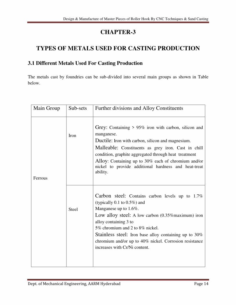
3.1 Different Metals Used For Casting Production
The metals cast by foundries can be sub-divided into several main groups as shown in Table
below.
Main Group Sub-sets Further divisions and Alloy Constituents
Ferrous
Iron
Grey: Containing > 95% iron with carbon, silicon and
manganese.
Ductile: Iron with carbon, silicon and magnesium.
Malleable: Constituents as grey iron. Cast in chill
condition, graphite aggregated through heat treatment
Alloy: Containing up to 30% each of chromium and/or
nickel to provide additional hardness and heat-treat
ability.
Steel
Carbon steel: Contains carbon levels up to 1.7%
(typically 0.1 to 0.5%) and
Manganese up to 1.6%.
Low alloy steel: A low carbon (0.35%maximum) iron
alloy containing 3 to
5% chromium and 2 to 8% nickel.
Stainless steel: Iron base alloy containing up to 30%
chromium and/or up to 40% nickel. Corrosion resistance
increases with Cr/Ni content.

Design & Manufacture of Master Pieces of Roller Hook By CNC Techniques & Sand Casting
Dept. of Mechanical Engineering, AARM Hyderabad Page 15
Non-ferrous
Aluminium
Various alloys usually containing silicon, copper and/or
magnesium.
Copper
Pure copper: > 99% pure
Brass: an alloy of copper and zinc (up to 45%),
sometimes with up to 2% lead and 1% tin.
Bronze: an alloy of copper and tin (up to 12%).
Variations: leaded bronze (9 to 22% lead), gun metal (3
to 5% lead & 2 to 8% zinc), aluminium bronze (with 6 to
9% aluminium, 0 to 5% nickel, 0.5 to 5% iron), phosphor
bronze.
Zinc
Zinc-based alloys with up to 4% aluminium and trace
amounts of copper, magnesium, etc.
Super
alloys
Nickel or cobalt-based alloys in combination with
chromium, iron, manganese, molybdenum, etc.
Magnesium
Magnesium alloyed with aluminium, zinc and thorium.
Other metals can be added in trace amounts.
Titanium
Pure titanium: > 99% pure α/β alloys with aluminium,
vanadium, zinc, molybdenum and zirconium.
Table: 3.1 different metals used for casting production
3.2 Pattern Material Properties of Aluminium (AL)
Aluminium is the most commonly used and commercially available metal. Its light weight and
high strength-to-weight ratio make it a good choice for everything from aircraft to flashlights to
jigs to just about anything else you can make out of metal. Pure aluminium, primarily seen in the
1xxx series of wrought aluminium alloys, has little strength, but possesses high electrical
conductivity, reflectivity, and corrosion resistance. For this reason, a wide variety of aluminium
alloys have been developed.

Design & Manufacture of Master Pieces of Roller Hook By CNC Techniques & Sand Casting
Dept. of Mechanical Engineering, AARM Hyderabad Page 16
Here is six alloys of aluminium in various shapes and sizes:
2011 Aluminium Available in Hex, Round
2024 Aluminium Available in Plate, Rectangle, Round, Sheet, Square, Tube
5052 Aluminium Available in Sheet
6061 Aluminium Available in Angle, Channel, I-Beam, Pipe, Plate, Rectangle, Round,
Sheet, Square, Tube
6063 Aluminium Available in Angle, Channel, Rectangle Tube, Square Tube
7075 Aluminium Available in Plate, Round, Sheet
Table: 3.2 various shapes and sizes of aluminium
2011 Aluminium
2011(AL) is the most machinable of the commonly available aluminium alloys.
Machining this alloy can produce excellent surface finishes on your product, and small,
broken chips.
Weldability, strength, and anodizing response are all rated as average at best, and this
alloy does not have a high degree of corrosion resistance.
If the ability to make your part quickly is important to you, and strength is not the
primary desire, 2011(AL) represents a good choice if you're using aluminium.
2024 Aluminium
Copper is the main alloying ingredient in 2024(AL).
It is very strong compared to most aluminium alloys, and has average machinability, but
the copper component of this alloy makes it susceptible to corrosion (many items in this
alloy are produced with a clad surface to protect the underlying material.)
In addition, 2024(AL) is not considered to be wieldable.
Finally, the fatigue resistance of 2024(AL) make it a primary choice when the
application is expected to be under stress or strain for prolonged periods. It is commonly
used in aerospace applications.

Design & Manufacture of Master Pieces of Roller Hook By CNC Techniques & Sand Casting
Dept. of Mechanical Engineering, AARM Hyderabad Page 17
5052 Aluminium
5052(AL). is the alloy most suited to forming operations, with good workability and
higher strength than that of the 1100(AL). or 3003(AL). Alloys that are commercially
available.
5052(AL). is not heat-treatable, but is stronger than most of the 5xxx series of alloys.
5052(AL). has very good corrosion resistance, and can be easily welded.
5052(AL). is not a good choice for extensive machining operations, as it has only a fair
machinability rating.
6061 Aluminium
6061 Aluminium is, by most any measure, the most commonly used aluminium alloy.
It is specified in most any application due to its strength, heat treatability, comparatively
easy machining, and weldability.
If that were not enough, it is also capable of being anodized, adding a layer of protection
for finished parts.
The main alloy ingredients of 6061 aluminium are magnesium and silicon.
6063 Aluminium
6063 is often called architectural aluminium for two reasons
First, it has a surface finish that is far smoother than the other commercially available
alloys.
Second, its strength is significantly less (roughly half the strength of 6061), making it
suited for applications where strength is not the foremost consideration.
6063 is rated as "Good" for forming and cold working operations, "Excellent" for
anodizing, and "Fair" for machining.
7075 Aluminium
7075 is "aircraft grade" aluminium.
Its principal alloying ingredients are Zinc and copper, which make it one of the highest-
strength aluminium alloys that are available. In fact, its typical strength in the T6 temper
is higher than most mild steels.
7075 also has average-to-good ratings for machinability, corrosion resistance, and
anodizing response. Like 2024, however, it is not considered to be weldable.

Design & Manufacture of Master Pieces of Roller Hook By CNC Techniques & Sand Casting
Dept. of Mechanical Engineering, AARM Hyderabad Page 18
3.3 Cast Iron Properties
Cast iron is iron or a ferrous alloy which has been heated until it liquefies, and is then
poured into a mould to solidify. It is usually made from pig iron. The alloy constituents affect its
colour when fractured: white cast iron has carbide impurities which allow cracks to pass straight
through Grey cast iron has graphitic flakes which deflect a passing crack and initiate countless
new cracks as the material breaks.
Carbon (C) and silicon (Si) are the main alloying elements, with the amount ranging from 2.1–4 wt% and 1–3 wt%, respectively. Iron alloys with less carbon content are known as steel. While
this technically makes these base alloys ternary Fe–C–Si alloys, the principle of cast iron
solidification is understood from the binary iron–carbon phase diagram. Since the compositions
of most cast irons are around the eutectic point of the iron–carbon system, the melting
temperatures closely correlate, usually ranging from 1,150 to 1,200 °C (2,100 to 2,190 °F),
which is about 300 °C (572 °F) lower than the melting point of pure iron.
Cast iron tends to be brittle, except for malleable cast irons. With its relatively low melting point,
good fluidity, castability, excellent machinability, resistance to deformation and wear resistance,
cast irons have become an engineering material with a wide range of applications and are used in
pipes, machines and automotive industry parts, such as cylinder heads (declining usage), cylinder
blocks and gearbox cases. It is resistant to destruction and weakening by oxidation
Cast iron is made by re-melting pig iron, often along with substantial quantities of scrap iron,
scrap steel, lime stone, carbon (coke) and taking various steps to remove undesirable
contaminants. Phosphorus and sulphur may be burnt out of the molten iron, but this also burns
out the carbon, which must be replaced. Depending on the application, carbon and silicon
content are adjusted to the desired levels, which may be anywhere from 2–3.5% and 1–3%
respectively. Other elements are then added to the melt before the final form is produced by
casting. Iron is sometimes melted in a special type of blast furnace known as a cupola, but more
often melted in electric induction furnaces or electric arc furnaces.[citation needed]
After melting is
complete, the molten iron is poured into a holding furnace or ladle.
3.4 Types of Cast Iron
Cast iron's properties are changed by adding various alloying elements, or alloyants. Next to
carbon, silicon is the most important alloyant because it forces carbon out of solution. Instead the
carbon forms graphite which results in a softer iron, reduces shrinkage, lowers strength, and
decreases density. Sulphur, when present, forms iron sulphide. , which prevents the formation of
graphite and increases hardness. The problem with sulphur is that it makes molten cast iron
sluggish, which causes short run defects. To counter the effects of sulphur, manganese is added
Design & Manufacture of Master Pieces of Roller Hook By CNC Techniques & Sand Casting
Dept. of Mechanical Engineering, AARM Hyderabad Page 19
because the two form into manganese sulphide. instead of iron sulphide. The manganese
sulphide is lighter than the melt so it tends to float out of the melt and into the slag. The amount
of manganese required to neutralize sulphur is 1.7 × sulphur content + 0.3%. If more than this
amount of manganese is added, then manganese carbide forms, which increases hardness and
chilling, except in grey iron, where up to 1% of manganese increases strength and density.
Nickel is one of the most common alloying elements because it refines the pearlite and graphite
structure, improves toughness, and evens out hardness differences between section thicknesses.
Chromium is added in small amounts to the ladle to reduce free graphite, produce chill, and
because it is a powerful carbide stabilizer; nickel is often added in conjunction. A small amount
of tin can be added as a substitute for 0.5% chromium. Copper is added in the ladle or in the
furnace, on the order of 0.5–2.5%, to decrease chill, refine graphite, and increase fluidity.
Molybdenum is added on the order of 0.3–1% to increase chill and refine the graphite and
pearlite structure; it is often added in conjunction with nickel, copper, and chromium to form
high strength irons. Titanium is added as a degasser and deoxidizer, but it also increases fluidity.
0.15–0.5% vanadium are added to cast iron to stabilize cementite, increase hardness, and
increase resistance to wear and heat. 0.1–0.3% zirconium helps to form graphite, deoxidize, and
increase fluidity.
In malleable iron melts, bismuth is added, on the scale of 0.002–0.01%, to increase how much
silicon can be added. In white iron, boron is added to aid in the production of malleable iron; it
also reduces the coarsening effect of bismuth
3.4.1 Grey cast iron
Grey cast iron is characterised by its graphitic microstructure, which causes fractures of the
material to have a grey appearance. It is the most commonly used cast iron and the most widely
used cast material based on weight. Most cast irons have a chemical composition of 2.5–4.0%
carbon, 1–3% silicon, and the remainder is iron. Grey cast iron has less tensile strength and
shock resistance than steel, but its compressive strength is comparable to low and medium
carbon steel.
3.4.2 White cast iron
It is the cast iron that displays white fractured surface due to the presence of cementite. With a
lower silicon content (graphitizing agent) and faster cooling rate, the carbon in white cast iron
precipitates out of the melt as the metastable phase cementite, Fe3C, rather than graphite.
The cementite which precipitates from the melt forms as relatively large particles,
usually in a eutectic mixture, where the other phase is austenite (which on cooling might
transform to martensite). These eutectic carbides are much too large to provide precipitation
hardening (as in some steels, where cementite precipitates might inhibit plastic deformation by
impeding the movement of dislocations through the ferrite matrix).
Design & Manufacture of Master Pieces of Roller Hook By CNC Techniques & Sand Casting
Dept. of Mechanical Engineering, AARM Hyderabad Page 20
Rather, they increase the bulk hardness of the cast iron simply by virtue of their own
very high hardness and their substantial volume fraction, such that the bulk hardness can be
approximated by a rule of mixtures. In any case, they offer hardness at the expense of toughness.
Since carbide makes up a large fraction of the material, white cast iron could reasonably be
classified as a cermet.
White iron is too brittle for use in many structural components, but with good
hardness and abrasion resistance and relatively low cost, it finds use in such applications as the
wear surfaces (impeller and volute) of slurry pumps, shell liners and lifter bars in ball mills and
autogenous grinding mills, balls and rings in coal pulverisers, and the teeth of a backhoe's
digging bucket (although cast medium-carbon martensitic steel is more common for this
application).
It is difficult to cool thick castings fast enough to solidify the melt as white cast iron all the way
through. However, rapid cooling can be used to solidify a shell of white cast iron, after which the
remainder cools more slowly to form a core of grey cast iron. The resulting casting, called a
chilled casting, has the benefits of a hard surface and a somewhat tougher interior.
High-chromium white iron alloys allow massive castings (for example, a 10-tonne impeller) to
be sand cast, i.e., a high cooling rate is not required, as well as providing impressive abrasion
resistance. These high-chromium alloys attribute their superior hardness to the presence of
chromium carbides.
The main form of these carbides are the eutectic or primary M7C3 carbides, where
"M" represents iron or chromium and can vary depending on the alloy's composition. The
eutectic carbides form as bundles of hollow hexagonal rods and grow perpendicular to the
hexagonal basal plane. The hardness of these carbides are within the range of 1500-1800HV
3.4.3 Malleable cast iron
Malleable iron starts as a white iron casting that is then heat treated at about 900 °C (1,650 °F).
Graphite separates out much more slowly in this case, so that surface tension has time to form it
into spheroidal particles rather than flakes. Due to their lower aspect ratio, spheroids are
relatively short and far from one another, and have a lower cross section vis-a-vis a propagating
crack or phonon.
They also have blunt boundaries, as opposed to flakes, which alleviates the stress
concentration problems faced by grey cast iron. In general, the properties of malleable cast iron
are more like mild steel.
There is a limit to how large a part can be cast in malleable iron, since it is made from
white cast iron.

Design & Manufacture of Master Pieces of Roller Hook By CNC Techniques & Sand Casting
Dept. of Mechanical Engineering, AARM Hyderabad Page 21
3.4.4 Ductile cast iron
A more recent development is nodular or ductile cast iron. Tiny amounts of magnesium or
cerium added to these alloys slow down the growth of graphite precipitates by bonding to the
edges of the graphite planes. Along with careful control of other elements and timing, this allows
the carbon to separate as spheroidal particles as the material solidifies. The properties are similar
to malleable iron, but parts can be cast with larger sections.
Ductile iron is not a single material but part of a group of materials which can be
produced with a wide range of properties through control of their microstructure. The common
defining characteristic of this group of materials is the shape of the graphite. In ductile irons,
graphite is in the form of nodules rather than flakes as in grey iron. Whereas sharp graphite
flakes create stress concentration points within the metal matrix, rounded nodules inhibit the
creation of cracks, thus providing the enhanced ductility that gives the alloy its name.
Nodule formation is achieved by adding nodulizing elements, most
commonly magnesium (magnesium boils at 1100 °C and iron melts at 1500 °C) and, less often
now, cerium (usually in the form of mischmetal). Tellurium has also been used. Yttrium, often a
component of mischmetal, has also been studied as a possible nodulizer.
Austempered Ductile Iron (ADI) was discovered in the 1950s but was commercialized
and achieved success only some years later. In ADI, the metallurgical structure is manipulated
through a sophisticated heat treating process. The "aus" portion of the name refers to austenite.

Design & Manufacture of Master Pieces of Roller Hook By CNC Techniques & Sand Casting
Dept. of Mechanical Engineering, AARM Hyderabad Page 22
CHAPTER-4
INRODUCTION TO CAD
Computer-aided design (CAD) is the use of computer systems to assist in the creation,
modification, analysis, or optimization of a design. CAD software is used to increase the
productivity of the designer, improve the quality of design, improve communications through
documentation, and to create a database for manufacturing. CAD output is often in the form of
electronic files for print, machining, or other manufacturing operations.
Computer-aided design is used in many fields. Its use in designing electronic systems is
known as Electronic Design Automation, or EDA. In mechanical design it is known
as Mechanical Design Automation (MDA) or computer-aided drafting (CAD), which includes
the process of creating a technical drawing with the use of computer software.
CAD software for mechanical design uses either vector-based graphics to depict the
objects of traditional drafting, or may also produce raster graphics showing the overall
appearance of designed objects. However, it involves more than just shapes. As in the
manual drafting of technical and engineering drawings, the output of CAD must convey
information, such as materials, processes, dimensions, and tolerances, according to application-
specific conventions.
CAD may be used to design curves and figures in two-dimensional (2D) space; or curves,
surfaces, and solids in three-dimensional (3D) space.
CAD is an important industrial art extensively used in many applications, including
automotive, shipbuilding, and aerospace industries, industrial and architectural
design, prosthetics, and many more. CAD is also widely used to produce computer
animation for special effects in movies, advertising and technical manuals, often called
DCC Digital content creation.
The design of geometric models for object shapes, in particular, is occasionally
called computer-aided geometric design (CAGD).
While the goal of automated CAD systems is to increase efficiency, they are not
necessarily the best way to allow newcomers to understand the geometrical principles of Solid
Modeling. For this, scripting languages such as PLSM (Programming Language of Solid
Modeling) are more suitable.
Below are some of the commercial packages in the present market.
AutoCAD and Mechanical Desktop are some low-end CAD software systems, which are
mainly used for 2D modelling and drawing.
NX, Pro-E, CATIA and I-DEAS are high-end modelling and designing software systems
that are costlier but more powerful. These software systems also have computer aided
manufacturing and engineering analysis capabilities.

Design & Manufacture of Master Pieces of Roller Hook By CNC Techniques & Sand Casting
Dept. of Mechanical Engineering, AARM Hyderabad Page 23
Ansys, Abaqus, Nastran, Fluent and CFX are packages mainly used for analysis of
structures and fluids. Different software are used for different proposes. For example,
Fluent is used for fluids and Ansys is used for structures.
Alibre and Collab CAD are some of the latest CAD systems that focus on collaborative
design, enabling multiple users of the software to collaborate on computer-aided design over the
Internet.
CAD systems enable the application of concurrent engineering and can have significant
influence on final product cost, functionality, and quality. The role of the CAD is in aiding
him/her by providing:
Accurately generated and easily modifiable graphical representation of the
product. The user can nearly view the actual product on screen, make any
modifications to it, and present his/her ideas on screen without any prototype,
especially during the early stages of the design process.
Perform complex design analysis in short time. Implementing Finite Elements
Analysis methods the user can perform.
Static, Dynamic and Natural Frequency analysis, Heat transfer analysis, Plastic
analysis, Fluid flow analysis, Motion analysis, Tolerance analysis, Design
optimization.
Record and recall information with consistency and speed. In particular the use of
Product Data Management (PDM) systems can store the whole design and
processing history of a certain product, for future reuse and upgrade.
CAD is mainly used for detailed engineering of 3D models and/or 2D drawings of
physical components, but it is also used throughout the engineering process from conceptual
design and layout of products, through strength and dynamic analysis of assemblies to definition
of manufacturing methods of components. It can also be used to design objects.
Furthermore, many CAD applications now offer advanced rendering and animation
capabilities so engineers can better visualize their product designs. 4D BIM is a type of virtual
construction engineering simulation incorporating time or schedule related information for
project management.
CAD has become an especially important technology within the scope of computer aided
technologies, with benefits such as lower product development costs and a greatly shortened
design cycle. CAD enables designers to layout and develop work on screen, print it out and save
it for future editing, saving time on their drawings.

Design & Manufacture of Master Pieces of Roller Hook By CNC Techniques & Sand Casting
Dept. of Mechanical Engineering, AARM Hyderabad Page 24
CHAPTER-5
INTRODUCTION TO UNI-GRAPHICS
Unigraphics software is one of the world’s most advanced and tightly integrated CAD/CAM/CAE software package developed by Siemens PLM Software, offers several pre-
packaged Mach Series solutions for NC machining. Available in a range of capability levels,
these solutions accelerate programming and improve productivity for a variety of typical
manufacturing challenges, from basic machining to complex, multiple-axis and multi-function
machining, as well as mould and die manufacturing it also merges solid and surface modelling
techniques into one powerful tool set. The packages include complete capabilities for geometry
import, CAD modelling and drafting, full associatively to part designs, NC tool path creation,
verification and post processing, along with productivity tools that streamline the overall
machining process.
5.1 Scientific Computing
The mathematical description of processes in science and engineering with continuous
models has been a very successful technique for a long time. In general this technique leads to a
set of coupled partial differential equations that can only be solved numerically. The numerical
solution of partial differential equations is at the heart of a new interdisciplinary discipline
called Scientific Computing
The efficient simulation of a given process requires knowledge from the application
discipline (natural sciences or engineering), from mathematics (analysis and numerical
mathematics) and from computer science. A number of very successful techniques for the
solution of partial differential equations (PDEs), especially adaptive mesh refinement and
multigrid methods have been developed by mathematicians in the past decades. The enormous
advancement of computer technology, especially the development of large parallel computers
leads to new possibilities.However, the usage of all these techniques in complex applications has

Design & Manufacture of Master Pieces of Roller Hook By CNC Techniques & Sand Casting
Dept. of Mechanical Engineering, AARM Hyderabad Page 25
not been so easy. This is due to the enormous complexity and the interdisciplinary knowledge
that is required to combine all these methods. Finally the software implementation became
increasingly complex to the order that it cannot be managed by a single person.
5.2 Design Considerations of Roller Hook Pattern
5.2.1 Pattern Model Design
Starting NX
Fig: 5.1 2D drawing in sketcher
Toolbars and tools
Fig: 5.2 3D development by extruding

Design & Manufacture of Master Pieces of Roller Hook By CNC Techniques & Sand Casting
Dept. of Mechanical Engineering, AARM Hyderabad Page 26
Fig: 5.3 2d – layout
Fig: 5.4 3d - layout

Design & Manufacture of Master Pieces of Roller Hook By CNC Techniques & Sand Casting
Dept. of Mechanical Engineering, AARM Hyderabad Page 27
Fig: 5.5 direction of usage
Design & Manufacture of Master Pieces of Roller Hook By CNC Techniques & Sand Casting
Dept. of Mechanical Engineering, AARM Hyderabad Page 28
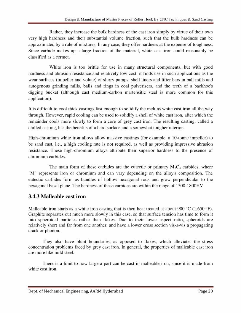
Fig: 5.6 pattern layout

Design & Manufacture of Master Pieces of Roller Hook By CNC Techniques & Sand Casting
Dept. of Mechanical Engineering, AARM Hyderabad Page 29
CHAPTER-6
INTRODUCTION TO MANUFACTURING
6.1 Introduction to CAM
Computer-integrated manufacturing (CIM) is the manufacturing approach of using computers to
control the entire production process. This integration allows individual processes to exchange
information with each other and initiate actions. Through the integration of computers,
manufacturing can be faster and less error-prone, although the main advantage is the ability to
create automated manufacturing processes. Typically CIM relies on closed-loop control
processes, based on real-time input from sensors. It is also known as flexible design and
manufacturing.
The term "computer-integrated manufacturing" is both a method of manufacturing and the name
of a computer-automated system in which individual engineering, production, marketing, and
support functions of a manufacturing enterprise are organized. In a CIM system functional areas
such as design, analysis, planning, purchasing, cost accounting, inventory control, and
distribution are linked through the computer with factory floor functions such as materials
handling and management, providing direct control and monitoring of all the operations.
As a method of manufacturing, three components distinguish CIM from other manufacturing
methodologies:
Means for data storage, retrieval, manipulation and presentation;
Mechanisms for sensing state and modifying processes;
Algorithms for uniting the data processing component with the sensor/modification
component.
CIM is an example of the implementation of information and communication
technologies (ICTs) in manufacturing.
CIM implies that there are at least two computers exchanging information, e.g. the controller of
an arm robot and a micro-controller of a CNC machine.
Some factors involved when considering a CIM implementation are the production volume, the
experience of the company or personnel to make the integration, the level of the integration into
the product itself and the integration of the production processes. CIM is most useful where a
high level of ICT is used in the company or facility, such as CAD/CAM systems, the availability
of process planning and its data.

Design & Manufacture of Master Pieces of Roller Hook By CNC Techniques & Sand Casting
Dept. of Mechanical Engineering, AARM Hyderabad Page 30
6.2 Introduction to CNC Machining
Numerical control (NC) is the automation of machine tools that are operated by precisely
programmed commands encoded on a storage medium, as opposed to controlled manually via
hand wheels or levers, or mechanically automated via cams alone. Most NC today is computer
numerical control (CNC), in which computers play an integral part of the control.
In modern CNC systems, end-to-end component design is highly automated
using computer-aided design (CAD) and computer-aided manufacturing (CAM) programs. The
programs produce a computer file that is interpreted to extract the commands needed to operate a
particular machine via a post processor, and then loaded into the CNC machines for production.
Since any particular component might require the use of a number of different tools drills, saws,
etc. Modern machines often combine multiple tools into a single "cell". In other installations, a
number of different machines are used with an external controller and human or robotic
operators that move the component from machine to machine. In either case, the series of steps
needed to produce any part is highly automated and produces a part that closely matches the
original CAD design.
CNC like systems are now used for any process that can be described as a series of
movements and operations. These include laser cutting, welding, friction stir welding, ultrasonic
welding, flame and plasma cutting, bending, spinning, hole-punching, pinning, gluing, fabric
cutting, sewing, tape and fiber placement, routing, picking and placing (PnP), and sawing.

Design & Manufacture of Master Pieces of Roller Hook By CNC Techniques & Sand Casting
Dept. of Mechanical Engineering, AARM Hyderabad Page 31
6.3 Some of the CNC Machines
Mills:
CNC mills use computer controls to cut different materials. They are able to translate
programs consisting of specific number and letters to move the spindle to various locations and
depths.
Many use G-code, which is a standardized programming language that many CNC
machines understand, while others use proprietary languages created by their manufacturers.
These proprietary languages while often simpler than G-code are not transferable to other
machines.
Lathes:
Lathes are machines that cut spinning pieces of metal. CNC lathes are able to make fast,
precision cuts using index able tools and drills with complicated programs for parts that normally
cannot be cut on manual lathes.
These machines often include 12 tool holders and coolant pumps to cut down on tool
wear. CNC lathes have similar control specifications to CNC mills and can often read G-code as
well as the manufacturer's proprietary programming language.
Plasma cutters:
Plasma cutting involves cutting a material using a plasma torch. It is commonly used to
cut steel and other metals, but can be used on a variety of materials. In this process, gas (such
as compressed air) is blown at high speed out of a nozzle; at the same time an electrical arc is
formed through that gas from the nozzle to the surface being cut, turning some of that gas
to plasma.
The plasma is sufficiently hot to melt the material being cut and moves sufficiently fast to
blow molten metal away from the cut.

Design & Manufacture of Master Pieces of Roller Hook By CNC Techniques & Sand Casting
Dept. of Mechanical Engineering, AARM Hyderabad Page 32
6.4 Electric Discharge Machining
Electric discharge machining (EDM), sometimes colloquially also referred to as spark
machining, spark eroding, burning, die sinking, or wire erosion, is a manufacturing process in
which a desired shape is obtained using electrical discharges (sparks).
Material is removed from the work piece by a series of rapidly
recurring current discharges between two electrodes, separated by a dielectric fluid and subject to
an electric voltage. One of the electrodes is called the tool-electrode, or simply the ‘tool’ or ‘electrode’, while the other is called the work piece-electrode, or ‘work piece’.
When the distance between the two electrodes is reduced, the intensity of the electric
field in the space between the electrodes becomes greater than the strength of the dielectric (at
least in some point(s)), which breaks, allowing current to flow between the two electrodes. This
phenomenon is the same as the breakdown of a capacitor. As a result, material is removed from
both the electrodes.
Wire EDM
Also known as wire cutting EDM, wire burning EDM, or travelling wire EDM, this
process uses spark erosion to machine or remove material with a travelling wire electrode from
any electrically conductive material. The wire electrode usually consists of brass or zinc-coated
brass material.
This process is used to cut plates and to make punches, tools, and dies from any
conductive material, including hard metals that are too difficult to machine with other methods,
such as; metal allows, graphite, carbide and diamond.
Water jet cutters
A water jet cutter, also known as a water jet, is a tool capable of slicing into metal or
other materials (such as granite) by using a jet of water at high velocity and pressure, or a
mixture of water and an abrasive substance, such as sand. It is often used during fabrication or
manufacture of parts for machinery and other devices.
Water jet is the preferred method when the materials being cut are sensitive to the high
temperatures generated by other methods. It has found applications in a diverse number of
industries from mining to aerospace where it is used for operations such as cutting, shaping,
carving, and reaming.

Design & Manufacture of Master Pieces of Roller Hook By CNC Techniques & Sand Casting
Dept. of Mechanical Engineering, AARM Hyderabad Page 33
6.5 CNC Machine Programming
The way an operator tells the machine what exactly to do is through specialized
programming. The program is written with a bunch of sentence like commands.
Every single command is composed of particular CNC words which have both a letter
and number element. The letter describes the “kind” and the number describes the “value.” These instructions are literally step-by-step guidelines on what the machine should do at any given
point in the machining process.
Someone called a CNC programmer must first visualize the entire process as it would
happen during implementation. Then they would need to insert those steps into the program via
the different available commands/words.

Design & Manufacture of Master Pieces of Roller Hook By CNC Techniques & Sand Casting
Dept. of Mechanical Engineering, AARM Hyderabad Page 34
CHAPTER-7
INTRODUCTION TO PROGRAM
7.1 G-codes
G-code is the common name for the most widely used numerical control (NC)
programming language, which has many implementations. Used mainly in automation, it is part
of computer-aided engineering. G-code is sometimes called G programming language.
Rapid move (transport the tool through space to the place where it is needed for cutting;
do this as quickly as possible).
Controlled feed move in a straight line or arc.
Series of controlled feed moves that would result in a hole being bored, a workpiece cut
(routed) to a specific dimension, or a profile (contour) shape added to the edge of a
workpiece.
Set tool information such as offset.
Switch coordinate systems.
Here are the most common G-codes with their function called out.
G00 Rapid positioning
G01 Linear interpolation
G02 Circular/helical interpolation (clockwise)
G03 Circular/helical interpolation (counter clockwise)
G04 Dwell
G10 Coordinate system origin setting
G17 XY plane selection
G18 XZ plane selection
G19 YZ plane selection
G20 Inch system selection
G21 Millimetre system selection
G40 Cancel cutter diameter compensation
G41 Start cutter diameter comp. left
G42 Start cutter diameter comp. right
G43 Tool length offset (plus)
G49 Cancel tool length offset
G53 Motion in machine coordinate system
G54 Use preset work coordinate system 1
G55 Use preset work coordinate system 2

Design & Manufacture of Master Pieces of Roller Hook By CNC Techniques & Sand Casting
Dept. of Mechanical Engineering, AARM Hyderabad Page 35
G56 Use preset work coordinate system 3
G57 Use preset work coordinate system 4
G58 Use preset work coordinate system 5
G59 Use preset work coordinate system 6
G59.1 Use preset work coordinate system 7
G59.2 Use preset work coordinate system 8
G59.3 Use preset work coordinate system 9
G80 Cancel motion mode (includes canned)
G81 Drilling canned cycle
G82 Drilling with dwell canned cycle
G83 Chip-breaking drilling canned cycle
G84 Right hand tapping canned cycle
G85 Boring, no dwell, feed out canned cycle
G86 Boring, spindle stop, rapid out canned
G87 Back boring canned cycle
G88 Boring, spindle stop, manual out canned
G89 Boring, dwell, feed out canned cycle
G90 Absolute distance mode
G91 Incremental distance mode
G92 Offset coordinate systems
G92.2 Cancel offset coordinate systems
G93 Inverse time feed mode
G94 Feed per minute mode
G98 Initial level return in canned cycles

Design & Manufacture of Master Pieces of Roller Hook By CNC Techniques & Sand Casting
Dept. of Mechanical Engineering, AARM Hyderabad Page 36
7.2 M-codes
Default M codes used on most machines types. User customizable M codes will change
based on application and user definition.
Machine code
MATLAB programming language
Military GPS signal
Half of the G & M-Code programming language used in the CNC Machining Industry.
M02 End of Program
M03 Spindle On Clockwise, Laser, Flame, Power ON
M04 Spindle On Counter Clockwise
M05 Spindle Stop, Laser, Flame, Power OFF
M06 Tool Change
M08 Coolant On
M09 Coolant Off
M10 Reserved for tool height offset
M13 Spindle On, Coolant On
M30 End of Program when macros are used
M91 Readout Display Incremental
M92 Readout Display Absolute
M97 Go to or jump to line number
M98 Jump to macro or subroutine
M99 Return from macro or subroutine
M100 Machine Zero Reset
M199 Mid program start

Design & Manufacture of Master Pieces of Roller Hook By CNC Techniques & Sand Casting
Dept. of Mechanical Engineering, AARM Hyderabad Page 37
7.3 Computer Numerical Control Machine
Most CNC milling machines (also called machining canters) are computer controlled
vertical mills with the ability to move the spindle vertically along the Z-axis. This extra degree of
freedom permits their use in die sinking, engraving applications, and 2.5D surfaces such
as relief sculptures. When combined with the use of conical tools or a ball nose cutter, it also
significantly improves milling precision without impacting speed, providing a cost-efficient
alternative to most flat-surface hand-engraving work.
Fig: 7.1 five-axis machining center with rotating table and computer interface
CNC machines can exist in virtually any of the forms of manual machinery, like
horizontal mills. The most advanced CNC milling-machines, the multi-axis machine, add two
more axes in addition to the three normal axes (XYZ). Horizontal milling machines also have a
C or Q axis, allowing the horizontally mounted workpiece to be rotated, essentially allowing
asymmetric and eccentric turning. The fifth axis (B axis) controls the tilt of the tool itself. When
all of these axes are used in conjunction with each other, extremely complicated geometries,
even organic geometries such as a human head can be made with relative ease with these
machines. But the skill to program such geometries is beyond that of most operators. Therefore,
5-axis milling machines are practically always programmed with CAM.
The Operating system of such machines is a closed loop system and functions on
feedback. These machines have developed from the basic NC (NUMERIC CONTROL)
machines. A computerized form of NC machines is known as CNC machines. A set of
instructions (called a program) is used to guide the machine for desired operations.
CNC machine is operated by a single operator called a programmer. This machine is
capable of performing various operations automatically and economically. While reading this
article, along with collecting other information about milling machines, it is crucial for one to
understand the computerized form of such machines

Design & Manufacture of Master Pieces of Roller Hook By CNC Techniques & Sand Casting
Dept. of Mechanical Engineering, AARM Hyderabad Page 38
7.4 Tooling
The accessories and cutting tools used on machine tools (including milling machines) are
referred to in aggregate by the mass noun "tooling". There is a high degree of standardization of
the tooling used with CNC milling machines, and a lesser degree with manual milling machines.
To ease up the organization of the tooling in CNC production many companies use a tool
management solution.
Milling cutters for specific applications are held in various tooling configurations.
Fig: 7.2 high speed steel with cobalt end mills used for cutting operations in a milling
machine
CNC milling machines nearly always use SK (or ISO), CAT, BT or HSK tooling. SK
tooling is the most common in Europe, while CAT tooling, sometimes called V-Flange Tooling,
is the oldest and probably most common type in the USA. CAT tooling was invented
by Caterpillar Inc. of Peoria, Illinois, in order to standardize the tooling used on their machinery.
CAT tooling comes in a range of sizes designated as CAT-30, CAT-40, CAT-50, etc. The
number refers to the Association for Manufacturing Technology (formerly the National Machine
Tool Builders Association (NMTB)) Taper size of the tool.
Design & Manufacture of Master Pieces of Roller Hook By CNC Techniques & Sand Casting
Dept. of Mechanical Engineering, AARM Hyderabad Page 39
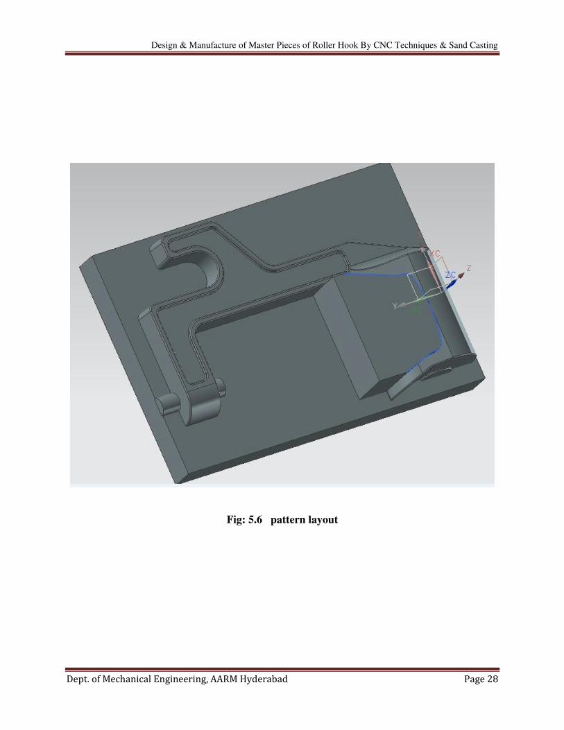
Fig: 7.3 a CAT-40 tool holder Fig: 7.4 a boring head on a Morse taper shank
SK and HSK tooling, sometimes called "Hollow Shank Tooling", is much more common
in Europe where it was invented than it is in the United States. It is claimed that HSK tooling is
even better than BT Tooling at high speeds. The holding mechanism for HSK tooling is placed
within the (hollow) body of the tool and, as spindle speed increases, it expands, gripping the tool
more tightly with increasing spindle speed. There is no pull stud with this type of tooling.

Design & Manufacture of Master Pieces of Roller Hook By CNC Techniques & Sand Casting
Dept. of Mechanical Engineering, AARM Hyderabad Page 40
CHAPTER-8
INTRODUCTION TO DELCAM
Power mill is a 3D CAM (Computer-aided manufacturing) solution that runs
on Microsoft Windows for the programming of tool paths for 2 to 5 axis CNC (Computer
Numerical Control) Milling machines developed by Delcam Plc. The software is used in a range
of different engineering industries to determine optimal tool paths to reduce time and
manufacturing costs as well as reduce tool loads and produce smooth surface finishes.
The code of Power mill originates from the software DUCT which was developed in 1973
by Donald Welbourne and Ed Lambourne along with the help of Delta Metal Group, whose
funding aided the transferral of the system into industry. The advancement of mini computers
from 1982 meant that it became economically viable to design complex 3D shapes using a
computer
8.1 Raw Material Specifications
Aluminium (or aluminium) is a chemical element in the boron group with
symbol Al and atomic number 13. It is a silvery white, soft, ductile metal. Aluminium is the third
most abundant element(after oxygen and silicon), and the most abundant metal, in
the Earth's crust. It makes up about 8% by weight of the Earth's solid surface.
Aluminum is remarkable for the metal's low density and for its ability to
resist corrosion due to the phenomenon of passivation. Structural components made from
aluminum and its alloys are vital to the aerospace industry and are important in other areas
of transportation and structural materials. The most useful compounds of aluminum, at least on a
weight basis, are the oxides and sulfates.
Physical
Aluminium is a relatively soft, durable, lightweight, ductile and malleable metal with
appearance ranging from silvery to dull gray, depending on the surface roughness. It is
nonmagnetic and does not easily ignite. The yield strength of pure aluminium is 7–11 MPa,
while aluminium alloys have yield strengths ranging from 200 MPa to 600 MPa. Aluminium has
about one-third the density and stiffness of steel. It is easily machined, cast, drawn and extruded.
Chemical
Corrosion resistance can be excellent due to a thin surface layer of aluminium oxide that
forms when the metal is exposed to air, effectively preventing further oxidation. The strongest
aluminium alloys are less corrosion resistant due to galvanic reactions with alloyed copper. This
corrosion resistance is also often greatly reduced by aqueous salts, particularly in the presence of
dissimilar metals.
Due to above advantages we used rectangular Aluminium block with the dimensions
164x60x37 as raw material for making bearing housing patterns.

Design & Manufacture of Master Pieces of Roller Hook By CNC Techniques & Sand Casting
Dept. of Mechanical Engineering, AARM Hyderabad Page 41
Fig: 8.1 raw material factors
8.2 Pattern Manufacturing Process:
Fig: 8.2 DELCAM starting Fig: 8.3 File importing

Design & Manufacture of Master Pieces of Roller Hook By CNC Techniques & Sand Casting
Dept. of Mechanical Engineering, AARM Hyderabad Page 42
Fig: 8.4 work plane and raw material block creation
Fig: 8.5 tool path generation

Design & Manufacture of Master Pieces of Roller Hook By CNC Techniques & Sand Casting
Dept. of Mechanical Engineering, AARM Hyderabad Page 43
Fig: 8.6 creating tool path for finishing
Fig: 8.7 surfacing tool path

Design & Manufacture of Master Pieces of Roller Hook By CNC Techniques & Sand Casting
Dept. of Mechanical Engineering, AARM Hyderabad Page 44
Fig: 8.8 tool path simulations

Design & Manufacture of Master Pieces of Roller Hook By CNC Techniques & Sand Casting
Dept. of Mechanical Engineering, AARM Hyderabad Page 45
8.3 Generation of CNC Program for Tool Paths
ROUGHING TOOL PATH:
%
: 0001
G91 G28 X0 Y0 Z0
G40 G17 G80 G49
G0 G90 Z45.
T1 M6
G54 G90 T0
( Toolpath Name: 1 )
(Output: )
(Units: MM )
(Tool Coordinates: Tip )
(Tool Number: 1 )
(Tool Id: 1 )
(Coolant: Standard )
(Gauge Length: 40.000 )
(Block: )
(MIN X: -82.000 )
(MIN Y: -30.000 )
(MIN Z: -38.000 )
(MAX X: 82.000 )
(MAX Y: 30.000 )
(MAX Z: 0.000 )
(COORDINATE SYSTEM: Active Workplane )
(Datum - Tool Tip: )

Design & Manufacture of Master Pieces of Roller Hook By CNC Techniques & Sand Casting
Dept. of Mechanical Engineering, AARM Hyderabad Page 46
(X: 0.000)
(Y: 0.000)
(Z: 45.000)
(Number of Flutes: 1)
(Tool: End Mill)
(DIAMETER: 8.000)
(Safety)
(Tool Cutting Moves: Safe No Gouges)
(Tool Leads: Safe No Gouges)
(Tool Links: Safe No Gouges)
(Holder Cutting Moves: Collisions Not Checked)
(Holder Leads: Collisions Not Checked)
(Holder Links: Collisions Not Checked)
( Toolpath: Offset Area Clearance )
(STEPOVER: 5.000 )
(TOLERANCE:0.100 )
(THICKNESS:0.250 )
( Toolpath Stats: )
(LENGTH: 151773.039)
(TIME: 2/29/35)
(LIFTS: 112)
X-43.664 Y-5.307 S1500 M3
G43 Z40. H1 M8
G1 Z.5 F500
X-43.742 Y-5.711 Z.464
X-44.169 Y-7.485 Z.304
X-44.756 Y-9.213 Z.145

Design & Manufacture of Master Pieces of Roller Hook By CNC Techniques & Sand Casting
Dept. of Mechanical Engineering, AARM Hyderabad Page 47
X-45.247 Y-10.47 Z.027
X-45.519 Y-11.13 Z-.036
X-45.815 Y-11.78 Z-.098
X-41.422 Z-.482
X-37.029 F1000
X-37.435 Y-10.503
X-37.707 Y-9.569
G1 X-74.261 Y19.061
X-74.141 Y18.812
G0 Z45.
M9
G91 G28 Z0
G49 H0
G28 X0 Y0
M30
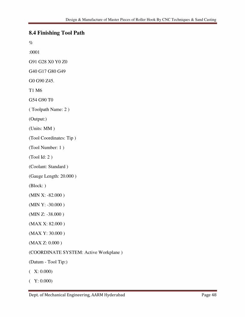
Design & Manufacture of Master Pieces of Roller Hook By CNC Techniques & Sand Casting
Dept. of Mechanical Engineering, AARM Hyderabad Page 48
8.4 Finishing Tool Path
%
:0001
G91 G28 X0 Y0 Z0
G40 G17 G80 G49
G0 G90 Z45.
T1 M6
G54 G90 T0
( Toolpath Name: 2 )
(Output:)
(Units: MM )
(Tool Coordinates: Tip )
(Tool Number: 1 )
(Tool Id: 2 )
(Coolant: Standard )
(Gauge Length: 20.000 )
(Block: )
(MIN X: -82.000 )
(MIN Y: -30.000 )
(MIN Z: -38.000 )
(MAX X: 82.000 )
(MAX Y: 30.000 )
(MAX Z: 0.000 )
(COORDINATE SYSTEM: Active Workplane )
(Datum - Tool Tip:)
( X: 0.000)
( Y: 0.000)

Design & Manufacture of Master Pieces of Roller Hook By CNC Techniques & Sand Casting
Dept. of Mechanical Engineering, AARM Hyderabad Page 49
( Z: 45.000)
(Number of Flutes: 1 )
(Tool: Ball Nosed )
(DIAMETER: 4.000 )
(Safety: )
(Tool Cutting Moves: Safe No Gouges )
(Tool Leads: Safe No Gouges )
(Tool Links: Safe No Gouges )
(Holder Cutting Moves: Collisions Not Checked )
(Holder Leads: Collisions Not Checked)
(Holder Links: Collisions Not Checked )
( Toolpath: Optimised Constant Z )
( STEPOVER: 0.250 )
( TOLERANCE:0.100 )
( THICKNESS:0.000 )
( Toolpath Stats: )
( LENGTH: 106400.392 )
( TIME: 1/31/39 )
( LIFTS: 221 )
X-70.139 Y.211 S1500 M3
G43 Z40. H1 M8
G1 Z.5 F500
X-69.847 Y.233 Z.474
X-69.741 Y.042 Z.455
X-69.744 Y-.125 Z.441
X-73.26 Y20.826
X-73.336 Y20.854

Design & Manufacture of Master Pieces of Roller Hook By CNC Techniques & Sand Casting
Dept. of Mechanical Engineering, AARM Hyderabad Page 50
Y21.27
X-73.26 Y21.345
X-71.345 Y21.344
G0 Z45.
M9
G91 G28 Z0
G49 H0
G28 X0 Y0
M30

Design & Manufacture of Master Pieces of Roller Hook By CNC Techniques & Sand Casting
Dept. of Mechanical Engineering, AARM Hyderabad Page 51
8.5 Results
Fig: 8.9 master print machining
Fig: 8.10 assembly of hook with masters

Design & Manufacture of Master Pieces of Roller Hook By CNC Techniques & Sand Casting
Dept. of Mechanical Engineering, AARM Hyderabad Page 52
Fig: 8.11 core box assembly components

Design & Manufacture of Master Pieces of Roller Hook By CNC Techniques & Sand Casting
Dept. of Mechanical Engineering, AARM Hyderabad Page 53
CONCLUSION
The material HE30 used for making pattern plays an important role for high production
rate.
Designing techniques are presented for sand casting patterns.
CNC programming also introduced to get high accuracy in pattern making.

Design & Manufacture of Master Pieces of Roller Hook By CNC Techniques & Sand Casting
Dept. of Mechanical Engineering, AARM Hyderabad Page 54
REFERENCES
1. Degarmo, E. Paul; Black, J T.; Kohser, Ronald A. (2003), Materials and Processes in
Manufacturing (9th ed.), Wiley, p. 277, ISBN 0-471-65653-4
2. Ravi, B. (2005), Metal Casting: Computer-Aided Design and Analysis (1st ed.),
PHI, ISBN 81-203-2726-8
3. T F Waters (11 September 2002). Fundamentals of Manufacturing For Engineers CRC
Press Pp 17– ISBN 978-0-203-50018-7
4. V Mehta, JS Cooper - Journal of Power Sources, 2003 - Elsevier
5. Sidney Pollard (1993). A History of Labour in Sheffield Gregg Revivals. pp. 284–
285. ISBN 978-0-7512-0215-1
6. James T. Frane (1994) Craftsman's Illustrated Dictionary of Construction Terms.
Craftsman Book Company pp. 126– ISBN 978-1-57218-008-6
7. Campbell, John (1993). Castings Butterworth-Heinemann p. 49 ISBN 0-7506-1696-2
8. "Sand Casting - The Designers & Buyers Guide" www.manufacturingnetwork.com.
Retrieved 2016-03-29
9. Metal Casting Techniques - Vacuum ("V") Process Molding, retrieved 2009-11-09
10. Dean, Al. "PowerShape Pro 2013". Develop3D. Retrieved 2012-10-25
11. Siemens Closes Acquisition of UGS; Introduces Business as UGS PLM Software"
12. Gopi (2010-01-01). Basic Civil Engineering. Pearson Education
India. ISBN 9788131729885
13. Kreith, Frank (1998). The CRC handbook of mechanical engineering. CRC Press. p. 15-
1. ISBN 978-0-8493-9418-8
14. Dokken, Tor. "The History of CAD". The SAGA-project. Retrieved 17 May 2012
15. Hosking, Dian Marie; Anderson, Neil (1992), Organizational change and innovation,
Taylor & Francis, p. 240, ISBN 978-0-415-06314-2
16. Chapter 82 – Metal Processing and Metal Working Industry". Encyclopaedia of
Occupational Health and Safety, 4th Edition. Retrieved 26 October 2011
17. CAM Toolpath Strategies. CNC Cookbook. Retrieved on 2012-01-17
18. Delcam Rated World's Leading CAM Software Specialist for 12th Year". tct. 2012-08-
02. Retrieved 2012-11-15

Design & Manufacture of Master Pieces of Roller Hook By CNC Techniques & Sand Casting
Dept. of Mechanical Engineering, AARM Hyderabad Page 55
19. Welbourn, Donald. "The Development of Computer Aided Design and Manufacture -
CADCAM". Cambridge University Engineering Department. Retrieved 15 April 2014
20. Autodesk Completes Acquisition of Delcam". Autodesk. Retrieved 15 April 2014
21. Board Committee". Delcam website. Archived from the original on 3 April 2015.
Retrieved 2015-03-08
22. Delcam's New PowerSHAPE CAD Enhances Direct Modelling and Reverse
Engineering". CIMdata. Retrieved 2012-10-29
23. Delcam to Launch New PowerINSPECT with Free Birmingham Seminar". tct magazine.
2012-07-06. Retrieved 2012-11-05
24. Campbell, F.C. (2008). Elements of Metallurgy and Engineering Alloys. Materials Park,
Ohio: ASM International. p. 453. ISBN 978-0-87170-867-0
25. Wagner, Donald B. (1993). Iron and Steel in Ancient China. BRILL. pp. 335–
340. ISBN 978-90-04-09632-5
26. CAM Toolpath Strategies. CNC Cookbook. Retrieved on 2012-01-17.
27. Narayan, K. Lalit (2008). Computer Aided Design and Manufacturing. New Delhi:
Prentice Hall of India. p. 3. ISBN 812033342X
28. Duggal, Vijay (2000). Cadd Primer: A General Guide to Computer Aided Design and
Drafting-Cadd, CAD. Mailmax Pub. ISBN 978-0962916595
29. About CNC Machining". www.thomasnet.com. Retrieved 2016-06-04
30. Mike Lynch, "Key CNC Concept #1—The Fundamentals Of CNC", Modern Machine
Shop, 4 January 1997. Accessed 11 February 2015
31. Zelinski, Peter (2014-03-14), "New users are adopting simulation software", Modern
Machine Shop
32. Reintjes, J. Francis (1991), Numerical Control: Making a New Technology, Oxford
University Press, ISBN 978-0-19-506772-9
33. Fahlman, Bradley D. (2011-03-18). Materials chemistry (2.ed.). Dordrecht [u.a.]
Springer. ISBN 978-94-007-0692-7
34. non ferrous metals . Engineers Handbook. Retrieved 25 October 2011
35. Gupta, R. C. (2010). Theory and laboratory experiments in ferrous metallurgy. New
Delhi: PHI Learning Private Ltd. p. 6. ISBN 978-81-203-3924-8