Underwater cleaning technology Underwater cleaning technology.

UNION COLLEGE
Design and Implementation of Underwater Data
Collection and Communication System
Sreynoch Chin
ECE 499: Senior Capstone Project 3
Advisor: Professor James Hedrick
03/13/2012

2 Sreynoch Chin Design and Implementation of Underwater Data Collection and Communication
Report Summary
Located 8 miles northeast of Union College is Ballston Lake. Ballston Lake has some
unique characteristics that not many lakes have. For instance, Ballston Lake has not been having
intermixing between water layers for thousands of years and its south basin is permanently
stratified. As a result, there is no oxygen in lower water column. These unique characteristics
inspired the Union College Geology department to do a research study of the lake’s water
characteristics for 10 years. The Geology department would like to collect data from the lake
such as temperature, pH, salinity, and dissolved oxygen. However, the problem is there is no
commercially available system that would do data collection automatically. Currently, the
Geology department is doing data collection manually, which is very tedious and time
consuming. As a solution to this problem, an automatic remote water monitoring system is
designed and implemented to assist the Geology department in its data collection process.
Recently, a wireless data receiving and transmission system from Ballston Lake’s
computer to Union College computer was designed and implemented by a 2011 Electrical
Engineering student, Aung Soe. He used RF signals to transmit collected data from the lake
shore to Union College and vice versa. However, data collection from a sensor package under
the water and data transmission from under the water to the lake’s computer does not exist.
Therefore, my project designed and implemented a prototype for an automatic system that would
collect data from under the water and transmit the data to the lake shore.
The automatic underwater system will be used as part of the long-term water monitoring
system for Ballston Lake. This system will provide users ease and convenience of data collection
from under the water as well as reduction in time for collecting the data. This system will assist
the Union College Geology Department in its research study for 10 years.
The system design contained both hardware and software components. The main
hardware components consist of a DC motor, a motor controller, and a control computer
(c8051F340). The motor controller will control the sensor package to go to upper water layers
and to lower water layers and collect data at each layer in order to understand the lake’s
characteristics at various layers. The software components will enable users to control the
hardware components from the lake shore.

3 Sreynoch Chin Design and Implementation of Underwater Data Collection and Communication
Table of Contents
1. Introduction ............................................................................................................................. 5
1.1 Problem Statement ................................................................................................................ 5
2. Background ................................................................................................................................. 7
2.1. Data Communication............................................................................................................ 7
2.2. Related Research Work ........................................................................................................ 8
2.3. Motivation ............................................................................................................................ 8
3. System Specifications ................................................................................................................. 9
3.2 Goals.................................................................................................................................... 13
4. Design Alternatives ................................................................................................................... 13
4.1. Hardware Alternatives........................................................................................................ 13
4.1.1. Data link from the bottom lake to lake shore .............................................................. 13
4.1.2. Control Computer ........................................................................................................ 14
4.1.3. Motor ........................................................................................................................... 17
4.2. Software Alternatives ......................................................................................................... 18
5. Final Design and Prototype Implementation ............................................................................ 19
5.1 Hardware Design ................................................................................................................. 19
5.1.1 Data Collection ............................................................................................................. 20
5.1.2 Data Storage ................................................................................................................. 22
5.1.3 Data Transmission ........................................................................................................ 22
5.2 Software Design .................................................................................................................. 22
5.2.2 Packet Format ................................................................................................................... 23
5.2.2 Fundamental Behaviors of a Protocol .............................................................................. 27
6. Testing & Results ...................................................................................................................... 29
6.1. Hardware Testing & Results .............................................................................................. 29
6.1.1 Testing with weather balloon ....................................................................................... 29
6.1.2 Testing the motor .......................................................................................................... 30
6.2. Testing Software ............................................................................................................. 31
7. Conclusion and Future Work .................................................................................................... 32
References ..................................................................................................................................... 33
Appendix A ................................................................................................................................... 34

4 Sreynoch Chin Design and Implementation of Underwater Data Collection and Communication
Table of Figures
FIGURE 1: A BLOCK DIAGRAM OF A REMOTE WATER MONITORING SYSTEM .................................................................. 6
FIGURE 2: A BLOCK DIAGRAM OF THE UNDERWATER DATA COLLECTION SUBSYSTEM ..................................................... 9
FIGURE 3: SAMPLE WATER PROPERTY DATA MEASUREMENTS .................................................................................. 11
FIGURE 4: C8051F340-TB CONNECTED TO AB5 EXPANSION BOARD WITH SD CARD [6] ........................................... 14
FIGURE 5: A PIN DIAGRAM OF SILICON LAB’S C8051F340 MICROCONTROLLER DEVELOPMENT BOARD [4] .................... 15
FIGURE 6: COMPARISON OF PEAK MCU EXECUTION SPEED .................................................................................... 16
FIGURE 7: THE SLIP RING FROM THE SIDE ............................................................................................................. 17
FIGURE 8: THE SLIP RING FROM THE TOP ............................................................................................................. 18
FIGURE 9: MOTOR REEL AND HYDROLAB SENSOR ............................................................................................... 21
FIGURE 10: MOTOR CONTROLLER ....................................................................................................................... 21
FIGURE 11: (A) CONTROL PACKET FORMAT AND (B) DATA PACKET FORMAT ............................................................... 24
FIGURE 12: A TIME SEQUENCE DIAGRAM OF A PROTOCOL DESIGN............................................................................ 26
FIGURE 13: A FLOWCHART DIAGRAM FOR A SENDER PROGRAM AND A RECEIVER PROGRAM ......................................... 27
FIGURE 14: LEAKED WEATHER BALLOON .............................................................................................................. 30
FIGURE 15: MOTOR CONTROLLER WITH A HEAT SINK ATTACHED .............................................................................. 31
FIGURE 16: A SNAPSHOT OF SUCCESSFUL DATA TRANSFER FROM LAKE BOTTOM TO LAKE SHORE ................................... 32

5 Sreynoch Chin Design and Implementation of Underwater Data Collection and Communication
1. Introduction
Ballston Lake located 8 miles northeast of Union College comprises unique and
interesting characteristics which offer excellent research opportunities to students and faculties at
Union College Geology Department. The lake is approximately 3.5 miles in length and 750 feet
in width [1]. The south basin of the lake is known to be meromictic. Which means that his part of
the lake is permanently stratified, and there has been no intermixing between water layers for
thousands of years. The water depth at this part of the lake is about 130 feet. The deep water in
the lake has some unique characteristics. It contains no oxygen at the lower columns but has high
levels of carbon dioxide and other gases. The Geology Department at Union College has been
very interested in studying the water columns at Ballston Lake for a period of ten years. The
department has purchased a multi-parameter water quality sensor package together with a data
logging system to collect water property data such as temperature, pH, conductivity, salinity,
redox, dissolved oxygen at various depths.
1.1 Problem Statement
Refer to figure 1 for a block diagram of the entire system. The automatic RF data
communication system, which transmits data from Ballston Lake shore to Union College and
vice versa, was designed and implemented by a 2011 Union College student. However, no
automatic underwater data collection and communication system is implemented in the current
research study. Presently, one person on the lake site takes periodic measurements manually
from the sensor package through the data-logging unit. The current manual water quality
monitoring entails tedious process and is time consuming. For these reasons, it is desirable to
have a data collection and communication system with characteristics of autonomous, reliable
and flexible. Figure 1 illustrates design of a remote water system.

6 Sreynoch Chin Design and Implementation of Underwater Data Collection and Communication
Figure 1: A block diagram of a remote water monitoring system
This system will be used for long-term water monitoring of Ballston Lake. The system will allow
users to collect and transmit the water property data automatically without having most of the
tedious human involvement. In addition, the system will not only offer a large amount of data
storage space but also provide a convenient technique to manage and analyze data to help answer
numerous questions concerning this fascinating lake.

7 Sreynoch Chin Design and Implementation of Underwater Data Collection and Communication
2. Background
2.1. Data Communication
Any process that passes messages from a sender to one or more receivers can be
considered as data communication. The message can be in electrical signal form or in sound.
Data communication is only interested in the transfer of data, the method of transfer and the
preservation of the data during the transfer process.
The earliest roots of data communication dated back to the 19th
century when the
invention of telegraph system by Samuel Morse occurred. The first commercial electrical
telegraph in the United States was invented by Samuel Morse in 1837 [2]. During the same year,
William Cooke and Sir Charles Wheatstone built the telegraph independently in the United
Kingdom [2]. These early establishments of data communication systems relied on wired
connections to communicate between two stations. As wired data communication expanded, a
separate form of data exchange that required no wires experienced a concurrent development. In
1873, James Maxwell mathematically predicted the existence of electromagnetic waves. More
than a decade later, in 1886, Heinrich Hertz demonstrated that rapid variations of electric current
could be projected into space in the form of radio waves similar to those of light and heat. His
demonstration proved the existence of the electromagnetic waves. Oliver Lodge, a British
physicist and writer, demonstrated wireless communication over a distance of 150 yards in 1894.
Shortly thereafter, Guglielmo Marconi, an Italian inventor, established the first long distance
wireless transmission by sending telegraph signals over two kilometer from ship to shore in
1896[2]. The fundamental work of scientists of the nineteenth century paved the way with
invaluable theoretical and experimental discoveries related to both wired and wireless data
communication systems.
The advancement in the digital computer during the late 1950s even induced more
technological development in data communications. Data communication has become an
extremely important aspect of the modern world. It has been a subject of great interest for many
applications for many decades.

8 Sreynoch Chin Design and Implementation of Underwater Data Collection and Communication
Transmission media and the data communication protocols are the two key aspect of data
communication system. The transmission medium is the physical path over which data travels
from the source to the receiver. The transmission medium can be a twisted-pair of copper wires,
coaxial cable, optical fiber or wireless media such as radio waves. On the other hand, the
communication protocol is a set of rules and conventions essential for the source and the receiver
to communicate reliably and efficiently. Two devices wishing to communicate with each other
cannot just begin data transmission arbitrarily. The sender and the receiver must agree on a
common set of rules, protocols before they can communicate with each other.
2.2. Related Research Work
There are many different types of data transmission systems available in the market to
meet most remote water monitoring application needs. Global Water offers several types
including cellular data transmission systems, satellite data transmission systems, radio data
transmission systems and telephone modem data transmission sets for the remote water
monitoring system. In addition, Stevens remote telemetry systems offers effective wireless
communication technologies data include cellular, radio and satellite telemetry. Although data
telemetry systems from both of these two companies might provide viable solutions for this
project, they are pre-configured with limited capabilities and difficult to expend for future
integration of the system for this specific kind of research purpose. Moreover, these
commercially available systems still have relatively high price.
2.3. Motivation
The purpose of my project is to design and implement a reliable autonomous underwater
data collection and communication subsystem for a remote water monitoring system; refer to
figure 1 for the remote monitoring system. The system is intended to assist the Union College
Geology Department in its research study of the lake’s water characteristics. By implementing
this autonomous subsystem, users at the lake shore will be able to access to a more convenient
and time efficient data collection process than the current process which done manually.
This paper presents in detail the design and implementation of the underwater data
collection and communication subsystem for remote water monitoring. This design report begins

9 Sreynoch Chin Design and Implementation of Underwater Data Collection and Communication
with background information. Then, system specifications will also be discussed to address
essential basic system functionalities. Possible design alternatives for major components of the
designed will also be examined. Next, the final design and implementation as well as testing &
results will be explained and discussed.
3. System Specifications
In order for the autonomous underwater data collection subsystem work reliably, it is
required that the system functions properly and continuously for at least over a period of 10
years. To achieve this, requirements for the underwater subsystem are needed.
Figure 2: A block diagram of the underwater data collection subsystem

10 Sreynoch Chin Design and Implementation of Underwater Data Collection and Communication
Main components of this subsystem comprised of control computer, motor controller,
sensor package, and a 12V battery. Detailed descriptions of these components can be found in
Design Alternative Section. The followings are design requirements:
Operate continuously for 10 years
The system must operate continuously at least 10 years of period for a long-term research
purpose. According to Prof. Shaw from the Geology Department, the long-term research is
necessary to observe possible unusual occurrences as well as unique water characteristics within
the lake by analyzing the water property data. The durability and reliability of hardware
equipments (especially the motor and motor controller) and the functionality of software
components will greatly affect the overall performance of the system.
The Underwater Data Collection Subsystem must operate reliably at depth of 130
feet, and a distance of 130 feet from the lake shore.
The distance between two communicating stations is another important criterion for the
subsystem. Any serial data transmission must account for how far apart are two stations. The
estimated direct-distance between the bottom of Ballston Lake and the shore of Ballston Lake is
about 130 feet. The distance from the shore to the PC running Linux is 130 feet.
Collect data at every foot within the lake’s depth
Every day the sensor package has to collect water data from the bottom of the lake to
near the surface of the lake. This can be done by moving the sensor package from one
water layer to another water layer at an increment of 1 foot. The speed of moving from
one layer to another layer is 1 foot per 5 seconds. Once the sensor package is at its new
water level, the sensor has to collect a number of data until the varying values of the
collected temperatures are no longer greater than degree Celsius. Then final data is
collected and sent to the control computer.

11 Sreynoch Chin Design and Implementation of Underwater Data Collection and Communication
Provide data storage in control computer
Data transmitted by the sensor package need to be stored in the control computer before it
is sent to the shore. This is because although the amount of data from a single measurement of
water properties from the sensor package (as shown in Figure 3) is relatively small, we would
like to have store a certain amount of data in the control computer as a backup in case data
transmitted from the controller to the shore unexpectedly get corrupted. Additionally, since the
microcontroller will have to collect data from the sensor package and transmit the data to the
shore, the microcontroller have to have at least 2 UARTs.
Figure 3: Sample water property data measurements
Minimum of 9600 bits/sec for the transmission rate
According to Professor George Shaw from the Union College Geology Department, 3
measurements will be taken at every foot starting from the bottom of the lake. Since the lake is
130 feet deep, there will be total of 130 sets of measurements for every complete process of data
collection. This process will be repeated every day for 10 years of period. Each measurement
contains variable length of character which depends on the number of water property to be
measured. Given the amount of data that will be collected in the lake through the sensor package,
the system needs to have minimum of 9600 bps (bits per second) for the transmission rate in
order to establish effective communication between two sites in timely manner. We chose 9600
bits/sec because the amount of data is not too much to requirement a faster rate. Plus, a faster
data rate associates with a higher probably of error in data transmitted.

12 Sreynoch Chin Design and Implementation of Underwater Data Collection and Communication
Need error checking, reporting and retransmission
The system requires additional capabilities such as error checking, error reporting and
retransmission in order to achieve reliable data transmission. The error checking mechanism is
needed to allow the receiver (the shore’s computer) to detect when bit errors have occurred.
Error reporting serves as the receiver’s explicit feedback to notify the sender (the control
computer) whether or not a packet is received correctly. If the receiver receives a packet with
errors, the sender will retransmit by the same packet.
Water tight components
All electronic components such as motor, motor controller, control computer, and 12V
battery will be anchored at the bottom of the lake for the period of 10 years. Thus, it is crucial
that no water will leak into the package containing the electronic components and causes
damages. We do not want to unnecessarily replace any components that are under the water as
some components are quite expensive. Additionally, replacing certain parts of the underwater
components can be a time consuming and complicated task because of the interconnection of the
components and its location at the bottom of the lake.
Ability to remotely charge battery
The 12V battery will power both the control computer and motor controller while it is at
the bottom of the lake. It is desirable that users at the lake shore will not have to pull the battery
out of the water and replace it with a new one when the battery is low or dead. Replacing the
battery is complicated and not cost efficient. Therefore, it is necessary that the users have the
ability to command the battery remotely from the shore to recharge.
Prevent overheating
Every day, the motor will unwind the motor reel to lift the sensor package up 1 inch and
collect data at a certain water layer. The motor will continuously lifting the sensor package
and collect data with the 1 inch increment until the sensor reaches near the water surface.
Then, the motor command the motor reel to lower the sensor package all the way back to the
bottom of the lake. By winding and unwinding the motor reel continuously, motor controller
can overheat. Thus, it is important that overheating prevention is met in the design because
we do not want the overheating problem to cause damages to other electronic components.

13 Sreynoch Chin Design and Implementation of Underwater Data Collection and Communication
3.2 Goals
The objective of this project is to meet all of the above requirements in the project’s
design and implementation. Human involvement with the monitoring process is desired to be as
minimal as possible. The system is also intended to provide a secure data storage mechanism to
assist users manage large amount of data for future analysis. The ultimate goal is to relieve the
burden of collecting data manually and to provide a robust system that will be useful for the
Geology department in its research. Water is very important in human’s life; therefore,
understanding more about Ballston Lake will not benefit only the faculties and students at Union
College, but could be potentially useful to the society as a whole.
4. Design Alternatives
This section will take into consideration the design alternatives for both hardware and
software components of the underwater data collection and communication system.
4.1. Hardware Alternatives
4.1.1. Data link from the bottom lake to lake shore
Our first consideration of data link from the bottom of the lake to lake shore was a
wireless data transmission with an antenna right on the shore near the water. However, we had a
concern that a boat might hit the antenna and thus destroy and interrupt the connection and data
transmission between the control computer and the computer at the lake shore. As a result, we
considered fiber optics and copper wires instead. Fiber optics and copper wires both have to be
water proof and water tight. Fiber optics transmits information from one place to another by
sending pulses of light through an optical fiber. Its data rate capacity ranges from few hundreds
Mbits/s to ≈ 10Gbits/s. However, fiber optics is expensive and it needs to be specially installed.
Copper wires are cheap, but they are not long enough for connecting the controller to the shore.
Consequently, we looked at RS-232 and RS-422 instead. We took into consideration the data
rate, cost, and length in order to decide which one to choose. RS-232s are limited with their
transmission speed, relatively large voltage swing, and its large standard connectors. RS-422
provides much higher rate of data transmission as well as longer distance (up to 4,000 feet). We

14 Sreynoch Chin Design and Implementation of Underwater Data Collection and Communication
decided to choose RS-422 because it meets the distance requirement and error minimization
requirement.
4.1.2. Control Computer
The data transmission procedure in this design project operates on two separate
computers, one at the bottom of the lake and the other one at the lake shore. For the computer at
the bottom of the lake, I consider using a microcontroller unit (MCU) because the computer at
the bottom of the lake is not required to store a large amount of data or to run very complicated
functions. A C8051F020 microcontroller from Silicon Lab was given to me for testing because it
has 2 UARTs which meets the data storage specification. However, the C8051F020 does not
have enough memory to store enough data as a backup data. Therefore, I decided to use a
C8051F340 development board instead because it has features that allow me to attach external
memory card to it to increase its memory capacity for data storage, see figure 4.
Figure 4: C8051F340-TB connected to AB5 Expansion Board with SD Card [6]

15 Sreynoch Chin Design and Implementation of Underwater Data Collection and Communication
Figure 5: A pin diagram of Silicon Lab’s C8051F340 microcontroller development board [4]
Silicon Lab’s C8051F340-TB microcontroller development board utilizes CIP-51 core
chip. Figure 5 shows a pin diagram of the Silicon Lab’s C8051F340-TB microcontroller
development board. There are two separate memory spaces in the on-board chip: program
memory and data memory. The chip consists of 64 Kbytes of in-system programmable FLASH
memory, 4352 bytes of data memory on-chip RAM and 64Kbytes external data memory
interface with address space.
The chip also provides the following standard features: on-chip watchdog timer, 22
interrupt sources with 2 priority levels, 5 general purpose 16-bit timers run as system and a
programmable counter array (PCA) with five capture/compare modules. It also contains
additional serial communication interfaces such as UARTs implemented in hardware. This MCU
can be programmed using assembly, C programming language and the combination of two. With
the CIP-51's maximum system clock at 25 MHz, it has a peak throughput of 25 million of
instructions per second (MIPS). [3] Most importantly, both Silicon Labs and Keil have web sites
with extensive application notes about the 8051MCU.

16 Sreynoch Chin Design and Implementation of Underwater Data Collection and Communication
Figure 6: Comparison of Peak MCU Execution Speed
For the computer at the shore, we chose Fedora as an operating system (Linux OS) over
Window and Mac because of numerous reasons. The most obvious advantage of using Linux is
the fact that all applications are free of charge, while Microsoft and Apple products are available
for an expensive and sometimes recurring fee. Unlike Window and Mac, Linux even allows
programmers to run all common UNIX software packages and create software programs in an
extensive free development environment. Moreover, Linux is a highly secured operating system
yet provides flexible file access permission systems to prevent access by unwanted visitors or
viruses. More than that, Linux is a more stable operating system. It does not need to be rebooted
periodically to maintain performance level. It rarely freezes up or slows down over extended
period of time due to memory leaks and such. It also allows programmers to write programs that
can easily access hardware components such as RS 232 port. Finally, Linux is also greatly
suitable for this type of design project from the perspective of software programming.
0
5
10
15
20
25
Silicon Labs CIP-51 (25MHz clk)
Microchip PIC16C57c (20MHz clk)
Mill
ion
s o
f In
stru
ctio
ns
Per
Sec
on
d (
MIP
S)

17 Sreynoch Chin Design and Implementation of Underwater Data Collection and Communication
4.1.3. Motor
The choice for motor was influenced by the specifications of data collection mechanism.
Initially, I was given a simple DC motor so that I can test my program which is used for
commanding the motor reel. The motor turns the drum to position the Hydrolab multiprobe to
take measurements at the required depths. A Hydrolab multiprobe is probe through which water
data collected by the Hydrolab sensor get transmitted to the control computer. Rotation drum
was a problem associated with turning the motor reel. Our mission is to turn the reel so that it
winds the Hydrolab multiprobe around the reel. But the problem is that the end of the multiprobe
is connected to a microcontroller. This means that when the reel is turning, the end of the probe
is turning, which also means that the motor controller is also turning. We do not want the
electronic components to move in a circle because their microelectronic components might
become loose. So our solution was to use a slip ring, see figures 7 and 8. A slip ring has outer
sphere that turns when the motor moves, but it also has an inner sphere that does not move and
acts as a channel for the multiprobe to go through and connect to the controller.
Figure 7: The slip ring from the side

18 Sreynoch Chin Design and Implementation of Underwater Data Collection and Communication
Figure 8: The slip ring from the top
Programming also influences on what kind of motor we will use. I used Pulse Width
Modulation (PWM) to control how long the motor is on and off. When tested the rotation of the
motor with the program I wrote (found in Appendix A), I discovered that without the motor feed
back I was unable to maintain an appropriate torque to meet the winding speed which is to wind
the multiprobe 1foot per 5 seconds. Consequently, I ordered a new DC motor that has a different
set of gears which will move the motor reel at the speed and torque required.
4.2. Software Alternatives
Because of the rapid advancement in computer science, many programming languages
are available for users nowadays. From extremely high level language to low level power of
assembly, and a good variety of specialized options in between such as Python are available for
all users. In order to meet design requirements of system components modularity and system
reliability, it is required to choose C programming language.
Several good reasons have influenced the choice of C programming language for control
interface and data transmission process in this project. First, there are plenty of source codes and
documentations available on the Internet. The website that is very helpful is

19 Sreynoch Chin Design and Implementation of Underwater Data Collection and Communication
http://www.java2s.com/Tutorial/C/CatalogC.htm. The website provides excellent C examples to
be able to understand the basic structure of the language.
Additionally, C is a high level programming language that is portable across many
hardware architectures. This means that with a few insertions of libraries and files inclusion,
architecture specific features such as register definitions, initialization and start up code, which
must be made available to a program, can be specified.
Lastly, C provides easy implementation as well as a better picture of advanced topics like
exactly how serial data communication works. This higher level language makes the design
process a little bit simpler, and still offers easy understanding of what is exactly going on at the
low level, and so when things stop working, it is much easier to know what is going on and how
to fix problems. Furthermore, a useful data communication management tool called Kermit is
programmed in C. This program enables me to test my own program at various stages of design
process.
5. Final Design and Prototype Implementation
This section contains details about final design and prototype implementation of the
underwater data collection and communication system along with the description of each
component and its corresponding function. The first discussion will focus on the layout of
hardware design at functional level. The second discussion will concentrate on software design
which contains description of data transmission protocol, complete diagrams and interface
program between the control computer and the sensor package.
5.1 Hardware Design
The system of hardware components consist of data collection, data storage and data
transmission.

20 Sreynoch Chin Design and Implementation of Underwater Data Collection and Communication
5.1.1 Data Collection
Data collection consists of sensor package, motor reel, and motor controller. The sensor
package is a HYDROLAB water quality multiprobe sensor, see figure 9. It senses the data of the
water such as temperature, pH, conductivity, salinity, redox, and dissolved oxygen at various
depths. The data will be collected at every foot of the water layer starting from the lake bottom.
The sensor package is moved from one water layer to another layer when the motor reel unwraps
the sensor’s multiprobe around the reel. The sensor package continuously moves from one water
layer to another at 1 foot increment and with a speed of 1 foot per 5 seconds until it reaches near
the top surface of the lake. At each water layer, the sensor package will pause and collect a
number of data until the water temperatures collected no longer vary more than 1/100 degree
Celcius. The sensor package will then collect a final data of that water layer and transmit the data
to the controller and continue moving up to another layer that is 1 foot higher. The sensor will
repeat this process until it reaches near the top surface of the lake. Once it reaches near the
surface, the sensor package will be moved down all the way to the bottom of the lake. The sensor
package is moved down by being wrapped around the motor reel. The sensor package will start
collecting data again with exactly the same process the next day.
The motor reel is turned by a motor; a motor is commanded by a motor controller. The
motor controller’s main components are LMD18200T H-bridge motor controller chip, a Silicon
Lab C8051F020-TB development board and capacitors. The motor controller will be
commanded remotely by a user at the shore.

21 Sreynoch Chin Design and Implementation of Underwater Data Collection and Communication
Figure 9: motor reel and HYDROLAB sensor
Figure 10: motor controller
Motor Reel
Sensor

22 Sreynoch Chin Design and Implementation of Underwater Data Collection and Communication
5.1.2 Data Storage
A Silicon Lab’s C8051F340 Development board is the control computer that does two
functions. One function is to store data collected by the sensor, and another function is to send
the data to the lake shore computer. The C8051F340 board receives data from the sensor via RS-
232 through port 0. The C8051F340 board will then save the data in a 256 MB SD card of an
AB5 Expansion Board, which is attached to the C8051F340 board, before it sends the data to the
computer at the lake shore. This will allow the underwater subsystem to have its own local data
storage. The control computer will then prepare the data and send it to the shore in packets form.
it will also receive a confirmation from the shore when the shore’s computer receives the data
successfully. This will help the data communication to be more reliable because it helps the user
know if there was data loss during each data communication.
.
5.1.3 Data Transmission
After the collected data is saved on the SD card, which is attached to the C8051F340
board, the data will then be prepared and sent to the shore’s computer via RS-422 data link. The
transmission mechanism includes converting TTL level to RS-422. There are slight differences
between TTL level and RS-422 serial interfaces mainly at hardware level. Serial communication
at a TTL level will always remain between the limits of 0V and Vcc, which is often 5V or 3.3V.
A logic high is represented by Vcc while a logic low is 0V. On the other hand, the RS-422
standard uses a negative voltage (-10V) to represent a logic high, while a positive voltage (10V0
is used for a logic low. Very short distance serial data exchange can use TTL level. Moreover,
the differential mode of the RS-422 reduces noise susceptibility because of its low common
mode rejection ratio. This means that an RS-422 signal can generally travel longer physical
distances than their TTL counterparts, while still providing a reliable data transmission.
5.2 Software Design
Software and hardware components in this project work together to provide functionality
for the data transmission. Software programs on both control computer and PC running Linux is

23 Sreynoch Chin Design and Implementation of Underwater Data Collection and Communication
necessary for data transmission and control. In the following section, a protocol design process is
described step by step. Programming code can be found in Appendix A.
5.2.1 Protocol Design
Data messages need to be transmitted properly from the bottom of the lake to the lake
shore in order to have a reliable data transmission. To properly transmit data, the messages need
to be understandable by both the control computer and PC running Linux at the shore and to
perform specific actions when these messages are sent and received. These are the key defining
elements of a protocol. “A protocol defines the format and the order of messages exchanged
between two or more communicating entities, as well as the actions taken on the transmission
and/or receipt of a message or other event.”[7] A data transmission protocol used in this project
is called the master and slave model. In this model, a communicating computer (known as the
master) initiates and controls the data transmission to and from another computer (known as
slaves) at the different end separated by the distance of 130 feet. Once the mster and slave
relationship is established, the direction of control is always from the master to the slave. This
model is also referred to as the primary and secondary model. The advantage of the master and
slave model is simplicity in terms of implementation. Since this model operated at a simple level,
there is no need to implement using protocol stacks or layers. In the following section, please
note that I will use the sender and the receiver notation for the master and the slave respectively.
5.2.2 Packet Format
The initial step in developing data transfer protocol is to define packet types. In this
protocol design, I defined two types of packets: control packet and data packet. The packet block
structure is shown in Figure 10. The length of control packet is fixed, but the length of data
packet is varied depending on the amount of data value.

24 Sreynoch Chin Design and Implementation of Underwater Data Collection and Communication
(a)
(b)
Figure 11: (a) control packet format and (b) data packet format
All packets in this protocol design contain specific information. Each block except the data value
block holds 1byte of information. The contents include:
Start of Packet (SOP)
This is used as a unique way to recognize the beginning of a packet as well as to filter the
incoming packet against other packets which contain useless data that might cause undesirable
effects on the communication system. It also allows a receive end to reset if the packet is cut off
during the transmission.
Opcode
This is used to identify the packet type. There are two types of packets: control packet
and data packet. Since it holds 1 byte(8 bits), the total number of different packet types can be
defined are 256. The available packet definition is more than adequate for this protocol design.
Control Message
There are five different control messages defined in this protocol design. 3 control
messages, CONNECT, READY and BYE are used for initializing the connection between two
communicating computers. 2 control messages, ACK and NAK are used to indicate receive
status of a data packet. The ACK message allows the receiver to let the sender know what has

25 Sreynoch Chin Design and Implementation of Underwater Data Collection and Communication
been received correctly. The NAK message is used to indicate what has been received in error
and thus require retransmission.
Data Value
This is a group of bytes, and the amount of the data depends on the number of the
parameters such as temperature, conductivity, salinity, redox, depth and dissolved oxygen that
are required to collect at the lake. Each data packet contains a single measurement (or a single
line of information shown in Figure 3 from section 4) from the sensor package. All data values
are represented as a string of ASCII bytes or as raw 8-bit bytes of data.
Cyclic Redundancy Check – CRC (high byte and low byte)
This is used to detect if a packet goes wrong and some of the data is altered during the
transmission using only a small number of redundant bits. One of the most common techniques
for error detection is a technique known as the cyclic redundancy check (CRC). It is also a very
powerful technique to check data reliably. The 16-bit CRC is used to compute over SOP, Opcode
and Control Message or Data Value, not including EOP. The 16-bit CRC seems adequate for
both control and data packets in this project. Although the CRC algorithm is relatively more
complex than other error detection techniques such as parity and checksum, it offers stronger
error detection algorithm.
The CRC calculation is performed using the source code available in electronic form at
http://www.netrino.com/code/crc.zip. This code supports several formats for the implantation of
CRC such as CRC-CCITT, CRC-16 and CRC-32. It also offers two types of implementations:
bit-by-bit CRC calculation and byte-by-byte calculation. The bit-by-bit CRC calculation is
generally slow because it executes multiple C statements on each bit in the data. On the other
hand, the byte-by-byte CRC calculation which is also known as the table driven CRC calculation
uses a different technique than the bit-by-bit CRC routine. The idea behind a table driven is t hat
instead of calculating the CRC bit by bit, pre-computed bytes of each of the possible byte-wide
input character is stored in the memory and then the input data byte by byte is matched with the
value in the table to determine the remainder. The advantage of the table driven technique is that
it is faster than the bit-by-bit method. The drawback is that it consumes more program memory

26 Sreynoch Chin Design and Implementation of Underwater Data Collection and Communication
because of the size of the look-up table. In this protocol design, since the speed of the CRC
calculation is more important than the required memory space, the table driven CRC calculation
method is incorporated.
End of Packet (EOP)
This simply indicates the end of each packet. This block does not contain essential
information about the packet, if it is corrupted but the rest of the packet is still received without
error, it will be ignored.
Figure 12: A time sequence diagram of a protocol design

27 Sreynoch Chin Design and Implementation of Underwater Data Collection and Communication
5.2.2 Fundamental Behaviors of a Protocol
After defining packet types, a protocol’s behavior should be identified in a proper
manner. When designing a protocol, it is important to prepare the unexpected situations; a
system crashes, a message get lost or something that is expected to happen quickly turn out to
take a long time. A time sequence diagram shown in Figure 12 can help explain what might go
wrong in such cases and thus help me be prepared for possibilities of errors in the design.
Sender Receiver
Start
Setup RS-422
serial port
Initialize 2D array
Get data from local
file
Make packets
Initialize
connection
No
Close connection
Send packets
Connection
established?
Close RS-422
serial port
Clean up 2D array
End
Store sensor data in
2D array
Start
Setup RS-422
serial port
Initialize 2D array
Create local file
Close RS-422
serial port
End
Figure 13: A flowchart diagram for a sender program and a receiver program

28 Sreynoch Chin Design and Implementation of Underwater Data Collection and Communication
The algorithm used for implementing the master and slave model is known as the stop-
and-wait algorithm. The idea of stop-and-wait is straightforward; after the sender (the master)
transmits one packet, it waits for a control packet from the receiver (the slave) before
transmitting the next
The idea of stop-and-wait is straightforward; after the sender (the master) transmits one
packet, it waits for a control packet from the receiver (the slave) before transmitting the next
packet. If the control packet does not arrive after a certain period of time, the sender calls time
out and retransmits the same packet. The strategy of using the retransmission technique to
implement reliable delivery is called automatic repeat request (ARQ). The sending side is
represented on the left, the receiving side is depicted on the right and time flows from top to
bottom. One of the advantages of the stop-and-wait algorithm is that it can handle the data
transmission process properly in half-duplex mode meaning there is only a single communication
channel and the computer cannot send or receive data at the same time. Figure 13 illustrates three
phases of the communication process: initializing connection, data transmission and closing
connection involved in this protocol design.
When initializing connection, the sender sends out a CONNECT packet and waits for a
READY packet from the receiver. The first two arrows in Figure 13 depict the initializing
connection phase. If the READY packet is received before the timer expires, the connection
established and it is ready to begin transmitting data packets.
In the data transmission phase, data packets are transmitted sequentially as the data is
stored in the sender’s computer. Figure 13 describes three different scenarios for the data
transmission that might result from the protocol implementation. After establishing connection,
the first packet is sent and the ACK packet is received before the timeout occurs. In the next
situation, the second packet is sent successfully, but the ACK packet for the second packet is
lost, and the retransmission of the same packet is occurred. During the transmission of the third
packet, the original data packet is lost, and again the same packet is retransmitted.

29 Sreynoch Chin Design and Implementation of Underwater Data Collection and Communication
After all data packets are successfully transmitted, the sender closes the connection by
sending a BYE packet and simply ends the transmission process without waiting any response
back from the receiver. The ideal of the initializing and closing connection in this protocol
design is somewhat similar to the algorithm for a three-way handshake used by TCP to establish
and terminate a connection.
There is one important detail in this protocol design. During the transmission of the
second packet, the sender sends the packet and the receiver sends back the ACK packet, but the
ACK packet is either lost or delayed in arriving. In this case, the sender calls time out and
retransmits the same data packet, but the receiver thinks that the retransmitted packet is the next
packet since it correctly received and acknowledged the previous packet. This potentially
introduces duplicate copies of a data packet.
6. Testing & Results
The Testing & Results section is broken down in to two sections in order to make it easy
to understand. The first section will be about testing hardware and the results obtained from the
testing. The second section will discuss the testing on software system and the results as a
consequence of testing.
6.1. Hardware Testing & Results
6.1.1 Testing with weather balloon
Before we put the underwater data collection subsystem into the bottom of
Ballston Lake, we would like to test the movement of the sensor package first to make sure that
everything works as we planned. We can test the movement of the sensor package with
weather balloons. By attaching the balloons to the sensor package, the sensor package can
floated in the air as if it were floating in the water. Plus, the pull of the balloon will act as friction
of the water as well.

30 Sreynoch Chin Design and Implementation of Underwater Data Collection and Communication
Before we could attach the balloon to the sensor package, the balloon has to be inflated
first. While I was inflating the balloon, I discovered that there were leaks in the balloon and
therefore we could not do the testing. As a result, Professor Shaw, Professor Hedrick and I
ordered three more weather balloons.
Figure 14: Leaked weather balloon
6.1.2 Testing the motor
I wrote a program with PWM to control the motor. Because of the type of the motor, I
could not control the speed of the motor without providing the feed back to the motor to meet the
system specification which is 1 foot per 5 seconds. As a result, we ordered a new motor with a
different set of gears that would meet the system specification.
Another discovery I found during the testing was that the motor bridge became very hot
after using it for about 10-15 minutes. To prevent the motor bridge from overheating, I changed
the amount of time that the motor is on and I also added a heat sink to the motor controller, see
figure 15.

31 Sreynoch Chin Design and Implementation of Underwater Data Collection and Communication
Figure 15: motor controller with a heat sink attached
6.2. Testing Software
Testing with software did not encounter many problems. In fact, the data collected from
the sensor was transmitted to the PC running Linux at the shore successfully, see figure 16.
However, the program has to be written some more to make it more modular and more efficient
in terms of its running time.
32 Sreynoch Chin Design and Implementation of Underwater Data Collection and Communication
Figure 16: A snapshot of successful data transfer from lake bottom to lake shore
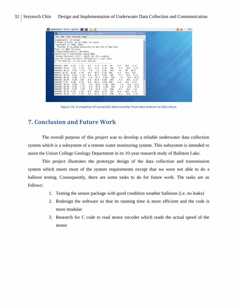
7. Conclusion and Future Work
The overall purpose of this project was to develop a reliable underwater data collection
system which is a subsystem of a remote water monitoring system. This subsystem is intended to
assist the Union College Geology Department in its 10-year research study of Ballston Lake.
This project illustrates the prototype design of the data collection and transmission
system which meets most of the system requirements except that we were not able to do a
balloon testing. Consequently, there are some tasks to do for future work. The tasks are as
follows:
1. Testing the sensor package with good condition weather balloons (i.e. no leaks)
2. Redesign the software so that its running time is more efficient and the code is
more modular
3. Research for C code to read motor encoder which reads the actual speed of the
motor

33 Sreynoch Chin Design and Implementation of Underwater Data Collection and Communication
References
[1] Aug Soe, “Design and Implementation of an RF Data Communication System,” Senior
Capstone Project, Electrical Engineering Department, Union College, Schenectady, 2011.
[2] Stallings, W., Data and computer communication. Pearson Education, Inc., New Jersey, 2004
[3] Silicon Labs. “F8051F34x Data Sheet”
http://www.silabs.com/Support%20Documents/TechnicalDocs/C8051F34x.pdf
[4] Silicon Labs. “Support Document”
http://www.silabs.com/Support%20Documents/TechnicalDocs/C8051F34x-DK.pdf
[5] RobotShop.
http://www.robotshop.com/content/PDF/board-of-education-rev-c-manual-28150.pdf.
[6] Silicon Lab “Suppport Document”
http://www.silabs.com/Support%20Documents/TechnicalDocs/USB-MSD-RD.pdf
[7] Kurose, J. and Ross, K., Computer Networking: A Top-Down Approach. Fifth Edition.
Pearson Education, Inc., Boston, MA, 2010.

34 Sreynoch Chin Design and Implementation of Underwater Data Collection and Communication
Appendix A
/*
Author: Sreynoch
Advisor: Professor James Hedrick
ECE 499: Senior Design Project 2011-2012
This program has two functions. One is to control the motor. Another function is to store data
from the sensor package in the control computer and send the data to the shore computer
Last Updated: 02/01/2012
NOTES: LED P1^6 causes UART 0 to stop working
*/
#pragma CODE
// Include files
#include <c8051f020.h>
#include <stdio.h>
#define FALSE 0
#define TRUE 1
//----------------------------------------------------------
// 16-bit SFE definitions for 'F02x
//----------------------------------------------------------
sfr16 DP = 0x82; //data pionter
sfr16 TMR3RL = 0x92; //Timer3 reload value

35 Sreynoch Chin Design and Implementation of Underwater Data Collection and Communication
sfr16 TMR3 = 0x94; //Timer3 counter
sfr16 ADC0 = 0xbe; //ADC0 data
sfr16 ADC0GT = 0xc4; //ADC0 greater than window
sfr16 ADC0LT = 0xc6; //ADC0 less than window
sfr16 RCAP2 = 0xca; //Timer2 capture/reload
sfr16 T2 = 0xcc; //Timer2
sfr16 RCAP4 = 0xe4; //Timer4 capture/reload
sfr16 T4 = 0xf4; //Timer4
sfr16 DAC0 = 0xd2; //DAC0 data
sfr16 DAC1 = 0xd5; //DAC1 data
/* communications registers for UART 1 - not in hardware file*/
/* UART 1 */
//---------------------------------------------------------
// Global CONSTANTS
//---------------------------------------------------------
#define SYSCLK 22118400 //SYSCLK frequency in Hz
#define BAUDRATE 9600 //Baud rate of UART in bps
sbit LED = P1^6; //LED
sbit POLICE = P2^4; //

36 Sreynoch Chin Design and Implementation of Underwater Data Collection and Communication
sbit motorbrake = P2^0; //Brake
sbit direction = P2^1; //direction
sbit PWM = P2^2; //Pulse Width Modulation
//---------------------------------------------------------
// Function PROTOTYPE
//---------------------------------------------------------
void SYSCLK_Init(void);
void config(void);
void UART0_Init(void);
void UART1_Init(void);
char getUART0Char();
void delay(long i);
void main(void)
{
int alarm;
int counter;
int j;
int i;
char outmsg[20];

37 Sreynoch Chin Design and Implementation of Underwater Data Collection and Communication
char ch;
WDTCN = 0xde; //disable watchdog timer
WDTCN = 0xad;
SYSCLK_Init(); //initialize oscillaor
config();
UART0_Init(); //initialize UART0
UART1_Init(); //initialize UART1
motorbrake = 0;
direction = 0;
PWM = 0;
/*printf("test message\n"); */
for (;;) {
/* get a character from the sensor */
ch = getUART0Char();
/* LED = 1;8?
PWM = 1;
/*delay(25); */
LED = 0;
PWM = 0;

38 Sreynoch Chin Design and Implementation of Underwater Data Collection and Communication
/*delay(50); */
direction = 1;
LED = 1;
PWM = 1;
/*delay(25); */
/*LED = 0;*/
PWM = 0;
/*delay(50); */
direction = 0;
SBUF1 = ch;
} // end for loop
}
/*
wait here until a character is received from UART0
*/
char getUART0Char()
{
char in_char;

39 Sreynoch Chin Design and Implementation of Underwater Data Collection and Communication
for (;;) {
if (RI0 == 1) {
in_char = SBUF0;
RI0 = 0;
return(in_char);
}
}
}
void delay(long i)
{
long j;
long delay_time = i*10000;
for (j = 0; j < delay_time; j++);
}
//---------------------------------------------------------
// Config Routine
//Configured using Silicon Industries Configuration Wizard
//---------------------------------------------------------
void config(void){

40 Sreynoch Chin Design and Implementation of Underwater Data Collection and Communication
//Configure the XBRn Registers
XBR0 = 0x04; //XBAR0: Initial Reset Value
XBR1 = 0x00; //XBAR1: Initial Reset Value
XBR2 = 0x44; //XBAR2: Initial Reset Value
/*Select Pin I/O
Note: Some peripheral I/O pins can functionas either
inputs or outputs, depending on the configuration of the peripheral. By default,
the configuration utility will configure these I/O pins as push-pull putputs
*/
// Port configuration (1 = Push Pull Output)
P0MDOUT = 0x05; //output configuration for P0
P1MDOUT = 0x40; //output configuration for P1
P2MDOUT = 0x0F; //output configuration for P2
P3MDOUT = 0x00; //output configuration for P3
P74OUT = 0x00; //output configuration for P4-7
P1MDIN = 0xFF; //Input configuration for P1
}
/*
initialization subroutines
SYSCLK_Init

41 Sreynoch Chin Design and Implementation of Underwater Data Collection and Communication
This routine initializes the system clock to use an 22.1184 MHz crystal as its clock source
*/
void SYSCLK_Init(void)
{
int i; //delay counter
OSCXCN = 0x67; //start external oscillator with //22.1184 MHz crystal
for (i=0; i<256; i++); //wait for oscillator to start
while(!(OSCXCN & 0x88)); //wait for crystal oscillator to settle
OSCICN = 0x88; //select external oscillator as SYSCLK
//source and enable mission clock
detector
}
/*
UART0_Init
Configure the UART0 using Timer1, for <baudrate> and 8-N-1
UART 0 uses P0 pin 0 for TX and P0 pin 1 for RCV
*/
void UART0_Init(void)
{
SCON0 = 0x50; //SCON0: mode 1, 8-bit UART, enable RX
TMOD = 0x20; //TMOD: Timer1, mode 2, 8-bit reload
TH1 = -(SYSCLK/BAUDRATE/16);//set Time1 reload value for baudrate

42 Sreynoch Chin Design and Implementation of Underwater Data Collection and Communication
TR1 = 1; //start Timer1
CKCON |= 0x10; //Timer1 uses SYSCLK as time base
PCON |= 0x80; //SMOD00 = 1 (disable baudrate divde-by-
two
TI0 = 1; //Indicate TX0 ready
}
/*
UART1_Init
Configure the UART1 using Timer 4, for <baudrate> and 8-N-1
UART 1 uses P0 pin 2 for TX ansd P0 pin 3 for RCV
*/
void UART1_Init(void)
{
SCON1 = 0x50; //SCON1: mode 1, 8-bit UART, enable RX
T4CON = 0x30;
RCAP4 = -(SYSCLK/BAUDRATE/32);
T4 = RCAP4;
CKCON |= 0x40;
PCON |= 0x10;
T4CON |= 0x04;
}