Design and Implementation of the clusterf Load Balancer ... · Design and Implementation of the...
104
Design and Implementation of the Load Balancer for Docker Clusters School of Electrical Engineering
Transcript of Design and Implementation of the clusterf Load Balancer ... · Design and Implementation of the...

Tero Marttila
Design and Implementation of the clusterf
Load Balancer for Docker Clusters
School of Electrical Engineering
Thesis submitted for examination for the degree of Master of
Science in Technology.
Espoo 10.10.2016
Thesis supervisor:
Prof. Raimo Kantola
Thesis advisor:
PhD. Pasi Sarolahti

aalto-yliopisto
sähkotekniikan korkeakoulu
diplomityön
tiivistelmä
Tekijä: Tero Marttila
Työn nimi: Docker-ryppäiden clusterf -kuormantasaajan suunnittelu jatoteutus
Päivämäärä: 10.10.2016 Kieli: Englanti Sivumäärä:7+97
Professuuri: Tietoverkkotekniikka Koodi: S38
Valvoja: Prof. Raimo Kantola
Ohjaaja: FT Pasi Sarolahti
Docker tarjoaa omavaraisia sovelluslevykuvia joita voidaan siirtää eri tietokoneilleja tavan suorittaa kyseisiä sovelluslevykuvia Docker konttien muodostamissa eris-tetyssä sovellusympäristöissä. Konttialustat tarjoavat pilvessä ajettavien skaalau-tuvien sovelluspalveluiden käyttöönottoon vaadittuja peruspalveluita, kuten orke-strointia, verkkoviestintää, palvelinetsintää sekä kuormantasausta.Tämä työ tutkii konttiverkkojen arkkitehtuuria sekä olemassaolevia pilvikuorman-tasaajatoteutuksia luodakseen skaalautuvan Linux IPVS-toteutukseen pohjautu-van verkkotason kuormantasaajan toteutusmallin. Tämä clusterf kuorman-tasaaja käyttää kaksikerroksista kuormantasausmallia joka yhdistää eri kuorman-tasausmenetelmiä saavuttaakkseen sekä skaalautuvuuden että yhteensopivuudenolemassaolevien Docker konttisovelluksien kanssa. Työssä toteutetaan hajautettuohjauspinta joka tarjoaa automaattisen kuormatasauksen Docker konttisovelluk-sille.Tämän clusterf kuormantasausmallin toteutusta arvioidaan erillisessä ym-päristössä mittaamalla Linux IPVS-toteutuksen tarjoama suorituskyky. Tämänclusterf kuormantasaajan skaalautuvuus arvioidaan käyttäen Equal-Cost Multi-Path (ECMP) reititystä sekä IPVS-yhteystilojen synkronointia.Tutkimustyön tuloksena nähdään että verkkotason IPVS kuormantasaaja suo-riutuu huomattavasti paremmin kuin sovellustason HAProxy kuormantasaajasamassa kon�guraatiossa. Tämä clusterf toteutus mahdollistaa myös kuor-mantasaajan skaalautumisen, sallien yhteyksien siirtämisen kuormantasaajaltatoiselle.Nykyinen clusterf toteutus perustuu epäsymmetrisen reitityksen käyttöön,joka onnistuu Ethernet-pohjaisessa paikallisverkoissa. Toteutuksen laajentaminenmahdollistaakseen käyttöönoton erilaisia verkkototeutuksia käyttävien pilvialus-tojen päällä sallisi clusterf-kuormantasaajan käytön osana yleistä konttialustaa.
Avainsanat: Containers, Docker, Cloud, Load Balancing, DSR, NAT, ServiceDiscovery

aalto university
school of electrical engineering
abstract of the
master's thesis
Author: Tero Marttila
Title: Design and Implementation of the clusterf Load Balancer for DockerClusters
Date: 10.10.2016 Language: English Number of pages:7+97
Professorship: Networking Technology Code: S38
Supervisor: Prof. Raimo Kantola
Advisor: PhD. Pasi Sarolahti
Docker uses the Linux container namespace and cgroup primitives to provide iso-lated application runtime environments, allowing the distribution of self-containedapplication images that can be run in the form of Docker containers. Containerplatforms provide the infrastructure needed to deploy horizontally scalable con-tainer services into the Cloud, including orchestration, networking, service discov-ery and load balancing.This thesis studies container networking architectures and existing Cloud loadbalancer implementations to create a design for a scalable load balancer usingthe Linux IPVS network-level load balancer implementation. The clusterf loadbalancer architecture uses a two-level load balancing scheme combining di�erentpacket forwarding methods for scalability and compatibility with existing Dockerapplications. A distributed load balancer control plane is implemented to provideautomatic load balancing for Docker containers.The clusterf load balancer is evaluated using a testbed environment, measuringthe performance the network-level Linux IPVS implementation. The scalabilityof the clusterf load balancer is tested using Equal-Cost Multi-Path (ECMP)routing and IPVS connection synchronizationThe result is that the network-level Linux IPVS load balancer performs signi�-cantly better than the application-level HAProxy load balancer in the same con-�guration. The clusterf design allows for horizontal scaling with connectionfailover between IPVS load balancers.The current clusterf implementation requires the use of asymmetric routingwithin a network, such as provided by local Ethernet networks. Extending theclusterf design to support deployment onto existing Cloud infrastructure plat-forms with di�erent networking implementations would qualify the clusterf loadbalancer for use in container platforms.
Keywords: Containers, Docker, Cloud, Load Balancing, DSR, NAT, Service Dis-covery

iv
Abstract (in Finnish) ii
Abstract iii
Symbols and Abbreviations vi
Aknowledgements vii
1 Introduction 11.1 Research Problems . . . . . . . . . . . . . . . . . . . . . . . . . . . . 21.2 Thesis Structure . . . . . . . . . . . . . . . . . . . . . . . . . . . . . . 3
2 Background 42.1 Docker Containers . . . . . . . . . . . . . . . . . . . . . . . . . . . . 52.2 Orchestration . . . . . . . . . . . . . . . . . . . . . . . . . . . . . . . 62.3 Container Networking . . . . . . . . . . . . . . . . . . . . . . . . . . 8
2.3.1 Ethernet Bridging . . . . . . . . . . . . . . . . . . . . . . . . . 92.3.2 IP Routing . . . . . . . . . . . . . . . . . . . . . . . . . . . . 112.3.3 Network Address Translation . . . . . . . . . . . . . . . . . . 132.3.4 Overlay Networks . . . . . . . . . . . . . . . . . . . . . . . . . 142.3.5 IPv6 . . . . . . . . . . . . . . . . . . . . . . . . . . . . . . . . 16
2.4 Service Discovery . . . . . . . . . . . . . . . . . . . . . . . . . . . . . 162.5 Load Balancing . . . . . . . . . . . . . . . . . . . . . . . . . . . . . . 19
2.5.1 Network-layer load balancing . . . . . . . . . . . . . . . . . . 202.5.2 Network-level load balancing of Transport-layer connections . 212.5.3 Application-level load balancing of Transport-layer connection 242.5.4 Application-layer load balancing . . . . . . . . . . . . . . . . . 242.5.5 DNS . . . . . . . . . . . . . . . . . . . . . . . . . . . . . . . . 25
3 A Study of Docker Container Platform Components 273.1 Docker Networking . . . . . . . . . . . . . . . . . . . . . . . . . . . . 27
3.1.1 Single-Host container networking . . . . . . . . . . . . . . . . 293.1.2 Multi-host container networking . . . . . . . . . . . . . . . . . 32
3.2 Service Discovery . . . . . . . . . . . . . . . . . . . . . . . . . . . . . 353.2.1 etcd . . . . . . . . . . . . . . . . . . . . . . . . . . . . . . . . 353.2.2 SkyDNS . . . . . . . . . . . . . . . . . . . . . . . . . . . . . . 363.2.3 Gliderlabs registrator . . . . . . . . . . . . . . . . . . . . . 373.2.4 confd . . . . . . . . . . . . . . . . . . . . . . . . . . . . . . . 37
3.3 Networking . . . . . . . . . . . . . . . . . . . . . . . . . . . . . . . . 383.3.1 Flannel . . . . . . . . . . . . . . . . . . . . . . . . . . . . . . 383.3.2 Weave . . . . . . . . . . . . . . . . . . . . . . . . . . . . . . . 39
3.4 Load balancing . . . . . . . . . . . . . . . . . . . . . . . . . . . . . . 403.4.1 HAProxy and nginx . . . . . . . . . . . . . . . . . . . . . . . 403.4.2 Vulcand and traefik.io . . . . . . . . . . . . . . . . . . . . . 41

v
3.4.3 Google Maglev . . . . . . . . . . . . . . . . . . . . . . . . . . 413.4.4 Ananta . . . . . . . . . . . . . . . . . . . . . . . . . . . . . . . 433.4.5 Linux IP Virtual Server . . . . . . . . . . . . . . . . . . . . . 45
4 The clusterf Load Balancer 474.1 Design Rationale . . . . . . . . . . . . . . . . . . . . . . . . . . . . . 484.2 Network Architecture . . . . . . . . . . . . . . . . . . . . . . . . . . . 494.3 IPVS Data Plane . . . . . . . . . . . . . . . . . . . . . . . . . . . . . 524.4 Control Plane . . . . . . . . . . . . . . . . . . . . . . . . . . . . . . . 544.5 Con�guration . . . . . . . . . . . . . . . . . . . . . . . . . . . . . . . 564.6 Implementation Challenges and Future Work . . . . . . . . . . . . . . 59
5 Evaluating the clusterf Load Balancer 625.1 Physical Infrastructure . . . . . . . . . . . . . . . . . . . . . . . . . . 625.2 Virtual Infrastructure . . . . . . . . . . . . . . . . . . . . . . . . . . . 655.3 Docker Infrastructure . . . . . . . . . . . . . . . . . . . . . . . . . . . 675.4 Measurement Tools . . . . . . . . . . . . . . . . . . . . . . . . . . . . 685.5 Load Balancing . . . . . . . . . . . . . . . . . . . . . . . . . . . . . . 695.6 Load Measurements . . . . . . . . . . . . . . . . . . . . . . . . . . . . 71
6 Results and Analysis 746.1 Challenges . . . . . . . . . . . . . . . . . . . . . . . . . . . . . . . . . 756.2 Connection Routing . . . . . . . . . . . . . . . . . . . . . . . . . . . . 76
6.2.1 DNS Service Discovery . . . . . . . . . . . . . . . . . . . . . . 766.2.2 Application-level proxying . . . . . . . . . . . . . . . . . . . . 776.2.3 Network-level forwarding . . . . . . . . . . . . . . . . . . . . . 786.2.4 Network-level forwarding with port translation . . . . . . . . . 78
6.3 Baseline Measurements . . . . . . . . . . . . . . . . . . . . . . . . . . 796.3.1 Local container network . . . . . . . . . . . . . . . . . . . . . 796.3.2 Intra-cluster . . . . . . . . . . . . . . . . . . . . . . . . . . . . 806.3.3 Inter-cluster symmetric routing . . . . . . . . . . . . . . . . . 836.3.4 Inter-cluster multipath routing . . . . . . . . . . . . . . . . . . 84
6.4 Comparing Implementation Performance . . . . . . . . . . . . . . . . 856.4.1 The HAProxy application-level load balancer . . . . . . . . . . 856.4.2 The IPVS network-level load balancer . . . . . . . . . . . . . . 86
6.5 Scaling the clusterf Load Balancer . . . . . . . . . . . . . . . . . . 876.5.1 ECMP routing for a single VIP . . . . . . . . . . . . . . . . . 886.5.2 Connection failover for a single VIP with ECMP routing . . . 89
6.6 Analysis . . . . . . . . . . . . . . . . . . . . . . . . . . . . . . . . . . 90
7 Conclusions 92
References 95

vi
Symbols and Abbreviations
BGP Border Gateway ProtocolDHCP Dynamic Host Con�guration ProtocolDNS Domain Name SystemDNAT Destination Network Address Translation (NAT)DSR Direct Server Return (load balancing)ECMP Equal-Cost Multi-Path (routing)HTTP HyperText Transfer ProtocolIaaS Infrastructure as a ServiceICMP Internet Control Message ProtocolIP Internet ProtocolIPv4 Internet Protocol Version 4IPv6 Internet Protocol Version 6LVS, IPVS Linux Virtual Server, IP Virtual Server (Linux)NAT Network Address TranslationOSPF Open Shortest Path FirstPaaS Platform as a ServiceRFC Request For Comments (IETF)SaaS Software as a ServiceSNAT Source Network Address Translation (NAT)TCP Transport Control ProtocolTLS Transport Layer SecurityUDP User Datagram ProtocolVIP Virtual IPVRRP Virtual Router Redundancy ProtocolVXLAN Virtual eXtensible LAN

vii
Aknowledgements
I would like to thank Prof. Jörg Ott for providing me with the time and resourcesnecessary to study Docker container platforms and develop the clusterf load bal-ancer at the Aalto University Department of Communications and Networking.
I would like to thank my parents and family for their support in getting me to sitdown and actually write this thesis, from the �rst few pages to the very last weekof editing.
I would like to thank my supervisor Prof. Raimo Kantola and advisor PhD. PasiSarolahti for their comments and review of my thesis text.
I would like to thank my colleague at Comnet MSc. Arseny Kurnikov for theirsupport in the implementation and testing of the clusterf load balancer.
This work was supported by the Academy of Finland project "Cloud Security Ser-vices" (CloSe) 1 at Aalto University Department of Communications and Network-ing.
Otaniemi, 09.10.2016
Tero Marttila
1https://wiki.aalto.fi/display/CloSeProject/

1 Introduction
Cloud computing can be de�ned as the combination of three di�erent service mod-els: Infrastructure as a Service (IaaS), Platform as a Service (PaaS), and Softwareas a Service (SaaS) [1]. An IaaS Cloud uses Virtual Machines (VMs) to allocateand share physical machine resources between multiple operating systems by vir-tualizing low-level resources such as disk controllers, network interface cards andbootloaders. The provider of an IaaS Cloud platform controls both the physicalnetwork and server infrastructure. A PaaS Cloud provides a high-level applicationenvironment including the tooling and infrastructure required to provide softwareapplications and services in the Cloud (SaaS). Application containers can be usedas the foundation of such a platform for horizontally scalable cloud services. Con-tainer platforms designed to be portable across di�erent infrastructures can be usedfor the local development of cloud applications and deployment onto cloud serverinfrastructures.
Containers allocate and share operating system resources between multiple pro-cesses by virtualizing high-level resources such as process management interfaces,the TCP/IP network stack, or the �lesystem namespace. Mature container-basedplatforms such as Google's Borg [2] demonstrate the strengths of containers whenoperating cloud services at large scales. Google Borg is the primary container plat-form used to deploy thousands of di�erent applications across clusters of tens ofthousand of servers within the Google infrastructure [2]. Google Borg is used torun a wide variety of applications in the form of containers, including end-user fac-ing services such as Gmail and Google Web Search, infrastructure services such asBigTable, and batch-processing infrastructure such as MapReduce [2].
The history of mature container-based platforms such as Google Borg can be tracedback to the implementation of shared resource isolation primitives for optimizingserver resource utilization [2]. Critical production services require the reservation ofsu�cient resources for handling peak loads, leading to poor resource utilization dur-ing idle periods. Robust resource isolation primitives allow these idle resources to beused by lower-priority batch jobs that are insensitive to latency and can be quicklypreempted on demand [3]. However, the development and deployment of servicesin the form of distributed applications requires systems to support their manage-ment and operation. The rapid evolution of support services within Google's Borgecosystem demonstrated the applicability of the application container abstraction formore than just managing shared resources. Over time, the nature and signi�canceof these early container-based platforms expanded, forming an Application-orientedInfrastructure platform [4].
Docker is an open-source Linux container management system that is rapidly gain-ing adoption in the development of Cloud applications [5]. Docker emphasizes theapplication-oriented aspect of containers, with containers being used to operate in-dividual applications rather than opaque virtual machines. Docker Images can be

2
used to package applications into a single easily distributable image, including allruntime resources and dependencies. Docker combines the ease of building Dockerimages when developing applications with the �exibility of running Docker Contain-ers when deploying applications. Docker Containers provide an isolated runtimeenvironment for each application, such that the application images do not need toinclude any low-level components such as disk management or network con�gura-tion. The Application Container model simpli�es the deployment of applications byproviding an abstraction layer where Docker manages the infrastructure resourcessuch as the storage and network. The Docker Engine can be used to deploy anyapplication developed as a Docker Image onto any developer machine or cloud servercon�gured to run Docker Containers.
While Docker presents a solution for many of the problems related to applicationdevelopment, deploying container-based applications into the Cloud requires thesupport of a container-oriented cloud infrastructure platform [6]. An Application-oriented Infrastructure platform [4] supports the development and deployment of dis-tributed cloud-native applications, allowing them to scale horizontally in the Cloud.Such an application infrastructure platform requires numerous components, includ-ing a container engine for running applications, an orchestration system to managecontainers, a service discovery mechanism to allow containers to communicate acrossthe network, and a load-balancing layer to distribute tra�c across multiple serviceinstances.
1.1 Research Problems
The objective of this work is the implementation of a scalable network-layer load-balancer within the scope of a cluster of machines running Docker applications.Docker container networking concepts and existing implementations of cloud loadbalancers such as Google Maglev [7] and Microsoft Ananta [8] are studied to con-struct a design for a scalable network-level load balancer using Linux IPVS. Weimplement the clusterf control plane to integrate this network-level load balancerdesign with Docker, providing automatic load balancing for container services withina Docker cluster. The research questions for this work are:
• Do network-level load balancing methods have scalability advantages overapplication-level load balancing methods?
• How is the design of a network-level load balancer determined by the networkarchitecture?

3
1.2 Thesis Structure
This work is structured as follows. Chapter 2 presents a theoretical model for acontainer platform with a focus on container networking, discussing orchestration,service discovery and load balancing methods. Chapter 3 studies various implemen-tations of Docker container platform components, focusing on components relevantto networking and load balancing. Chapter 4 presents the implementation of theclusterf load balancer for Docker clusters, using a design for a scalable network-level load balancing based on the Linux IPVS implementation discussed in Section3.4.5. Chapter 5 discusses the methods used to evaluate the design and implementa-tion of the clusterf load balancer, presenting and analyzing the results in Chapter6. Finally, we conclude with Chapter 7, answering our research questions based onthe design work in Chapter 4 and the results in Chapter 6.

4
2 Background
The dynamic nature of Cloud computing leads to changes in application design [9]when scaling an application from a developer's machine to a service with millionsof users. For a traditional application running on a single machine, vertical scal-ing involves upgrading the machine for improved performance and reliability. Thevertical scaling approach keeps the application software simple, but it is ultimatelylimited by the cost of su�ciently powerful and reliable hardware. Cloud infrastruc-ture uses a di�erent approach, running large numbers of commodity server machinesoptimized for cost and e�ciency over reliability. For a distributed application capa-ble of running across multiple machines, horizontal scaling involves increasing thenumber of machines for improved performance and reliability.
Horizontal scaling of a service involves additional complexity due to the need for adistributed systems design. Increasing the capacity of the service requires a methodfor dynamically distributing load across multiple instances, allowing the addition ofmore instances to increase capacity. However, increasing the number of independentinstances also means that it is more likely for some instance to fail. Horizontalscaling also requires a fault tolerance mechanism to maintain the reliability of theservice. Any cloud service running only a single instance is limited in terms of bothperformance and reliability.
This Chapter provides an overview of container platform infrastructure componentsthat ease the development of horizontally scalable applications using containers.Containers provide isolated runtime environments for application, allowing the useof self-contained application images and immutable infrastructure for determinis-tic deployments. Container network allows container applications running within acluster of machines to connect to services exposed by other containers within thesame cluster, while also allowing those containers to be run on any networked ma-chine. Service discovery allows container applications to resolve the current networklocation of a service, even as new containers providing the service are started, orold ones are removed. Load balancing allows the deploying of horizontally scalableapplications, distributing processing workload across multiple service instances.
A design for a generic container platform allows application architectures devel-oped in the form of application containers on a local machine to be deployed acrossheterogneous cloud platform infrastructures. The design of a generic container plat-form must allow for implementation di�erences across di�erent local developmentenvironments and cloud infrastructure platforms. These di�erences are particularlyapparent in the design of container network architectures, requiring the use of tech-niques such as Network Address Translation (NAT) and overlay networking.
Using a container platform as an abstraction layer for the deployment of cloud ap-plications allows the use of cloud infrastructure services as commodity resources,easing the portability of cloud service deployments across competing cloud infras-

5
tructure providers. Applications dependent on speci�c cloud infrastructure serviceswithin a cloud provider's platform lead to cloud vendor lock-in. [10]
2.1 Docker Containers
Containers can be considered as a lightweight alternative to virtual machines, shift-ing the virtualization layer from low-level machine resources to the virtualization ofoperating system resources. Containers extend the typical multi-processing model ofoperating systems to further isolate groups of processes by virtualizing their view ofsystem resources such as the process management interfaces, the TCP/IP networkstack, or the �lesystem namespace. Processes executing within di�erent containersall share the same operating system kernel, but cannot see resources outside of theircontainer.
Docker is a container management tool which provides an image format for dis-tributing self-contained application bundles, and a container runtime for executingthe application images within isolated runtime environments using Linux containers[11]. Docker's philosophy of Application Containers di�ers from traditional containermanagement systems in that Docker containers are designed to execute individualapplications, rather than a traditional operating system. The Docker Engine ini-tializes each container with pre-con�gured runtime environment, allowing the useof minimal application images as small as a single statically built binary. Dockerapplication Images are designed to be portable across di�erent machines and infras-tructures, providing a consistent runtime environment whether run on a developermachine or on cloud servers.
Docker's images are designed to be self-contained application bundles that can bedistributed and run on any architecture-compatible Linux machine without anydependencies on the host environment. Images are built from a source-languageDockerfile �le format which describes the base image to extend, and the executionsteps used to set up the desired environment within the container. Each image alsoincludes metadata about the runtime environment for the container, including theapplication command line to run within the container, additional �lesystem volumesto mount for storing data, network TCP/UDP ports exposed by the service, andadditional metadata labels. The application runtime interface provided by Docker isthat of a generic UNIX process, meaning environment variables and an executablebinary with arguments (or shell command). This avoids the need to impose anyrequirements for the use of a speci�c application-level framework, and maintainscompatibility with existing applications intended to be run as UNIX services.
On Linux, Docker uses the kernel's cgroup [12] and namespace [13] facilities tocreate an isolated environment for the container. Linux cgroups are mainly usedto manage resource limits for contained processes, whereas the di�erent namespacesvirtualize various aspects of the runtime environment. The Mount namespace is used

6
to present a copy of the Docker image as the root �lesystem for the container, aswell as internal system mounts and optional persistent data volumes. The Networknamespace is used to create and con�gure a separate in-kernel networking contextfor the container, including an isolated set of network interfaces, IP routing tables,net�lter �rewall rules, and TCP/UDP ports.
Docker's Application Containers philosophy is evident in the way that these names-paces are con�gured and managed. Both the mount and network namespaces arefully initialized and con�gured by Docker when creating the container, and thusthe application images can be kept free of any infrastructure-speci�c artifacts suchas bootloader or network con�guration. The Docker engine also provides facilitiesfor the administration, centralized logging and monitoring of application contain-ers, avoiding the need for running auxilliary components such as traditional SSH orSyslog daemons within each container.
The behavior of Docker's �lesystem namespaces is also related to various aspects ofapplication design that arise when developing applications for deployment on cloudinfrastructure [9]. Docker's container runtime environment is designed to give eachcontainer a private and ephemeral copy of the image: any changes to �les in theDocker image are invisible to other containers, and are discarded when the containeris restarted. Immutable Infrastructure means that rather than modifying the �lesincluded in the image, the running container is replaced with a new container runningan updated version of the image. Infrastructure as Code means that the updatedimages are built from the modi�ed Docker�le, which can be managed as code using aVersion Control System. Applications must therefore enforce a separation betweencode and data, by con�guring explicit data volumes for any �les written by theapplication. Docker can then provide various infrastructure-speci�c volume driversto provide persistence for these data volumes across container restarts.
2.2 Orchestration
When moving from application development to operating a production service, per-formance and reliability requirements can quickly grow beyond the scale of a singlemachine. Where an operating system manages the tasks running on a single ma-chine, orchestration manages the tasks running across an entire cluster of machines:a distributed operating system.
The Mesos [14] platform is an example of an orchestration system that serves as afoundation for the Mesosphere DC/OS distributed operating system. Both ApacheMesos and Google Borg [4] share a common motivation of e�ciently sharing ma-chine resources between di�erent kinds of distributed applications. Both systemsreplaced speci�c distributed batch processing frameworks (Google's Global WorkQueue and Apache's Hadoop) with more general mechanisms suitable for runningother workloads such as latency-sensitive production services. Whereas Google Borg

7
is a monolithic system with a single master and agent process, Apache Mesos decom-poses the system into a minimal master reponsible for resource allocation, externalschedulers and modular executors. A scheduler is responsible for assigning tasks tomachines, and an executor is responsible for executing tasks in an isolated environ-ment. Di�erent Mesos frameworks can then provide optimal scheduling strategiesand execution environments for di�erent workloads sharing a cluster of machines.
Clusters consist of large numbers of machines interconnected by a network. BothBorg [4] and Mesos [14] discuss cluster sizes on the order of tens of thousands ofmachines. The orchestration system consists of a central master for the cluster, andan agent process on each machine. The agents register with the master, which main-tains a registry of available machines and their resources, in terms of quantities suchas CPUs, memory and disk. To execute tasks, the master provides a managementinterface for users to submit job speci�cations, which de�ne the characteristics andresource requirements of the tasks to execute. The master schedules the job onto aset of machines matching the job's constraints, and hands the job over to the ma-chine agents for task execution. The machine agent then executes each task, usingan isolation mechanism such as Linux containers to enforce the resource allocationfor di�erent tasks sharing the same machine. The machine agent must also track thelifetime of the task, in order to release its resources for further use once it exits. Themaster must deal with unexpected changes to jobs, such as task failure or machinefailure.
The speci�c scheduling requirements for an orchestration system vary dependingon the di�erent kinds of workloads being run. Batch processing workloads such asHadoop can be optimized using data locality in order to minimize inter-machinenetwork tra�c. When the input dataset for a job is distributed across disk storageon the cluster machines, tasks should ideally be run on the same machine that theirslice of the input dataset is stored on. For batch-processing pipelines, the schedulermust also be aware of task completion in order to start further jobs which dependon the output of the completed task. For long-running production services, supportfor runtime support con�guration changes to existing jobs is highly desireable, suchas rolling upgrades to individual tasks to minimize service downtime.
The task execution environment is fundmental in achieving the dual bene�ts ofperformance scalability combined with e�cient resource utilization, which relies onisolation between mixed-priority tasks sharing machine resources. Critical produc-tion services that handle network requests are highly latency-sensitive, while batchprocessing workloads are generally insensitive to latency and considered best-e�ort.High-priority production services must be scheduled with su�cient guaranteed re-sources to handle peak load, which leaves signi�cant amounts of resources under-utilized during idle periods. With an execution environment capable of providingsu�ciently strict task isolation and scheduling, this otherwise idle capacity can beutilized by overcomitted resources for lower-priority tasks, which can be preemptedunder higher-priority task load spikes [4].

8
Both Apache Mesos and Google Borg use a task execution environment based onLinux containers with their cgroup [12] features to provide the necessary performanceisolation. Using Linux containers with their namespace [13] features also solvesthe operational aspects of executing tasks on di�erent machines, as the semanticsprovided by application containers align closely with the concept of a workloadunit to be scheduled onto a cluster of machines. Container images provide theapplication portability needed to transparently execute arbitrary applications onarbitrary machines.
2.3 Container Networking
Container platforms using Linux network namespaces allow each container to behaveas a virtual network host with independent network interfaces, IP addresses, routesand TCP/UDP port numbers. Providing each application container with its ownnetwork identity can be considered a design requirement for a container platform[4]. This requirement is discussed in more detail in Section 2.4 on Service Discovery,considering the additional complexity introduced by sharing a common TCP/UDPport space between di�erent containers.
Figure 1: Minimalist container networking architecture, with the host machine inblue, and the virtual container network in green.
The minimalist container networking architecture shown in Figure 1 contains theminimum of networking components used to allow containers to communicate. Thehost machine is used to run multiple Docker containers, as discussed previouslyin Section 2.1 on Docker Containers. A virtual container network is created, us-ing a virtual Ethernet bridge (docker0) as described in Section 2.3.1 on EthernetBridging. The container network uses a subnet of Internet Protocol (IP) networkaddresses to allow each container having an individual network address to commni-cate, as described in Section 2.3.2 on IP Routing. Expanding the container networkto communicate with other machines outside the container platform typically usesNetwork Address Translation (NAT), as described in Section 2.3.3 on NAT. Ex-panding the container network to communicate with container networks on other

9
machines within the container platform typically uses overlay network tunnels, asdescribed in Section 2.3.4.
Container platforms designed to scale from a single developer machine to a horizon-tally scalable cloud deployment must consider many di�erent scenarios, including adeveloper's machine roaming between di�erent networks, a variety of cloud infras-tructures, or a dedicated network designed for container workloads. The networkabstractions exposed to the application containers must remain independent of theinfrastructure used to run the containers. A network implementation must not arbi-trarily limit the number of containers that can be run on a machine, such as requiringa DHCP lease on the machine's local network for each container. It should also bepossible to run the same service as a single container on a development machine, oras large number of horizontally scaled instances scheduled to run on multiple cloudservers.
2.3.1 Ethernet Bridging
A link-layer Ethernet network consists of Ethernet interfaces connected using eithera point-to-point link or an Ethernet bridge to forward packets between multiple links.Ethernet networks use a �at address space with 48-bit Ethernet addresses, whereany Ethernet address may be used anywhere within the network. Each Ethernetinterface connected to the network must have a unique Ethernet address, whichare typically pre-assigned when the interface is created. Ethernet networks aremodeled as a shared broadcast domain where each transmitted packet is potentiallyreceived by all connected interfaces, with spurious packets being discarded. Ethernetpackets sent to the broadcast destination address are processed by all interfaces, andprovide a means for a host to discover other connected interfaces. The advantage ofEthernet networks is in their simplicity and �exibility, as interfaces can be attached,detached or moved within the network without the need for any recon�guration.[15, Section 4.3]
Ethernet bridges can minimize �ooding by only forwarding unicast tra�c to theport closest to the destination, but this requires every bridge on the network tolearn all connected interface Ethernet addresses. Ethernet packets sent to unknownaddress or the broadcast address are �ooded to all connected links. The volume ofbroadcast tra�c and the requirement for each bridge to have global knowledge ofall connected interfaces limits the ultimate scalability of Ethernet networks. Thestandard broadcast �ooding algorithm always requires a loop-free topology, requiringall tra�c across the network to share the same spanning tree of links. [15, Section 4.7]
Traditional machine-level virtualization uses a physical machine to run a virtual-ization hypervisor, virtualizing the physical machine's resources for use by multiplevirtual machines. Virtual machines generally use Ethernet as the networking inter-face between the hypervisor and virtual machine. The hypervisor exposes a virtual

10
Ethernet interface to the virtual machine. The virtual machine's operating systemuses the virtual Ethernet interface to send Ethernet packets, which are processed bythe hypervisor. A common con�guration is to use a virtual Ethernet bridge withinthe hypervisor to forward tra�c between the machine's physical Ethernet interfaceand the internal virtual machine Ethernet links, forming a single Ethernet networkspanning both virtual and external machines.
Linux container networking is generally also implemented using virtual veth Ether-net interface pairs forming a virtual point-to-point link. A newly created networknamespace only contains the default loopback device, and processes running withinsuch an empty network namespace will not have any network connectivity. Whencreating a new container, a pair of veth interfaces is created, and one of the pairednetwork interfaces is moved into the container's network namespace. The remainingveth interface is typically attached to a virtual Ethernet bridge on the host ma-chine. This con�guration forms a internal virtual Ethernet network within the host,allowing containers to communicate with other containers and the host machine.[16]
It is also possible to connect containers to an external Ethernet network. As invirtual machine networking, the machine's external network interface can be at-tached to the virtual Ethernet bridge used for container networking. Alternatively,Linux allows the creation of virtual vlan, macvlan and ipvlan devices for a net-work interface, which can be moved into the container's network namespace. Theuse of macvlan devices can provide signi�cant performance advantages over the useof veth interface pairs with a virtual bridge [17]. However, this requires that theexternal Ethernet network allows the use of multiple virtual Ethernet addresses forpackets forwarded across the external network interface. Using Ethernet networkingtechniques such as macvlan for container networking on cloud virtual machines isnot always possible: [16]
Kubernetes is unable to use MACVLAN since most software de�ned net-works (including Google Compute Engine's) don't support this option.
Using Ethernet bridging for virtual machine networking has the bene�t of allowingthe use of live migration. Live migration allows a running virtual machine to bemoved between di�erent physical machines within the same virtualization clusterwithout restarting the virtual machine or changing the virtual machine's networkaddress. A virtualization cluster supporting live migration requires a shared net-work infrastructure, allowing the virtual machine's Ethernet network interface to bereattached to a di�erent location within the cluster network. Containers generallydo not support live migration, and any method of migrating a container from onemachine to another involves restarting the container. Container platforms used todeploy horizontally scaled applications can use dynamic service discovery and load-balancing, dynamically routing tra�c for container services to service instances withdynamic network addresses within the cluster.

11
2.3.2 IP Routing
Network-layer IP routing di�ers from Ethernet networks in the use of a hierar-chial addressing scheme, where hosts are assigned addresses based on their locationwithin the network. Global IP addresses are allocated in large chunks for use by anAutonomous System (AS), which may be further subdivided into smaller subnetsroutable by routers within the AS. Each AS presents a coherent routing policy toneighboring AS routers, whereby routers in a di�erent AS do not need to be awareof the interior network structure. The use of hierarchially assigned network addresspre�xes allows IP networks to scale to the size of the Internet by aggregating therouting information for large quantities of individual host addresses into a single�xed-length routing entry. The use of global IP addresses requires each attachedhost to be con�gured with a unique IP address allocated and routed by the networkit is connected to. [15, Section 5.6.2]
IP network addresses are allocated and routed based on a bitwise pre�x, which canbe represented using the Classless Inter-Domain Routing (CIDR) address notation.The CIDR network pre�x 192.0.2.0/24 matches all 32-bit IPv4 addresses witha 24-bit pre�x matching 192.0.2.0, covering 256 addresses from 192.0.2.0 to192.0.2.255. [15, Section 5.6.2]
IP network packets between hosts are forwarded over a link-layer protocol suchas Ethernet. Each Ethernet interface on a network host is con�gured using a lo-cal address and subnet mask, which can be expressed using the CIDR notation192.0.2.100/24. IP hosts use the Address Resolution Protocol (ARP) to resolvethe Ethernet address of IP hosts connected to the same network [15, Section 5.6.3].The host will send an ARP query on that interface for any destination address within192.0.2.0/24, using the Ethernet broadcast destination address and the local IPsource address 192.0.2.1. Hosts connected to an Ethernet network will respond toqueries for their con�gured interface address, returning an ARP reply using unicastEthernet addresses. Communication between IP hosts connected to the same Eth-ernet network is straightforward, assuming that all hosts have a matching interfaceroute and use source addresses within the network pre�x.
An IP router with multiple interfaces connecting di�erent networks must be capableof forwarding incoming packets between interfaces. IP routers use a set of con�guredrouting rules to forward packets with a matching IP destination address via thecorrect interface and link-level destination. Each routing rule contains the CIDRpre�x for matching the destination address, the outbound interface and the next-hopaddress. The routing table can contain multiple overlapping routes for an address,and the route with the longest matching pre�x is used. A default route of 0.0.0.0/0matches all destination addresses that do not have a more speci�c route.
An IP host with a single network interface and IP network address only needs toprocess packets associated with its own local address, requiring a minimal routing

12
table. A machine being connected to a network uses a mechanism such as DynamicHost Con�guration Protocol (DHCP) to con�gure the local interface address androutes [15, Section 5.5.3]. A DHCP client on the machine uses Ethernet broadcastmessages to request a DHCP lease from a DHCP server attached to the Ethernetnetwork, which allocates an appropriate IP address within the network for use bythe client. The DHCP lease will contain the IP address used to con�gure the localinterface, a subnet mask used to con�gure the interface route for the local network,and a default gateway used to con�gure a default route for reaching all other IPdestinations outside of the local network. Di�erent con�guration methods can beused for virtual machines in cloud environments, but the resulting IP host routingis generally similar.
The scalability of IP networks relies on the centralized allocation of network ad-dresses, which comes at the cost of requiring explicit mechanisms for allocatingaddresses and con�guring routing rules. Each IP host must be allocated a uniqueIP address within the local network, each local network must be allocated a uniquesubnet within the AS, and each AS must be allocated a unique network within theInternet. For two hosts connected to di�erent IP networks to communicate, theymust both use appropriate local address routable by every IP router on the path be-tween the endpoints. If a host attempts to use an inappropriate local source address,any reply packets will not be routed back to the host.
Routers use routing control protocols to exchange routing information, originatinglocal routes and propagating routes advertised by other routers. Routers withinan AS will generally use an interior routing protocol to exchange speci�c routes foreach network within the AS, ensuring optimal routing for packets within a reasonablysized network. Routers in di�erent ASs will use the Border Gateway Protocol (BGP)to originate aggregated routes for their interior networks, and propagate routeradvertisements from other ASs. [15, Section 5.5.6]
In order for a router to provide IP connectivity to hosts on a local network, a networksubnet must be allocated and advertised for routing. While DHCP can be used toautomatically allocate individual addresses for hosts within an Ethernet network,using ARP to providing zero-con�guration routing, no similar IPv4 protocol existsfor automatically allocating entire network subnets for use by a router. The limitedavailability of IPv4 addresses makes it di�cult to provide any dynamic mechanismsfor address allocation, and the additional complexity of dynamic routing is rarelyneeded outside of carrier and dedicated server networks. The IPv4 access networksat the edge of the Internet are thus typically con�gured to only provide host-levelconnectivity, lacking any option for a host to upgrade itself into a network router,providing IP network connectivity for multiple local virtual machines or containers.

13
2.3.3 Network Address Translation
Network Address Translation (NAT) allows an IP router to use normal host con�g-uration mechanisms such as DHCP for external network con�guration, while alsoproviding routing for an internal network of hosts. NAT avoids the requirement forallocating globally routable addresses by introducing a separate internal network ad-dress space. NAT avoids the requirement for neighboring routers to have any routesfor the internal network addresses by modifying the packets being forwarded, usingthe external network host source address when forwarding packets to the externalnetwork. A NAT router can operate using a single external network address, whileallowing the use of arbitrary private RFC1918 [18] address space on the internalnetwork. [19]
Compared to the stateless nature of IP routing, where every packet contains suf-�cient header information to be forwarded independently of other packets, NATrouting is stateful. When an outgoing packet from an internal network host is for-warded by replacing the internal source address with the external network address,the incoming reply packet on the external network interface will not contain theinternal network address of the originating host. Sharing the same external net-work address for all outgoing packets requires the NAT router to use additionaltransport-layer header information from incoming packets to determine the internalnetwork destination address for forwarding. Whereas the NAT router must be ableto determine the internal network host address from the incoming packet's 5-tuple ofnetwork-layer addresses and transport-layer port numbers, the same transport portnumber space is also used independently by each internal network host. NAT isthus closely tied to transport-layer client-server semantics, using SNAT techniquesfor clients, and DNAT techniques for servers.
Source NAT (SNAT) is used for internal network clients establishing connections toexternal network servers, sharing the NAT router's external network source address.Each internal network host will independently choose an ephemeral source port forthe outgoing connection, and di�erent internal network hosts may use overlappingsource ports for connections to the same external server and port. The NAT routerwill create a connection state recording the internal network host address associatedwith each outgoing 5-tuple, also rewriting the source port as necessary to guaranteeunique 5-tuples. The 5-tuple of each incoming packet will be compared with the con-nection state table, and an incoming packet matching a recorded state entry will berewritten to the corresponding internal network host address and port. SNAT rout-ing is transparent to internal network hosts behaving strictly as clients, where theNAT router is able to use and record a unique 5-tuple for each outgoing connection.SNAT does not generally allow internal network hosts to act as servers acceptingconnections from unkonwn external clients, as an SNAT router will generally discardincoming packets for unknown 5-tuples.
Destination NAT (DNAT) can be used to expose internal network servers by al-

14
locating speci�c ports to forward incoming connections to an explicitly con�guredinternal network host. DNAT implementations generally also allow rewriting theinternal destination port, allowing the use of multiple distinct external ports to for-ward connections to multiple internal hosts using the same internal destination port.The use of DNAT requires a con�guration mechanism for allocating and con�guringthe port-forwarding rules, which is problematic in cases where the NAT router andthe internal host machines are in di�erent administrative domains.
The stateful nature of NAT routing complicates the design of a scalable networkarchitecture where the capacity or reliability requirements preclude the use of a singlerouter for a given set of internal hosts. When distributing packets between multiplerouters, the same router must be used for both the initial connection packet and thereverse path. Only the router having forwarded the initial packet for a connectionwill have the state required to translate any further packets associated with the sameconnection, including any reply packets. Any fault-tolerance mechanism requires theNAT connection states to be synchronized between machines, as a restarted NATrouter will lose all connection states. Any connections being redirected to a di�erentNAT router lacking the connection state will be cut, forcing clients to reconnect.NAT is best used as close to the edge of the network as possible, limiting the resultingscalability bottlenecks.
Container networking engines designed to run containers on a single machine canuse NAT to create an internal network for use by containers. Using NAT allows ahost machine to provide internal network connectivity for multiple virtual networkhosts without requiring support for address allocation and routing within the exter-nal network. The separate internal network address space introduced by NAT givesthe virtualization platform the �exibility to manage the internal network addressesas required. The concept of separate internal and external connectivity also �ts wellwith the concept of internal and externally exposed services. Virtual network hostswithin the same internal network are able to communicate freely using their inter-nally assigned internal network address. The virtualization platform can provide anintegrated mechanism for the con�guration of DNAT rules for exposing services onthe external network address.
2.3.4 Overlay Networks
NAT allows the use of internal network address space within a single machine with-out exposing the internal network addresses to the external network. Overlay net-works allow the use of internal network address space across multiple machineswithout exposing the internal network addresses to the external network. Tradi-tional networking methods require a network infrastructure capable of forwardinginternally addressed packets between machines, using a link-layer network intercon-nect capable of forwarding packets with arbitrary internal addresses. Cloud IaaSplatforms may provide a separate internal network between virtual machines within

15
a datacenter, but large cloud platforms typically use custom Software De�ned Net-working (SDN) implementations. These SDN implementations may either requirethe use of platform-speci�ed network addresses, or require explicit con�gurationusing a platform-speci�c method.
Overlay networks form virtual network links between machines using a packet tun-neling protocol to encapsulate packets for transport across an external network.When forwarding a packet between internal network addresses on two di�erent ma-chines, a new packet is constructed using the external network addresses of the ma-chines, having the internal packet as the payload. The external network infrastruc-ture forwards the tunnel packet to the destination machine, which de-encapsulatesand forwards the internal packet. The external network only inspects the outerpacket headers containing external machine addresses, and does not inspect the in-ternal network packet. The tunneling protocol may encrypt the inner packet payloadto protect the internal network from packet inspection or spoo�ng.
Overlay tunnels can be used to forward either link-layer or network-layer packets.Network-layer tunnel are used to route IP packets between machines, forming an IProuting domain connecting virtual IP networks on multiple machines. A network-layer overlay network can allocate a subnet for use by the virtual network hosts oneach machine, allowing the use a single routing rule per machine. Link-layer tun-nels are used to bridge Ethernet packets between machines, forming larger Ethernetnetworks connecting virtual Ethernet hosts on multiple machines. A link-layer over-lay network can use network addresses within the same IP network across di�erentmachines, requiring the use of a forwarding rule per virtual Ethernet host.
Virtual eXtensible LAN (VXLAN) is a link-layer overlay networking protocol us-ing UDP to transport Ethernet packets over IP unicast and multicast. VXLAN isdesigned for large-scale networking of virtual machines in a physical multi-tenantinfrastructure, using IP multicast to implement broadcast �ooding and learning sim-ilar to a standard Ethernet bridge. The Linux kernel includes an implementationof VXLAN, using either IP multicast for dynamic learning, or a userspace controlplane. VXLAN can be used as an alternative to custom tunneling protocols usedin userspace implementations of overlay networking, where the in-kernel VXLANswitch o�ers a reduced packet forwarding overhead. The multicast-based VXLANcontrol plane can be replaced using a userspace control plane for use with network in-frastructure that does not support multicast. Securing the VXLAN tunnels withoutthe use of a dedicated infrastructure network providing strict access control requiresthe use of IPSec to secure tunneled packets forwarded over untrusted networks.
An overlay network using packet encapsulation must consider the link-layer Maxi-mum Transmission Unit (MTU), which limits the maximum size of a transmittedpacket including all headers and payload [15, Section 5.5.7]. The packet payloadmust �t into the link MTU after prepending any headers, or the payload must befragmented into multiple smaller packets. Any protocol tunneling packets across an

16
external network using the same default Ethernet MTU as the internal network willlead to fragmentation, as a su�ciently large internal packet will no longer �t into theexternal network MTU after adding the encapsulation headers. Tunneling protocolsgenerally avoid the use of fragmented packets, preferring the use of a su�cientlysmall MTU on the internal network. Determing the correct MTU for the internalnetwork can be di�cult if the external network MTU is unknown. For example, theVXLAN protocol does not support the use of fragmented packets, and recommendsincreasing the external network MTU instead [20, Section 4.3].
2.3.5 IPv6
The IPv6 protocol is designed to address the limitations of IPv4, with a larger128-bit address space o�ering new possibilities for address allocation and routingmechanisms [15, Section 5.6.8]. Where IPv4 networks use mechanisms such as NATto decouple internal network addressing and routing from the external network, IPv6includes support for new dynamic network address allocation and routing mecha-nisms such as DHCPv6 Pre�x Distribution (PD). A network using DHCPv6 canallocate both globally routable host addresses and networks, allowing hosts to alsoact as routers. IPv6 address allocation guidelines recommend [21] the allocation ofmultiple /64 networks for each end site to avoid the requirement for NAT. An IPv6host could in theory use a dynamic con�guration mechanism such as DHCPv6-PDto acquire a su�ciently large routable network of IPv6 addresses for use by localcontainers.
In practice however, support for the dynamic allocation and routing of multiple /64networks to end hosts is not universal. Any universal virtual networking architecturemust work in network architectures having only a single IPv6 address per host, orlacking any IPv6 addressing at all. While container networking platforms can o�eroptional support for IPv6, it is unrealistic to design a universal container network-ing architecture without relying on the use of IPv4 NAT with a separate internalnetwork. The use of NAT with a separate internal network also avoids the need forrenumbering the internal network hosts when the host machine roams to a di�erentnetwork. While the IPv6 design includes mechanisms for dynamic renumbering,these are rarely usable in practice.
2.4 Service Discovery
Containers running within a container platform will have an internal network addressassigned by the container platform. Container platforms used to deploy networkservices must support server applications running within containers, allowing eachapplication container to expose services in the form of TCP/UDP ports. Containerplatforms must allow client applications to connect to services exposed by other
17
containers, such as an internal database server. In order for a client applicationto connect to such a service, it must know the network address of the containerexposing the service. For services running on dedicated servers, each server may becon�gured with a static network address, and the clients can simply be con�guredto connect to this static network address. However, if the service is moved and itsnetwork address changes, every client would need to be recon�gured.
A static con�guration mechanism is no longer su�cient when deploying horizontallyscaled services onto a container platform, as a service may have multiple dynami-cally allocated network addresses that change over time. Orchestration systems forthe automatic scheduling of cluster resources means that we can no longer deter-mine where a particular service will be running ahead of time. A horizontally scaledservice will have multiple service instances, with each instance having an individ-ual network address. The set of network addresses will change over time, as newinstances are added in order to increase capacity, and failed instances are removedto maintain reliability. Clients will fail to connect to a service if using stale networkaddresses, requiring a method for clients to dynamically resolve the network addressof a service as it changes over time.
A container platform used to deploy service containers must include a service dis-covery mechanism, registering deployed service instances and providing a protocolfor clients to resolve the network addresses of a service. Each service is deployed asa set of application containers, using network addresses assigned by the containerplatform. A service registration mechanism registers each service instance into ashared service discovery database, updating the set of network addresses for a ser-vice as instances are started and stopped. In the case of machine failures within thecluster, any associated service instances must be cleared from the service discoverydatabase.
The Domain Name System (DNS) is the standard mechanim used by client ap-plications to resolve the network address for a service [15, Section 7.1]. A clientapplication connecting to a service is con�gured with the network address of a DNSresolver, the DNS name of the service, and optionally the port number the serviceis con�gured to listen on. Standard operating system libraries provide a method forthe client application to resolve DNS names into network addresses, sending DNSA/AAAA queries to the con�gured DNS resolver, receiving DNS responses containingnetwork addresses. The client application establishes a connection to the resolvednetwork address, using either a predetermined or explicitly con�gured port number.A container platform can support the use of DNS for service discovery by con�guringthe containers to use a dynamic DNS resolver provided by the container platform,using the shared service discovery database to respond to DNS queries for registeredservices.
Supporting standard client applications using DNS for service discovery requiresthe container platform to provide each service container with a separate network

18
address. The standard TCP client-server model involves the use of well-known portnumbers for services, where a server providing a service is expected to listen on apredetermined port number. Without the use of container networking namespaces,all of the services running on a machine share the set of available TCP/UDP portnumbers, constraining the set of services that can be run on a machine to thosecon�gured to listen on distinct ports. Container platforms such as Borg [4] lack-ing support for network namespaces ultimately require the orchestration system todynamically allocate ports for use by containers. The use of dynamically allocatedports for services requires client applications to use a service discovery mechanismscapable of dynamically resolving both a service's network address and TCP/UDPport number. While DNS supports the use of SRV records to resolve a servicename to a set of network addresses and port numbers, standard DNS resolver li-braries lack support for SRV queries. Using a container platform with a containernetworking model lacking support for per-container addresses thus requires the useof application-speci�c service discovery mechanisms for dynamically resolving portnumbers. The additional complexity of a container networking model providingper-container network addresses is preferrable to the per-application complexity ofalternative service discovery mechanisms [16].
While the use of DNS for service discovery is widely supported by applications, itis dependent on the client application's use of DNS queries to respond to changesin services. DNS uses caching resolvers to optimize scalability and query latency,caching records using a con�gurable Time-to-Live (TTL) duration to trade perfor-mance bene�ts of caching against the propagation time of updates. DNS cachingis less of a problem within a container platform, which may use a local dynamicDNS resolver with low TTLs to quickly propagate updates. If a client application isdisconnected from a service, it may reconnect to a di�erent instance of the serviceby performing a new DNS query. Using DNS for service discovery is problematic inthe case of applications that only perform a DNS lookup for the con�gured servicename once at startup, and then continue to use the same resolved address through-out their entire lifetime. An example of this kind of application is the collectd
agent used for system statistics monitoring, which uses a connectionless UDP proto-col, and is unable to notice when a server goes down. Using DNS service discoveryfor these kinds of applications requires restarting the client processes if the servicenetwork address changes. Some applications may not support the use of DNS names,requiring an explicitly con�gured IP network address.
Implementing service discovery for applications unable to use DNS requires inte-grating directly with the service discovery database. Service discovery databasesgenerally provide a method to watch for changes to services, following the servicestate in realtime. One approach for implementing service discovery for applicationsrequiring static con�guration is the use of an external tool to manage the applicationcon�guration. Such a con�guration tool can be used to query the service discov-ery database, generating an application con�guration, reloading the con�gurationif the service changes. For more advanced needs, the application can also integrate

19
directly with the service discovery database.
Service discovery only works within a given network domain, where the client isable to connect to the network addresses used by the service. Container networkarchitectures using NAT with a separate internal address space can only use servicediscovery methods within the internal network. Publishing services to the externalnetwork requires the use of DNAT, where connections to a speci�c port on the ma-chine's external network address are forwarded to an internal service. Such virtualnetwork addresses can also be used as an alternative to service discovery, allowingclients to be con�gured to connect to the virtual network address, using packetforwarding to redirect each connection to a suitable service instance. The virtualnetwork addresses can be statically allocated by the container platform, implement-ing the dynamic service discovery mechanisms within the network platform. Theuse of statically allocated network addresses with dynamic forwarding allows the useof static client con�guration mechanisms.
Container platforms using DNAT to publish services on speci�c network ports en-counter similar issues related to port allocation as container platforms that do notuse network namespaces. Only one service instance using a well-known port num-ber can be published per machine using DNAT. Dynamically allocating DNAT portsfor published services again requires application speci�c service discovery supportfor dynamic port numbers. Using virtual network addresses for horizontally scaledservices requires a load balancer to forward connections to multiple service instances.
2.5 Load Balancing
Load balancing is a critical component of a container platform used to deploy hori-zontally scaled services with multiple independent service instances. Load balancingis used to scale the performance of a service by distributing incoming tra�c for aservice across each instance of the service. Load balancing methods can be used toscale the reliability of a service by rerouting tra�c away from any failed instances.
Cloud services use a combination of service discovery and load balancing methodsto route tra�c for services. Any Internet service intended for access by client appli-cations such as web browsers requires the use of DNS to resolve the service's domainname to a globally routable IP address. This IP address can be provided by a loadbalancer situated at the edge of the cloud platform, connected to both external andinternal networks. The load balancer then associates the incoming tra�c with a ser-vice, selects a server within the internal network, and forwards the incoming tra�cto the selected instance.
Load balancing is closely related to service discovery. Service discovery methodssupporting multiple network addresses for a service can be used for client-side loadbalancing, with each client independently selecting which service instance to use.

20
Alternatively, a load balancer can be used to provide a virtual network address as-sociated with a service, forwarding the incoming tra�c to a service instance. The useof relatively static virtual network addresses for services allows the use of straightfor-ward service discovery mechanisms such as DNS, or even static con�guration. Theload balancer can be used to implement a more complex service discovery mech-anism to dynamically forward tra�c to horizontally scaled service instances. Thecon�guration required for a load balancer is similar to the service instance recordsused for service discovery. A container platform can provide automatic load bal-ancing for services using a dynamic load balancer control plane con�gured via theshared service discovery database.
The ultimate performance and reliability of a horizontally scaled service is deter-mined by the performance and reliability of the load balancer used to distribute loadacross the service instances. A scalable service also requires a scalable load balancer.The load balancer data plane can be scaled by combining di�erent load balancingmethods across multiple layers of the networking stack:
• DNS load balancing to distribute connections for a service across multiplenetwork addresses
• L3 load balancing to distribute network-layer packets for a network addressacross multiple network hosts (BGP Anycast, Equal-Cost Multi-Path routing)
• L4 load balancing to distribute transport-layer connections for a TCP/UDPservice across multiple servers
• L7 load balancing to distribute application-layer requests for di�erent application-level resources across multiple application servers (HTTP)
2.5.1 Network-layer load balancing
A L3 load balancer uses the network-layer addresses within the packet header forforwarding decisions. Standard network routers can be used for large-scale load-balancing, using standard network-layer routing methods to distribute tra�c for anetwork address across multiple paths to multiple hosts. Routers support the useof routing control protocol for dynamically updated routing rules, and the statelessnature of IP network routing does not require routers to maintain any per-packetstate across any topology changes. A stateless L3 load balancer data plane can bee�ciently implemented in hardware for greater performance. However, connection-oriented transport protocols such as TCP require connection state at the end hosts,and rerouting TCP packets for an existing connection to a di�erent end host willbreak any a�ected connections.
Network routing between AS border routers within the Internet uses the BorderGateway Protocol (BGP) for dynamic routing control [15, Section 5.6.5]. BGP

21
anycast is a L3 load balancing method, using BGP to advertise the same networkaddress from multiple network locations. Each router within the Internet will use theshortest avilable path for forwarding, causing tra�c from clients to be routed to thetopologically closest location of the anycast address. If the BGP route for an anycastaddress is withdrawn from one location, the a�ected routers will continue forwardingpackets using the next-best route for the anycast address, advertised by a di�erentlocation. BGP anycast is primarily used for geographic load balancing and failoverof stateless protocols such as DNS. Using anycast addresses for connection-orientedprotocols such as TCP is suspectible to the disruption of connections caused bychanges in the network topology, which may cause packets for existing connectionsto be rerouted to a di�erent end host in a di�erent service location.
Equal-Cost Multi-Path (ECMP) routing provides a highly scalable method for L3load balancing, allowing incoming packets for a single Virtual IP (VIP) networkaddress to be distributed across multiple paths. A network router having multiplenext hops for a route may use Equal-Cost Multi-Path (ECMP) routing to load-balance packets across each path [22]. ECMP routers minimize the disruption ofnetwork �ows by selecting the forwarding path for a packet using a hash of thepacket's network addresses. Stateless ECMP forwarding using hashing can be im-plemented e�ciently in hardware. However, dynamic routing updates that add orremove ECMP forwarding paths will change the output of the hash function usedto select the forwarding path, causing packets to be rerouted via di�erent paths.
Using ECMP routing with stateless hashing for L3 load balancing also introducesmultiple corner cases for special kinds of tra�c. Using transport-layer 5-tuple hashesfor ECMP load balancing causes issues with fragmented IP packets, where the �rstand following fragments of a packet may be forwarded via di�erent paths, compli-cating any e�orts at fragment reassembly [7, Section 4.3]. Incoming ICMP messagesreturned by routers forwarding outgoing packets from a VIP using L3 load balancingmay not be routed back to the same host having sent the outgoing packet, causingissues with path-MTU discovery, particularly for IPv6 connections [23].
2.5.2 Network-level load balancing of Transport-layer connections
Stateless network-layer load balancing methods alone cannot be used for reliable loadbalancing of stateful transport-layer connections across multiple end hosts. Changesin the network routing topology will cause packets for established connections to bererouted to di�erent end hosts, leading to broken connections. A network-level L4load balancer uses both the network addresses and transport-layer port numberswithin the packet header for load balancing, forwarding packets for existing con-nections to the same server host. A L4 load balancer is used to forward tra�c forspeci�c TCP/UDP ports on a Virtual IP (VIP) address to a set of backend servers.A L4 load balancer can be used to forward tra�c for di�erent TCP/UDP portson the same VIP to di�erent backend servers, allowing the use of a single external

22
network address for multiple di�erent services using di�erent port numbers.
A network-level L4 load balancer associates incoming packets with a service con�g-ured to accept tra�c for the packet's destination network address and TCP/UDPport. For each incoming packet, the L4 load balancer must determine which back-end server to forwards the incoming packet to. A L4 load balancer must ensurethat every packet for a connection is forwarded to the same backend server. Givena relatively static con�guration of backend servers, consistent hashing algorithmscan be used to deterministically select a backend server for each incoming packet[7, Section 3]. Connection state tracking is required for reliable backend selectionacross arbitrary con�guration changes. The �nite size of any connection trackingtable implementation requires the use of connection state tracking and timeouts toevict connection state table entries. Minimizing the impact of load balancer fail-ures within a clustered L4 load balancer performing stateful connection trackingfor dynamically con�gured backends requires the use of explicit connection statesynchronization, allowing the migration of connections across load balancers.
There are two main approaches to the forwarding the incoming packets from a L4load balancer to the backend server. The two approaches di�er in whether or not thenetwork addresses within the forwarded packets are modi�ed, either requiring theuse of symmetric routing or allowing the use of asymmetric routing for any replypackets from the backend server to the client. While providing symmetric rout-ing for backends behind a single load balancer is straightforward, the requirementfor a symmetric return path complicates the design of a scalable L4 load balancerdistributing incoming tra�c across multiple load balancers.
L4 load balancers using DNAT for forwarding of modi�ed incoming packets replacethe destination address of each forwarded packet with the network address of thebackend server. This allows the use of unmodi�ed network routing using the locallycon�gured network address of the backend server, without requiring the backendserver to be con�gured with the destination VIP address. However, the statefulnature of NAT requires that any reply packets from the backend server must beprocessed by the same load balancer having the NAT state formed by the initialincoming packet. Using NAT for load balancing requires a method to provide asymmetric return path from the backend servers via the load balancers. Satisfyingthe requirement for symmetric routing is trivial in the case of a single load balancerforwarding tra�c for backend servers having the single load balancer as their defaultgateway. Using a cluster of multiple L4 load balancers for load balancing incomingtra�c requires additional mechanisms to provide a symmetric return path.
L4 load balancers using Direct Server Return (DSR) forward the unmodi�ed incom-ing packets to the backend server, preserving the original client source address anddestination VIP address. Each backend server having the original source and desti-nation addresses will be able to construct a valid reply packet, allowing the use of anasymmetric return path. The use of asymmetric routing for load balancing means

23
that packets for the destination VIP will be routed to the load balancer machines,whereas packets with the source VIP will be sent by the backend servers. UsingDSR, each backend server may independently route any reply packets using anyvalid network path, allowing the forwarding of reply packets to be o�oaded fromthe load balancers. However, using DSR for load balancing requires con�gurationof each backend server to process tra�c for each destination VIP address locally.If the load balancer and backend server are connected to the same Ethernet net-work, the load balancer can use ARP to forward the packet using the destinationEthernet address of the backend server. If the load balancer and backend serverare on di�erent networks, a packet tunneling protocol may be used to transport theunmodi�ed internal packet within an external packet using the locally con�gurednetwork addresses of the load balancer and backend server.
There are pros and cons to both approaches of forwarding incoming load balancedpackets. Using DSR simpli�es the design of a scalable L4 load balancer, but assumesa network infrastructure allowing the use of asymmetric routing, and requires spe-cial con�guration of the backend servers. Using NAT allows the use of unmodi�edbackend servers, and provides additional �exibility by allowing the use of port trans-lation to rewrite packets for backend servers listening on a di�erent TCP/UDP portthan the client is using to connect. Both methods require additional considerationfor internally load balanced services, where the clients, load balancers and serversreside on the same network. Using NAT for a connection from a client within aninternal network to a server having a direct route for the client's internal sourceaddress requires methods for addressing such NAT hairpinning issues. Using DSRto accept incoming connections for a VIP causes issues if the same VIP is sharedbetween multiple services, and one backend server attempts to connect to a serviceusing the same destination VIP address that is also con�gured locally.
One design for a scalable network-level load balancer using NAT for forwardingis the use of Full NAT. A cluster of load balancers may each be con�gured withan unique local internal network address, used for SNAT of load balanced packetsforwarded using DNAT. The use of SNAT with the load balancer's local sourceaddress ensures a symmetric return path for any reply packets from the backendserver. However, the use of Full NAT leads to the complete loss of the original clientsource network address information by the backend server. Using Full NAT for loadbalancing also complicates the design of a reliable load balancer allowing failover ofconnections between load balancers, requiring the new load balancer to use the samesource address for SNAT as the initial load balancer. A network-level load balancerusing Full NAT for connection forwarding behaves similarly to an application-levelload balancer performing transport-level proxying, wherein the failure of any loadbalancer within a cluster will disrupt some subset of active connections.

24
2.5.3 Application-level load balancing of Transport-layer connection
An application-level load balancer is implemented using the standard TCP/UDPsocket programming API provided by an operating system [15, Section 6.1.3]. Anapplication-level load balancer can be used for load balancing of transport-layer con-nections by accepting an incoming connection from a client to a service, establishinga new outgoing connection to the backend server, and then proxying tra�c betweenthe pair of connections.
A transport-level load balancer is well behaved across a wider variety of networkarchitectures than a network-level load balancer requiring consideration of routingpaths for the forward and return paths. Each packet forwarded by a transport-levelproxy will use a network address associated with the transport-level load balancer,ensuring the use of symmetric routing paths using normal network host addresses.A transport-level proxy may be used to forward tra�c between clients and serversin di�erent networks that do not provide any direct routing between the clientand server. A transport-level proxy may also be used to forward connections tolocal addresses con�gured on the client, including the 127.0.0.1 host-local address,which poses a challenge for network-level load balancers, particularly those usingDSR. A transport-level load balancer is thus more �exible than a network-levelproxy, allowing the deployment of load balancers forwarding connections within andbetween arbitrary external and internal networks.
The disadvantage of a transport-level load balancer over a network-level load bal-ancer is that each connection is tied to the local network addresses used by thetransport-level proxy. The server application on the backend server will only see thelocal network address of the proxy, and not the source network address of the client,compared to a connection forwarded by a network-level load balancer. The use oftransport-level connections terminated by the proxy also ties each connection stateto the load balancer, making the implementation of connection failover between loadbalancers impractical. Using a L3 load balancing method such as ECMP to scale atransport-level load balancer will inenvitable lead to broken connections on topologychanges, as the stateless hashing of transport-level �ows changes and connectionsare rerouted to di�erent L4 load balancers.
2.5.4 Application-layer load balancing
An application-level load balancer implemented using the TCP/IP stack providedby the operating system may also support application-layer load balancing in addi-tion to generic transport-layer load balancing. Application-level load balancers willuse similar transport-layer forwarding methods for proxying incoming application-layer protocol requests to application-layer backend servers. Application-level loadbalancers for application-layer protocols such as HTTP can use the application-layer protocol semantics to support more �exibility load balancing policies than

25
a transport-layer proxy. The additional application-layer protocol semantics mayalso reduce the impact of transport-layer load balancing issues by simplifying theimplementation of workarounds such as automatically reconnecting clients.
Many cloud services use the application-layer HyperText Transfer Protocol (HTTP),allowing the use of generic HTTP load balancer implementations for di�erent HTTPservices. An application-layer load balancer supporting the load balancing of HTTPrequests across HTTP server backends provides more semantics for use in load bal-ancing than a generic transport-layer load balancer. The stateles design of HTTPis well suited for the use of HTTP reverse proxies as load balancers, allowing inde-pendent forwarding of each HTTP request. The de�ned semantics for idempotentHTTP methods such as GET allows the transparent implementation of additionalHTTP reverse-proxy functionality such as request retry and response caching. EachHTTP/1.1 request will also include a Host header specifying the original DNS nameused by by the client application to resolve the service, allowing the load balancingof tra�c for multiple di�erent HTTP services sharing the same VIP. [24]
2.5.5 DNS
DNS supports multiple address records for a DNS name, allowing clients resolvingDNS names with multiple address records to choose which server to connect to. As-suming di�erent clients choose di�erent address records, the load will be distributedacross each server returned by the DNS server. DNS can be used for both internalload balancing of services within a cluster, as well as external load balancing ofservices across the Internet. Any standard DNS server implementation can be usedto con�gure multiple static address records for a DNS name.
A shared service discovery database can be used to implement a dynamic DNS server,such as the SkyDNS server studied in Section 3.2.2. The dynamic DNS server can beused to provide clients with the network addresses of all service instances associatedwith the queried service name. SkyDNS allows the use of hierarchially de�ned sub-domains of the service name to select a subset of the services to return, allowingclients to be explicitly con�gured to use a named subset of services. A GeoDNSserver uses the origin of the DNS query to automatically select a subset of addressrecords to return. GeoDNS can be used to provide di�erent DNS resolvers withdi�erent network addresses for a single DNS service.
GeoDNS can be used to distribute clients across multiple geographically distributedservice locations by approximating the geographic source of the DNS query, andreturning the network address of the nearest service location. Implementing geo-graphic load balancing using DNS requires a method for mapping the DNS resolversending the query to the expected location and number of clients using that DNSresolver. Any DNS response returned to a DNS resolver will be used by any clientcon�gured to use that DNS resolver. The incoming DNS query will not contain the

26
network address of the client, unless the DNS resolver supports the use of the DNSclient-subnet extension. The use of improved client-mapping methods can havea signi�cant positive e�ect on the network performance of a large scale CDN witha large number of geographically distributed locations [25].

27
3 A Study of Docker Container Platform Compo-
nents
This Chapter studies various implementations of the container networking, servicediscovery and load balancing concepts introduced in the previous chapter. Thisstudy focuses on the Docker container platform and related components used inthe implementation of the clusterf load balancer. Section 3.4 also discusses loadbalancer implementations designed for speci�c cloud infrastructure platforms.
3.1 Docker Networking
Docker uses network namespaces to assign each container an individual IP networkaddress. This network isolation between containers serves to avoid con�icts be-tween di�erent applications providing network services using the same well-knownTCP/UDP ports [16]. Docker supports a number of mechanisms for networkingthese containers, in the form of built-in network drivers and external network plu-gins. Docker is designed to be �exible, allowing applications to be run on a singlemachine during development, or deployed on a container platform using a clusterof multiple machines. While initial releases of Docker focused on single-machinenetworking to support application development, Docker has gradually been intro-ducing new features supporting the deployment of horizontally scaled services acrossclusters of servers.
Designing a container networking architecture usable in such a wide range of net-working environments presents interesting challenges. Any networked machine mustbe able to provide network connectivity for any number of containers acting as vir-tual network hosts without depending on any explicit support from the externalnetwork. Container networking architectures are generally designed around the useof NAT, allowing the use of a separate internal network to provide the necessary�exibility. Containers can use the internal network for communication between con-tainers, using networking mechanisms such as NAT to enable communication withthe external network. A scalable container network architecture must also allow con-tainers to be distributed across multiple machines, using di�erent forms of internaland external networking.
Docker's network model allows each container to be run using a separate networknamespace, assigning each container an individual network address. Docker's defaultcon�guration creates a new network namespace for each container, connecting eachcontainer running on a machine to a default network. Docker also allows containersto be run using the native network namespace of the host machine, or sharing onenetwork namespace between multiple containers. Docker allows containers to exposeports, allowing other containers within the same network to connect to the exposed

28
services. [16]
Docker 1.7 2 introduced a new networking model, allowing the use of multiple sepa-rated networks. Docker networks can be created using a variety of network drivers orexternal plugins, allowing the use of di�erent mechanisms for container networking.Each container can be attached to one or more networks, corresponding to networkinterfaces within the container's network namespace. Docker containers attachedto a network are con�gured using the same IP subnet, allowing containers withina network to communicate directly using IP addresses within the Docker network'ssubnet. Multiple networks can be used to limit access to the internal services ex-posed by a container, limiting connections to those containers attached to the samenetwork. Docker does not route tra�c between di�erent Docker networks, requir-ing the use of proxy applications to forward application tra�c between networks.Multiple Docker networks are typically used to split an application stack into mul-tiple tiers, limiting access to a database service to those containers attached to thededicated database access network.
Docker 1.9 3 introduced support for multi-host overlay networks. Docker overlaynetworks can be used to extend the Docker network model from containers runningon a single machine to containers running on multiple machines. Docker overlaynetworks use the VXLAN protocol for Ethernet tunneling, additionally supportingthe use of IPSec for encryption.
Docker includes service discovery mechanisms allowing containers to communicate inan internal network environment using dynamically allocated addresses. Containerscan be explicitly linked together, allowing the linking container to connect to servicesexposed by the linked container. Assuming a container named mysql-test providinga service on TCP port 3306, a second container can be con�gured using the �linkdb:mysql-test option. The application running within the linking container canbe con�gured to connect to the MySQL service using either the db DNS host name,or environment varibles of the form DB_PORT=tcp://172.17.0.5:3306 provided byDocker. Internally, Docker container linking is implemented using a dynamicallygenerated /etc/hosts �le managed by the Docker Engine, which the libc resolveruses for DNS resolution.
Docker 1.10 4 introduced an embedded DNS server for containers attached to user-de�ned networks. Containers attached to a user-de�ned network can use DNS toresolve the name or network alias of any container connected to the same user-de�nednetwork without the requirement for explicit linking. Containers using the defaultnetwork must continue to use the legacy explicit linking mechanism, with Dockerrecommending the use of the dynamically updated /etc/hosts DNS names forapplication con�guration. Using environment variables for application con�guration
2https://blog.docker.com/2015/06/announcing-docker-1-73https://blog.docker.com/2015/11/docker-1-94https://blog.docker.com/2016/02/docker-1-10/

29
does not allow the con�guration to be updated if the linked container is moved to adi�erent network address.
Docker allows publishing TCP/UDP ports exposed by containers, using DNAT toprovide external access to the service using the machine's external network address.Ports can be published using a dynamic port allocated by Docker, or using a con-�gurable static port. However, only one container may publish a service on a givenport. Publishing multiple service instances on a given port requires the use of a loadbalancer.
Docker 1.12 5 introduced support for Docker Services, allowing multiple replicatedtask containers to publish the same TCP/UDP port. Docker 1.12 uses Linux IPVSto load balance incoming connections for a service across the task replica containers.
3.1.1 Single-Host container networking
Docker is designed for ease of application development, and Docker's default networkcon�guration for containers must be compatible with any network environment. Anynormal network host should be able to run Docker containers without requiring thelocal network to be redesigned for container networking support. At the same time,Docker must be able to provide each container with an individual network address.A network host running Docker containers is no longer a simple network host, but anetwork router that must provide address allocation and routing for virtual networkhosts. However, typical networks using mechanisms such as DHCP for con�gurationonly provide each machine with a single network address. Support for mechanismssuch as DHCPv6 Pre�x Distribution that provide automatic allocation of routablenetwork address space in IPv6 networks is not universal.
One approach would be to connect each container to the local network using Eth-ernet bridging, as commonly used for servers running virtual machines. This wouldallow the use of existing networking mechanisms such as DHCP for container net-working, but simultaneously also limits the �exibility of container networking. Mostnetworks only have a limited number of available addresses, which would limit the�exibility of container architectures by imposing an arbitrary and unpredictablelimit on the number of containers that can be used. Cloud servers use di�erentnetwork con�guration mechanisms, and generally only provide each machine with asingle network address.
Figure 2 demonstrates the default Docker single-host networking architecture in atypical small home/o�ce (SOHO) network environment. Host A and B are attachedto a local network, using a mechanism such as DHCP to con�gure an interfaceaddress within the local network, using the router as the default gateway. HostA is used to develop an application using Docker containers, and is running two
5https://blog.docker.com/2016/06/docker-1-12-built-in-orchestration/

30
Docker containers. Each Docker container is a virtual network host within the hostmachine, attached to the default Docker network within host A.
Figure 2: Docker single-host container networking architecture
Docker creates a virtual network bridge (docker0), and automatically chooses aninternal network of private RFC1918 addresses (172.17.42.0/24). The virtualbridge interface on the host machine (docker0) is con�gured using an interfaceaddress within the Docker network (172.17.42.1/24). For each Docker container,the Docker engine creates a new network namespace, and a pair of virtual Ethernet(veth) interfaces. One of the veth interfaces is moved into the container's networknamespace, and the other veth interface is attached to the docker0 bridge. Dockercon�gures the veth interface within the container using an interface address allo-cated from within Docker's internal address space (172.17.42.X/24). The containeris con�gured to use the host machine's Docker network address (172.17.42.1/24)as the default gateway. This forms a virtual Ethernet network spanning the hostmachine and each container, allowing containers to communicate using the internalDocker network. [16]
The resulting routing con�guration for each host within the example network isshown in table 1. The network contains two separate Ethernet networks for thehost machines (192.168.0.0/24) and host A's Docker containers (172.17.42.0/24).

31
Hosts within each such network are able to communicate by using ARP to resolvethe link-layer Ethernet addresses of neighboring hosts within each such network.Docker con�gures the operating system networking stack on host A to act as arouter, forwarding packets between the two networks.
Table 1: Detailed routing con�guration used by the example network in Figure 2Host Pre�x Interface Next-Hop
Gateway
0.0.0.0/0 enp1s0 Router B192.0.2.17/30 enp1s0
192.168.0.0/24 enp2s0
192.168.0.10 enp2s0 Host A192.168.0.11 enp2s0 Host B
Host B0.0.0.0/0 eno1 Gateway192.168.0.0/24 eno1
192.168.0.10 eno1 Host A
Host A
0.0.0.0/0 eno1 Gateway192.168.0.0/24 eno1
192.168.0.11 eno1 Host B172.17.42.0/24 docker0
172.17.42.2 docker0 Container 1172.17.42.3 docker0 Container 2
Container 10.0.0.0/0 eth0 Host A172.17.42.0/24 eth0
172.17.42.3 eth0 Container 2
Container 20.0.0.0/0 eth0 Host A172.17.42.0/24 eth0
172.17.42.2 eth0 Container 1
The containers are able to connect to services exposed by other containers on thesame host machine using their internal Docker network addresses. Each containerhas a local interface route for the 172.17.42.0/24 network, and uses a sourceaddress within the same network for outgoing connections. The containers willalso use their 172.17.42.X source address for any outgoing connections using theirdefault route, with the host machine acting as a router to forward the packets ontothe local network. However, the containers cannot use their internal Docker networkaddresses to communicate with the other hosts within the local network. While thehost machine can forward the packet with a 172.17.42.X source and 192.168.0.11
destination address to the host B machine, the receiving machine will be unable toroute any return packet back to the Docker container. The host B machine doesnot have a route for 172.17.42.0/24, and it will forward the reply packet to theGateway. The Gateway router does not have any route for the Docker networkeither, and the return packet will leak outside of the local network until hitting arouter con�gured to drop packets for unknown destinations. If the same privatenetwork used by the Docker containers is used in a di�erent location within the

32
network, the return packets may even be forwarded to a completely di�erent hostwithin the network.
Using locally assigned internal network addresses requires the host machine to per-form NAT when forwarding packets between the internal Docker network and thelocal network. Docker con�gures the host machine as a NAT router by default, us-ing Linux iptables �rewall rules. SNAT is used for outgoing connections from theinternal Docker network, rewriting the source address to the local network addressof the host machine. The requirement for symmetric routing when using NAT istrivially satis�ed, as the host machine acts as the default gateway for every Dockercontainer. The reliability issues related to the stateful nature of NAT are also irrel-evant, as any failure of the machine will also lead to the failure of any containersusing the host machine for NAT routing.
Docker allows the use of DNAT for publishing ports exposed by server applica-tions within containers, rewriting the destination address of incoming tra�c for apublished port to the internal Docker network address of the container. Publish-ing Docker container ports is commonly used in single-host networking, but quicklybecomes limiting when running multiple instances of a service within a machine,requiring each such instance to be published using a di�erent external port. Theastute reader may also note the use of private network address space in the exampleSOHO network shown in Figure 2. The use of NAT within the external networkmakes it practically impossible for a container platform to publish container servicesto the Internet without explicit con�guration of the external network, which mayalso be considered a feature by some.
3.1.2 Multi-host container networking
A scalable container platform must be able to run containers on multiple machineswithout changing the network model seen by the applications. The default Dockernetworking model for single-host container networking uses a separate internal con-tainer network with NAT. Multi-host container networking architectures extend theinternal container network to span multiple hosts. Containers running on any ma-chine within the cluster can be attached to the same network, communicating usingthe same service discovery mechanisms as used within a single machine. Inter-connecting the container networks on multiple machines either requires a networkinfrastructure capable of forwarding tra�c using the internal network addresses, orthe use of overlay network tunnels.

33
Figure 3: Docker multi-host container networking using a network-layer architecture
Multi-host container networking can be implemented using either network-layer orlink-layer architectures. In the network-layer architecture shown in Figure 3, eachmachine is assigned a unique subnet for use by local containers. The containernetwork infrastructure uses network routing to forward packets for any networkaddress within a container subnet via the container's host machine. In a link-layerarchitecture, each container Ethernet network can span multiple host machines,with containers running on di�erent machines using the same network subnet. Thecontainer network infrastructure uses Ethernet switching to forward packets for eachcontainer interface via the container's host machine. Whereas routed network-layerarchitectures only need a single routing table entry per subnet, bridged link-layerarchitectures require separate forwarding entries for each container.
The Kubernetes container platform 6 uses a network-layer architecture for multi-hostcontainer networking. A Kubernetes Pod is a group of tightly-coupled containersthat can be scheduled to run on any machine within a cluster. Kubernetes extendsthe default Docker networking architecture to give each Pod a unique containernetwork address within the cluster. The default Docker network within each Kuber-netes node is con�gured to use a unique internal subnet within the cluster's network
6http://kubernetes.io/

34
address space. Each container pod is con�gured to use a network address within thenode subnet, routing all other tra�c via the Kubernetes node. Each Kubernetesnode is con�gured to route container tra�c between node subnets. For Kubernetesclusters running in Google Compute Engine, the underlying Andromeda SoftwareDe�ned Network (SDN) is con�gured to forward network tra�c for each containersubnet to the associated node. Flannel can be used to provide a universal networkinfrastructure for Kubernetes clusters, using overlay networking to tunnel internalcontainer tra�c between machines. [16]
The Docker Swarm overlay network driver uses an alternative link-layer architecturefor multi-host container networking [26]. The Docker overlay network forms a singleEthernet network spanning all machines within the cluster. Docker containers onmultiple machines can be attached to the same overlay network, using the sameIP subnet across the cluster. The overlay networking is implemented within thehost machine's virtual Ethernet bridge, allowing containers attached to a clusteredoverlay network to behave identically to containers attached to a local bridge net-work. Docker supports the use of multiple bridge and overlay networks, allowingcontainers to be segregated into di�erent networks. Docker's overlay networks pro-vide direct connectivity between containers attached to the same overlay networkwithin a cluster.
A container platform must also allow containers to connect to external services. Thetypical multi-host container networking model assumes that each machine within acluster is also connected to an external network using a separate external networkaddress. Docker containers attached to an overlay network are also attached to aspecial docker_gwbridge network, using the host machine as the default route foroutgoing connections outside of the overlay network. The host machine uses SNATto forward the packet using the locally con�gured external network address. The useof SNAT ensures a symmetric return path, whereby any reply packets will be routedback to the same host machine having the NAT connection state. This propertyof NAT allows each host machine within a cluster to forward outgoing connectionsfrom local containers, assuming that each machine uses a di�erent external networkaddresses.
A container platform must also allow containers running on di�erent nodes to publishservices. Publishing container services within a cluster requires the host machinesto use DNAT for forwarding incoming connections from the external network. Thesymmetric routing requirement for NAT requires any container accepting incomingexternal tra�c to have a default route via the same host machine providing theDNAT forwarding. Publishing ports for a Docker container connected to a Dockeroverlay network also uses the docker_gwbridge network for DNAT. Publishing aport for dynamically scheduled Docker containers requires any incoming connectionsto use the external network of the speci�c machine used to run the Docker container.Providing a static virtual network address for ports published by horizontally scaledDocker containers requires the use of a load balancer, such as the service routing

35
mesh included in Docker 1.12 7.
3.2 Service Discovery
This Section studies the implementation of various service discovery componentsdesigned for use in Docker container platforms, focusing on the components used inthe implementation and evaluation of the clusterf load balancer in Chapters 4 and5. The etcd key-value store can be used for dynamic con�guration and shared servicedatabase. The SkyDNS dynamic DNS server provides DNS-based service discoveryfor hierarchially named services con�gured in etcd. The Gliderlabs registratorcan be used as a service registration tool for maintaining a dynamically updatedinventory of Docker containers in etcd. The confd tool allows traditional Unixservices using static con�guration �les to be integrated into a container platformusing dynamic service discovery.
3.2.1 etcd
etcd 8 is a highly consistent distributed key-value database. A cluster of etcd
nodes exchange messages over peer connections, using an implementation of the Raft[27] distributed consensus algorithm to provide leader election and a replicated log.Each of the etcd cluster nodes provides a network API, and client applications canestablish connections to any available node to send read/write requests. One of theetcd cluster nodes is elected as the leader, and the cluster requires a leader to processany write requests. If the currently elected leader node fails, the remaining clusternodes will automatically elect a new leader, during which time period in-progresswrites may fail. A majority of the nodes within an etcd cluster are required for leaderelection, whereby a 5-node etcd cluster can tolerate the loss of up to two nodes. Anetwork partition will cause any minority of etcd nodes to become unavailable toreject any writes that would lead to a split-brain situation violating the consistencyguarantees. If half or more of the cluster nodes are lost, the remaining nodes willbe unable to form a strict majority or elect a leader to process writes.
Applications can use etcd for a variety of di�erent purposes such as distributedlock services, shared con�guration or service discovery. The basic etcd applicationAPI presents a hierarchial key-value store with atomic get, set and delete opera-tions, including support for consistent create-if-not-exists and check-and-set oper-ations. Keys are �lesystem-like paths, starting from the root / directory, forminga /-delimited path to a directory node, or a key node within a directory. Valuesare arbitrary strings that are not interpreted by etcd, and applications are free touse any syntax such as JSON-encoded con�guration objects or plain-text hostname
7https://docs.docker.com/engine/swarm/ingress/8https://github.com/coreos/etcd

36
and network address strings. Each directory and key-value pair supports automaticexpiration using a Time-to-Live (TTL) parameter, allowing the use of periodicallyrefreshed keys to detect failures. Any client can also watch any subset of the tree,with the etcd server pushing any updated key-value pairs to the client.
The etcd security model is based on a combination of SSL for network security withthe recent addition of an auth API for resource-level security. A combination of SSLclient and server X.509 certi�cates can be used to secure both the peer connectionsbetween etcd nodes and client connections from applications. This can be used toprovide strong transport-level security by limiting access to nodes and applicationsposessing the private keys for X.509 certi�cates signed by a dedicated CA. The newauth API allows the con�guration of users, roles and access control lists grantingread/write permissions to speci�c keys. User authentication requires the use ofHTTP Basic Authorization for password authentication of requests.
Security is an important aspect of any etcd-based system, particularly for a Dockerplatform using etcd to store critical infrastructure state. Uncontrolled access tothe etcd datastore by an attacker would have major implications for any platformusing etcd for shared con�guration and service discovery. For example, in the caseof Kubernetes 9:
Access to the central data store (etcd) in Kubernetes allows an attackerto run arbitrary containers on hosts, to gain access to any protected in-formation stored in either volumes or in pods (such as access tokens orshared secrets provided as environment variables), to intercept and redi-rect tra�c from running services by inserting middlemen, or to simplydelete the entire history of the cluster.
3.2.2 SkyDNS
SkyDNS 10 is a dynamic DNS server used for DNS-based service discovery, us-ing dynamically con�gured host records stored in the distributed etcd database.DNS query names are translated into an etcd path, returning DNS host recordsretrieved from etcd. SkyDNS uses etcd keys of the form /skydns/local/skydns/
service-a/instance-a with JSON-encoded values of the form {"host":"10.0.1.125"}.Con�guring a client host to use the SkyDNS resolver allows applications to resolvethe instance-1.service-a.skydns.localDNS name, connecting to the 10.0.1.125network address con�gured in etcd. The SkyDNS servers and the etcd databasecan be distributed across multiple machines, ensuring reliable service across possiblemachine failures. The implementation of DNS service discovery in the Kubernetescontainer platform is based on SkyDNS 11.
9https://github.com/kubernetes/kubernetes/blob/master/docs/design/security.md10https://github.com/skynetservices/skydns11http://kubernetes.io/docs/admin/dns/

37
SkyDNS also supports the use of DNS for application-based load balancing acrossmultiple service instances. A DNS query for service-a.skydns.local will re-turn multiple DNS host records for any values under the /skydns/local/skydns/service-a/ key pre�x. Any such hierarchial structure can be used to further clas-sify service instances, allowing a client to be con�gured to connect to some subsetof the available service instances.
3.2.3 Gliderlabs registrator
Allowing clients to query running services from a shared service database such asetcd requires each running service to be registered into the shared service database.The service discovery records must also be removed if the service instance is stopped,or the host machine fails. For a schemaless key-value database such as etcd, theservices must be registered using a key-value schema de�ned by the service discoveryimplementation.
Gliderlabs registrator 12 is a service registration tool for Docker containers. Theregistrator tool includes support for the SkyDNS schema, registering the internalDocker container network addresses used for multi-host Docker networking. Theregistrator tool uses the Docker API to synchronize running Docker containersinto the service discovery database. Using the Docker Events API allows immedi-ately synchronizing containers as soon as they are started or stopped, without re-quiring the use of periodic polling to refresh container state. The service registrationrecords stored in etcd are periodically refreshed, using etcd TTLs to automaticallyexpire service records if the host machine fails and stops refreshing the records.
3.2.4 confd
confd 13 is a con�guration management tool used to integrate services requiringstatic con�guration into a platform using dynamic service discovery. confd usesuser-de�ned templates to generate static con�guration �les from records stored ina con�guration database. confd watches the con�guration database for changes,generating a new con�guration �le and reloading the statically con�gured serviceprocess.
Assuming a container platform registering running containers for a servce into etcd,confd can be used to synchronize the con�guration of a horizontally scaled loadbalancer using proxy servers running on multiple machines. Each proxy machineuses a confd template to enumerate the service backends stored in etcd, generatinga proxy con�guration �le to route tra�c for those services to the running backends. If
12https://github.com/gliderlabs/registrator13https://github.com/kelseyhightower/confd

38
a new service backend is started, or an existing one is stopped, the service registratorupdates the backends in etcd. etcd propagtes the update within the cluster, andnoti�es each confd process watching the updated keys. The confd process on eachmachine generates an updated con�guration �le and reloads the proxy, allowingtra�c to use the updated service instances.
3.3 Networking
Section 3.1 studied common Docker networking architectures, and brie�y coveredthe multi-host overlay networking implementations included in Docker itself. ThisSection studies two speci�c implementations of multi-host Docker networking inmore detail. Given the rapid pace of Docker development, the Flannel and Weaveimplementations of multi-host networking for Docker clusters were both originallydesigned to extend the default Docker single-host networking architecture, beforeDocker itself added support for multi-host networking using globally scoped networkplugins.
The Flannel implementation of network-layer multi-host container networking wasoriginally designed for use with the Kubernetes platform, using etcd as a controlplane. Flannel provides multiple alternative implementations of routed connectivitybetween multiple machines having unique local container network subnets. Flannelis only used to con�gure the default Docker network on each node, and does not pro-vide a Docker network plugin implementation. The Weave implementation of link-layer multi-host container networking provides integrated control and data planesfor overlay mesh networking, providing a single Ethernet network spanning contain-ers running on any machines within a cluster. Weave provides multiple approachesfor Docker integration, including multiple Docker network plugin implementations.
3.3.1 Flannel
Flannel 14 implements a network-layer architecture for multi-host Docker network-ing, designed for use with the Kubernetes platform. Flannel can be used to providean internally routable network address for each Docker container running on a ma-chine, allocating a unique internal network subnet for each machine. Each machinein the cluster runs the flanneld agent, using the distributed etcd database forcon�guration and control. Given an internal network address space (10.0.0.0/8),each Flannel agent will automatically allocate a unique internal network subnet(10.0.10.0/24) for the local container network. The Flannel agent con�guresDocker to use a local bridge with the allocated subnet for the local container network.Tra�c between local containers uses the normal Docker bridge network mechanism.For tra�c outside of the host machine, each Docker container is con�gured to use the
14https://github.com/coreos/flannel

39
host machine's bridge interface address as the default gateway. Flannel con�guresthe Linux kernel's network stack to route tra�c for the internal Flannel networkacross di�erent machines, using a packet forwarding dataplane provided by one ofthe Flannel backends. Each Flannel backend provides a dataplane for forwardingpackets between internal container addresses on di�erent machines, using the dy-namic etcd con�guration for automatic con�guration. The shared etcd databasecontains the internal subnets and external network addresses of each machine withinthe cluster.
The udp backend routes internal network packets via a virtual Linux tun interfaceto a userspace proxy, which uses UDP encapsulation to tunnel packets for eachcon�gured Flannel subnet via the external network address of the remote machine.The vxlan backend uses the Linux kernel implementation of VXLAN tunneling,routing packets for internal container addresses via a virtual L2 address con�guredto tunnel packets using the external network address of the remote machine. Thehost-gw backend con�gures normal Linux kernel routes to forward tra�c for eachinternal container subnet via the directly connected address of the remote machine,using ARP for routing across an Ethernet network connecting each host machine.The aws-vpc and gce backends provide direct integration with the Software De-�ned Network (SDN) implementations used for the Amazon Web Services (AWS)Virtual Private Cloud (VPC) and Google Compute Engine (GCE) IaaS platforms,o�oading the inter-machine routing for the Flannel subnets into the cloud networkinfrastructure. All of the Flannel backends assume a full connectivity mesh betweenmachines, lacking support for any multi-hop forwarding within Flannel itself.
3.3.2 Weave
Weave 15 implements a link-layer architecture for multi-host Docker networking us-ing overlay networking. Weave provides a single Ethernet network spanning multipleDocker machines, using overlay networking to allow direct communication betweenDocker containers connected to the virtual weave bridge on di�erent machines. TheWeave Mesh 16 control plane implements a gossip protocol for peer discovery andcon�guration. Weave supports a combination of two di�erent dataplanes for Eth-ernet forwarding, providing both a userspace and kernel datapath. The sleeve
tunneling protocol implemented in user space, using a UDP-based protocol pro-viding built-in support for encryption. The alternative Fast Data Path (fastdp)mechanism uses the Open vSwitch and VXLAN modules within the Linux kernel.Weave allows the simultaneous use of both dataplane mechanisms, only using thefastdp mechanism between nodes on a con�gurable "trusted subnet", due to thelack of encryption support in the fastdp implementation. Weave does not requiredirect connectivity between all peer nodes, and the topology discovered by the Weave
15https://github.com/weaveworks/weave/16https://github.com/weaveworks/mesh

40
Mesh control plane can be used for multi-hop mesh routing, forwarding Ethernetpackets via a chain of multiple nodes. Weave also provides additional infrastructureservices implemented on top of Weave Mesh, including Weave DNS 17. Weave DNScan be used for DNS-based service discovery of dynamic service endpoints withinthe Weave overlay network.
Using Weave for overlay networking between Docker containers can have a signi�cantperformance impact on network performance, depending on the virtual machineand Weave datapath implementation used. For a pair of smaller single-CPU virtualmachines, using Weave for overlay networking between Docker containers can reducetotal transfer rates by up to 70-80 % compared to the reference performance of thevirtual machine network without container networking [28]. Using larger virtualmachines with multiple CPUs reduces the contention between the Weave dataplaneand application service, providing improved network performance with Weave [29].The newer Weave fastdp dataplane provides improved network performance, withWeave's own performance tests using fastdp reaching near-native performance whenusing a su�ciently large MTU for the overlay tunnels 18.
3.4 Load balancing
This Section studies various load balancer implementations used in a variety ofenvironments. The HAProxy and nginx application-level proxies are widely used forboth TCP and HTTP load balancing. The Vulcand and traefik.io application-level proxies are designed for use with container platforms, supporting dynamiccon�guration for load balancing HTTP services. Google Maglev and Ananta areproprietary, highly scalable network-level load balancers designed for speci�c cloudinfrastructure platforms. The network-level load balancer implementations use theNAT and Direct Server Return (DSR) forwarding methods introduced in Section2.5.2. The �nal part of this Section discusses the Linux IPVS load balancer used inthe implementation of the clusterf load balancer.
3.4.1 HAProxy and nginx
HAProxy 19 and nginx 20 are open-source application-layer proxies. Both HAProxyand nginx support application-layer HTTP forwarding, providing a wide range offeatures to route and handle HTTP tra�c. At the transport layer, HAProxy alsosupports TCP forwarding, and nginx supports both TCP and UDP forwarding. Atthe application layer, nginx provides a wider range of features for HTTP tra�c, in-
17https://www.weave.works/have-you-met-weavedns/18https://www.weave.works/weave-docker-networking-performance-fast-data-path/19http://www.haproxy.org/20http://nginx.org/

41
cluding response caching. nginx also supports a variety of other protocols includingSMTP, IMAP and POP for email services.
Traditional Unix services like nginx and HAProxy are con�gured using a local con-�guration �le, designed for manual editing. The running process can be signalled toreload the con�guration �le, gracefully applying any changes to the con�guration.The use of con�guration �les provides a simple method for static con�guration, buta load balancer for a container platform must support dynamic con�guration whendeploying horizontally scaled services within a cluster, where the number and lo-cation of the service backends can change quickly. Both nginx and HAProxy alsoprovide a command API for runtime control over their load-balancer con�guration,but this is either proprietary or limited in terms of the con�guration operations sup-ported. The general solution for using such proxy servers in a container platform isthe use of a con�guration management tool such as confd to dynamically generateand reload the con�guration �le.
3.4.2 Vulcand and traefik.io
Vulcand 21 and traefik.io 22 are open-source application-layer proxies designedfor use with container platforms. Rather than using a static con�guration �le, a dy-namic application-layer proxy uses a shared database such as etcd for con�guration,automatically applying any con�guration updates. Both Vulcand and traefik.io
support the use of etcd for con�guration, load balancing HTTP/HTTPS requestsacross multiple backend servers. traefik.io also supports a wider variety of ap-plication protocols including HTTP WebSockets and HTTP/2. traefik.io alsosupports the use of multiple con�guration backends, including integration with theDocker API for direct registration of Docker services without using a separate servicediscovery mechanism. Using a dynamic application-layer proxy can be compared toa combination of a traditional application-layer proxy such as HAProxy with a dy-namic con�guration management tool such as confd.
3.4.3 Google Maglev
Google Maglev [7] is the network-layer L4 load balancer used in the Google cloudinfrastructure. Maglev is also used as the load balancing service for Google's IaaScloud (Google Cloud Platform). Compared to traditional hardware load balancersdeployed in pairs for redundancy, Maglev is designed for horizontal scalability usingcommodity server machines. Google services use GeoDNS to load balance servicesusing separate Virtual IP (VIP) addresses routed to di�erent frontend locations,based on user geolocation and current frontend loads. Multiple Maglev load bal-
21https://github.com/vulcand/vulcand22https://github.com/containous/traefik

42
ancers are deployed at each such location, using BGP to control the routing oftra�c across di�erent. Maglev machines. Maglev scales using a combination ofECMP routing for a single VIP across a group of Maglevs, and dividing multipleVIPs between di�erent groups of Maglevs. Maglev uses globally consistent hashingwith local connection tracking to maintain reliable connections across most opera-tional conditions, including the addition and remove of service backends or Maglevmachines.
The packet forwarding dataplane and connection scheduler is implemented usingLinux userspace networking to optimize the performance of each individual Maglevmachine. The Maglev forwarder bypasses the Linux kernel's network stack for low-latency processing of small packets at 10 Gbps line rate, handling up to 9.06 Mbpsof small 100 byte packets with a maximum latency of 300µs. Each Maglev forwarderassociates packets for a con�gured VIP with an existing connection state, or creates anew connection state using a consistent hashing algorithm to select a backend. Theincoming packets are forwarded unmodi�ed using Generic Routing Encapsulation(GRE) for tunneling, using the backend server's address for the outer packet header.The backend server accepts the de-encapsulated packet and forms a response packetusing the incoming packet's client and VIP addresses, which can be routed usingDirect Server Return (DSR), bypassing the Maglev machines. [7]
Each service VIP can be scaled using ECMP routing for L3 load balancing withinthe network, distributing tra�c for a single VIP across multiple Maglev machines.The Maglev control plane manages the ECMP routing within the network, actingas a BGP client to announce VIPs to the network routers, and withdraw individualroutes on machine failures. Reliable load balancing of connection-oriented protocolsrequires that all packets for a given 5-tuple are forwarded to the same backend serverto maintain the end-to-end connection state. The use of ECMP routing complicatesthe reliable load balancing of TCP connections, as changes to the ECMP routingwill alter the distribution of tra�c across multiple load balancers. [7]
Maglev relies on a combination of local state tracking with globally consistent hash-ing to maintain TCP connections between clients and backend servers in the caseof backend con�guration or ECMP routing changes. Changes to the ECMP rout-ing con�guration are handled using a consistent hashing algorithm such that givena consistent backend con�guration, each Maglev will independently schedule newconnections to the same backend. Each Maglev machine maintains a local table ofconnection states to handle cases where changes to the backend con�guration changethe results of the consistent hashing algorithm for existing connections. However,these connection state tables are not synchronized between Maglev machines, andconcurrent changes to ECMP routing and backend con�guration will lead to brokenconnections. [7]

43
3.4.4 Ananta
Ananta [8] is a horizontally scalable L4 load balancer implemented in software, usingdistributed control and data planes for scalable NAT forwarding. Ananta's designrquirements consider a datacenter having 40k servers, handling 400Gbps of externaltra�c and 100Tbps of internal tra�c, where up to 44Tbps of tra�c uses virtualservice network addresses and requires load-balancing. Ananta uses a distributedcontrol plane and a three-layer data plane architecture to provide the necessary scal-ability to meet these design requirements economically while maintaining �exibilityand reliability. Utilizing hardware ECMP routing capabilities within the networkinfrastructure allows the horizontal scaling of the load balancers themselves, wherea pool of Ananta load-balancers can handle 100Gbps of combined tra�c for a singlevirtual network address. Utilizing a custom virtual software networking componentallows the server machines to directly route both intra-datacenter and outgoingexternal tra�c, bypassing the dedicated load-balancer machines, which are only re-quired to handle the 20% design ratio of incoming external tra�c. Ananta providesthe network load balancer infrastructure used in the Windows Azure public cloudplatform, with 1Tbps of combined capacity deployed between 2011 and 2013 [8].
The Ananta cluster infrastructure consists of hardware network routers connectingphysical server machines, which act as Ananta Mux nodes or Host nodes. The Hostnodes are used to run the network services being load-balanced as either virtual ma-chines or native services, and each of these service machines is assigned an internalnetwork Direct IP (DIP). Tra�c between servers within a service can use the inter-nal DIP addresses, and does not require load-balancing. All external network tra�cto/from the Internet uses an external Virtual IP (VIP), as well as all internal net-work tra�c between di�erent services, and must thus be load-balanced by Anantausing NAT. The network Ananta model thus includes six distinct cases of packetforwarding, including the forward and reverse paths for incoming external tra�c(DNAT) for services, internal intra-cluster tra�c between services (SNAT+DNAT)and outgoing external tra�c (SNAT) from services. Ananta's dataplane uses a three-layer architecture involving the network routers, dedicated Ananta Mux nodes, anda Host Agent on each of the physical servers to e�ciently process each class oftra�c. Ananta's scalability comes from the ability to o�oad the majority of theDNAT/SNAT packet forwarding workload to the Host Agent on each server withinthe datacenter, bypassing the Ananta Mux nodes for everything except incomingexternal packets for the forward external DNAT and reverse external SNAT paths.[8]
Incoming external packets are forwarded by the network routers to the Mux nodesannouncing their con�gured VIPs via BGP, using ECMP routing to distribute pack-ets for each L3 VIP address across multiple Ananta Mux nodes. The Ananta Muxnodes forward the incoming packets using IP-in-IP tunneling to a server DIP in-cluded in the service's con�gured backends, using a consistent hashing algorithmand connection state table to distribute connections for each L4 TCP/UDP end-

44
point across multiple backend servers. The Ananta Host agent on the physical serverhosting the service intercepts and de-encapsulates the tunneled packets, and per-forms DNAT forwarding to the backend server, rewriting the inner packet's externalVIP address to the outer packet's internal DIP address using the con�gured NATrules. Finally, the backend server receives the incoming packet using its internalDIP address and optionally rewritten TCP/UDP port number. [8]
The return path for incoming external connections uses the Host Agent's local DIPconnection state to rewrite the reply packets from the backend server, translatingthe internal DIP source address to the original external VIP address. The translatedreply packets can be forwarded directly by the host node via the network, bypassingthe Mux nodes for the return path. A similar mechanism is also used for SNATforwarding of locally originated outgoing external connections from the backendservers using the shared VIP address, where the Ananta Manager allocates a poolof ephemeral ports for use by each Host Agent on demand. For each outgoingconnection, the Host Agent chooses a source port allocated for its use, and forwardsthe packet via the network using the translated VIP address, bypassing the Muxnodes. For the return path, the Ananta Manager con�gures each Mux Node for theVIP to forward packets for the allocated ephemeral ports to the correct Host Node.The Ananta architecture provides highly scalable NAT forwarding for a single VIPby distributing the NAT forwarding across each Host Node, allowing the outgoingpackets to bypass the Mux nodes. However, this comes at the cost of signi�cantcomplexity for the Mux node con�guration, requiring the dynamic con�guration ofallocated ports for the outgoing SNAT reverse path. [8]
For intra-DC tra�c between di�erent services, Ananta supports a fastpath tech-nique, bypassing the Mux nodes in both directions by forwarding packets directlybetween Host Agents. Tra�c between two services uses the source and destinationservice VIP addresses, involving both SNAT and DNAT: the originating host con-nects to the destination VIP using its source DIP, the source address is rewritten touse the source service VIP, the destination address is rewritten to use the destinationservice DIP, and the destination host sees the connection from the source VIP tothe destination DIP. The connection is initially established using the combinationof SNAT and DNAT data paths described above, involving both the source host,destination mux and destination host for the forward path, and the destination host,source mux and source host for the return path. The destination Mux selects a DIPfor the incoming connection as normal, but once the connection is established, itis treated as an internal fastpath connection between two Ananta services. Thedestination Mux signals the source Mux with the selected destination DIP, and thesource mux signals both the source DIP and destination DIP using a redirect mes-sage. The source and destination Host Agents use the signalled DIP addresses to setup a direct forwarding state between the host nodes for the connection, bypassingboth Mux nodes. [8]

45
3.4.5 Linux IP Virtual Server
Linux IP Virtual Server (LVS, IPVS) is the network-level L4 load balancer includedin the Linux kernel. Similarly to Google Maglev and Ananta, Linux IPVS imple-ments a network-level load balancer in software. Compared to Google Maglev, theLinux IPVS load balancer does not support the use of global consistent hashing. TheLinux IPVS load balancer implements local connection state tracking with optionalconnection state synchronization for failover. Large internet sites such as Facebookhave used Linux IPVS for load balancing 23, contributing support for IPv4-in-IPv6ipip forwarding [30].
IPVS is con�gured using a Linux netlink interface, used to implement userspacetools such as the ipvsadm command-line. The IPVS con�guration consists of aset of Services, de�ning the virtual network address and TCP/UDP port used forincoming tra�c to the service. Each IPVS Service is con�gured with a set of Desti-nations, de�ning the real network address and TCP/UDP port used for forwardingtra�c to a backend server. The IPVS module maintains a separate connection statetable, used to forward packets for each TCP/UDP connection to the same backendserver. A con�gurable scheduler 24 is used to select the destination for each incom-ing connection to a service, distributing connections between destinations using acon�gurable weight parameter per destination.
IPVS allows each Destination to be con�gured using one of three di�erent forwardingmethods. The droute and tun forwarding methods preserve the service's virtualdestination address for forwarded packets, whereas the masq forwarding methodrewrites the forwarded packets to use the destination server's network address. Thedroute and tun forwarding methods require each backend server to be con�guredto accept incoming connections for the service's virtual network address. The masqforwarding method does not require any special con�guration on the destinationservers, but requires all reply packets from the destination server to be routed viathe IPVS load balancer to restore the external network address and TCP/UDPport used by the client. The droute and tun forwarding methods allow the use ofDirect Server Return (DSR) techniques, where each backend server can route anyreply packets directly, bypassing the IPVS load balancer for the return path. Thedroute method can be used to forward packets to destination servers on a directlyconnected Ethernet network, using ARP to resolve the con�gured network addressfor Ethernet forwarding. The tun method uses the IP-in-IP tunneling protocol toforward packets, allowing the use of IP network routing between the IPVS loadbalancer and destination servers. Both droute and tun methods also allow theserver application on the destination to inspect the original network source addressof the client.
IPVS allows each Service and Destination to be individually con�gured with a given
23https://www.isc.org/blogs/how-facebook-is-using-kea-in-the-datacenter/24http://www.linuxvirtualserver.org/docs/scheduling.html

46
TCP/UDP port. Using droute and tun forwarding requires the use of the sameTCP/UDP port for both the virtual service address and the destination servers,ignoring the TCP/UDP port con�gured for the destination server. IPVS will notrewrite the destination TCP/UDP port when using droute or tun forwarding, as thiswould cause the destination server to reply using the wrong source port, breakingDSR. Only the masq forwarding method supports the con�guration of a destina-tion server TCP/UDP port, rewriting return packets to use the original TCP/UDPsource port chosen by the client.
The IPVS load balancer supports the use of connection state synchronization tomaintain client connections to destination servers in the case of failover or ECMPtra�c redistribution between di�erent IPVS load balancer. IPVS implements con-nection state synchronization using UDP messages with IP multicast. Each IPVSserver can be joined to the multicast group in either master or backup modes. AnIPVS server with the master mode enabled will send multicast messages for eachupdated connection state entry, and an IPVS server with the backup mode enabledwill receive multicast messages, updating the local connection state table. EachIPVS server may also be con�gured to enable both master and backup connectionstate synchronization for peer-to-peer synchronization, assuming each node has thesame con�guration state.

47
4 The clusterf Load Balancer
The focus of this thesis is on my design and implementation of a scalable network-level load balancer for horizontally scalable services within a Docker container plat-form. This Chapter presents the design of a distributed network-level load balancerdata plane using Linux IPVS, and the implementation of the clusterf distributedcontrol plane for dynamic IPVS con�guration within a Docker platform. The re-sulting clusterf load balancer architecture is shown in Figure 4.
Figure 4: The architecture of the clusterf load-balancer, including the Dockerplatform components in orange, the clusterf control plane components in green,the shared etcd con�guration database in blue, and the IPVS data plane network�ows for incoming packets in purple.

48
Section 4.1 discusses the design rationale for the clusterf network-level load bal-ancer architecture, considering the study of load balancing methods and implemen-tations in Sections 2.5 and 3.4. Section 4.2 discusses the network architecture ofa network-level load balancer within a container network, forwarding packets forincoming connections from external network clients to container services within theinternal container network. Section 4.3 presents the two-layer load balancing archi-tecture used to allow the use of both DSR for load balancer scalability and the useof NAT for application compatibility. Section 4.4 presents the implementation ofthe control plane, used to provide dynamic con�guration of clustered IPVS load bal-ancers within a Docker platform. Section 4.5 discusses the con�guration model usedby the clusterf control plane in more detail. The �nal Section 4.6 discusses somespeci�c challenges with the current implementation of the load balancer design, inaddition to other possibilities for future work.
4.1 Design Rationale
The highly dynamic nature of container networking for horizontally scaled serviceswithin a container platform requires the integration of an automated load balancercontrol plane for optimal load balancing as service containers are added and removed.The control plane must allow the use of a scalable load balancer data plane, syn-chronizing the con�guration of multiple clustered load balancers for a given service.The control and data planes must be fault tolerant, allowing individual machinesand service instances to be dropped from the cluster while minimizing the impacton any active connections.
The ultimate scalability of a horizontally scaled service is limited by the scalabilityof the load balancer data plane. If a single load balancer does not o�er su�cientperformance or relability, the load balancer design must support scaling to a clus-ter of load balancers. A cluster of load balancers requires a control plane capableof synchronizing the con�guration of each load balancer, a mechanism for reliableconnection forwarding across failures and con�guration changes, and a method fordistributing tra�c between multiple load balancers. Di�erent load balancing meth-ods can be used to distribute tra�c across multiple load balancers, from the useof DNS with multiple service addresses to the use of a dynamic routing protocolwith ECMP forwarding for a single service address. The use of multipath routingfor a VIP is su�cient for an load balancer using DSR, allowing each destinationserver to independently determine the return path. Di�erent methods can be usedfor maintaining reliable connections, from the use of consistent hashing in Maglev[7] to the use of multicast connection synchronization in Linux IPVS.
Scaling a load balancer using NAT for forwarding requires additional complexityto maintain the symmetric routing required for NAT. The DNAT connection stateformed by the incoming packet is required for rewriting any reply packets to restorethe original external network address and TCP/UDP port used by the client. Any

49
reply packets from the backend server must be routed via the same load balancermachine that forwarded the incoming packet. This is straightforward for the trivialcase of a single load balancer acting as the default gateway for each destinationserver.
One method used to cluster a load balancer using NAT forwarding is the use of FullNAT. A clustered load balancer using Full NAT uses both DNAT and SNAT foreach forwarded packet. Packets are forwarded to the destination server using theload balancer's local source address and the server's destination address. The useof SNAT with a local address for each load balancer ensures that all return packetsfrom the backend server are �rst routed back to the load balancer for rewriting. Theuse of Full NAT does not allow the server application on the destination server tosee the network source address of the connection client. Implementing connectionfailover between load balancers using Full NAT would also require failover of thelocal source address on the load balancer used for SNAT forwarding.
The requirement for a symmetric return path complicates the design of a clusteredload balancer using NAT forwarding. A load balancer using DSR with asymmet-ric return paths allows each backend server to independently form a return pathusing the unmodi�ed packet source and destination addresses, simplifying the im-plementation of horizontal scaling with connection failover between load balancers.However, destination servers or applications unable to accept connections using theservice's incoming external destination network address or TCP/UDP port requirethe use of NAT for forwarding. Using Full NAT to implement such a clustered loadbalancer results in the loss of connection source address information and connectionfailover capabilities. Implementing a scalable load balancer supporting the use ofNAT thus requires a more complex load balancer architecture as seen in Ananta [8].
4.2 Network Architecture
The architecture of the clusterf load balancer consists of the Gateway and Dockermachines shown in Figure 4. The detailed network architecture of the cluster ma-chines and networks is shown in Figure 9. The Docker cluster consists of a num-ber of Docker machines, which are each assigned internally unique /24 networksfor their local Docker network. A container orchestration system such as DockerSwarm is used to run service containers on any Docker machine within the cluster.Each service instance is a Docker container having a unique, internally routablenetwork address. The Docker machines are connected via an internal network, us-ing IP network routing to provide multi-host networking between Docker containerson di�erent machines. The standard network-layer multi-host networking model isextended to include a set of Gateway machines used for load balancing, capableof routing tra�c to internal container network addresses. Each of the Gatewaymachines and Docker machines uses the Linux IPVS load balancer to forwardingincoming connections to virtual service addresses to the Docker containers.

50
Figure 5: Network architecture used in the clusterf load balancer
The internal network in Figure 5 is represented as a standard Ethernet network.The internal network uses private 10.0.0.0/8 network address space, using the10.107.0.0/16 subnet for the internal network between machines, and distinct10.X.107.0/24 subnets for each machine's local Docker network. The cluster net-work uses OSPF [15, Section 5.6.4] for dynamic routing, using the bird 25 routingdaemon managing the Linux kernel routing table. Each Docker machine acts as anOSPF router advertising an OSPF stubnet for the local Docker network, installingLinux kernel routes for each Docker network advertised by the other machines.
The Gateway machines are used for load-balancing of incoming connections to con-
25http://bird.network.cz/

51
tainer services within the cluster. Each Gateway machine also acts as an OSPFrouter, having a route for each Docker network. The Gateway machines are con�g-ured to accept tra�c for the VIPs used for load balanced services. The Gatewaymachines accept incoming tra�c for services using TCP/UDP ports on any of theseVIPs, using Linux IPVS to forward the incoming packets via the Docker machinesto the container services. The clusterf control plane manages the IPVS servicecon�guration on the Gateway machines. The Gateway machines use IPVS connec-tion synchronization multicast within the internal network to allow for connectionfailover between Gateway machines.
The speci�c mechanisms used for the allocation and routing of the Gateway VIPsare outside the scope of clusterf. For internally load balanced services, the Gate-way machines may be con�gured to advertise the internal VIP within the clusterusing OSPF. For external load balanced services, any mechanism supported by theexternal network may be used to provide external routing for any external VIPs.The same bird routing daemon used on the Gateway machines may also be usedto announce VIPs to the external router using a routing protocol such as OSPF orBGP. An external network having multiple routers may use ECMP to distributetra�c for each VIP across multiple Gateway machines announcing the same VIP.
Compared to the design for Ananta [8], clusterf does not include any mechanismfor SNAT forwarding of outgoing external network connections from the Dockercontainers. The clusterf design follows the standard Docker multi-host network-ing architecture, and allows the use of separate external network connectivity foreach Docker machine. Each Docker Machine may use its locally con�gured externalnetwork address to SNAT outgoing connections from the Docker containers. TheDocker machines may also use the Gateway machines for outgoing SNAT connec-tivity, but such a design is outside the scope of clusterf.
Extending the clusterf network architecture for use in di�erent cloud networkingenvironments is a subject for further study. The current clusterf implementationassumes the use of standard Ethernet networking for both the internal and externalnetworks. Assuming a standard Ethernet network for the internal network allows theuse of OSPF routing and IPVS droute forwarding. Alternative implementations ofthe internal network could use similar mechanisms as provided by Flannel, includingthe use of routing over overlay network tunnels. Assuming a standard Ethernetnetwork for the external network allows the use of DSR for the return path fromthe Docker machines, and the use of mechanisms such as VRRP for VIP failoverbetween Gateway machines. The use of DSR is not possible within an externalnetwork limiting the use of source addresses across di�erent machines. Alternativeimplementations of the external network could use a di�erent VIP per Gatewaymachine. The Docker machines would use policy routing to return packets sourcedfrom a speci�c external network address via the same Gateway machine owning thataddress. A mechanism such as DNS would be used to distribute client connectionsbetween each external address.

52
4.3 IPVS Data Plane
The data plane architecture of the clusterf load balancer is shown in Figure 4,using the Linux IPVS network-level load balancer on both Gateway and Docker ma-chines. The clusterf load balancer uses a hybrid two-level load balancing schemecombining the use of both DSR and NAT network-level load balancing techniquesfor achieving scalability without breaking compatibility with unmodi�ed Dockercontainers and applications. Both Gateway and Docker machines are con�gured toprocess incoming tra�c for load-balanced VIPs using IPVS, but only the Gatewaymachines need external routing for the VIPs. The Gateway machines accept incom-ing tra�c for the VIP, and use IPVS to forward the unmodi�ed packets to a Dockermachine having a local backend for the service. The Docker machine accepts theforwarded VIP tra�c, and uses IPVS to forward the packets to a local Docker con-tainer using DNAT. This load balancing scheme is similar to the Ananta [8] designfor load balancing of incoming tra�c.
Limiting the use of NAT to packets within the Docker machine avoids the issues re-lated to the use of NAT for load balancing, and allows the use of the default Dockernetworking model using internal network addresses and ports within the Dockercontainers. Using IPVS masq forwarding is required to translate between di�erentexternal TCP/UDP ports used by the service and internal TCP/UDP ports usedby the server application. Each Docker container is con�gured with a default routevia the host machine, ensuring a symmetric return path for any outgoing packetsrequiring reverse NAT. The failure of any Docker machine will only lose the NATstate for connections to containers within the same machine, which will inevitablyfail anyways. More importantly, each Docker machine may use DSR for the returnpath. This both o�oads any return tra�c from the Gateway machines, and simpli-�es the horizontal scaling of the Gateway machines. Avoiding the use of Full NATpreserves the original network source address of the client for the connection seenby the server application within the container.
The Gateway machines for a given VIP must all have the full set of IPVS services forthat VIP con�gured. The Docker machines only con�gure those IPVS services hav-ing local container backends. Most importantly, the Docker machines only con�gureIPVS destinations for local Docker containers. If the Docker machines con�guredIPVS destinations for remote Docker containers, this would lead to routing loops,where packets forwarded by a Gateway machine would be forwarded from Dockermachine to Docker machine. Using a strict hierarchy of Gateway machines withthe full set of IPVS services and destinations forwarding tra�c to Docker machineshaving only local IPVS services and destinations ensures the correct forwarding ofincoming tra�c.
As discussed in Section 4.1, the use of IPVS droute/tun forwarding on the Gatewaymachines provides the best options for scaling the Gateway machines. Having theGateway machines forward incoming packets using the original source and destina-

53
tion addresses allows the use of DSR, where each Docker machine may independentlyform a return path for any reply packets. Allowing each Docker machine to inde-pendently form the return path simpli�es the distribution of incoming tra�c acrossmultiple Gateway machines, allowing the use of techniques such as ECMP forward-ing with IPVS connection synchronization.
Using internal load balanced services within the cluster requires additional consid-eration when con�guring the service VIPs on each Docker machine. A client appli-cation within a container attempting to connect to an internal VIP used for loadbalanced services will forward the outgoing packet to the host machine. Because theDocker machine will have each internal service VIP con�gured as a local address inorder to accept incoming connections forwarded by the Gateway machines for IPVSforwarding, it will also attempt to process any outgoing packets to a VIP from anylocal container. If the Docker machine does not have any local IPVS service orbackends con�gured for the packet's destination, it will drop the packet, causing theconnection to fail.
$ ip l i n k add dummy−i pvs type dummy$ ip ru l e add i i f eth−terom−dev lookup c l u s t e r f$ ip route add l o c a l 1 0 . 0 . 1 07 . 0/24 dev dummy−i pvs
t ab l e c l u s t e r f$ ip l i n k s e t dummy−i pvs up
Figure 6: Example Linux policy routing con�guration for asymmetric IPVS forward-ing of incoming packets to any 10.0.107.X VIP on the eth-terom-dev interface
The clusterf implementation uses the Linux routing policy shown in Figure 6to work around this issue. The local processing of routed packets within Linuxuses special local routes, which are implicitly created when con�guring a localinterface address. The clusterf implementation uses a combination of Linux IPpolicy routing rules and local routes to limit the use of local IPVS forwardingto incoming packets forwarded by the Gateway machines. A policy routing rule iscreated to lookup routes for packets received on the internal network interface froma separate routing table. The VIPs used for IPVS forwarding are con�gured usinglocal routes within this separate routing table. This use of routing policy rulesallows outgoing connections to use the default IP routing table, presumably usingthe internal OSPF route for the VIP advertised by the Gateway machines.
For tra�c to such internally load balanced services, the Gateway machine uses theIPVS con�guration to either route the packet back to the same Docker machine,or to a di�erent Docker machine having a local backend for the service. In thelater case, the remote Docker machine receives the incoming packet with the sourcenetwork address of the client container, and routes any reply packets directly to theoriginating machine using the internal network routes. However, the return path for

54
the former case is broken in the current implementation of clusterf due to NAThairpinning issues discussed further in Section 4.6.
Extending the strictly hierarchial two-layer forwarding architecture to allow a meshof load balanced connections routed directly between Docker machines, as seen inAnanta [8], is the subject of further study. Two alternative options would involvetunneling tra�c directly to the Docker containers, con�guring each Docker containerto perform IP-in-IP packet de-encapsulation for the VIPs. This would allow eachmachine within the network to perform independent IPVS forwarding, using a fullset of IPVS services and destinations without triggering forwarding loops. Alterna-tively, the Docker machines could also con�gure IPVS services that do not have anylocal destinations to independently forward tra�c to the remote Docker machines.This would require the Docker machine to disable any such remote IPVS destina-tions as soon as any local IPVS destination is added, as the Gateway machines willbegin forwarding incoming tra�c. The clusterf control plane could be used to re-con�gure the disabled IPVS destinations using a zero weight, ensuring that existingconnections could continue, while all new connections would be routed to the localbackends.
4.4 Control Plane
The clusterf control plane is designed for horizontally scaled services running asDocker containers within a cluster of machines using the Linux IPVS network-levelload balancer. The clusterf control plane synchronizes the IPVS load balancer con-�guration across a cluster of load balancers, providing dynamic load balancer con�g-uration for any service containers within the Docker cluster. The clusterf controlplane allows starting and stopping Docker containers associated with a clusterf
service on any machine within the cluster, automatically distributing incoming con-nections across each active service container. The clusterf control plane scaleswith the number of Docker machines, services and containers, while allowing theLinux IPVS data plane to scale with the service's network load. The clusterf con-trol plane components are implemented in the Go 26 programming language, andare available on GitHub 27 under the MIT license.
The clusterf control plane components within the Gateway and Docker machinesare shown in Figure 4. The clusterf load balancer control plane consists ofthe clusterf-docker and clusterf-ipvs components, using the distributed etcd
database for dynamic con�guration. The clusterf-docker component runs oneach Docker machine and implements a service registrator, using the Docker APIto register running containers associated with clusterf services into etcd. Theclusterf-ipvs component runs on all Gateway and Docker machines and imple-
26https://golang.org/27https://github.com/qmsk/clusterf

55
ments a dynamic IPVS con�guration mechanism, using the Linux IPVS netlink
control interface to apply any updates to the clusterf con�guration within etcd.
The distributed etcd database is used to store the clusterf con�guration state usedby each machine within the cluster. The clusterf con�guration state consists ofclusterf Routes, ServiceFrontends and ServiceBackends. The clusterf Routesdescribe the cluster network topology used for IPVS forwarding. The clusterf
ServiceFrontends are used to con�gure IPVS services, describing the VIP andTCP/UDP ports used on the Gateway machines. The clusterf ServiceBackendsare used to con�gure IPVS destinations, describing the internal network addressesand TCP/UDP ports within the Docker containers. The clusterf con�gurationmodel is discussed in more detail in Section 4.5.
The clusterf-docker component runs on each Docker machine, implementing aservice discovery mechanism for maintaining a dynamically updated inventory ofclusterf Routes and ServiceBackends in etcd. The Docker Engine API is usedto observe the state of local Docker networks and containers, constructing an inter-nal clusterf con�guration state which is compiled into con�guration objects andwritten into etcd. Docker networks are used to con�gure clusterf Routes, usingthe Docker network subnet and con�gurable clusterf Route parameters. Dockercontainers are used to con�gure clusterf ServiceBackends, using the container'sinternal network address, exposed ports and net.qmsk.clusterf.* labels. Theclusterf-docker component uses the Docker Events API to dynamically updatethe clusterf con�guration as Docker containers and networks are created, started,stopped and removed. The clusterf-docker component periodically refreshes eachetcd con�guration node, using etcd TTLs to automatically expire any clusterf
con�guration for local Docker containers on machine failure.
The clusterf-ipvs component runs on each Docker and Gateway machine, withthe Docker machines using a local clusterf Route con�guration to restrict theIPVS con�guration to local containers backends. The cluster-ipvs componentimplements a load-balancer control plane for dynamic con�guration of the Linuxkernel IPVS load balancer, using the global clusterf con�guration state stored inetcd. During the initial startup, the current runtime IPVS con�guration withinthe kernel is examined, forming the initial internal IPVS con�guration. A recursiveetcd get operation is used to read the clusterf con�guration state, constructing anew internal IPVS con�guration state. The IPVS con�guration update mechanismruns any necessary IPVS con�guration commands to transform the runtime IPVScon�guration from the previous state into the new state. A recursive etcd watch
operation is used to consistently follow any updates to the con�guration objects inetcd, applying them to the internal clusterf con�guration state. The updatedclusterf con�guration is used to generate a new internal IPVS con�guration state,using the same IPVS con�guration update mechanism to run any necessary IPVScon�guration commands.

56
The runtime IPVS con�guration mechanism is designed to minimize any disruptionto existing IPVS connections upon clusterf control plane restarts or recon�gura-tions, as opposed to an approach where the entire IPVS con�guration is �rst clearedbefore loading the initial con�guration. When the clusterf con�guration stateis modi�ed, any new IPVS services and destinations will be added before updat-ing or removing the old IPVS services and destinations, minimizing any disruptionto services. Docker service backends can be stopped gracefully, con�guring a zeroIPVS destination weight to drain connections until the container exits and clusterf
removes the IPVS destination.
4.5 Con�guration
The clusterf con�guration is stored as a tree of JSON-encoded con�guration ob-jects, using the etcd key schema shown in Figure 7. A clusterf Service associatesa number of ServiceBackend network endpoints with a ServiceFrontend networkendpoint provided by IPVS. The ServiceFrontend and ServiceBackend networkendpoints can be IPv4 or IPv6 addresses with TCP or UDP ports, and any com-bination thereof. Connections to the ServiceFrontend network endpoint will beload-balanced across the associated ServiceBackend endpoints. A clusterf Route
further associates a set of ServiceBackends within the network with an IPVS for-warding con�guration. The ServiceBackend and Route con�guration objects canbe automatically managed by clusterf-docker, based on active Docker networksand containers within the cluster. The ServiceFrontend con�guration is deter-mined by the external network addressing and routing methods used, which areoutside the scope of clusterf. The clusterf ServiceFrontends must be con�g-ured externally.
/ c l u s t e r f / route s / docker1{" Pr e f i x " : " 1 0 . 1 . 1 0 7 . 0 / 24" , "Gateway " : " 1 0 . 1 0 7 . 1 0 7 . 1 " ,
"IPVSMethod " :" droute "}/ c l u s t e r f / route s / docker2
{" Pr e f i x " : " 1 0 . 2 . 1 0 7 . 0 / 24" , "Gateway " : " 1 0 . 1 0 7 . 1 0 7 . 2 " ,"IPVSMethod " :" droute "}
/ c l u s t e r f / s e r v i c e s /example/ f rontend{" IPv4 " : " 1 9 2 . 0 . 2 . 9 9 " , "TCP":1337}
/ c l u s t e r f / s e r v i c e s /example/backends /84dd43bc . . .{" IPv4 " : " 1 0 . 1 . 1 0 7 . 2 " , "TCP":1337}
/ c l u s t e r f / s e r v i c e s /example/backends /443b85a3 . . .{" IPv4 " : " 1 0 . 2 . 1 0 7 . 3 " , "TCP":1337}
Figure 7: Resulting clusterf con�guration state for the example network in Figure5. The etcd key paths are aligned to the left, with the JSON-encoded value indented.

57
The con�guration schema is designed to allow atomic updates of the individualcon�guration objects without leaving the con�guration in an invalid state betweenindividual operations. Storing a network address and port as separate con�gurationnodes would lead to invalid intermediate con�guration states, as the etcd databasedoes not provide atomic updates of multiple key-value nodes. For example, chang-ing a service from the ipv4=192.0.1.1 tcp=80 endpoint to the ipv4=192.0.1.2
tcp=8080 endpoint would involve an intermediate con�guration state of eitheripv4=192.0.1.2 tcp=80 or ipv4=192.0.1.1 tcp=8080, both of which are invalidcon�guration states.
The clusterf Routes and ServiceBackends within a Docker cluster can be au-tomatically con�gured by clusterf-docker based on the networks and containersmanaged by the Docker Engine. The Docker API is used to maintain an internalrepresentation of the current state of each Docker network and container. The in-ternal representation of the local Docker state is used to generate a local clusterfcon�guration. The clusterf ConfigWriter implementation is used to update andrefresh the local clusterf con�guration into etcd. Each local clusterf con�gura-tion object is compiled into etcd con�guration nodes, which is created or updatedas necessary using a etcd set operation. Any etcd con�guration nodes written bythe same ConfigWriter that are no longer present in the new con�guration objectare deleted from etcd. Each etcd node is written using a con�gurable TTL, andthe ConfigWriter periodically issues etcd refresh operations to keep the con�g-uration nodes alive. If the clusterf-docker process fails, the refresh operationswill cease, and etcd will eventually expire each con�guration node managed by theclusterf-docker instance that failed. The same mechanism is also used to handleclusterf-docker restarts, where the new ConfigWriter instance does not knowabout the existing con�guration nodes.
Each Docker container can use the net.qmsk.clusterf.service label to asso-ciate itself with a named clusterf Service. A clusterf ServiceBackend willbe generated using the Docker container's IPv4 and IPv6 network addresses withinthe default Docker bridge network. The net.qmsk.clusterf.backend.tcp and/ornet.qmsk.clusterf.backend.udp labels must be used to select the exposed portto con�gure. A container can also be attached to multiple services using a space-separated list of service names. Di�erent services can use di�erent TCP/UDP portscon�gured using multiple net.qmsk.clusterf.backend:$service.* labels. Theclusterf-docker component also allows a clusterf Route to be con�gured forthe default Docker network on each machine, generated using the Docker network'sIPv4 and IPv6 subnets. The clusterf Route is exported using a con�gureableIPVS forwarding method and optional clusterf Route Gateway address.
The clusterf con�guration in etcd is used by clusterf-ipvs to automaticallymanage the runtime IPVS con�guration. The ServiceFrontend objects are trans-lated into IPVS services, and the corresponding ServiceBackend objects are usedcon�gure the IPVS destinations. Both the ServiceFrontend and ServiceBackend

58
JSON objects use a combination of IPv4, IPv6, TCP and UDP keys to represent aset of network endpoints. For each clusterf service, the ServiceFrontend con�g-uration is used to con�gure up to four separate IPVS services, one for each validcombination of IPv4 TCP, IPv4 UDP, IPv6 TCP and IPv6 UDP addresses and ports.For each generated IPVS service, a single IPVS destination is generated for each ofthe clusterf service's ServiceBackends that have a matching IPv4 or IPv6 addressand TCP or UDP port con�gured. The ServiceBackend JSON object also containsa Weight key, which is used to con�gure IPVS destination's weight for use by theIPVS scheduler.
The clusterf Route objects are used to generate the IPVS destination con�gurationfor each clusterf ServiceBackend. The Route Prefix is an IPv4 or IPv6 CIDRsubnet that is matched against each ServiceBackend IPv4 or IPv6 address. Theresulting IPVS destination for each ServiceBackend is con�gured using the most-speci�c matching Route. The Route IPVSMethod is used to con�gure the IPVSdestination forwarding method, and must be either "masq", "droute" or "tunnel".If the Route IPVSMethod is omitted or an empty string, no IPVS destination will becon�gured for the ServiceBackend. This mechanism can be used to limit the con�g-ured IPVS destinations to those matching speci�c clusterf Routes by con�guringa default Route with an empty IPVSMethod.
The two-level load balancing scheme used in the clusterf load balancer is basedon the extension of the Route object to include an optional Gateway address. Ifthe Route has a Gateway con�gured, then the IPVS destination is generated usingthe matching Route Gateway address instead of the ServiceBackend address. TheIPVS destination is generated using the original ServiceFrontend TCP or UDP portto enable the chaining of IPVS load balancers. Since IPVS does not allow multipleidentical destinations for a service, multiple ServiceBackend objects matching thesame Route are merged into a single IPVS destination. This merging preserves theServiceBackend weights by con�guring the merged IPVS destination with the sumof the merged ServiceBackend weights.
IPVS supports the use of a zero destination weight value for graceful shutdown,where packets for existing connections will continue to be forwarded, but no newconnections will be scheduled for the destination. Using the Docker Engine EventsAPI, clusterf-docker can detect when a container has been commanded to stop,but has not yet exited. The clusterf ServiceBackends for such a containerwill immediately be recon�gured using a Weight of zero, allowing the service togracefully complete any pending connections. Once the Docker container exits, theServiceBackend is removed.
The clusterf con�guration schema can be used to conveniently represent servicesusing a combination of IPv4 and IPv6 networking or TCP and UDP transportprotocols. For example, a dual-stack DNS service could be con�gured as a singleclusterf service, supporting the use of both IPv4 and IPv6 for DNS queries over

59
TCP or UDP transports. Not all of the ServiceBackends for a clusterf serviceare necessarily required to use the same set of network families and transport pro-tocols. The ServiceBackend endpoints can use di�erent TCP and UDP ports thanthe ServiceFrontend ports when using the IPVS masq forwarding method. TheIPVS droute and tun forwarding methods requires the backend to use the sameTCP/UDP ports as the ServiceFrontend. A clusterf service that does not haveany ServiceFrontend con�gured does not result in any IPVS con�guration.
The two-level forwarding method requires the Docker and Gateway machines to usedi�erent IPVS con�gurations. The clusterf ConfigReader implementation canbe used to read and merge multiple clusterf con�guration trees from di�erentcon�guration sources. The ConfigReader supports the use of multiple global etcdcon�guration sources or local �lesystem con�guration sources. The local con�gu-ration source can be used to con�gure local Route objects that override all Routeobjects in the global etcd con�guration. The Gateway machines use the global etcdRoute objects to generate IPVS con�gurations for all available clusterf servicesin etcd. The Docker machines use a locally con�gured Route corresponding to thelocal Docker container network to only generate IPVS con�gurations for clusterfservices having local container backends.
4.6 Implementation Challenges and Future Work
As discussed in Section 4.2, the current clusterf implementation assumes the use ofstandard Ethernet networking, allowing the straightforward use of DSR techniquesfor load balancing. Any form of stateful �rewalling or reverse path �ltering based onsource addresses within the external network will limit the use of DSR techniquesfor scaling the load balancer, requiring the use of symmetric routing paths for loadbalanced tra�c. The clusterf design allows the use of stateful �rewalling andNAT on the Docker machines, but the Gateway machines must use stateless �rewallrules for VIPs to allow IPVS connection failover. Extending the clusterf networkmodel to work within cloud networking environments that assume the use of a singlenetwork address per machine is the subject of future work.
As discussed in Section 4.1, one method to provide symmetric paths for load bal-ancing is the use of both SNAT and DNAT for forwarded packets. The Linux IPVSimplementation supports the use of Full NAT for network-level load balancing, al-lowing the use of a local source address on each load balancer to provide a symmetricreturn path. The use of Full NAT for network-level load balancing closely resemblesthe behavior of an application-level proxy, while potentially o�ering better perfor-mance. However, the use of Full NAT does not allow the server application to seethe true network address of the client, and greatly complicates the implementationof connection failover when using source addresses local to each load balancer. An

60
alternative approach would be the use of multiple VIPs for each service 28, one foreach Gateway machine. The use of DSR forwarding within the internal networkpreserves the individual destination VIP within each incoming connection, allowingthe use of source routing policy rules on each Docker machine to provide a symmet-ric return path for each VIP via the internal network address of the correspondingGateway machine.
As discussed in Section 4.3, the current design of masq forwarding within the Dockermachines su�ers from a serious issue related to NAT hairpinning within each localDocker network. The return path for a containerized client application connectingto an internally load balanced service is broken when the connection is load balancedto a backend container on the same local Docker network. The incoming packetsforwarded by the Docker machine to the service container using DNAT will havesource and destination addresses both within the local Docker network. The servicebackend container will have a direct route across the local Docker network for theincoming packet's source address, and the reply packets bypass the reverse NATwithin the host machine. The client machine will be unable to associate the replypackets with the source address of the service backend, rather than the virtualnetwork address of the load balanced service.
Possible solutions to this NAT hairpinning issue would be the use of separate localcontainer networks for di�erent containers, the use of Full NAT for connections, orthe use of Linux ebtables BROUTING to force bridged packets on the virtual Dockernetwork bridge to be processed as routed packets. An alternative approach would bethe implemention of a Docker network plugin that con�gures the Docker containernetwork namespace to accept unmodi�ed packets for the virtual service networkaddress. Assuming the use of matching service frontend and backend TCP/UDPports, this would allow the use of droute forwarding on the Docker machines, usingDSR for load balancing within the local Docker network, The implementation of asolution for this �aw is tracked in a GitHub project issue 29.
While the clusterf control plane implementation, the Linux IPVS data plane andDocker all include support for IPv6, extending the network model for IPv6 supportand �xing any IPv6-related implementation issues is the subject of further work.The current implementation of clusterf-docker is at least partially broken for thecase of a dual-stack Docker network having both IPv4 and IPv6 subnets 30. Usingexternal IPv6 addresses routable by the external network would avoid the needfor NAT on the Docker machines. Linux IPVS also supports the use of IPv4-in-IPv6 tunneling [30], which could be used to allow the implementation of IPv6-onlycontainer networking, using separate dual-stack load balancers to tunnel incomingIPv4 connections to the containers.
28https://github.com/qmsk/clusterf/issues/1529https://github.com/qmsk/clusterf/issues/1030https://github.com/qmsk/clusterf/issues/20

61
A network-level load balancer processing individual network packets must also con-sider the case of fragmented IP packets. While the Linux IPVS implementationincludes support for IP fragment reassembly within a single machine, the GoogleMaglev design also discusses further issues related to IP fragmentation and ECMP[7, Section 4.3]. Handling such di�erences in ECMP hashing for �rst and trailingfragments would require the implementation of additional fragment synchronizationmechanisms between IPVS load balancers.

62
5 Evaluating the clusterf Load Balancer
The design and implementation of the clusterf load balancer is evaluated usingthe CATCP testbed. A cluster of physical server machines is used to construct avirtual network topology including two Docker clusters, and two sets of Gatewaymachines used for routing and load balancing. Docker containers running the iperfnetwork measurement tool are used to generate TCP tra�c within the test network,evaluating the clusterf load balancer in di�erent networking scenarios. A central-ized monitoring system is used to measure and record performance metrics acrossthe test cluster.
5.1 Physical Infrastructure
The physical infrastructure used for the testbed network is shown in Figure 8. Thephysical infrastructure consists of seven identical "CATCP" machines and an eighth"obelix" machine. Each of the machines is connected to both an external networkand a dedicated internal network switch. The CATCP machines are used to form avirtualization cluster that is used to run the virtual testbed network. The CATCPmachines are not dedicated for the clusterf measurements, so some level of inter-ference from other virtual machines must be accounted for.
A HP ProCurve 2810-48G switch is used for the internal network infrastructure, us-ing quad-gigabit Link Aggregation Control Protocol (LACP) trunks with VLANtagging to form the virtual network infrastructure used by the CATCP virtualmachines. The ProCurve switch distributes tra�c across the LACP trunk portsbased on a hash of the L2 Ethernet source/destination address pairs. The CATCPmachines are con�gured to use OVS bond_mode=balance-tcp to distribute tra�cacross the LACP trunk ports based on L4 Ethernet + IP + TCP/UDP source/des-tination address pairs. The maximum capacity between any two Ethernet hosts isthus limited to 1 Gbit/s by the ProCurve switch's LACP transmit balancing, up toa maximum of 4 Gbit/s per physical machine distributed across multiple targets.
Each CATCP machine is a Dell R410 server with an Intel E5640 quad-core CPUand 12GB of memory, connected to the CATCP switch with a quad-gigabit LACPtrunk. Each physical CATCP machine has 4 logical CPU cores, for a total of 8hyperthreads. The physical network interfaces are Intel gigabit NICs, using eightqueues to distribute the packet processing workload across all CPU cores. TheCATCP machines run the Ubuntu Linux 3.13 kernel included in Ubuntu 14.0 . TheCATCP machines use Open vSwitch (OVS) for networking, using VLAN taggingto form multiple virtual networks over the LACP trunks to the internal CATCPnetwork switch. The CATCP machines form a virtualization cluster, running QEMUKVM virtual machines. Each virtual machine may have multiple virtio virtualnetwork interfaces attached to di�erent virtual networks via OVS.

63
Figure 8: The physical testbed machines and network topology

64
The CATCP machines are used to run the virtual machines used to form theevaluation testbed. Each virtual machine used for the measurement infrastruc-ture has 2 virtual CPUs. The virtual network interfaces are virtio devices, us-ing a single queue to process all packets on the �rst CPU core. The virtual ma-chines use Linux Receive Packet Steering (RPS) to distribute as much of the ker-nel packet processing workload across each CPU as possible. Without RPS, thenetwork performance of a gateway machines is limited by the saturation of the�rst CPU core at full softirq utilization. Tuning the Linux networking stack us-ing /sys/class/net/eth-*/queues/rx-*/rps_cpus=3 provides improved networkperformance with more even CPU utilization.
The Obelix machine is a Dell R410 server with dual Intel X5570 quad-core CPUsand 64GB of memory, connected to the CATCP switch with a single gigabit link.The Obelix machine is used to run the central monitoring system used for networkperformance measurements. The Obelix machine runs multiple LXC containershaving VLAN network interfaces connected to the same virtual networks used bythe CATCP machines. The Obelix machine is not used directly for any networkmeasurements.

65
5.2 Virtual Infrastructure
Figure 9: The virtual testbed machines and network topology
The testbed environment used to evaluate the clusterf load balancer consists ofmultiple Docker and Gateway machines, running as virtual machines on the physi-cal CATCP machines. The virtual machines are connected to a number of virtualEthernet networks to form the testbed network topology shown in Figure 9. Eachvirtual machine is named per the physical machine they are running on, as arrangedinto vertical columns in Figure 9. The numbered catcpX-* virtual machine are�xed to the corresponding catcpX physical machine, using local disk storage. Theunnumbered catcp-* virtual machines are free to move within the CATCP virtu-alization cluster, using clustered Storage Area Network (SAN) disks that allows forlive migration across physical machines. The numbered catcpX-* virtual machinesare designed for horizontally scalable applications, whereas the clustered catcp-*virtual machines are designed for other applications that lack application-level faulttolerance.
The majority of the virtual machines runs the Linux 4.4 kernel included in Ubuntu16.04. The catcp-terom-dev virtual machines mostly run the Linux 3.16 kernelincluded in Debian jessie, apart from the catcp7-terom-dev virtual machine,which runs the same Linux 4.4 kernel included in Ubuntu 16.04. All of the machines

66
use the Linux iptables �rewall to enforce network access policies, including the useof connection tracking for stateful �rewall rules. All of the machines use Puppet 31
for con�guration management, used to ensure a consistent system con�guration foreach machine.
The virtual testbed contains a total of three virtual Ethernet networks and twoDocker clusters. The catcp-docker and catcp-terom-dev Docker machines formtwo separate Docker clusters. Each cluster of Docker machines is connected to a sep-arate internal Ethernet network, using internal 10.109.0.0/16 (catcp-docker) and10.107.0.0/16 (catcp-terom-dev) network addresses. Each Docker machine is as-signed a unique internal network subnet (catcpX-docker 10.X.109.0/24, catcpX-terom-dev 10.X.107.0/24) for use by Docker containers within the local Dockerbridge. The catcp-gw and catcp-test-gw Gateway machines act as routers, inter-connecting the Docker cluster networks via a common core network, using internal10.255.0.0/16 network addresses.
Per the clusterf network model discussed in Section 4.2, the Open Shortest PathFirst (OSPF) routing protocol is used to provide network routing within the testbed,including each machine attached to the internal networks and any local Dockercontainer networks. Each Docker and Gateway machine runs the bird 32 routingdaemon, con�gured for OSPF routing within the OSPF 0.0.0.0 backbone area.Each Docker machine's docker0 bridge is con�gured as an OSPF stub interface inbird, and is thus advertised as an OSPF stubnet to the other machines. Networktra�c between Docker containers within each Docker cluster is routed directly acrossthe virtual Ethernet network between the Docker machines. Network tra�c betweenDocker containers in di�erent clusters is routed via the Gateway machines acrossthe core network.
Using OSPF routing within the testbed network allows the use of Equal-Cost Multi-Path (ECMP) routing for inter-cluster tra�c. The bird OSPF routing daemonon each machine is con�gured to enable ECMP routing, installing multiple Linuxnext-hops for each matching set of OSPF routes. With multiple Gateway machinesproviding alternate paths across the network, each machine will have multiple equal-cost routes for each subnet, allowing the use of L3 load-balancing for tra�c acrossthe testbed network. While the use of L2 load balancing within the physical networkinfrastructure limits the total throughput for each symmetric routing path acrossthe cluster to 1Gbit/s, using L3 to distribute tra�c across multiple L2 �ows acrossthe same network allows achieving a higher total throughput of up to 4Gbit/s permachine.
The catcp-test-gw machines act as load balancers for the test services on thecatcp-terom-dev machines. The catcp1-test-gw and catcp2-test-gw machinesuse internal VIPs within 10.0.107.0/24 for loadbalancing, announced via OSPF.
31https://puppet.com/32http://bird.network.cz/

67
Each of the two gateway machines announces the 10.0.107.0 VIP with the sameOSPF cost. Incoming tra�c for the shared 10.0.107.0 VIP is distributed evenlyacross the two gateway machines using ECMP routing on the catcp-gw machines.The 10.0.107.1 and 10.0.107.2 VIPs are announced by each of the two gatewaymachines using a di�erent weight. The catcp1-test-gw machine acts as the pri-mary router for the 10.0.107.1 VIP, and the catcp2-test-gw machine acts as theprimary router for the 10.0.107.2. In the case of gateway machine failure, theremaining gateway machine will be used for all three VIPs.
The catcp-test-gw machines also act as network routers for the return path fromthe catcp-terom-dev machines. The catcp-gw machines act as external networkrouters, handling tra�c for the catcp-docker test clients. The catcp5-test-gwand catcp6-gw machines are used for infrastructure purposes, and have externalnetwork connectivity. These gateway machines are used as NAT gateways for outgo-ing external tra�c from the Docker machines, as well as load balancing tra�c for thecentralized measurement services running on the obelix-* containers. The catcp5-test-gw and catcp6-gw machines are con�gured with higher OSPF costs on thecatcp-terom-dev and catcp-docker networks to avoid routing any inter-clustertra�c.
The baseline performance measurements in Section 6.3 show that each CATCPvirtual machine is capable of handling a minimum of 10Gbit/s of iperf tra�cwithin the local Docker network, and a minimum of 1Gbit/s of iperf tra�c acrossthe catcp-terom-dev network.
5.3 Docker Infrastructure
Each Docker cluster uses Docker Swarm for orchestration, using the numberedcatcpX-* virtual machines as Swarm nodes, and the clustered catcp-* virtual ma-chine as the Swarm Manager. Each Docker machine runs Docker 1.11. Due to theuse of customized iptables policy, the Docker iptables con�guration mechanismand docker-proxy functionality are disabled, meaning that the standard Dockerport publishing mechanism cannot be used.
Each Docker cluster uses etcd for shared con�guration, and SkyDNS for servicediscovery within the internal *.catcp domain. The Docker machines within eachDocker cluster are used as etcd nodes, running a �ve-node etcd cluster. EachDocker machine runs a modi�ed version of Gliderlabs registrator 33 as well asclusterf-docker to maintain a service discovery database of running Docker ser-vices within etcd. Both Docker clusters include SkyDNS services providing dynamic*.docker.test.catcp and *.docker.catcp DNS names for each Docker containerand service within each Docker cluster. The internal SkyDNS domains are delegated
33https://github.com/qmsk/registrator

68
within the internal *.catcp DNS hierarchy, allowing the use of all such DNS namesacross both Docker clusters.
The catcp5-test-gw and catcp6-gwmachines within each cluster provide clusterfload balancing for internal infrastructure services. Each Docker cluster also runs theVulcand HTTP load balancer, using both internal DNS service discovery and theclusterf load balancer to expose internal and external HTTP services. Such HTTPservices include a private Docker Registry and the Grafana service used for moni-toring.
5.4 Measurement Tools
A simple clusterf-test client-server application is used to test the routing ofconnections within the testbed network using di�erent load balancing methods. ADocker container is used to run the clusterf-test server, listening on a con�g-urable TCP port, registered as a clusterf service backend. The cluserf-test
client connects to a con�gurable destination DNS or network address and TCPport, where the clusterf-test server returns a string describing the remote andlocal network addresses seen by the server application. The clusterf-test clientapplication prints both the outgoing TCP connection's local and remote networkaddresses, and the corresponding addresses sent by the server. An example of theoutput printed by the clusterf-test client application is shown in Figure 10.
c l i e n t : 1 0 . 8 . 1 0 9 . 4 : 5 1 158 −> 10 . 0 . 1 0 7 . 1 : 1 3 3 7s e r v e r : 1 0 . 8 . 1 0 9 . 4 : 5 1 158 −> 10 . 8 . 1 0 7 . 4 : 1 3 3 8
Figure 10: Example clusterf-test output for a connection from the 10.8.109.4client container to TCP port 1337 on the 10.0.107.1 VIP, using clusterf to loadbalance the connection to the 10.8.107.4 server container listening on TCP port1338
The iperf network measurement tool is used to generate network tra�c for eachexperiment, measuring both the baseline throughput of the network, and each loadbalancing scenario tested. The catcp-docker cluster is used to run multiple iperfclients, connecting to a horizontally scaled iperf service consisting of iperf serverson the catcp-terom-dev cluster. The iperf clients generate upload tra�c to theiperf clients, resulting in high network transmission rates from the catcp-dockermachines, via the catcp-gw machines to the catcp-test-gw machines, and onto the catcp-terom-dev machines. The iperf server on the catcp-terom-devmachines only returns TCP ACK packets.

69
5.5 Load Balancing
Three di�erent techniques are used to load balance connections from the iperf
clients to the iperf servers. Each tested load balancing technique uses etcd fordynamic con�guration, using dynamic service discovery information registered foreach running iperf server container. The load balancer data plane components arerun on the catcp-test-gw machines.
DNS
The SkyDNS support for hierarchially classi�ed services is used to resolve the con-tainer network address of the iperf server running on each catcp-terom-dev ma-chine. The container network addreses on the catcp-terom-dev machines are alsoroutable from the catcp-docker machines. The baseline measurements in section6.3 use a full mesh of iperf clients, with each client machine connectiong to eachserver machine.
HAProxy + confd
The application-level HAProxy load balancer is used in combination with the confddynamic con�guration mechanism to provide transport-layer load balancing of TCPconnections. The confd con�guration template shown in Figure 11 is used to providedynamic HAProxy con�guration for services registered in etcd by clusterf-docker.The use of the clusterf con�guration state for HAProxy ensures an identical loadbalancing con�guration as for clusterf.
clusterf
The network-level clusterf load balancer is used to provide L4 load balancing ofTCP connections using the Linux IPVS load balancer. Each Docker machine runsthe clusterf-docker service discovery agent, managing the clusterf con�gurationstate in etcd for each running Docker container associated with a clusterf service.Each Gateway machine and Docker machine runs the clusterf-ipvs agent, mang-ing the local IPVS con�guration. The design and implementation of clusterf isdiscussed in Chapter 4.
Each of the catcp1-test-gw and catcp2-test-gw machines can be con�guredto use either HAProxy or clusterf for load balancing. Switching between thetwo involves stopping or starting the respective systemd haproxy.service andclusterf-ipvs.service services. The clusterf-ipvs service is con�gured to �ush

70
{{ range $ s e r v i c e := l s d i r "/ s e r v i c e s "}}# {{ $ s e r v i c e }}{{− $f rontend := j son ( getv ( p r i n t f "/ s e r v i c e s/%s / f rontend "
$ s e r v i c e ) " nu l l ") −}}{{− i f $ f rontend . tcp }}l i s t e n c l u s t e r f −{{ $ s e r v i c e }}−tcp
mode tcp
{{ i f $ f rontend . ipv4 −}}bind {{ $f rontend . ipv4 }} :{{ $ f rontend . tcp }}{{− end −}}{{− i f $ f rontend . ipv6 −}}bind {{ $f rontend . ipv6 }} :{{ $ f rontend . tcp }}{{− end }}
{{ range $node := ge t s ( p r i n t f "/ s e r v i c e s/%s/backends /∗"$ s e r v i c e ) }}
{{− $backendName := base $node .Key −}}{{− $backend := j son $node . Value −}}# {{$backendName}}{{− i f and $backend . ipv4 $backend . tcp }}s e r v e r {{$backendName}} {{$backend . ipv4 }} :{{ $backend . tcp
}} weight {{$backend . weight }}{{ end }}{{− i f and $backend . ipv6 $backend . tcp }}s e r v e r {{$backendName}} {{$backend . ipv6 }} :{{ $backend . tcp
}} weight {{$backend . weight }}{{ end }}{{ end −}}
{{− end }}{{ end }}
Figure 11: confd con�guration template for HAProxy using the clusterf etcd
schema

71
the IPVS con�guration when stopping, allowing HAProxy to pick up the connec-tions. The use of the correct load balancing method is tested by monitoring theinternal performance metrics reported by each load balancer.
5.6 Load Measurements
A centralized monitoring system is used to monitor various performance metricsacross the entire testbed network, including the physical CATCP machines and allvirtual machines. The use of a centralized monitoring system allows the correlationof multiple performance metrics across multiple machines in real time, providinga better understanding of how the system behaves under testing. The centraliedmonitoring system can be used to detect any resource contention bottlenecks withinthe underlying physical testbed.
Analyzing the performance of a complex system being load tested requires analyz-ing the resource utilization, saturation and error rates across each of the underlyingcomponents in order to identify the underlying reasons for any resulting performancebottlenecks [31]. Verifying the correct behaviour of the system is also important fordetermining the accuracy of the results. For example, initial tests of the load bal-ancers exhausted the default Linux conntrack table limits on the catcp-test-gwmachines, causing the Linux �rewall to drop the TCP SYN packets. Increasingthe conntrack table limits signi�cantly improved the results of the a�ected mea-surements. Verifying the accuracy of the measurements requires monitoring theutilization of the conntrack table to detect any dropped connection errors whensaturated.
The Telegraf 34 monitoring agent runs on each virtual machine, and periodicallysamples various system and application performance counters. The Collectd agentalso runs on every machine within the measurement infrastructure, including thephysical CATCP machines. Both the telegraf and collectd agents are con�guredto sample each performance metric at 10-second intervals. The collected metrics aresent to a central In�uxDB 35 time-series database on the obelix server for storageand aggregation. During the operation of the system, the gathered metrics arequeried and visualized using the Grafana 36 web application.
Various telegraf and collectd plugins are used to gather relevant performancemetrics, using a Grafana dashboard to monitor test runs, and using In�uxDB queriesto generate the results shown in the following Section 6.
34https://influxdata.com/time-series-platform/telegraf/35https://influxdata.com/time-series-platform/influxdb/36http://grafana.org/

72
CPU
The telegraf cpu input plugin is used to gather CPU utilization percentages perCPU state for each CPU core.
The following In�uxDB query structure is used to report the CPU utilization inpercentages:
SELECT 100 .0 − usage_idle − usage_stea l AS u t i l FROM cpuWHERE host ~= / catcp [0−9]+−terom−dev/ AND cpu != ' cpu−t o ta l ' AND time >= $from AND time <= $to GROUP BY host ,cpu
Network Interfaces
The telegraf net input plugin is used to gather network interface counters for eachnetwork interface.
The following In�uxDB query structure is used to report the interface utilizationrates in bits/s:
SELECT non_negat ive_der ivat ive ( bytes_sent , 1 s ) ∗ 8 AS tx_bps, non_negat ive_der ivat ive ( bytes_recv , 1 s ) ∗ 8 AS rx_bpsFROM net WHERE host =~ / catcp [0−9]+−terom−dev/ ANDi n t e r f a c e = ' eth−terom−dev ' AND time >= $from AND time <=$to GROUP BY host , i n t e r f a c e
Docker Containers
The telegraf docker input plugin is used to gather the CPU and network utiliza-tion of labeled Docker Containers.
The following In�uxDB query structure is used to report the Docker network inter-face utilization rates in bits/s:
SELECT non_negat ive_der ivat ive ( rx_bytes , 1 s ) ∗ 8 AS rx_bpsFROM docker_container_net WHERE i p e r f = ' se rver ' ANDnetwork = ' eth0 ' AND time >= $from AND time <= $to GROUPBY host , container_name

73
Background Signals
The collectd ipvs plugin is used to verify that connections are being load balancedby IPVS as expected.
The telegraf haproxy input plugin is used to verify that connections are beingload balanced by HAProxy as expected.
The collectd conntrack plugins is used to monitor the size of the Linux conntracktable, verifying that no connections are being dropped due to the saturation of theconntrack table used for stateful �rewalling.

74
6 Results and Analysis
The primary purpose of the experiments is to verify the design of the clusterf loadbalancer, evaluating the behavior of the clusterf load balancer under di�erent loadbalancing scenarios including load balancer failures. The secondary purpose of theexperiments is to compare the performance of the Linux IPVS implementation of anetwork-level load balancer used in the clusterf load balancer with the HAProxyimplementation of an application-level load balancer. The experiment design doesnot include any evaluation of the performance of the clusterf load balancer controlplane itself.
The following hypotheses are used to design the set of experiments performed andanalyzed:
1. The clusterf network-level load balancer is able to preserve the original net-work source address of the client application for load balanced connections,which is not possible when using a application-level load balancer.
2. The use of local NAT forwarding within the clusterf load balancer allowsthe use of backend servers listening on a di�erent port number than the portnumber used by the client to connect to the service.
3. The clusterf load balancer is capable of distributing connections across mul-tiple backends.
4. A single instance of the Linux IPVS network-level load balancer provides bet-ter performance than a single instance of the HAProxy application-level loadbalancer.
5. The use of distributed DSR forwarding within the clusterf load balancerallows the use of ECMP routing across multiple load balancers to scale thethroughput for a single VIP.
6. The use of the network-level IPVS load balancer allows the use of connectionstate synchronization to scale the reliability of a single VIP by migrating activeconnections away from a failed load balancer.
The baseline performance provided by the tested infrastructure itself is �rst evalu-ated using a series of measurements, including local performance within each ma-chine, intra-cluster performance across the machines within a network, and inter-cluster performance between networks. We compare implementations of network-level and application-level load balancing using a symmetric routing scenario, witha single gateway machine used to route all network packets for both the incomingpath and the return path. We evaluate the use of ECMP routing for horizontalscaling, using multiple IPVS load balancers to provide additional throughput whileallowing for connection failover.

75
The �gures and tables included in this section are rendered from the gathered metricsstored in the In�uxDB database. A Python script is used to run In�uxDB queriesusing the speci�c time range of each experiment's test run, rendering the includedplots using matplotlib.
6.1 Challenges
The use of shared virtual machine and network infrastructure for performance mea-surements is challenging at best and misleading at worst. The use of multiple virtualmachines contending for the same physical machine resources does not provide per-fect performance isolation between di�erent virtual machines. Saturating the packetforwarding capacity of a virtual machine will partially saturate the physical CPUresoures of the physical machine, which may a�ect the performance of a neighboringvirtual machine.
Careful analysis of the measurement results either requires an experimental designavoiding any such resource contention, or requires measurement results to be quali-�ed with any such bottlenecks identi�ed. Segregating the di�erent virtual machinesacross di�rent physical machines provides a reasonable level of performance isolationfor most experiments. The physical CATCP1 and CATCP2 machines were selectedto run the virtual Gateway machines used for performance measurements, as theyhave less background load than the other physical CATCP machines. The use ofa centralized measurement platform including both physical and virtual machinesallows us to identify any bottlenecks formed by the underlying physical infrastruc-ture.
The experimental design must account for the use of multiple levels of load balancingwithin the testbed network:
• Docker Swarm's dynamic scheduling of Docker containers across di�ernet Dock-ermachines
• L2 load-balancing of tra�c between each pair of virtual machines within eachvirtual ethernet network across multiple LACP trunk links
• L3 load-balancing of tra�c across multiple Gateway machines using ECMProuting
• L4 load-balancing of connections across multiple backends using IPVS/HAProxy
Each experiment uses statically assigned machines to run each iperf client, avoidingthe use of Docker Swarm for dynamic scheduling. The use of L2 load balancingacross LACP trunks of gigabit links limits the maximum throughput achievable forany given measurement. The inter-cluster symmetric routing tests are by design

76
limited to a maximum 1Gbps by the use of a single L2 �ow between the pair ofGateway machines. Congestion between multiple L2 �ows hashing onto the sametrunk port may potentially interfere with the results. The distribution of L3 �owsacross gateway machines and L4 �ows across server machines is included in each setof results.
6.2 Connection Routing
The clusterf-test client-server application is used to test the behavior of TCPconnections routed through the testbed network. For each of the three VIPs usedfor load balancing, one instance of the clusterf-test server is run on each of thecatcp-terom-dev machines, for a total of 3 ∗ 5 server instances. Connections tothe 10.0.107.1 VIP are routed to the catcp1-test-gw machine, which uses theclusterf IPVS load balancer to forward each connection to one of the �ve catcpX-terom-dev backends having an internal IP address of the form 10.X.107.Y. Con-nections to the 10.0.107.2 VIP are routed to the catcp2-test-gw machine, whichuses the HAProxy load balancer to likewise proxy each connection to one of the �vecatcp-terom-dev backends.
6.2.1 DNS Service Discovery
The correct operation of the SkyDNS service used for service discovery within thecluster is veri�ed by running a single clusterf-test client on the catcp-dockermachine, using DNS names within the clusterf-test.docker.test.catcp domainto connect to the clusterf-test servers on the catcp-terom-dev machines.
c l i e n t : 1 0 . 9 . 1 0 9 . 3 : 4 3 774 −> 10 . 5 . 1 0 7 . 3 : 1 3 3 7s e r v e r : 1 0 . 9 . 1 0 9 . 3 : 4 3 774 −> 10 . 5 . 1 0 7 . 3 : 1 3 3 7
c l i e n t : 1 0 . 9 . 1 0 9 . 3 : 3 9 176 −> 10 . 3 . 1 0 7 . 4 : 1 3 3 7s e r v e r : 1 0 . 9 . 1 0 9 . 3 : 3 9 176 −> 10 . 3 . 1 0 7 . 4 : 1 3 3 7
Figure 12: The clusterf-test client output when using theclusterf-test.docker.test.catcp DNS name with the network address ofeach clusterf-test server
Figure 12 shows the results of multiple client runs using the clusterf-test.docker.test.catcp DNS name. A di�erent server instance may handle each connection, us-ing application-level DNS load balancing across each of the clusterf-test servers.The use of standard IP network routing without any NAT means that both theclient and server see the same network source and destination addresses.

77
c l i e n t : 1 0 . 9 . 1 0 9 . 3 : 3 9 166 −> 10 . 3 . 1 0 7 . 4 : 1 3 3 7s e r v e r : 1 0 . 9 . 1 0 9 . 3 : 3 9 166 −> 10 . 3 . 1 0 7 . 4 : 1 3 3 7
c l i e n t : 1 0 . 9 . 1 0 9 . 3 : 5 3 788 −> 10 . 4 . 1 0 7 . 3 : 1 3 3 7s e r v e r : 1 0 . 9 . 1 0 9 . 3 : 5 3 788 −> 10 . 4 . 1 0 7 . 3 : 1 3 3 7
Figure 13: The clusterf-test client output when using thecatcpX-terom-dev.clusterf-test.docker.test.catcp DNS name with thenetwork address of each clusterf-test server on the catcpX-terom-devmachine
Figure 13 shows the results of two consecutive client runs using the catcp3-terom-dev.clusterf-test.docker.test.catcp and catcp4-terom-dev.clusterf-test.docker.test.catcp DNS names, respectively. The name will always resolve to a server in-stance running on the named catcpX-terom-dev machine, having a corresponding10.X.107.0/24 container network addresses.
6.2.2 Application-level proxying
c l i e n t : 1 0 . 9 . 1 0 9 . 3 : 3 4 504 −> 10 . 0 . 1 0 7 . 2 : 1 3 3 7s e r v e r : 1 0 . 1 07 . 1 3 . 2 : 4 3996 −> 10 . 5 . 1 0 7 . 4 : 1 3 3 7
c l i e n t : 1 0 . 9 . 1 0 9 . 3 : 3 4 508 −> 10 . 0 . 1 0 7 . 2 : 1 3 3 7s e r v e r : 1 0 . 1 07 . 1 3 . 2 : 5 7446 −> 10 . 3 . 1 0 7 . 5 : 1 3 3 7
Figure 14: The clusterf-test client output when using the 10.0.107.2 VIProuted to catcp2-test-gw using the HAProxy application-level load balancer
Figure 14 shows the results of multiple client runs using the 10.0.107.2 VIP routedto the HAProxy load balancer on catcp2-test-gw, proxying connections acrossthe server instances on the catcp-terom-dev machines. The network source anddestination addresses seen by the client and server applications are di�erent. Theclient uses the destination address 10.0.107.2 routed to the proxy server, and theserver sees the internal source address of the proxy server 10.107.13.2 within thecatcp-terom-dev network. The server application is unable to see the true networkaddress of the client application.

78
6.2.3 Network-level forwarding
c l i e n t : 1 0 . 9 . 1 0 9 . 3 : 3 8 314 −> 10 . 0 . 1 0 7 . 1 : 1 3 3 7s e r v e r : 1 0 . 9 . 1 0 9 . 3 : 3 8 314 −> 10 . 7 . 1 0 7 . 5 : 1 3 3 7
c l i e n t : 1 0 . 9 . 1 0 9 . 3 : 3 8 330 −> 10 . 0 . 1 0 7 . 1 : 1 3 3 7s e r v e r : 1 0 . 9 . 1 0 9 . 3 : 3 8 330 −> 10 . 6 . 1 0 7 . 5 : 1 3 3 7
Figure 15: The clusterf-test client output when using the 10.0.107.1 VIProuted to catcp1-test-gw using the IPVS network-level load balancer
Figure 15 shows the results of multiple client runs using the 10.0.107.1 VIP routedto the catcp1-test-gw machine using the clusterf network-level load balancer.The clusterf load balancer uses the two-level forwarding scheme presented in Sec-tion 4.3 to load balance the connections across the server instances listening on thesame TCP port on each catcp-terom-dev machine. The network source addressesseen by the client and server applications are the same, but the destination addressesare di�erent. The packets for each test connection are routed to the catcp1-test-gw machine, which forwards them unmodi�ed to the catcp-terom-dev machines,which then forwards them to the server container using DNAT. The server applica-tion can see the true network address of the client application.
6.2.4 Network-level forwarding with port translation
For this test scenario, the TCP port used by each clusterf-test server is changed,con�guring each catcpX-terom-dev instance to listen on TCP port 1330+X. Theclusterf ServiceFrontend still uses the same TCP port 1337 as before, but eachclusterf ServiceBackend uses a di�erent TCP port.
c l i e n t : 1 0 . 9 . 1 0 9 . 3 : 3 8 358 −> 10 . 0 . 1 0 7 . 1 : 1 3 3 7s e r v e r : 1 0 . 9 . 1 0 9 . 3 : 3 8 358 −> 10 . 6 . 1 0 7 . 5 : 1 3 3 6
c l i e n t : 1 0 . 9 . 1 0 9 . 3 : 3 8 360 −> 10 . 0 . 1 0 7 . 1 : 1 3 3 7s e r v e r : 1 0 . 9 . 1 0 9 . 3 : 3 8 360 −> 10 . 5 . 1 0 7 . 5 : 1 3 3 5
c l i e n t : 1 0 . 9 . 1 0 9 . 3 : 3 8 356 −> 10 . 0 . 1 0 7 . 1 : 1 3 3 7s e r v e r : 1 0 . 9 . 1 0 9 . 3 : 3 8 356 −> 10 . 7 . 1 0 7 . 5 : 1 3 3 7
Figure 16: The clusterf-test client output when using the 10.0.107.1 VIProuted to catcp1-test-gw using the IPVS network-level load balancer with dif-ferent server ports

79
Figure 16 shows the results of multiple client runs using the 10.0.107.1 VIP routedto the catcp1-test-gw machine using the clusterf network-level load balancer.The clusterf load balancer uses the two-level forwarding scheme presented in Sec-tion 4.3 to load balance the connections across the server instances listening ona di�erent TCP port on each catcp-terom-dev machine. The network sourceaddresses seen by the client and server applications are the same, but the destina-tion addresses and ports are di�erent. Each catcp-terom-dev machine uses NATforwarding for each connection to the clusterf-test service on TCP port 1337,allowing the use of di�erent TCP ports within the server containers. Even with theuse of heterogeneous server ports, the server application can see the true networkaddress of the client application.
6.3 Baseline Measurements
Baseline measurements are used to determine the performance limitations of thetestbed network environment. This includes the catcp-terom-dev machines run-ning the iperf Docker containers, the catcp-terom-dev network interconnectingthe Docker machines, and the catcp-test-gw machines interconnecting the net-works.
6.3.1 Local container network
To measure the baseline performance of the local Docker network within each catcp-terom-dev machine, we run a single instance of the iperf server on each catcp-terom-dev machine. For each catcp-terom-dev machine, we run a single iperf
client connecting to the local iperf server, using the catcpX-terom-dev.iperf.
docker.test.catcp DNS name provided by SkyDNS to resolve the address of thelocal iperf server. The resulting tra�c within each catcp-terom-dev machine isswitched across the internal br-docker bridge, with the Linux kernel bridging tra�cbetween neighboring Docker containers. The resulting tra�c is limited by the CPUprocessing resources available on each catcp-terom-dev machine.

80
0.0 %
20.0 %
40.0 %
60.0 %
80.0 %
100.0 %
Uti
lizati
on
CPUcatcp3-terom-dev:cpu0
catcp4-terom-dev:cpu0
catcp5-terom-dev:cpu0
catcp6-terom-dev:cpu0
catcp7-terom-dev:cpu0
catcp3-terom-dev:cpu1
catcp4-terom-dev:cpu1
catcp5-terom-dev:cpu1
catcp6-terom-dev:cpu1
catcp7-terom-dev:cpu1
11.0 Gbit/s12.0 Gbit/s13.0 Gbit/s14.0 Gbit/s15.0 Gbit/s16.0 Gbit/s17.0 Gbit/s18.0 Gbit/s19.0 Gbit/s20.0 Gbit/s
RX
Thro
ughput
Interface docker RXiperf-server_catcp3-terom-dev
iperf-server_catcp4-terom-dev
iperf-server_catcp5-terom-dev
iperf-server_catcp6-terom-dev
iperf-server_catcp7-terom-dev
9.00 s 19.00 s 29.00 s 39.00 s 49.00 s 59.00 s 69.00 s 79.00 s 89.00 s
Time
11.0 Gbit/s12.0 Gbit/s13.0 Gbit/s14.0 Gbit/s15.0 Gbit/s16.0 Gbit/s17.0 Gbit/s18.0 Gbit/s19.0 Gbit/s20.0 Gbit/s
TX
Thro
ughput
Interface docker TXiperf-client_catcp3-terom-dev
iperf-client_catcp4-terom-dev
iperf-client_catcp5-terom-dev
iperf-client_catcp6-terom-dev
iperf-client_catcp7-terom-dev
Figure 17: iperf measurement results for the baseline performance of local bridgingwithin each local catcp-terom-dev Docker network
Figure 17 shows the achieved iperf upload throughput and resulting CPU utiliza-tion for the iperf upload test, with each iperf client connecting directly to the localiperf server (iperf -c catcpX-terom-dev.iperf.docker.test.catcp -t 120). Theresults show a higly varying level of CPU utilization for each catcp-terom-dev ma-chine, handling both the iperf client and server processes, as well as packet switch-ing of both upload tra�c and return TCP ACK packets. The di�erent machinesachieve varying upload rates between 11 - 20 Gbit/s.
While the results vary between servers, the results indicate that each Docker machineis capable of handling at least 10Gbit/s of iperf tra�c.
6.3.2 Intra-cluster
To measure the baseline performance of the internal cluster network, we run a singleinstance of the iperf service on each catcp-terom-dev machine. For each catcp-terom-dev machine, we run multiple iperf clients, each connecting to a remoteiperf server, using the catcpX-terom-dev.iperf.docker.test.catcp DNS nameprovided by SkyDNS to resolve the address of each remote iperf server. This resultsin a total of n ∗ (n− 1) iperf connections, one for each pair of catcp-terom-devmachines.
The resulting tra�c between catcp-terom-dev machines is routed across the local
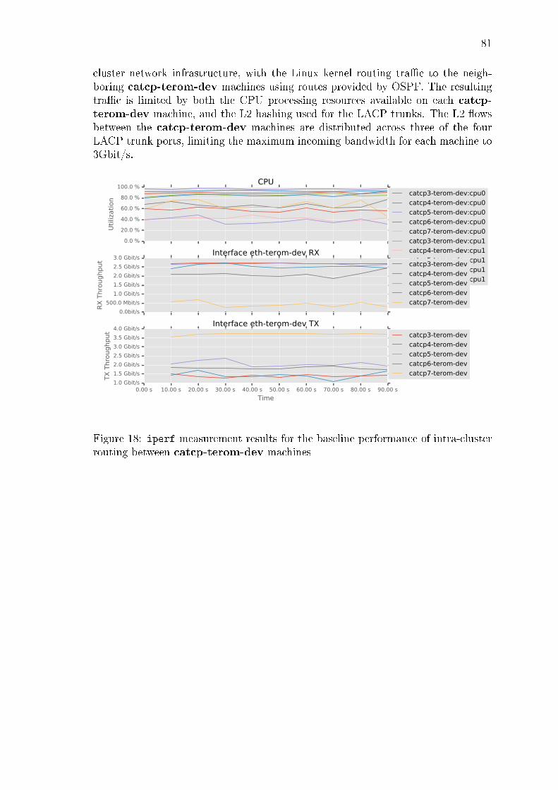
81
cluster network infrastructure, with the Linux kernel routing tra�c to the neigh-boring catcp-terom-dev machines using routes provided by OSPF. The resultingtra�c is limited by both the CPU processing resources available on each catcp-terom-dev machine, and the L2 hashing used for the LACP trunks. The L2 �owsbetween the catcp-terom-dev machines are distributed across three of the fourLACP trunk ports, limiting the maximum incoming bandwidth for each machine to3Gbit/s.
0.0 %
20.0 %
40.0 %
60.0 %
80.0 %
100.0 %
Uti
lizati
on
CPUcatcp3-terom-dev:cpu0
catcp4-terom-dev:cpu0
catcp5-terom-dev:cpu0
catcp6-terom-dev:cpu0
catcp7-terom-dev:cpu0
catcp3-terom-dev:cpu1
catcp4-terom-dev:cpu1
catcp5-terom-dev:cpu1
catcp6-terom-dev:cpu1
catcp7-terom-dev:cpu1
0.0bit/s
500.0 Mbit/s
1.0 Gbit/s
1.5 Gbit/s
2.0 Gbit/s
2.5 Gbit/s
3.0 Gbit/s
RX
Thro
ughput
Interface eth-terom-dev RXcatcp3-terom-dev
catcp4-terom-dev
catcp5-terom-dev
catcp6-terom-dev
catcp7-terom-dev
0.00 s 10.00 s 20.00 s 30.00 s 40.00 s 50.00 s 60.00 s 70.00 s 80.00 s 90.00 s
Time
1.0 Gbit/s
1.5 Gbit/s
2.0 Gbit/s
2.5 Gbit/s
3.0 Gbit/s
3.5 Gbit/s
4.0 Gbit/s
TX
Thro
ughput
Interface eth-terom-dev TXcatcp3-terom-dev
catcp4-terom-dev
catcp5-terom-dev
catcp6-terom-dev
catcp7-terom-dev
Figure 18: iperf measurement results for the baseline performance of intra-clusterrouting between catcp-terom-dev machines

82
Table 2: Measurements for intra-cluster iperf between catcp-terom-dev machines
Interface eth-terom-dev RX Min Max 95'th percentile
catcp3-terom-dev 2.7 Gbit/s 2.7 Gbit/s 2.7 Gbit/scatcp4-terom-dev 2.4 Gbit/s 2.7 Gbit/s 2.7 Gbit/scatcp5-terom-dev 2.6 Gbit/s 2.7 Gbit/s 2.7 Gbit/scatcp6-terom-dev 1.9 Gbit/s 2.5 Gbit/s 2.3 Gbit/scatcp7-terom-dev 270.6 Mbit/s 694.3 Mbit/s 645.2 Mbit/s
Total 270.6 Mbit/s 2.7 Gbit/s 11.1 Gbit/s
Interface eth-terom-dev TX Min Max 95'th percentile
catcp3-terom-dev 1.3 Gbit/s 1.5 Gbit/s 1.5 Gbit/scatcp4-terom-dev 1.1 Gbit/s 1.7 Gbit/s 1.7 Gbit/scatcp5-terom-dev 1.9 Gbit/s 2.4 Gbit/s 2.3 Gbit/scatcp6-terom-dev 1.8 Gbit/s 1.9 Gbit/s 1.9 Gbit/scatcp7-terom-dev 3.5 Gbit/s 3.7 Gbit/s 3.7 Gbit/s
Total 1.1 Gbit/s 3.7 Gbit/s 11.2 Gbit/s
Figure 18 shows the achieved iperf upload throughput and resulting CPU utiliza-tion for the iperf upload test, with each iperf client connecting directly to eachremote iperf server (iperf -c catcpX-terom-dev.iperf.docker.test.catcp -t
300). The results show a high level of CPU utilization for each catcp-terom-devmachine, handling both the iperf client and server processes, as well as routing ofboth upload tra�c and return TCP ACK packets. The di�erent machines achievevarying upload rates between 1.1 - 3.7 Gbit/s, for a total combined 95th percentilethroughput of approximately 11Gbit/s as shown in table 2.
The behaviour of the catcp7-terom-dev machine is an outlier, with the iperf
clients on the machine sending signi�cant more tra�c than on other machines, andthe iperf server receiving signi�cantly less tra�c than on other machines. Onepossible explanation for this behaviour is the use of a di�erent Linux kernel onthe catcp7-terom-dev machine (Linux 4.4) than on the other catcp-terom-devmachines (Linux 3.16). The newer Linux kernel may prioritze the iperf clientprocesses sending tra�c over the local iperf server process receiving tra�c.
The results show that packet routing across the internal network is more CPU-intensive than simply switching tra�c between local Docker containers, with a higherCPU utilization for a lower throughput. The results are also highly suspectible tothe e�ects of the L2 hashing algorithm used for LACP trunking, which determinethe maximum achieivable throughput in quantiles of the gigabit Ethernet links usedfor trunking.

83
6.3.3 Inter-cluster symmetric routing
To measure the baseline performance of the inter-cluster network, we run an in-stance of the iperf service on each of the catcp-terom-dev machines. For eachcatcp-docker machine, we run multiple iperf clients connecting to each remoteiperf server, using the catcpX-terom-dev.iperf.docker.test.catcp DNS nameprovided by SkyDNS to resolve the address of each remote iperf server. This re-sults in a total of N ∗M iperf clients, one for each pair of catcp-terom-dev andcatcp-docker machines.
The resulting tra�c between the catcp-docker and catcp-terom-dev machines isrouted by the catcp1-gw and catcp2-test-gw machines across the core network.For the symmetric routing scenario, the other catcp-gw and catcp-test-gw routersare disabled (con�gured with a higher OSPF cost). The resulting inter-cluster tra�cis limited to 1Gbit/s by the use of L2 hashing for the single L2 �ow between thetwo gateway machines, as all packets for the catcp2-test-gw machine are hashedto the same LACP trunk port on the CATCP2 machine.
0.0 %20.0 %40.0 %60.0 %80.0 %
100.0 %
Uti
lizati
on
CPUcatcp1-gw:cpu0
catcp2-test-gw:cpu0
catcp1-gw:cpu1
catcp2-test-gw:cpu1
0.0bit/s200.0 Mbit/s400.0 Mbit/s600.0 Mbit/s800.0 Mbit/s
1.0 Gbit/s
RX
Thro
ughput Interface eth-core RXcatcp1-test-gw
catcp2-test-gw
catcp5-test-gw
0.0bit/s200.0 Mbit/s400.0 Mbit/s600.0 Mbit/s800.0 Mbit/s
1.0 Gbit/s
TX
Thro
ughput Interface eth-core TX
catcp1-gw
catcp6-gw
10.00 s 25.00 s 40.00 s 55.00 s 70.00 s 85.00 s 100.00 s
Time
120.0 Mbit/s140.0 Mbit/s160.0 Mbit/s180.0 Mbit/s200.0 Mbit/s220.0 Mbit/s240.0 Mbit/s260.0 Mbit/s
RX
Thro
ughput Interface eth-terom-dev RX
catcp3-terom-dev
catcp4-terom-dev
catcp5-terom-dev
catcp6-terom-dev
catcp7-terom-dev
Figure 19: iperf measurement results for the baseline performance of inter-clustersymmetric routing
Figure 19 shows the achieved iperf upload throughput and resulting gateway ma-chine CPU utilization when using symmetric routing for packets between the twoDocker cluster networks, with each iperf client connecting directly to each remoteiperf server (iperf -c catcpX-terom-dev.iperf.docker.test.catcp -t 120). The

84
results show a low level of CPU utilization for the catcp1-gw and catcp2-test-gwmachines forwarding both the upload tra�c and return TCP ACK packets, achiev-ing a stable 1Gbit/s upload rate with somewhat unevenly distributed tra�c acrossthe server machines. Both catcp1-gw and catcp2-test-gw are routing approxi-mately 200k packets/s in each direction, for a total of approximately 400k packet/sper machine.
6.3.4 Inter-cluster multipath routing
To expand the capacity of the inter-cluser network, we con�gure two pairs of Gate-way machines with the same OSPF costs, providing multiple equal-cost paths usedfor L3 load balancing across the core network. Each of the catcp-terom-dev andcatcp-docker machines uses OSPF ECMP routing for L3 load-balancing of tra�cacross each pair of Gateway machines. The resulting inter-cluster tra�c uses a totalof four L2 �ows between the two pairs of Gateway machines on the core network,limiting the total attainable throughput to 2-4Gbit/s depending on the resultingdistribution of L2 �ow hashes. Tra�c from multiple di�erent machines is hashed tothe same LACP trunk interface on catcp1, causing the catcp1-test-gw machineto receive less tra�c than the catcp5-test-gw machine.
0.0 %20.0 %40.0 %60.0 %80.0 %
100.0 %
Uti
lizati
on
CPUcatcp1-test-gw:0
catcp1-test-gw:1
catcp5-test-gw:0
catcp5-test-gw:1
0.0bit/s200.0 Mbit/s400.0 Mbit/s600.0 Mbit/s800.0 Mbit/s
1.0 Gbit/s1.2 Gbit/s1.4 Gbit/s1.6 Gbit/s1.8 Gbit/s
RX
Thro
ughput Interface eth-core RX
catcp1-test-gw
catcp5-test-gw
0.0bit/s200.0 Mbit/s400.0 Mbit/s600.0 Mbit/s800.0 Mbit/s
1.0 Gbit/s1.2 Gbit/s1.4 Gbit/s1.6 Gbit/s
TX
Thro
ughput Interface eth-core TX
catcp1-gw
catcp6-gw
8.46 s
68.46 s
128.46 s
188.46 s
248.46 s
308.46 s
Time
0.0bit/s200.0 Mbit/s400.0 Mbit/s600.0 Mbit/s800.0 Mbit/s
1.0 Gbit/s
RX
Thro
ughput Interface eth-terom-dev RX
catcp3-terom-dev
catcp4-terom-dev
catcp5-terom-dev
catcp6-terom-dev
catcp7-terom-dev
Figure 20: iperf measurement results for the baseline performance of inter-clustermultipath routing
Figure 20 shows the achieved iperf upload throughput and resulting Gateway CPU

85
utilization for the iperf upload test when using ECMP routing between two pairsof gateway machines, with each iperf client connecting directly to the iperf serverDocker containers (iperf -c catcpX-terom-dev.iperf.docker.test.catcp -t
300). The results show a moderate level of CPU utilization for the catcp-test-gw machines forwarding both the upload tra�c and return TCP ACK packets,achieving a combined 2.5Gbit/s total upload rate with tra�c evenly distributedacross the server machines.
The L2 �ows in this scenario saturate LACP trunk interfaces on catcp1 (1 interface),catcp6 (1 interface) and catcp5 (2 interfaces). The lower eth-core RX throughputfor the catcp1-test-gw machine is presumably explained by upload tra�c fromcatcp-docker machines to the catcp1-gw machine colliding with upload tra�crouted by the catcp6-gw machine.
6.4 Comparing Implementation Performance
To compare the performance of a single Linux IPVS network-level load balancerwith the performance of a single HAProxy application-level load balancer, we usethe symmetric routing scenario shown in Section 6.3.3. One instance of the iperf
service is run on each of the catcp-terom-dev machines, using clusterf-docker
to provide a clusterf ServiceBackend for each service instance within etcd. Foreach catcp-docker machine, we run a single iperf client, connecting to the load-balanced iperf service using the 10.0.107.2 VIP announced by catcp2-test-gw.All of the iperf upload tra�c and returning TCP ACK packets are routed viathe same catcp2-test-gw machine. The catcp2-test-gw machine is con�guredto either run the clusterf or HAProxy load balancers, using the same clusterf
service con�guration provided by clusterf-docker for both load balancers. Thiscon�guration has the gateway machine as a single point of failure with no optionsfor failover.
6.4.1 The HAProxy application-level load balancer
The catcp2-test-gw machine is con�gured to run a combination of HAProxy andconfd to load balance incoming TCP connections for the iperf service across eachof the catcp-terom-dev iperf server containers.

86
0.0 %20.0 %40.0 %60.0 %80.0 %
100.0 %
Uti
lizati
on
CPUcatcp1-gw:cpu0
catcp2-test-gw:cpu0
catcp1-gw:cpu1
catcp2-test-gw:cpu1
0.0bit/s200.0 Mbit/s400.0 Mbit/s600.0 Mbit/s800.0 Mbit/s
1.0 Gbit/s
RX
Thro
ughput Interface eth-core RX
catcp1-test-gw
catcp2-test-gw
catcp5-test-gw
0.0bit/s200.0 Mbit/s400.0 Mbit/s600.0 Mbit/s800.0 Mbit/s
1.0 Gbit/s
TX
Thro
ughput Interface eth-core TX
catcp1-gw
catcp6-gw
10.00 s 25.00 s 40.00 s 55.00 s 70.00 s 85.00 s 100.00 s
Time
0.0bit/s50.0 Mbit/s
100.0 Mbit/s150.0 Mbit/s200.0 Mbit/s250.0 Mbit/s300.0 Mbit/s350.0 Mbit/s400.0 Mbit/s
RX
Thro
ughput Interface eth-terom-dev RX
catcp3-terom-dev
catcp4-terom-dev
catcp5-terom-dev
catcp6-terom-dev
catcp7-terom-dev
Figure 21: iperf measurement results for HAProxy load balancing with symmetricrouting
Figure 21 shows the achieved iperf upload throughput and resulting Gateway CPUutilization for the iperf upload test using the HAProxy load-balancer (iperf -c
10.0.107.2 -t 120). The results show a high level of CPU utilization for thecatcp2-test-gw machine using HAProxy to forward the TCP connections, achiev-ing a stable 1Gbit/s upload rate with tra�c evenly distributed across the iperf
servers. Both catcp1-gw and catcp2-test-gw are routing approximately 100kpackets/s in each direction, for a total of 200k packet/s for each machine.
This result shows that using the HAProxy application-level proxy for load-blanacinghas a signi�cant CPU overhead compared to the symmetric routing con�gurationwithout any load balancing in Section 6.3.3.
6.4.2 The IPVS network-level load balancer
The catcp2-test-gwmachine is con�gured to run the clusterf-ipvs control plane,using Linux IPVS to load balance packets for incoming TCP connections to theiperf service across each of the catcp-terom-dev iperf server containers.

87
0.0 %20.0 %40.0 %60.0 %80.0 %
100.0 %
Uti
lizati
on
CPUcatcp1-gw:cpu0
catcp2-test-gw:cpu0
catcp1-gw:cpu1
catcp2-test-gw:cpu1
0.0bit/s200.0 Mbit/s400.0 Mbit/s600.0 Mbit/s800.0 Mbit/s
1.0 Gbit/s
RX
Thro
ughput Interface eth-core RX
catcp1-test-gw
catcp2-test-gw
catcp5-test-gw
0.0bit/s200.0 Mbit/s400.0 Mbit/s600.0 Mbit/s800.0 Mbit/s
1.0 Gbit/s
TX
Thro
ughput Interface eth-core TX
catcp1-gw
catcp6-gw
10.00 s 25.00 s 40.00 s 55.00 s 70.00 s 85.00 s 100.00 s
Time
0.0bit/s50.0 Mbit/s
100.0 Mbit/s150.0 Mbit/s200.0 Mbit/s250.0 Mbit/s300.0 Mbit/s350.0 Mbit/s
RX
Thro
ughput Interface eth-terom-dev RX
catcp3-terom-dev
catcp4-terom-dev
catcp5-terom-dev
catcp6-terom-dev
catcp7-terom-dev
Figure 22: iperf measurement results for IPVS load balancing with symmetricrouting
Figure 22 shows the achieved iperf upload throughput and resulting GatewayCPU utilization for the iperf upload test using the IPVS load balancer (iperf-c 10.0.107.2 -t 120). The results show low CPU utilization for the catcp2-test-gw machine forwarding both the upload tra�c and return TCP ACK packets,achieving a stable 1Gbit/s upload rate with tra�c evenly distributed across theiperf servers. Both catcp1-gw and catcp2-test-gw are routing approximately100k packets/s in each direction, for a total of 200k packet/s for each machine.
This result shows that using the IPVS network-layer load-balancer for load balanc-ing has similar CPU overhead to the symmetric routing con�guration without anyload balancing in Section 6.3.3. However, the two scenarios di�er in the numberof iperf clients, with the use of fewer iperf clients resulting in a smaller packet-s/s rate for this experiment, and thus a lower level of CPU utilization for packetrouting. However, the number of iperf clients and resulting packets/s rate for thisexperiment is the same as in the equivalent HAProxy experiment in Section 6.4.1.
6.5 Scaling the clusterf Load Balancer
To evaluate the horizontal scaling capabilities of the IPVS load balancer, we use themultipath routing scenario described in Section 6.3.4. The catcp-terom-dev ma-chines are used to run 12 iperf server instances of the iperf service. Both catcp1-

88
test-gw and catcp5-test-gw machines are con�gured using the same OSPF costs,allowing tra�c in both directions to be distributed between both machines. Bothcatcp1-test-gw and catcp5-test-gw machines are con�gured to announce thesame 10.0.107.0 VIP with equal OSPF costs, causing tra�c for the 10.0.107.0
VIP to be distributed across both load balancers. This con�guration provides op-tions for testing failover, as tra�c for each VIP can be routed to either of thecatcp-test-gw machines.
6.5.1 ECMP routing for a single VIP
The ability to add more load balancers to scale the total load balancing capacityavailable for a service is demonstrated using two IPVS load balancers sharing asingle VIP with ECMP routing. The catcp-docker machines are used to run 8iperf client instances, connecting to the 10.0.107.0 VIP announced by both loadbalancer machines.
0.0 %20.0 %40.0 %60.0 %80.0 %
100.0 %
Uti
lizati
on
CPUcatcp1-test-gw:0
catcp1-test-gw:1
catcp5-test-gw:0
catcp5-test-gw:1
0.0bit/s200.0 Mbit/s400.0 Mbit/s600.0 Mbit/s800.0 Mbit/s
1.0 Gbit/s1.2 Gbit/s1.4 Gbit/s1.6 Gbit/s
RX
Thro
ughput Interface eth-core RX
catcp1-test-gw
catcp5-test-gw
0.0bit/s200.0 Mbit/s400.0 Mbit/s600.0 Mbit/s800.0 Mbit/s
1.0 Gbit/s1.2 Gbit/s1.4 Gbit/s1.6 Gbit/s
TX
Thro
ughput Interface eth-core TX
catcp1-gw
catcp6-gw
12.85 s
72.85 s
132.85 s
192.85 s
252.85 s
312.85 s
Time
0.0bit/s100.0 Mbit/s200.0 Mbit/s300.0 Mbit/s400.0 Mbit/s500.0 Mbit/s600.0 Mbit/s700.0 Mbit/s
RX
Thro
ughput Interface eth-terom-dev RX
catcp3-terom-dev
catcp4-terom-dev
catcp5-terom-dev
catcp6-terom-dev
catcp7-terom-dev
Figure 23: iperf measurement results for IPVS load balancing with EMCP routingfor a single VIP
Figure 23 shows achieved network upload throughput and resulting gateway CPUutilization for the iperf upload test using the IPVS load-balancer, connecting tothe ECMP VIP address (iperf -c 10.0.107.0 -P 2 -t 300). The results showa moderate level of CPU utilization for the catcp-test-gw machines forwardingboth the upload tra�c and return TCP ACK packets, achieving an approximately

89
2.5Gbit/s total upload rate with tra�c moderately distributed across the servermachines.
This result demonstrates that the clusterf design is capable of horizontal scalingof tra�c for a single VIP across multiple IPVS network-level load balancers usingECMP routing. Using ECMP routing to distribute tra�c for a single VIP acrossmultiple IPVS load balancers providing more throughput (2.5Gbit/s) than whenusing a single IPVS load balancer (1Gbit/s). The 2.5x increase in performanceis an artifact of the use of L2 load balancing for the underlying physical networkinfrastructure, resulting from the use of 4 distinct L2 �ows between two pairs ofrouters compared to the use of a single L2 �ow between a single pair of routers. Theimbalance of throughput levels between the two gateways is a result of the L2 �owhashing collisions discussed in Section 6.3.4.
6.5.2 Connection failover for a single VIP with ECMP routing
To test the use of IPVS connection synchronization for fault tolerance, we use asingle iperf client on a randomly selected catcp-dockermachine, connecting to the10.0.107.0 VIP announced by both IPVS load balancer machines. The catcp1-test-gw and catcp5-test-gw machines use IPVS connection synchronization toshare the load-balanced connection states.
0.0bit/s
200.0 Mbit/s
400.0 Mbit/s
600.0 Mbit/s
800.0 Mbit/s
1.0 Gbit/s
RX
Thro
ughput
Interface eth-core RXcatcp1-test-gw
catcp5-test-gw
0.0bit/s
200.0 Mbit/s
400.0 Mbit/s
600.0 Mbit/s
800.0 Mbit/s
1.0 Gbit/s
TX
Thro
ughput
Interface eth-core TXcatcp1-gw
catcp6-gw
28.46 s
88.46 s
148.46 s
208.46 s
268.46 s
328.46 s
Time
0.0bit/s
200.0 Mbit/s
400.0 Mbit/s
600.0 Mbit/s
800.0 Mbit/s
1.0 Gbit/s
RX
Thro
ughput
Interface eth-terom-dev RXcatcp3-terom-dev
catcp4-terom-dev
catcp5-terom-dev
catcp6-terom-dev
catcp7-terom-dev
Figure 24: iperf measurement results for IPVS failover with ECMP routing for asingle VIP

90
In Figure 24, a single iperf -c 10.0.107.0 -t 120 client is run on the catcp-docker nodes, which establishes a single TCP connection to the VIP at t = 121s,and transmits data for a total of 120 seconds. The packets for this connectionare initially routed using ECMP to the catcp5-test-gw machine, as shown by the1Gbit/s of RX throughput on the catcp5-test-gw machine's eth-core interface.At t = 180s, the catcp5-test-gw machine fails, withrawing the OSPF route for theVIP. The catcp1-gw machine updates its routing table to forward all packets forthe VIP to catcp1-test-gw. Using the IPVS connection state synchronized fromthe failed load-balancer node, the IPVS load balancer on catcp1-test-gw is able toresume forwarding the packets for the existing iperf connection. The iperf clientsuccesfully completes its test at t = 260s after a brief hiccup, despite the failure ofthe initial load balancer used for the connection and resulting ECMP rerouting ofpackets to a di�erent load balancer.
This result demonstrates that the clusterf design provides fault tolerance for mul-tiple IPVS load balancers using connection synchronization and ECMP routing fora single VIP. The use of IPVS masq for NAT forwarding within the catcp6-terom-dev Docker machine is not disrupted by the migration of incoming tra�c acrossdi�erent Gateway machines.
6.6 Analysis
The clusterf load balancer behaves as designed in each of the load balancingscenarios tested. The clusterf load balancer preserves the original network sourceaddress of the client, while allowing the use of varying port numbers for the listeningserver. The clusterf load balancer is capable of distributing incoming tra�c acrossmultiple Docker container backends, allowing the horizontal scaling of Docker ma-chines and service containers. The clusterf load balancer is capable of distributingincoming tra�c across multiple Gateway machines, allowing the horizontal scalingof Gateway machines and VIPs. The failure of a Gateway machine does not causethe failure of active connections when using IPVS connection state synchronization.
Using IPVS for load balancing involves minimal overhead compared to the equiva-lent routing of packets within the Linux kernel. Using HAProxy for load balancinginvolves signi�cnat processing overhead compared to the equivalent routing of pack-ets within the Linux kernel. The quantitative analysis of any pair of network-leveland application-level load balancer implemenations cannot itself be used to drawany conclusions about the performance of application-level and network-level loadbalancers in general. It is entirely possible for a well implemented application-levelload balancer to have better performance than a poorly implemented network-levelload balancer, and vice-versa.
The study of existing network-level load balancer implementations in Section 3.4shows that network-level load balancer implementations are capable of achiving

91
very high levels of performance. A single Maglev load balancer with 8 CPU coresis capable of achiving packet processing rates beyond the 12 M packets/s line ratelimit of 10-gigabit Ethernet by implementing a userspace networking stack, wherethe Linux kernel network implementation was only able to handle less than 4 Mpackets/s in the same con�guration [7]. Any application-level load balancer imple-mentation will be limited by the performance of the underlying Linux kernel networkimplementation.

92
7 Conclusions
A container platform based on Docker can be used for the development and deploy-ment of horizontally scalable services on both local machines and within cloud serverinfrastructures. Such a container platform will include various components, includ-ing a container engine, an orchestration system, an internal network infrastructure,a dynamic service discovery mechanism, and a load balancer. The load balancerplays a critical role in the scalability of any cloud service, and thus the scalabilityof the load balancer itself must also be considered when designing such a containerplatform. A container platform supporting dynamic scaling of services must alsohave a dynamic load balancer control plane capable of automatically distributingincoming tra�c as service instances are added and removed.
Based on a study of the background networking and load balancing theory in Sec-tions 2.3 and 2.5 and existing implementations of load balancers in Section 3.4, Icreate a design for a scalable network-level load balancer. The clusterf design usesthe Linux IPVS network-level load balancer implementation to provide a scalableload balancer data plane, using a two-level load balancing scheme with both DSRand NAT forwarding for both scalability and compatibility with existing Docker con-tainers and applications. I implement the clusterf control plane for the automaticload balancing of Docker services within a cluster. The design and implementationof the clusterf load balancer is evaluated within a testbed network infrastructureusing standard Ethernet networking with ECMP routing capabilities for network-layer load balancing.
The results in Chapter 6 show that the clusterf load balancer provides excellentperformance and reliability for load balancing horizontally scaled services withina container platform as studied in Chapter 3. The results in Section 6.4 showthat the Linux IPVS network-level load balancer implementation provides betterperformance than the HAProxy application-level load balancer implementation. Theresults in Section 6.5 show that the clusterf design is capable of scaling in termsof both performance and reliability using standard network-layer ECMP routing.However, the current implementation of the clusterf load balancer assumes theuse of standard Ethernet networking allowing the use of asymmetric routing forDirect Server Return (DSR). Extending the clusterf design for load balancingwithin arbitrary cloud network infrastructures that restrict the use of asymmetricrouting is the subject of further study.
IETF BCP 38 [32] requires source address �ltering within networks to prevent theabuse of source address spoo�ng for Denial of Service (DoS) attacks. Dependingon the exact implementation of such Reverse Path Filtering (RPF), complying withBCP 38 for ingress �ltering of spoofed source addresses may preclude the use ofasymmetric routing for DSR load balancing within a network. The author can onlyspeculate as to the various implementations of RPF within cloud network infras-tructures, but the generally valid assumption for a container platform designed for

93
deployment across arbitrary network infrastructures is that each host only has asingle external network address. Resolving this design con�ict is the subject offurther research, involving either extending the clusterf design to use multipleseparate VIPs with DNS load balancing, or exploring the possibilities for the use ofasymmetric routing and DSR within various cloud infrastructure platforms.
In the meantime, network-level load balancer implementations are more likely tobe found within speci�c cloud infrastructure platforms. The providers of physicalcloud platforms have both more control over the speci�c network infrastructureimplementation and con�guration, allowing the use of network-level techniques suchas ECMP and DSR for load balancing, and operate at a su�ciently large scale forthe scalability di�erences between application-level and network-level load balancersto become apparent. Examples of such cloud provider speci�c network-level loadbalancer implemenations include the Amazon Web Services (AWS) Elastic LoadBalancer (ELB), the Microsoft Azure Ananta [8] load balancer, and the GoogleCompute Engine (GCE) Maglev [7] load balancers.
As a corollary, portable container platforms designed for deployment across dif-ferent network infrastructure environments are more likely to use application-levelload balancing methods. The use of application-level load balancing for proxyingtransport-layer connections allows the use of symmetrically routed connections be-tween and within arbitrary networks. However, scaling such an application-levelload balancer either requires the use of DNS within the Internet for load balanc-ing client tra�c across multiple VIPs, or the use of a scalable network-level loadbalancer provided by the cloud infrastructure platform. Designing a load balancercontrol plane for a container platform capable of integrating with either global DNSload balancing or various platform-speci�c load balancer infrastructures to avoidcloud vendor lock-in [10] is also a subject for future research.
Detailed study of the recent Docker 1.12 service routing mesh using the samenetwork-level Linux IPVS load balancer implementation as used in clusterf is alsothe subject of future research. The author speculates that the Docker 1.12 serviceload balancer design is based on the use of Full NAT for forwarding, thus resemblingmore of a high-performance application-level load balancer implementation than anetwork-level load balancer design. Based on the background networking theoryand study, the author hypothesies that the Docker 1.12 implementation of network-level load balancing is unable to support network source address transparency orconnection failover between machines. Without the use of external load balancingrouting con�gured to route tra�c to speci�c Docker Swarm nodes, the loss of anyDocker Swarm node acting as a service load balancer may lead to the failure of activeconnections routed to the remaining healthy nodes. Testing this hypothesis is out-side the scope of this thesis, and the author disclaims the possibility for theoreticalmisunderstandings and any future extensions of the Docker Swarm implementationthat may negate this hypothesis.

94
The clusterf load balancer as currently implemented is thus generally unsuitablefor use within a container platform intended to be portable across di�erent network-ing environments. With further research of the limitations and proposals exploredthroughout Chapter 4, the author believes that the use of a truly scalable network-level load balancer for horizontally scalable Docker services deployed across multiplecloud platforms may be possible. Until then, users of container platforms will likelybe using application-level load balancer designs that are capable of providing sat-isfactory levels of performance and reliability as well as additional �exibility forapplication-layer load balancing.
After all, there are numerous other reasons for client connections to fail, and as-suming the existence of client support for reconnecting on connection loss, do wereally need to pay the price for the complexity of a network-level load balancer de-sign including complete support for connection failover on load balancer failures?Horizontal scalability is about the design of abstract distributed computing layerswhile navigating the mine�eld of inenvitable practical implementation issues. Theanswer to the ultimate question of load balancers, the implementation of dynamicservice discovery and application container platforms may lie in the role of VIPs inthe implementation of dynamic service discovery for client applications, a topic notfully explored in this thesis.

REFERENCES 95
References
[1] Peter Mell and Tim Grance. �The NIST de�nition of cloud computing�. In:(2011).
[2] Abhishek Verma et al. �Large-scale cluster management at Google with Borg�.In: Proceedings of the Tenth European Conference on Computer Systems. ACM.2015, p. 18.
[3] David Lo et al. �Heracles: improving resource e�ciency at scale�. In: ACMSIGARCH Computer Architecture News. Vol. 43. 3. ACM. 2015, pp. 450�462.
[4] Brendan Burns et al. �Borg, Omega, and Kubernetes�. In: ACM Queue 14.1(2016), p. 10.
[5] Evolution of the Modern Software Supply Chain. Tech. rep. Docker, Inc, Apr.2016.
[6] ClearPath Strategies. Hope Versus Reality: Containers In 2016. Tech. rep.Cloud Foundry Foundation, June 2016.
[7] Daniel E Eisenbud et al. �Maglev: A Fast and Reliable Software NetworkLoad Balancer�. In: 13th USENIX Symposium on Networked Systems Designand Implementation (NSDI 16). 2016, pp. 523�535.
[8] Parveen Patel et al. �Ananta: cloud scale load balancing�. In: ACM SIGCOMMComputer Communication Review. Vol. 43. 4. ACM. 2013, pp. 207�218.
[9] Jürgen Cito et al. �The making of cloud applications: An empirical study onsoftware development for the cloud�. In: Proceedings of the 2015 10th JointMeeting on Foundations of Software Engineering. ACM. 2015, pp. 393�403.
[10] Nane Kratzke. �A lightweight virtualization cluster reference architecture de-rived from open source paas platforms�. In: Open J. Mob. Comput. CloudComput 1 (2014), pp. 17�30.
[11] Dirk Merkel. �Docker: lightweight linux containers for consistent developmentand deployment�. In: Linux Journal 2014.239 (2014), p. 2.
[12] cgroups(7) Linux Programmer's Manual. 4.06.
[13] namespaces(7) Linux Programmer's Manual. 4.06.
[14] Benjamin Hindman et al. �Mesos: A Platform for Fine-Grained Resource Shar-ing in the Data Center.� In: NSDI. Vol. 11. 2011, pp. 22�22.
[15] Andrew S Tanenbaum. �Computer Networks 4th Edition�. In: (2003).
[16] Victor Marmol, Rohit Jnagal, and Tim Hockin. �Networking in Containersand Container Clusters�. In: Proceedings of netdev 0.1 (Feb. 2015).
[17] Joris Claassen, Ralph Koning, and Paola Grosso. �Linux containers network-ing: Performance and scalability of kernel modules�. In: NOMS 2016-2016IEEE/IFIP Network Operations and Management Symposium. IEEE. 2016,pp. 713�717.

REFERENCES 96
[18] Y. Rekhter et al. Address Allocation for Private Internets. RFC 1918 (BestCurrent Practice). Updated by RFC 6761. Internet Engineering Task Force,Feb. 1996. url: http://www.ietf.org/rfc/rfc1918.txt.
[19] P. Srisuresh and M. Holdrege. IP Network Address Translator (NAT) Termi-nology and Considerations. RFC 2663 (Informational). Internet EngineeringTask Force, Aug. 1999. url: http://www.ietf.org/rfc/rfc2663.txt.
[20] M. Mahalingam et al. Virtual eXtensible Local Area Network (VXLAN): AFramework for Overlaying Virtualized Layer 2 Networks over Layer 3 Net-works. RFC 7348 (Informational). Internet Engineering Task Force, Aug. 2014.url: http://www.ietf.org/rfc/rfc7348.txt.
[21] T. Narten, G. Huston, and L. Roberts. IPv6 Address Assignment to End Sites.RFC 6177 (Best Current Practice). Internet Engineering Task Force, Mar.2011. url: http://www.ietf.org/rfc/rfc6177.txt.
[22] D. Thaler and C. Hopps. Multipath Issues in Unicast and Multicast Next-HopSelection. RFC 2991 (Informational). Internet Engineering Task Force, Nov.2000. url: http://www.ietf.org/rfc/rfc2991.txt.
[23] M. Byerly, M. Hite, and J. Jaeggli. Close Encounters of the ICMP Type 2Kind (Near Misses with ICMPv6 Packet Too Big (PTB)). RFC 7690 (Infor-mational). Internet Engineering Task Force, Jan. 2016. url: http://www.ietf.org/rfc/rfc7690.txt.
[24] R. Fielding et al. Hypertext Transfer Protocol � HTTP/1.1. RFC 2616 (DraftStandard). Obsoleted by RFCs 7230, 7231, 7232, 7233, 7234, 7235, updatedby RFCs 2817, 5785, 6266, 6585. Internet Engineering Task Force, June 1999.url: http://www.ietf.org/rfc/rfc2616.txt.
[25] Fangfei Chen, Ramesh K Sitaraman, and Marcelo Torres. �End-user mapping:Next generation request routing for content delivery�. In: ACM SIGCOMMComputer Communication Review. Vol. 45. 4. ACM. 2015, pp. 167�181.
[26] Don Mills. Docker Multi-Host Networking: Overlays to the Rescue. Tech. rep.SingleStone. url: https://www.singlestoneconsulting.com/~/media/files/whitepapers/dockernetworking2.pdf.
[27] Diego Ongaro and John Ousterhout. �In search of an understandable consensusalgorithm�. In: 2014 USENIX Annual Technical Conference (USENIX ATC14). 2014, pp. 305�319.
[28] Nane Kratzke. �About microservices, containers and their underestimated im-pact on network performance�. In: Proceedings of CLOUD COMPUTING 2015(2015).
[29] Nane Kratzke and Peter-Christian Quint. �How to Operate Container Clustersmore E�ciently?� In: International Journal On Advances in Networks andServices 8.3&4 (2015), pp. 203�214.

REFERENCES 97
[30] Alex Gartrell. [PATCH ipvs 0/7] Support v6 real servers in v4 pools and viceversa. July 2014. url: http://archive.linuxvirtualserver.org/html/lvs-devel/2014-07/msg00047.html.
[31] Brendan Gregg. �Thinking methodically about performance�. In: Communi-cations of the ACM 56.2 (2013), pp. 45�51.
[32] P. Ferguson and D. Senie. Network Ingress Filtering: Defeating Denial of Ser-vice Attacks which employ IP Source Address Spoo�ng. RFC 2827 (Best Cur-rent Practice). Updated by RFC 3704. Internet Engineering Task Force, May2000. url: http://www.ietf.org/rfc/rfc2827.txt.