
DESIGN AND IMPLEMENTATION OF REMOTE …...control system (i.e., mobile phone based control...
70
DESIGN AND IMPLEMENTATION OF REMOTE MULTIPLE LOADS CONTROL SYSTEM USING MOBILE PHONE Debasish Das Department of Electrical & Electronic Engineering Dhaka University of Engineering & Technology, Gazipur-1700,Bangladesh. June, 2015
Transcript of DESIGN AND IMPLEMENTATION OF REMOTE …...control system (i.e., mobile phone based control...

DESIGN AND IMPLEMENTATION OF REMOTE
MULTIPLE LOADS CONTROL SYSTEM
USING MOBILE PHONE
Debasish Das
Department of Electrical & Electronic Engineering
Dhaka University of Engineering & Technology,
Gazipur-1700,Bangladesh.
June, 2015

ii
DESIGN AND IMPLEMENTATION OF REMOTE MULTIPLE LOADS
CONTROL SYSTEM USING MOBILE PHONE
A Project Report submitted to the Department of Electrical and Electronic Engineering in
partial fulfillment of the requirements for the degree
Of
MASTER OF ENGINEERING IN ELECTRICAL AND ELECTRONIC ENGINEERING
By
Debasish Das
Student No: 052201P
Under the supervision of
Dr. Md. Monirul Kabir
Assistant Professor
Department of Electrical and Electronic Engineering
Dhaka University of Engineering and Technology
Department of Electrical and Electronic Engineering.
DHAKA UNIVERSITY OF ENGINEERING AND TECHNOLOGY,
GAZIPUR – 1700, BANGLADESH

iii
The Project Reportentitled “DESIGN AND IMPLEMENTATION OF REMOTE
MULTIPLELOADS CONTROL SYSTEM USING MOBILE PHONE” submitted by Debasish
Das, Roll no: 052201P, Session: 2005-2006 has been accepted as satisfactory in partial
fulfillment of the requirement for the degree of MASTER OF ENGINEERING IN
ELECTRICAL AND ELECTRONIC ENGINEERING on June 10, 2015.
BOARD OF EXAMINERS
1
.
Professor Dr. Md.SaifuddinFaruk
Head
Department of Electrical and Electronic Engineering
Dhaka University of Engineering and Technology(DUET)
Chairman
2
.
Dr. Md. Bashir Uddin
Professor
Department of Electrical and Electronic Engineering
Dhaka University of Engineering and Technology(DUET)
Member
3
.
Dr. Md. Raju Ahmed
Associate Professor
Department of Electrical and Electronic Engineering
Dhaka University of Engineering and Technology(DUET)
Dr. Md.MonirulKabir
Assistant Professor
Department of Electrical and electronic Engineering
Dhaka University of Engineering and Technology(DUET)
Member
Member
(Supervisor)
4
.
Professor Dr. Md. ShahidUllah
Head
Department of Electrical and electronic Engineering
Islamic University of Technology (IUT), Gazipur
Member
(External)

iv
CANDIDATE’S DECLARATION
I hereby declare that this project or any part of it has not been submitted elsewhere for the
award of any degree or diploma or publication.
_________________________________________
Debasish Das
Student ID: 052201P

v
ACKNOWLEDGEMENT
I would like to express my gratitude and profound indebtedness to my supervisor Dr. Md.
Mnirul Kabir, Assistant Professor, Department of Electrical and Electronic Engineering of
Dhaka University of Engineering and Technology (DUET), Gazipur, Bangladesh for his
guidance, inspiration and helpful support throughout my project work without which the work
could not be completed.
I would like to express my gratitude and specially thanks to Dr. Anwarul Abedin, Professor,
Dept. of EEE, DUET, for his cordial help and valuable suggestions. I shall ever grateful to
him because of his random support to completion this project work. I would like to thanks
librarian of DUET to use library.

vi
ABSTRACT
In this project, a mobile phone based control system (MPCS) has been designed and
implemented to automatically communicate with the multiple electrical remote loads. The
proposed MPCS uses a microcontroller that is mainly connected with Double Tone Multiple
Frequency circuit, Global System for Mobile communication (GSM) modem, and multiple
electrical loads. The prime role of MPCS is to control the remote loads in respect of ON/OFF
switching using the mobile phone-based interface (MPI). To control the remote loads, the user
should send an authentication code through DTMF circuit along with the desired
function/action via GSM. After completed the proper authentication, user using MPI transmits
the commands to a microcontroller that performs the desired function/action. Furthermore, as
a feed-back information, MPCS provides the current status of all of the remote loads via short
messaging system (SMS) by the assistance of Tri-band Modem which is connected with
microcontroller as well as the user’s MPI through GSM. Additionally, the similar information
can also be provided through LCD display system. In order to evaluate the performance of
MPCS, a prototype module has been implemented, where four electrical lamps are considered
as the electrical loads. Experimentally, it was found that MPCS can effectively control the
remote electrical loads as well as provide the current status accurately using SMS.

vii
Contents
Board of Examiners iii
Declaration iv
Acknowledgement v
Abstract vi
List of Figures ix
List of Tables x
Nomenclature xi
Chapter 1 Introduction
1.1 Introduction 1
1.2 Motivation 3
1.3 Objective of the work 4
1.4 Significance of MPCS 4
1.5 Advantages of MPCS 5
1.6 Organizations
Chapter 2 Mobile Phone based Control System-MPCS
2.1 Proposed System-MPCS 6
2.1.1 Method used in MPCS 11
2.1.1.1UART method 11
2.1.1.2 AT command 12
2.2 List of components 13
2.3 Description of the components 14

viii
2.3.1 DTMF circuit 14
2.3.2 PIC16F877A microcontroller 14
2.3.3 Crystal oscillator 17
2.3.4 Electrical relay 17
2.3.5 SIM300CZ tri-band modem 19
2.3.6 LCD Display (16x2) 21
2.3.7 ULN2003 driver 23
2.4 Description of the software 24
2.4.1 MikroC Pro for PIC 24
2.4.2 Proteus 7.1 25
Chapter 3 Software used in MPCS
3.1 Description of Proteus 27
3.1.1 Overview of Proteus design suite 28
3.1.2 Circuit construction and assembly 28
3.1.3 PIC16F877A parameter setting 29
3.1.4 Simulation 29
3.2 Proteus layout of MPCS 31
3.3 MikroC programming tools 31
3.3.1 Creating new project 32
3.3.2 Coding template 32
3.4 AT command 36
3.4.1 Types of AT command 37
3.5 Pseudo code of MPCS 38
3.6 Program coding 40
Chapter 4 Experimental studies

ix
4.1 Experimental studies 48
4.1.1 Implementation and observation of DTMF circuit 48
4.1.2 Controlling and displaying loads using mobile phone 49
4.1.3 Final implementation of MPCS 53
4.1.4 Observation of current load status 54
Chapter 5 Conclusion
5.1 Conclusion 55
5.2 Recommendation for future work 56
References 57

x
LIST OF FIGURES
Fig.2.1: Block Diagram of MPCS 8
Fig.2.2: Flowchart of MPCS 9
Fig.2.3: Complete DTMF input and output diagram 11
Fig.2.4 Pin diagram of PIC16F877A microcontroller 15
Fig.2.5: Crystal oscillator 17
Fig.2.6: Electrical relay 18
Fig.2.7: LCD display 21
Fig.2.8: LCD display interfacing with PIC16F877A 22
Fig.2.9: ULN2003 driver 23
Fig.3.1: Overview of Proteus software 29
Fig.3.2: PIC parameter setting on Proteus 30
Fig.3.3: MPCS shown in Proteus 31
Fig.3.4: New wizard MikroC Pro for PIC microcontroller 32
Fig.3.5: Createa new project in Mikroc Pro for PIC 33
Fig. 3.6: Creating a new project wizard in MikroC Pro for PIC on process 34
Fig.3.7: Defining a file name 34
Fig.3.8: Select location to store hex file 35
Fig.3.9: Final step of a new project wizard 35
Fig: 3.10: Coding of MPCS and built in condition 37
Fig: 3.11: Classifications of AT commands 37
Fig.4.1: Implementation and observation of DTMF circuit 49
Fig.4.2: Controlling and displaying loads using mobile phone 50
Fig.4.3: Final Implementation of MPCS 51
Fig.4.4: Observation of current load status 52

xi
LIST OF TABLES
Table 2.1 A recognized truth table of DTMF circuit. 10
Table2.2 Pin description of PIC16F877A16 16
Table 2.3 Pin-diagram of LCD display 22
Table 4.1 DTMF test datasheet 50
Table 4.2 Results of MPCS 53

xii
Nomenclature
DTMF Dual Tone Multi Frequency
ROM Read Only Memory
RAM Random Access Memory
CPU Central Processing Unit
EEPROM Electrically Erasable Programmable ROM
pF Peko Farad
μF Micro Farad
VSS Ground
SSP Synchronous Serial port
L Logic Low
H Logic High
Z High Impedance
X Don’t Cary
OSCI Oscillator Input
ICSP In Circuit Serial Port
RS Register Select Signal
LD Loop Disconnect
C Coulomb
F Farad
VDD DC Power

1
Chapter 1
Introduction
This chapter describes about the introductory concept of mobile phone based control system,
its motivation, purposes of this work, and so on.
1.1 Introduction
The accessing and popularity of mobile technology is increasing day by day throughout the
whole world. Although the mobile phone mostly uses for voice conversations, it can be
served in different areas, such as, mobile banking, money transfer, home security, fire hazard
security, load control, and so on. In this regard, controlling the remote electrical loads is also
very much promising area.
At the early stages, some efforts have been done to control the home and office appliances.
In these works, they try to introduce about the controlling system using the telephone
networks involving stand-alone telephone set. Though their efforts are appreciated, users
will be deprived from the facility of mobile network. To facilitate such things, nowadays,
research has been going on the mobile technology in the developed countries as well as
Bangladesh also. In 2009, EEE department of DUET initiated first [1][3] to implement a
project, where a single electrical load can be ON/OFF using ringing signal of a mobile
phone. The attempt is nice but affected by several problems, such as, identifying the ringing
signal will be difficult, while ranging, variety and volume of the signal are changed. In order
to overcome the above-mentioned problems, the next attempt was done in 2010 [2]. In [2],
T. Begum implemented an improved automation system that can operate home usable
electrical loads using short messaging system (SMS) from global system for mobile (GSM)
oriented mobile phone. Although this system is effective than the previous one, suffered by
some problems: (i) handling the system using SMS that is more difficult for inexpert persons

Chapter1: Introduction
2
to operate, (ii) no security option is maintained. That is to say, an unauthorized person can
easily run any load from somewhere.
In the same time, furthermore, C. K. Das [3] proposes two theoretical models for mobile
phone-based electrical loads but not implemented yet. The scope of their proposals is out of
displaying the current load status through LCD as well as SMS.A recent work presented in,
where controlling and getting the status of loads by sending the message through the GSM
network.
In regard to overcome the above problems of the models [1-3], we are interested to develop a
control system (i.e., mobile phone based control system-MPCS) that may control the
multiple electrical loads including the home appliances as well as the industrial heavy loads
from a remote distances using any operated mobile phone. The key aspects of this project are
that, (a) MPCS will operate as well as control a number of remote electrical loads more than
10 in numbers easily, (b) loads might be accessed from longer distance even from out of
Bangladesh, (c) easy handling for the inexpert persons because of the use of mobile phone
interface only, instead of SMS, (d) current status of the remote electrical loads could be seen
easily any time by SMS, and (e) a unique LCD displays show the current load status locally.
Finally, the implementation of this project uses the main device DTMF (Double Tone
Multiple Frequency) decoder, this project works covers and fills up the drawbacks of
previous works.
The aim of the proposed system, MPCS is to develop a cost effective solution that will
provide controlling of home/office appliances remotely and enable home security against
intrusion in the absence of homeowner. The system provides availability due to development
of a low cost system. In this regard, MPCS requires a reasonable cost that uses two mobiles
providing remote access to the home appliances with allowing proper homesecurity. Though
devices connected as home, office appliances consume electrical power; these devices
should be controlled as well as turn ON/OFF if required. Most of the time as it was done
manually, now it is a necessity to control devices more effectively and efficiently at anytime
from anywhere. In this system, our attempt is to develop a mobile phone-based home/office
appliance controller that differs from. This system is designed for controlling arbitrary
devices that includes two mobile set(i.e., one is user mobile, another is remote mobile)

Chapter1: Introduction
3
connected through GSM mobile network, among which only the remote mobile is made of
the hardware connection with DTMF circuit and Microcontroller device. Specifically, “user
mobile” and “remote mobile” called as transmitter and receiver, respectively. In operation,
when the user makes a call to the remote mobile, then it receives the call automatically.
Then, the call is answered when the user enters a two/three digit password to access the
system for controlling the devices. As the caller press the specific password, it results in
turning ON/OFF the specific device. The switching of the specific device is performed by
the specific relay. In this system MPCS, security is preserved because of the dedicated user’s
passwords, which is known by the selected persons only. In addition, MCPS contains a Tri-
band Modem that has been connected with microcontroller physically as well as the user’s
modem through GSM in order to provide the current status of all of the remote loads via
SMS. The similar information can also be provided through LCD display system in MCPS.
1.2 Motivation
In Bangladesh, right now, the common practice is to operate the home and office appliances
manually. It is known that, the manual usage always requires the additional energy because
when the house/office owner is not available for a time, the existing electrical loads will be
operated unnecessarily. In this regard, mobile phone-based operation is much better than
manual practices. This kind of usage of mobile phone in our country is very rare. That’s
why, to operate the home and office appliances using mobile phone in Bangladesh, we are
interested to design and implement a project “Mobile Phone based Control System”, called
as MPCS that may control the various electrical loads efficiently. The proposed work is
formulated by two main techniques: (i) DTMF-based receiving circuit for the mobile phone
signals, and (ii) Microcontroller-based load control circuit.
1.3 Objectives of the work
The project MPCS is highlighted on basis of the following objectives:
i) To design and implement a control system by which home and office appliances
can be operated using mobile phone from the remote places.
ii) To simulate the circuit using Proteus software.
iii) To implement the circuit practically and verify the results.

Chapter1: Introduction
4
1.4 Significance of MPCS
The significant aspects of MPCS, which are mentioned below:
First, it allows any kind of GSM-based mobile phone networks available in Bangladesh in
order to communicate with the remote loads automatically.
Second, no expert human is required at the remote places to be made contact with the sender
end.
Third, anyone can get the current status about the remote loads individually whether it being
ON/OFF mode from the sender end. Thus, using the proper handling of offices or household
electrical appliances, where people often used to forget to switch off, energy saving can be
possible.
Fourth, further extension for the number of remote electrical loads can be possible in MPCS
any time. It can be noted that, our system MPCS has a very good future for our country’s
respect whether it could be established commercially at the industrial areas. Thus, our
industrial management will be more dynamic as well as the production cost will be reduced.
1.5 Advantages of MPCS
According to our view, the advantages of MPCS are stated below:
Controlling electrical devices wirelessly.
Quick response is achieved.
Very Easy to making the circuit and controlling multiple loads.
Design is efficient and low cost.
Can use any branded any model handset.
Can be used any GSM operator supported SIM card.
Energy savings.
This system can be used in industrial application.
This system can be employed in houses or offices, where people often forget to
switch off electrical appliances.
We can control appliances from any place round the globe.
Operator get feedback SMS including all load status from circuit.

Chapter1: Introduction
5
1.6 Organizations
This project report is organized by five chapters that are mentioned as follows:
Chapter 1 is the introductory chapter which gives an overall idea of the project, discussion
regarding previous works, objectives of my project work, significance of the Mobile Phone
based Control System-MPCS.
Chapter 2 briefs about Mobile Phone based Control System (MPCS), its block diagram,
step by step working procedure with flowchart and advantages of MPCS.
Chapter 3 describes highly about the software part of MPCS that has been used in its
working processes.
Chapter 4 presents the detailed experimental studies of MPCS including the observation of
current load status.
Chapter 5 finally concludes the discussion of MPCS with some future directions.

Chapter 2: Mobile Phone based Control System-MPCS
6
Chapter 2
Mobile Phone based Control System-MPCS
This chapter presents the detailed proposed system-MCPS including the block diagram and flow
chart. For hardware implementation, the required electrical components are also discussed here.
2.1 Proposed system-MPCS
The proposed system is used to access the remote electrical loads using the DTMF tone that is
generated when the user pushes mobile phone interfaces. This phenomena is occurred while the
mobile phones between two sides, that is to say, user side and remote side, are connected each
other. After that, this DTMF based controller controls the operation of multiple relays that
results in operating the remote electrical loads. However, the block diagram (see Fig. 2.1) and
flow chart (see Fig. 2.2) are presented in this chapter in regard to understand clearly about the
proposed system MCPS.
The overall system information of MPCS is presented in Fig. 2.1, which is composed by two
sections: (i) transmitter and (ii) receiver, whereas, receiver section is divided by five units, such
as, microcontroller, DTMF circuit, modem, display, and electrical loads. Specifically, rests of
four units among the five are connected with microcontroller. On the other hand, there are two
kinds of display facilities in the display unit of the proposed MPCS that instantaneously
provides the current status of the loads. Among them, one is SMS-based and another one is
LCD-based. The SMS-based display unit performs the task using Tri-band GSM modem with

Chapter 2: Mobile Phone based Control System-MPCS
7
the help of microcontroller, whereas, the second one just connected with microcontroller and
displays the current load status locally. The switching of different relays is being performed to
be ON/OFF the particular electrical load by the microcontroller.
However, for more comprehensibility about MPCS, the different steps can be described more in
detail by the flowchart shown in Fig. 2.2, which are stated as follows:
Step 1: At first, a power supply was made using a 220/12 volt AC transformer that has been
converted in to 12V DC using a bridge rectifier. For achieving pure DC supply, 1000µF
capacitor was used. To activate the microcontroller circuit, 5V DC supply is necessary. Thereby,
a voltage regulator LM7805 IC was used for supplying 5V DC continuously to the
microcontroller circuit.
Step 2: DTMF circuit has been completed in this step shown in Fig. 2.3 to decode the signal of
mobile phone binary coded output to the receiving end, where a number of electrical devices are
necessary, such as a MT8870D decoder IC, two resistor 100k , one 330k , two capacitors, one
3.58MHz crystal capacitor, one mobile phone connected with the headphone jack. After
completing the necessary connections, the desired output can be found according to the Table
2.1. To implement this section, a small bread board and 9 volt DC battery were used.
Step 3: In this step, the outputs of DTMF circuit are inserted to the microcontroller (e.g.,
PIC16F877A), which contains pins and its clock speed is 8MHz [4]. According to the project
aim, I used Micro C PRO for PIC software to burn program coding in the microcontroller. To
implement the whole project work, initially, a separate bread board was used. A tri-band GSM
modem was used that contains a SIM card. The activity of modem is that, whenever any request
comes from the transmitter unit to know the current status of the loads, then the modem
provides the status about the connected four loads with the help of microcontroller. A LCD
display interfacing in this circuit for monitoring load status for field operators.

Chapter 2: Mobile Phone based Control System-MPCS
8
Fig.2.1:Block Diagram of proposed MPCS. Here, R1, R2, R3, and R4 refer to the relay devices,
respectively, whereas, electrical loads are represented as L1, L2, L3, and L4, respectively
Microcontroller
(PIC16F877A)
DTMF
Decoder
(MT8870A)
SIM300CZ Tri Band Modular used
for sending the current load status
by SMS
Mobile Mobile
LCD Display Transmitter
unit Receiver unit
ULN2003
Relay
Driver
R1 L1
R2 L2
R3 L3
R4 L4

Chapter 2: Mobile Phone based Control System-MPCS
9
Fig. 2.2: Flow chart of MPCS.
Complete the DTMF Circuit and
Convert BCD Code
Insert the BCD Code into
Microcontroller
Initialization with
5V DC supply
Interface LCD Display
for Showing
ON/OFF status of Loads
Interface SIM 300CZ
Modem to generate
feedback SMS
Relay
On
Relay
Off
Inactive Mode
Return
No Yes
No Yes
Keyword= 1
?
Keyword= 2
?

Chapter 2: Mobile Phone based Control System-MPCS
10
Table 2.1: A recognized Truth Table of DTMF circuit.
Button Low DTMF High DTMF Binary Code Output
Frequency(Hz) Frequency(Hz) Q1 Q2 Q3 Q4
1 697 1209 0 0 0 1
2 697 1336 0 0 1 0
3 697 1477 0 0 1 1
4 770 1209 0 1 0 0
5 770 1336 0 1 0 1
6 770 1477 0 1 1 0
7 852 1209 0 1 1 1
8 852 1336 1 0 0 0
9 852 1477 1 0 0 1
0 941 1209 1 0 1 0
* 941 1336 1 0 1 1
# 941 1477 1 1 0 0
Step 4: In this stage, the output status of the remote electrical loads is displayed in LCD
Display (16x2), which is connected to the microcontroller. For this implementation,
programming language micro C for PIC was used.
Step 5: A tri band modem was used for feedback SMS that provides the ON/OFF status of
multiple loads. It takes two input signal, one from the DTMF circuit and another from the
PIC16F877A microcontroller, which can be burnt with proper coding for giving a uniform
output. On receiving these signals, the modem after that sends a feedback SMS to the user’s
mobile to be provided the status of multiple remote loads. In this project used four loads L1, L2,
L3, L4 against four relays R1, R2, R3, R4 and all of these four loads driven by one relay driver
ULN 2003.This relay driver connected with the microcontroller and driven four relays against
four and microcontroller receives the real data from ULN2003 relay driver and microcontroller
also interfacing with the SIM300CZ modem and given signal to the modem for generate SMS
with load status. For this communication there are two methods used:(i) UART method used
for hardware, and (ii) AT command used for software purpose.

Chapter 2: Mobile Phone based Control System-MPCS
11
Step 6: This step is the final step, in where, the total system is run properly. Here, while the
mobile keypad is pressed by user as “1”, the specific relay is operated that ultimately run the
corresponding electrical load. On the other hand, a particular relay is terminated with the
corresponding load, when the mobile keypad is pressed by “2”.
It is now clear that, the proposed system-MPCS is simpler in hardware architecture and cost-
effective for implementation. The operating process is not so difficult and easy for handling the
total system.
2.1.1 Method used in MPCS
2.1.1.1 UART method
A universal asynchronous receiver/transmitter, abbreviated UART is a piece of computer
hardware that translates data between parallel and serial forms. UARTs are commonly used in
conjunction with communication standards such as EIA, RS-232, RS-422 or RS-485. The
universal designation indicates that the data format and transmission speeds are configurable.
The electric signaling levels and methods (such as differential signaling etc.) are handled by a
Fig. 2.3: Complete DTMF input and output diagram.

Chapter 2: Mobile Phone based Control System-MPCS
12
driver circuit external to the UART. A UART is usually an individual (or part of an) integrated
circuit (IC) used for serial communications over a computer or peripheral device serial port.
UARTs are now commonly included in microcontrollers. A dual UART, or DUART, combines
two UARTs into a single chip. An octal UART or OCTART combines eight UARTs into one
package, an example being the NXP SCC2698. Many modern ICs now come with a UART that
can also communicate synchronously; these devices are called USARTs (universal
synchronous/asynchronous receiver/transmitter).
Transmitting and receiving UARTs must be set for the same bit speed, character length, parity,
and stop bits for proper operation. The receiving UART may detect some mismatched settings
and set a "framing error" flag bit for the host system; in exceptional cases the receiving UART
will produce an erratic stream of mutilated characters and transfer them to the host system.
Typical serial ports used with personal computers connected to modems use eight data bits, no
parity, and one stop bit; for this configuration the number of ASCII characters per second equals
the bit rate divided by 10.Some very low-cost home computers or embedded systems dispense
with a UART and use the CPU to sample the state of an input port or directly manipulate an
output port for data transmission. While very CPU-intensive (since the CPU timing is critical),
the UART chip can thus be omitted, saving money and space. The technique is known as bit-
banging.
2.1.1.2 AT command
AT commands are used to control modems. AT is the abbreviation for Attention. These
commands come from Hayes commands that were used by the Hayes smart modems. The Hayes
commands started with AT to indicate the attention from the modem. The dial up and wireless
modems (devices that involve machine to machine communication) need AT commands to
interact with a computer. These include the Hayes command set as a subset, along with other
extended AT commands [6].AT commands with a GSM/GPRS modem or mobile phone can be
used to access following information and services. However, the AT command set can sub-
divided into four groups:

Chapter 2: Mobile Phone based Control System-MPCS
13
1. Basic command set - A capital character followed by a digit. For example, M1.
2. Extended command set - An "&" (ampersand) and a capital character followed by a
digit. This extends the basic command set. For example, &M1. Note that, M1 is different
from &M1.
3. Proprietary command set - Usually starting either with a backslash (“\”) or with a
percent sign (“ ”) these commands vary widely among modem-manufacturers.
4. Register commands–Sr n, where r is the number of the register to be changed and n is
the new value that is assigned.
2.2 List of components
In order to implement the MPCS as hardware setup, the following electrical devices are
required:
Sl.
No. Component’s Name
Required
No.
Sl.
No.
Component’s
Name
Required
No.
01 MT8870D IC Decoder 01 12 9Volt Battery 01
02 Resistor (1/4 Watt
Carbon Film) 100K 02
13 LED 08
03 Resistor(1/4 watt Carbon
Film) 300K 01
14 5watt buld 04
04 Crystal Oscillator
3.58MHz 01
15 Mobile Nokia 01
05 Capacitor 0.1μF Ceramic
Disc 02
16 Mobile phone
headset
01
06 Capacitor 100μF 01 17 Soldering lead 20gram
07 PIC16F877A 01 18 NPN transistor 04
08 IC7806 01 19 Light Holder 04
09 Transformer
240VAC/12VAC 01
20 Project base 01
10 SIM300CZ Module 01 21 LCD Display 2line
16 digit
01
11 1N4007 Diode 05 22 SIM card 02
12 PCB 01 24 Connecting wire As required

Chapter 2: Mobile Phone based Control System-MPCS
14
2.3Description of the components
In MPCS, the description of the used electrical components for the hardware implementation is
stated below:
2.3.1 DTMF circuit
The total DTMF circuit was implemented in MPCS according to the Fig. 2.3.This DTMF (Dual
Tone Multi Frequency) decoder circuit identifies the dial tone telephone line and decodes the
key pressed on the remote telephone. Here, for the detection of DTMF signaling, the IC
MT8870DE was used that is a touch tone decoder IC. It decodes the input DTMF to 5 digital
outputs. The M-8870 DTMF decoder IC uses a digital counting technique to determine the
frequencies of the limited tones and to verify that they correspond to standard DTMF
frequencies [6]. The DTMF tone is a form of one way communication between the dialer and
the telephone exchange [6]. The whole communication consists of the touch tone initiator and
the tone decoder or detector. The decoded bits can be interfaced to a computer or
microcontroller for further application [6], [7],[8].
2.3.2 PIC16F877A microcontroller
In MPCS, microcontroller is a vital part in our system, where the model of PIC16F877A has
been used to automate the system. In this regard, the study of internal architecture of
PIC16F877A microcontroller is necessary. That’s why; this section represents the detailed pin
diagram of PIC16F877A microcontroller shown in Fig. 2.4 as well as the discussion of different
pins is mentioned in Table 2.2.
PIC 16F877 is a 40-pin 8-Bit CMOS FLASH Microcontroller from Microchip. The core
architecture is high-performance RISC CPU with only 35 single word1 instructions. Since, it
follows the RISC architecture, all single cycle instructions take only one instruction cycle. For
program branches, which take two cycles. 16F877 comes with 3 operating speeds with 4, 8, or
20 MHz clock input [8]. Since each instruction cycle takes four operating clock cycles, each

Chapter 2: Mobile Phone based Control System-MPCS
15
instruction takes 0.2 μs when 20MHz oscillator is used. It has two types of internal memories:
program memory and data memory. Program memory is provided by 8K words (or 8K*14 bits)
of FLASH Memory, and data memory has two sources. One type of data memory is a 368-byte
RAM (random access memory) and the other is 256-byte EEPROM (Electrically erasable
programmable ROM).The core feature includes interrupt capability up to 14 sources, power
saving SLEEP mode, and single 5V In-Circuit Serial Programming (ICSP) capability. The
sink/source current, which indicates a driving power from I/O port, is high with 25mA. Power
consumption is less than 2mA in 5V operating condition[12].
Fig. 2.4: Pin Diagram of PIC16F877A Microcontroller
Chapter 2: Mobile Phone based Control System-MPCS
16
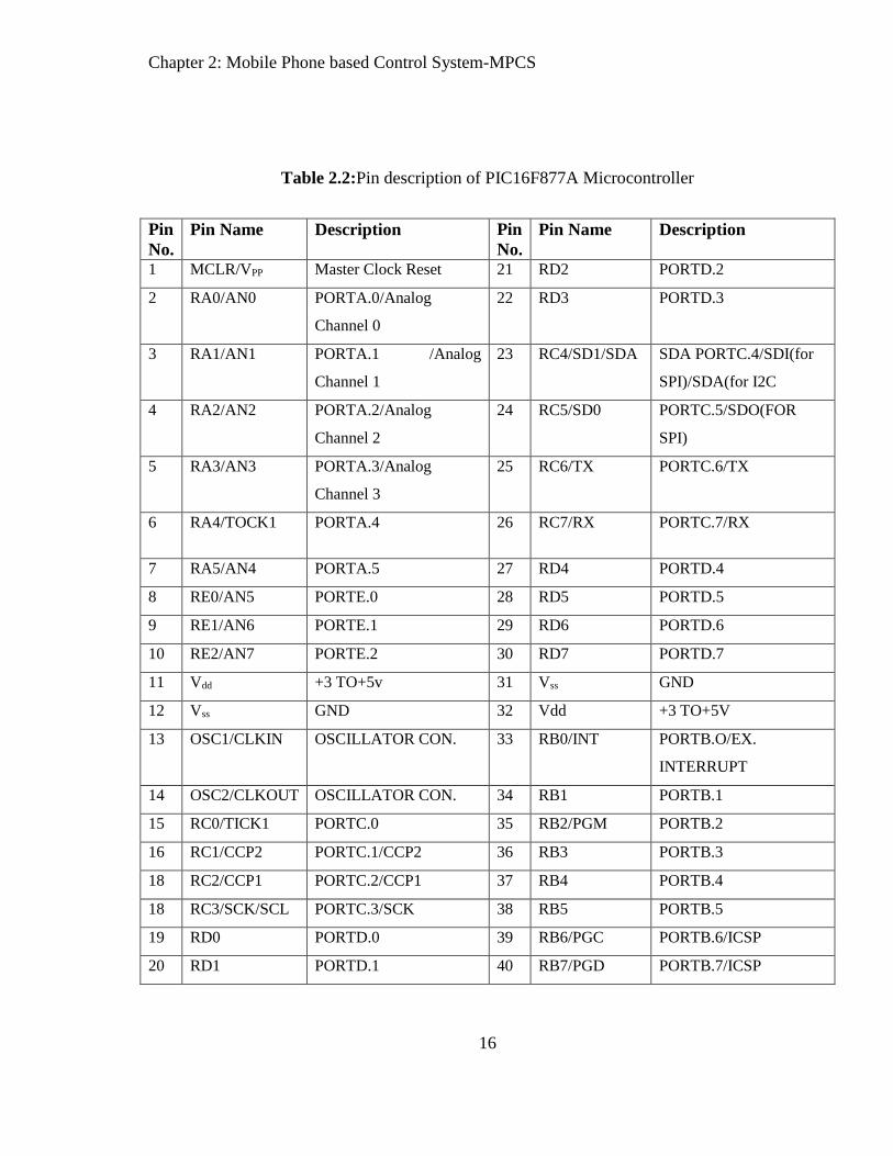
Table 2.2:Pin description of PIC16F877A Microcontroller
Pin
No.
Pin Name Description Pin
No.
Pin Name Description
1 MCLR/VPP Master Clock Reset 21 RD2 PORTD.2
2 RA0/AN0 PORTA.0/Analog
Channel 0
22 RD3 PORTD.3
3 RA1/AN1 PORTA.1 /Analog
Channel 1
23 RC4/SD1/SDA SDA PORTC.4/SDI(for
SPI)/SDA(for I2C
4 RA2/AN2 PORTA.2/Analog
Channel 2
24 RC5/SD0 PORTC.5/SDO(FOR
SPI)
5 RA3/AN3 PORTA.3/Analog
Channel 3
25 RC6/TX PORTC.6/TX
6 RA4/TOCK1 PORTA.4 26 RC7/RX PORTC.7/RX
7 RA5/AN4 PORTA.5 27 RD4 PORTD.4
8 RE0/AN5 PORTE.0 28 RD5 PORTD.5
9 RE1/AN6 PORTE.1 29 RD6 PORTD.6
10 RE2/AN7 PORTE.2 30 RD7 PORTD.7
11 Vdd +3 TO+5v 31 Vss GND
12 Vss GND 32 Vdd +3 TO+5V
13 OSC1/CLKIN OSCILLATOR CON. 33 RB0/INT PORTB.O/EX.
INTERRUPT
14 OSC2/CLKOUT OSCILLATOR CON. 34 RB1 PORTB.1
15 RC0/TICK1 PORTC.0 35 RB2/PGM PORTB.2
16 RC1/CCP2 PORTC.1/CCP2 36 RB3 PORTB.3
18 RC2/CCP1 PORTC.2/CCP1 37 RB4 PORTB.4
18 RC3/SCK/SCL PORTC.3/SCK 38 RB5 PORTB.5
19 RD0 PORTD.0 39 RB6/PGC PORTB.6/ICSP
20 RD1 PORTD.1 40 RB7/PGD PORTB.7/ICSP

Chapter 2: Mobile Phone based Control System-MPCS
17
2.3.3 Crystal oscillator
A crystal oscillator shown in Fig. 2.5 is an electronic oscillator circuit that uses the mechanical
resonance of a vibrating crystal of piezoelectric material to create an electrical signal with a very
precise frequency. This frequency is commonly used to keep track of time (as in quartz
wristwatches), to provide a stable clock signal for digital integrated circuits, and to stabilize
frequencies for radio transmitters and receivers. The most common type of piezoelectric
resonator used is the quartz crystal, so oscillator circuits incorporating them became known as
crystal oscillators, but other piezoelectric materials including polycrystalline ceramics are used
in similar circuits.
Figure: 2.5: Crystal oscillators.
Quartz crystals are manufactured for frequencies from a few tens of kilohertz to hundreds of
megahertz. More than two billion crystals are manufactured annually. Most are used for
consumer devices such as wristwatches, clocks, radios, computers, and cell phones. Quartz
crystals are also found inside test and measurement equipment, such as counters, signal
generators, and oscilloscopes [11].
2.3.4 Electrical relay
A relay shown in Fig. 2.6 is an electrical switch that uses an electromagnet to move the switch
from the OFF to ON position instead of a person moving the switch. It takes a relatively small
amount of power to turn on a relay but the relay can control something that draws much more
power. Ex: A relay is used to control the air conditioner in your home. The AC unit probably

Chapter 2: Mobile Phone based Control System-MPCS
18
runs off of 220VAC at around 30A. That's 6600 Watts! The coil that controls the relay may only
need a few watts to pull the contacts together. This is the schematic representation of a relay.
The contacts at the top are normally open (i.e. not connected). When current is passed through
the coil it creates a magnetic field that pulls the switch closed (i.e. connects the top contacts).
Usually a spring will pull the switch open again once the power is removed from the coil.
Fig. 2.6.Electrical relay
Relays (and switches) come in different configurations. Single Pole Single Throw (SPST) is the
simplest with only two contacts. Single Pole Double Throw (SPDT) has three contacts. The
contacts are usually labeled Common (COM), Normally Open (NO), and Normally Closed
(NC). The Normally Closed contact will be connected to the Common contact when no power is
applied to the coil. The Normally Open contact will be open (i.e. not connected) when no power
is applied to the coil. When the coil is energized the Common is connected to the Normally
Open contact and the Normally Closed contact is left floating. The Double Pole versions are the
same as the Single Pole version except there are two switches that open and close together.
Select a relay with contacts that can handle the voltage and current requirements of the load.
Keep in mind that some loads (such as motors) draw much more current when first turned on
than they do at steady state. Select a relay with a coil voltage and current that you can control
easily. Ex: If you want to turn on the AC unit with a 12VDC power supply get a 12VDC coil.
Coils will be rated for either AC or DC operation.

Chapter 2: Mobile Phone based Control System-MPCS
19
2.3.5 SIM300CZ tri-band modem
Designed for global market, SIM300CZ is a Tri-band GSM/GPRS engine that works on
frequencies of EGSM 900 MHz, DCS 1800 MHz and PCS 1900 MHz.SIM300CZ features
GPRS multi-slot class 10/class8capabilities and support the GPRS coding schemes CS-1, CS-2,
CS-3 and CS-4. Designed for global market, SIM300CZ is a Tri-band GSM/GPRS engine that
works on frequencies of EGSM 900 MHz, DCS 1800 MHz and PCS 1900 MHz.SIM300CZ
features GPRS multi-slot class 10/class8(optional)capability and support the GPRS coding
schemes CS-1, CS-2, CS-3 and CS-4 [9].
With a tiny configuration of 50mm x 33mm x 6.2mm, SIM300CZ can fit almost all the space
requirement in your industrial application, such as M2M, and mobile data communication
system etc. With the charge circuit integrated inside the SIM300CZ, it is very suitable for the
battery power application. The physical interface to the mobile application is made through a 60
pins DIP connector, which provides all hardware interfaces between the module and customers’
boards except the RF antenna interface.
The keypad and SPI display interface will give you the flexibility to develop customized
applications.
Serial port and Debug port can help you easily develop your applications.
Two audio channels include two microphones inputs and two speaker outputs. This can
be easily configured by AT command.
Charge interface
The SIM300CZ provides RF antenna interface with two alternatives: antenna connector and
antenna pad. The antenna connector is MURATA MM9329-2700. And customer’s antenna can
be soldered to the antenna pad. The SIM300CZ is designed with power saving technique, the
current consumption is as low as 2.5mA in SLEEP mode. The SIM300CZ is integrated with the

Chapter 2: Mobile Phone based Control System-MPCS
20
TCP/IP protocol, extended TCP/IP AT commands are developed for customers to use the
TCP/IP protocol easily, which is very useful for those data transfer application
Features:
Designed for global market, SIM300 is a Tri-band GSM/GPRS engine
Works on frequencies EGSM 900 MHz, DCS 1800 MHz and PCS 1900 MHz.
SIM300 features GPRS multi-slot class 10/ class 8 (optional) and supports the GPRS
coding schemes
CS-1, CS-2, CS-3 and CS-4.With a tiny configuration of 40mm x 33mm x 2.85mm ,
SIM300 can fit almost all the space requirements in your applications,
such as smart phone, PDA phone and other mobile devices
Features of GSM Kit:
This GSM modem is a highly flexible plug and play quad band GSM modem
Integration to RS232.
Supports features like Voice, Data/Fax, SMS,GPRS and integrated TCP/IP stack.
Control via AT commands(GSM 07.07,07.05 and enhanced AT commands)
Use AC – DC Power Adaptor with following ratings · DC Voltage : 12V /1A
Current Consumption in normal operation 250mA, can rise up to 1Amp while
transmission.
Interfaces
RS-232 through D-TYPE 9 pin connector,
Serial port baud rate adjustable 1200 to115200 bps (9600 default)
BRK connector for MIC & SPK, SIM card holder
Power supply through DC socket
SMA antenna connector and Murata Antenna ( optional)
LED status of GSM / GPRS module.

Chapter 2: Mobile Phone based Control System-MPCS
21
2.3.6 LCD display (16X2)
In embedded systems it is difficult to find status and errors generated by system software
running inside of microcontroller. It is also necessary in so many other applications where we
have to show results to users so that they can use system effectively. So there is a need of a
display unit. There are more than one ways of displaying status or results of the system and
LCD shown in Fig. 2.7 is one of these ways.
Fig. 2.7: LCD display
In this system, the used LCD having 16 columns and 2 rows. This is based on HD44780 LCD
controller. HD44780 is a generic dot matrix LCD controller made by Hitachi. This controller is
installed on other sizes of LCDs like 16×1, 16×4, 20×2, 20×4 etc. The interfacing between LCD
and PIC16F877A microcontroller is shown in Fig. 2.8, where the pin diagram of LCD is also
presented.

Chapter 2: Mobile Phone based Control System-MPCS
22
Fig. 2.8: LCD Display interfacing with PIC16F877A
Table 2.3: Pin-Diagram of LCD display
Pin Symbol Function
1 Vss ground (0 V)
2 Vdd power (4.5 – 5.5 V)
3 Vo contrast adjustment
4 RS H/L register select signal
5 R/W H/L read/write signal
6 E H/L enable signal
7-14 DB0 – DB7 H/L data bus for 4- or 8-bit mode
15 A (LED+) backlight anode
16 K (LED-) backlight cathode

Chapter 2: Mobile Phone based Control System-MPCS
23
2.3.7 ULN2003 driver
The ULN2003A is an array of seven NPN Darlington transistors capable of 500mA, 50V
output. It features common-cathode fly back diodes for switching inductive loads. It can come
in PDIP, SOIC, SOP or TSSOP packaging. In the same family are ULN2002A, ULN2004A, as
well as ULQ2003A and ULQ2004A, designed for different logic input levels.
Fig.2.9: ULN2003 relay driver IC
ULN2003 is known for its high-current, high-voltage capacity. The drivers can be paralleled for
even higher current output. Even further, stacking one chip on top of another, both electrically
and physically, has been done. Generally it can also be used for interfacing with stepper motor,
where the motor requires high ratings which cannot be provided by other interfacing devices.

Chapter 2: Mobile Phone based Control System-MPCS
24
Main specifications:
500 mA rated collector current (single output)
50 V output (there is a version that supports 100 V output)
Includes output fly back diodes
Inputs compatible with TTL and 5-V CMOS logic
2.4 Description of the software
For design and implementation of our MPCS we used MikroC Pro for PIC for programming and
Proteus 7.1 for simulation MPCS. The description of this software is following:
2.4.1 MikroC Pro for PIC
The MikroC PRO for PIC is a powerful, feature-rich development tool for PIC microcontrollers.
It is designed to provide the programmer with the easiest possible solution to developing
applications for embedded systems, without compromising performance or control.PIC and C fit
together well: PIC is the most popular 8-bit chip in the world, used in a wide variety of
applications, and C, prized for its efficiency, is the natural choice for developing embedded
systems. MikroC PRO for PIC provides a successful match featuring highly advanced IDE,
ANSI compliant compiler, broad set of hardware libraries, comprehensive documentation, and
plenty of ready-to-run examples [13].
Special features of MikroC Pro for PIC:
a. MikroC PRO for PIC allows you to quickly develop and deploy complex applications:
b. Write your C source code using the built-in Code Editor(Code and Parameter Assistants,
Code Folding, Syntax Highlighting, Auto Correct, Code Templates, and more.)
c. Use included MikroC PRO for PIC libraries to dramatically speed up the development:
data acquisition, memory, displays, conversions, communication etc.
Chapter 2: Mobile Phone based Control System-MPCS
25
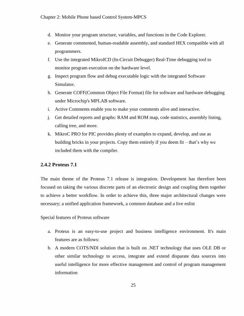
d. Monitor your program structure, variables, and functions in the Code Explorer.
e. Generate commented, human-readable assembly, and standard HEX compatible with all
programmers.
f. Use the integrated MikroICD (In-Circuit Debugger) Real-Time debugging tool to
monitor program execution on the hardware level.
g. Inspect program flow and debug executable logic with the integrated Software
Simulator.
h. Generate COFF(Common Object File Format) file for software and hardware debugging
under Microchip's MPLAB software.
i. Active Comments enable you to make your comments alive and interactive.
j. Get detailed reports and graphs: RAM and ROM map, code statistics, assembly listing,
calling tree, and more.
k. MikroC PRO for PIC provides plenty of examples to expand, develop, and use as
building bricks in your projects. Copy them entirely if you deem fit – that’s why we
included them with the compiler.
2.4.2 Proteus 7.1
The main theme of the Proteus 7.1 release is integration. Development has therefore been
focused on taking the various discrete parts of an electronic design and coupling them together
to achieve a better workflow. In order to achieve this, three major architectural changes were
necessary; a unified application framework, a common database and a live enlist
Special features of Proteus software
a. Proteus is an easy-to-use project and business intelligence environment. It's main
features are as follows:
b. A modern COTS/NDI solution that is built on .NET technology that uses OLE DB or
other similar technology to access, integrate and extend disparate data sources into
useful intelligence for more effective management and control of program management
information

Chapter 2: Mobile Phone based Control System-MPCS
26
c. Possesses the ability to integrate information both horizontally and vertically, organize
data by user role and content and allow access to that data in accordance with position in
the organization, user role and need to know
d. Reduces life-cycle and support costs associated with business intelligence through an
easy-to-use template-based configuration that eliminates the need for specialized
development or hard-coding, allowing for rapid deployment and almost immediate ROI
e. Integrates data from disparate systems into a consolidated view that can be aggregated at
all levels for all stakeholders within and across the program team and the enterprise. The
stakeholders can drill down into the data and summarize the data at will to quickly
identify problems and trends
f. Provides virtually unlimited tailored views and reports to program specific needs using
the configurable user interface and business logic that interfaces with any existing OLE
DB-compatible table structure
g. Transforms data from any OLE DB compatible data source or format and be able to
transform that data for use without having to rekey the data. Data from different sources
should be easily compared to find mismatches and disparities
h. Organizes previously stove-piped information in a cohesive and intelligent manner. For
example, users need to be able to create integrated views of cost, schedule, risk, financial
and any other relevant program related data at any level of detail. Views should be saved
and used across the organization, a subunit of the organization or solely for a specific
user or set of users

Chapter 3: Software used in MPCS
27
Chapter 3
Software Part of MPCS
This chapter describes the detailed software part of MPCS, where two software tools were used,
such as, Proteus professional simulation tool and MicroC programming tool.
3.1 Description of Proteus
The Proteus professional simulation tool, that is to say, Proteus Design Suite (PDS) is wholly
unique in offering the ability to co-simulate both high and low level micro-controller codes in the
context of a mixed-mode SPICE circuit simulation. Using this virtual system modeling facility,
any kind of microcontroller based system model can be simulated with its real time data in order
to design and implement the system practically with lower costs [3], [6], and [10].
Usually, simulation of a designed model using PDS tool provides huge advantages for the future
implementations in setting hardware [10]. The reason is that, PDS always works on the real time
data of the different electrical components, in which the simulation outcome of the PDS of a
designed model is closed to similar to the original one. On the other hand, the PDS outcome can
be varied with varying the PDS design of a desired model within a very short time. Designing a
hardware model that is to say, physical setup of a hardware model is always expensive in cost
which might be increased if the proper electrical components with ratings are not determined. In
this case, PDS tool may provide optimistic solution that resulting an economical hardware
designing of a desired model. In addition, PDS combines mixed mode SPICE circuit simulation,
animated components and microprocessor models to facilitate co-simulation of complete

Chapter 3: Software used in MPCS
28
microcontroller based designs. For the first time ever, it is possible to develop and test such
designs before a physical prototype is constructed. This is possible because PDS can easily
interact with the designing of screen based indicators, such as, LED and LCD displays and
actuators, such as, switches and buttons. The simulation takes place in real time: a 1GMHz
Pentium III can simulate a basic 8051 system clocking at over 12MHz. PDS also provides
extensive debugging facilities including breakpoints, single stepping and variable display for
both assembly code and high level language source.
3.1.1 Overview of the Proteus Design Suite
Initially, starting the program that can be possible by clicking on the ISIS Professional v7.1 icon
from desktop of personal computer. Thus, starting interface is appeared according to the Fig. 3.1.
3.1.2 Circuit Construction and Assembly
Prior to circuit construction, it is necessary to identify first the required components in the
circuit. For example, in executing an 8-bit running light, the components needed are:
i. PIC16F877
ii. LED
iii. Resistor
iv. Capacitor
v. Power Supply Terminals / Grounding

Chapter 3: Software used in MPCS
29
Fig. 3.1: Overview of Proteus software.
3.1.3 PIC16F877A parameter setting
The PIC16F877A property panel can be similarly obtained by right clicking the PIC and
selecting “Edit Component”. The PIC parameters like oscillator frequency, program
configuration word and other properties should be appropriately supplied. The program code in
hex file should be loaded in the program file section. The summary of the entire procedure for
parameter setting is shown in Fig. 3.2.
3.1.4 Simulation
After defining all the various parameters in the PIC and the other components and also loading
the hex file in the controller, we can start the simulation by clicking the PLAY button on the
bottom panel of the PDS.

Chapter 3: Software used in MPCS
30
Fig.3.2: PIC parameter setting on Proteus.

Chapter 3: Software used in MPCS
31
3.2 Proteus Layout of MPCS
The MPCS layout is presented in the Proteus software that is shown in Fig.3.3
Fig.3.3: MPCS shown in Proteus.
3.3 MikroC programming tools
MikroC is a powerful, feature rich development tool for PIC microcontrollers. It is designed to
provide the customer with the easiest possible solution for developing application for embedded
system, without compromising performance or control. PIC is the most popular 8-bit chip in the
world, used in a wide variety of application, and C, prized for its efficiency, is the natural choice
for developing embedded systems. MikroC provides a successful match featuring highly
advanced IDE, ANCI compliant compiler, broad set of hardware libraries, comprehensive
documentation, and plenty of ready-to run examples.

Chapter 3: Software used in MPCS
32
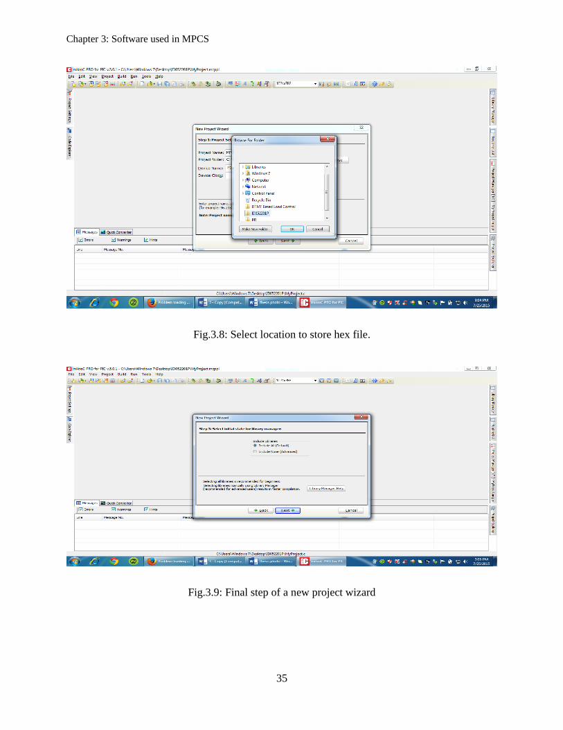
3.3.1 Creating a new project
To create a new project in MikroC Pro for PIC, a new window must be opened that is shown in
Fig.3.4. Then, a new project wizard needs to be opened (see Fig. 3.5) and follow Fig. 3.6. Now,
define a project name according to Fig. 3.7 and select a folder on desktop to store the hex file
(see Fig. 3.8). At last, follow the final step of creating a new project wizard (Fig. 3.9).
Fig.3.4: New wizard of MikroC Pro for PIC Microcontroller
3.3.2 Coding template
Fig.3.10 shows the coding template where any program can be written. In this template, program
(or, coding) of MPCS has been written and it is successfully built in the project.

Chapter 3: Software used in MPCS
33
Fig.3.5: Creating a new project in MikroC Pro for PIC

Chapter 3: Software used in MPCS
34
Fig.3.6: Creating a new project wizard in MikroC Pro for PIC on process.
Fig.3.7: Defining a file name.
Chapter 3: Software used in MPCS
35
Fig.3.8: Select location to store hex file.
Fig.3.9: Final step of a new project wizard

Chapter 3: Software used in MPCS
36
Fig.3.10: Coding of MPCS and built in condition.
3.4 AT command
These commands are used to control MODEMs. AT is the abbreviation for Attention. These
commands come from Hayes commands that were used by the Hayes smart modems. The Hayes
commands started with AT to indicate the attention from the MODEM. The dial up and wireless
MODEMs (devices that involve machine to machine communication) need AT commands to
interact with a computer. These include the Hayes command set as a subset, along with other
extended AT commands.

Chapter 3: Software used in MPCS
37
AT commands with a GSM/GPRS MODEM or mobile phone can be used to access following
information and services:
1. Information and configuration pertaining to mobile device or MODEM and SIM card.
2. SMS services.
3. MMS services.
4. Fax services.
5. Data and Voice link over mobile network.
3.4.1 Types of AT command
There are four types of AT commands, which are presented in Fig. 3.11.
Fig.3.11: Classifications of AT commands
The detailed discussion about the four AT commands is stated below:
1. Test commands - used to check whether a command is supported or not by the
MODEM.
SYNTAX: AT<command name>=?
For example: ATD=?
2. Read command - used to get mobile phone or MODEM settings for an operation.
SYNTAX: AT<command name>?
For example: AT+CBC?

Chapter 3: Software used in MPCS
38
3. Set commands - used to modify mobile phone or MODEM settings for an operation.
SYNTAX: AT command name value1, value2, ,valueN
Some values in set commands can be optional.
4. Execution commands - used to carry out an operation.
SYNTAX: AT command name parameter1, parameter2 parameterN
The read commands are not available to get value of last parameter assigned in execution
commands because parameters of execution commands are not stored.
Some of SMS AT commands are given bellow:
Command Description
AT+CSMS Select message service.
AT+CPMS Preferred message storage
AT+CMGF Message format
AT+CSCA Service center address
AT+CSMP Set text mode parameter
AT+CSDH Show text mode parameter
AT+CSCB Select cell broadcast message type
AT+CSAS Save setting
AT+CRES Restore setting
AT+CMGW Write message to memory
AT+CMGR Read message
AT+CMGW Write message
3.5 Pseudo Code of MPCS
1. Initialization ()
a. Initialize LCD display
b. Initialize UART port of microcontroller PIC16F877A
c. Initialize EEPROM memory at 0X00

Chapter 3: Software used in MPCS
39
2. Define
a. Input Port at PORTA
b. Output LCD display Port at PORTB
c. PORTA as digital input
d. Devices at output SMS PORTD
e. Array to store messages
3. Generate Message (){
a. Check UART Data is ready
b. Send AT Command to Ready Message
c. If Message is there
4. Main () {
a. define
b. Call function Initialization ();
C.Display load status on LCD
c. GenearteMessage ();
d. If Received Call () ==1
i. Compare sent message string with the device defined strings
ii. PORTA = PORTA & 0b00001111;
if(PORTA==0b00000000) DTMF_Code = 0;
else if(PORTA==0b00001000) DTMF_Code = 1;
else if(PORTA==0b00000100) DTMF_Code = 2;
else if(PORTA==0b00001100) DTMF_Code = 3;
else if(PORTA==0b00000010) DTMF_Code = 4;
else if(PORTA==0b00001010) DTMF_Code = 5;
else if(PORTA==0b00000110) DTMF_Code = 6;
else if(PORTA==0b00001110) DTMF_Code = 7;
else if(PORTA==0b00000001) DTMF_Code = 8;
else if(PORTA==0b00001001) DTMF_Code = 9;

Chapter 3: Software used in MPCS
40
else DTMF_Code = 0;
END
}
3.6 Program Coding
// DTMF Based load control
// PIC 16F877A
//X_Tal: 8MHz
// LCD module connections
sbit LCD_RS at RB7_bit;
sbit LCD_EN at RB6_bit;
sbit LCD_D4 at RB5_bit;
sbit LCD_D5 at RB4_bit;
sbit LCD_D6 at RB3_bit;
sbit LCD_D7 at RB2_bit;
sbit LCD_RS_Direction at TRISB7_bit;
sbit LCD_EN_Direction at TRISB6_bit;
sbit LCD_D4_Direction at TRISB5_bit;
sbit LCD_D5_Direction at TRISB4_bit;
sbit LCD_D6_Direction at TRISB3_bit;
sbit LCD_D7_Direction at TRISB2_bit;
// End LCD module connections
int DTMF_Code = 0;
int D_port1,D_port2;
shortold_status = 1;

Chapter 3: Software used in MPCS
41
void SMS_Int(void)
{
UART1_Write_Text("AT\r");
Delay_ms(500);
UART1_Write_Text("AT+cmgf=1\r");
Delay_ms(500);
UART1_Write_Text("AT+cmgs=");
UART1_Write((char)'"');
UART1_Write_Text("01716710375");
UART1_Write((char)'"');
UART1_Write((char)13);
UART1_Write((char)10);
Delay_ms(500);
}
char SMS[] = "Load1: ; Load2: ; Load3: ; Load4: .";
void main()
{
// I/O settings...
TRISA = 0xFF; // set all as input
TRISD = 0x00;// output settings
PORTD = 0x00;
ADCON0 = 0x00;
ADCON1 = 0x07; // set all digital i/o
CMCON = 0x07;// comparator off
Lcd_Init();
Lcd_Cmd(_LCD_CLEAR);
Lcd_Cmd(_LCD_CURSOR_OFF);
Delay_ms(100);
Lcd_Out(1,1,"Debashish Das");

Chapter 3: Software used in MPCS
42
Lcd_Out(2,1,"ID:052201P");
PORTD = 0x00;
Delay_ms(3000);
Lcd_Cmd(_LCD_CLEAR);
Lcd_Out(1,1,"L1:");
Lcd_Out(1,9,"L2:");
Lcd_Out(2,1,"L3:");
Lcd_Out(2,9,"L4:");
PORTD = 0x00;
UART1_Init(9600); //initialize UART at baud rate 9600
Delay_ms(100);
while(1)
{ // continuous program...
UART1_Write_Text("AT\r\n");
Delay_ms(500);
PORTA = PORTA & 0b00001111;
if(PORTA==0b00000000) DTMF_Code = 0;
else if(PORTA==0b00001000) DTMF_Code = 1;
else if(PORTA==0b00000100) DTMF_Code = 2;
else if(PORTA==0b00001100) DTMF_Code = 3;
else if(PORTA==0b00000010) DTMF_Code = 4;
else if(PORTA==0b00001010) DTMF_Code = 5;
else if(PORTA==0b00000110) DTMF_Code = 6;
else if(PORTA==0b00001110) DTMF_Code = 7;
else if(PORTA==0b00000001) DTMF_Code = 8;
else if(PORTA==0b00001001) DTMF_Code = 9;
else DTMF_Code = 0;
}

Chapter 3: Software used in MPCS
43
//char SMS[] = "Load1: ; Load2: ; Load3: ; Load4: .";
if(RD0_bit)
{
SMS[6] = 'O';
SMS[7] = 'N';
SMS[8] = ' ';
}
else
{
SMS[6] = 'O';
SMS[7] = 'F';
SMS[8] = 'F';
}
if(RD1_bit)
{
SMS[17] = 'O';
SMS[18] = 'N';
SMS[19] = ' ';
}
else
{
SMS[17] = 'O';
SMS[18] = 'F';
SMS[19] = 'F';
}
//char SMS[] = "Load1: ; Load2: ; Load3: ; Load4: .";
if(RD2_bit)
{
SMS[27] = 'O';
SMS[28] = 'N';

Chapter 3: Software used in MPCS
44
SMS[29] = ' ';
}
else
{
SMS[27] = 'O';
SMS[28] = 'F';
SMS[29] = 'F';
}
//char SMS[] = "Load1: ; Load2: ; Load3: ; Load4: .";
if(RD3_bit)
{
SMS[38] = 'O';
SMS[39] = 'N';
SMS[40] = ' ';
}
else
{
SMS[38] = 'O';
SMS[39] = 'F';
SMS[40] = 'F';
}
D_port1 = PORTD & 0b00001111;
if(D_port1 != D_port2)
{
//Generation of SMS
SMS_Int(void);
Delay_ms(100);
UART1_Write_Text(SMS);
UART1_Write((char)26); //send Control + Z
UART1_Write((char)13);

Chapter 3: Software used in MPCS
45
UART1_Write((char)10);
}
// for Load 1
if(DTMF_Code==1)
{
RD0_bit = 1; // turn load 1 on
Lcd_Out(1,4,"ON ");
Delay_ms(1000);
}
else if(DTMF_Code==2)
{
RD0_bit = 0; // turn load 1 off
Lcd_Out(1,4,"OFF");
Delay_ms(1000);
}
// for Load 2
else if(DTMF_Code==3)
{
RD1_bit = 1;
Lcd_Out(1,12,"ON ");
Delay_ms(1000);
}
else if(DTMF_Code==4)
{
RD1_bit = 0;
Lcd_Out(1,12,"OFF");
Delay_ms(1000);
}
// for Load 3
else if(DTMF_Code==5)

Chapter 3: Software used in MPCS
46
{
RD2_bit = 1;
Lcd_Out(2,4,"ON ");
Delay_ms(1000);
}
else if(DTMF_Code==6)
{
RD2_bit = 0;
Lcd_Out(2,4,"OFF");
Delay_ms(1000);
}
// for Load 4
else if(DTMF_Code==7)
{
RD3_bit = 1;
Lcd_Out(2,12,"ON ");
Delay_ms(1000);
}
else if(DTMF_Code==8)
{
RD3_bit = 0;
Lcd_Out(2,12,"OFF");
Delay_ms(1000);
}
else
{
PORTD = PORTD;
Delay_ms(1000);
}

Chapter 3: Software used in MPCS
47
if(DTMF_Code == 9)
{
//send SMS
SMS_Int(void);
Delay_ms(100);
UART1_Write_Text(SMS);
Delay_ms(3000);
UART1_Write((char)26);//send Control + Z
UART1_Write((char)13);
UART1_Write((char)10);
DTMF_Code = 0;
}
D_port2 = D_port1;
Delay_ms(1000);
}//while
}//void

Chapter 4: Experimental studies
48
Chapter 4
Experimental studies
This chapter presents the detailed experimental studies of MCPS including the observation of
current load status.
4.1 Experimental studies
In this section, it is discussed about the physical construction and operations of the proposed
system. There is DTMF circuit that receives signal from user’s mobile and send data into
microcontroller. Microcontroller read the information and takes necessary action to control the
loads. A GSM modem is used that sends message to user’s mobile unit about the current status
of the remote loads. However, to implement the whole system, part by part implementation was
observed first. As an experimental study, the entire observation is divided into three ways: (i)
implementation and observation of DTMF circuit, (ii) controlling and displaying loads using
mobile phone, (iii) final implementation of MPCS. For more clarification, the total observation
is discussed below:
4.1.1 Implementation and observation of DTMF circuit
In order to implement the entire system, initially the DTMF circuit has been implemented in a
small breadboard as an experimental basis. In this case, the four loads are replaced by four
LEDs nominated by L1, L2, L3 and L4. In Fig. 4.1, it is found that whenever user’s mobile

Chapter 4: Experimental studies
49
made contact with remote mobile, then if the keypad is pressed by “1” from the user’s mobile,
the Load1 (assigned by L1) is ON. On the other hand, Load1 is OFF if the keypad is pressed by
“2”. Similar tasks are performed sequentially for the rest of Loads (i.e., L2, L3, and L4). These
phenomena have been performed according to the DTMF test data sheet mentioned in Table 4.1.
Fig.4.1: Implementation and observation of DTMF circuit.
4.1.2 Controlling and displaying loads using mobile phone
The circuit was made for controlling loads and displaying their current status in the bread board
as an experimental basis, which has been presented in Fig. 4.2. In this circuit, the outputs
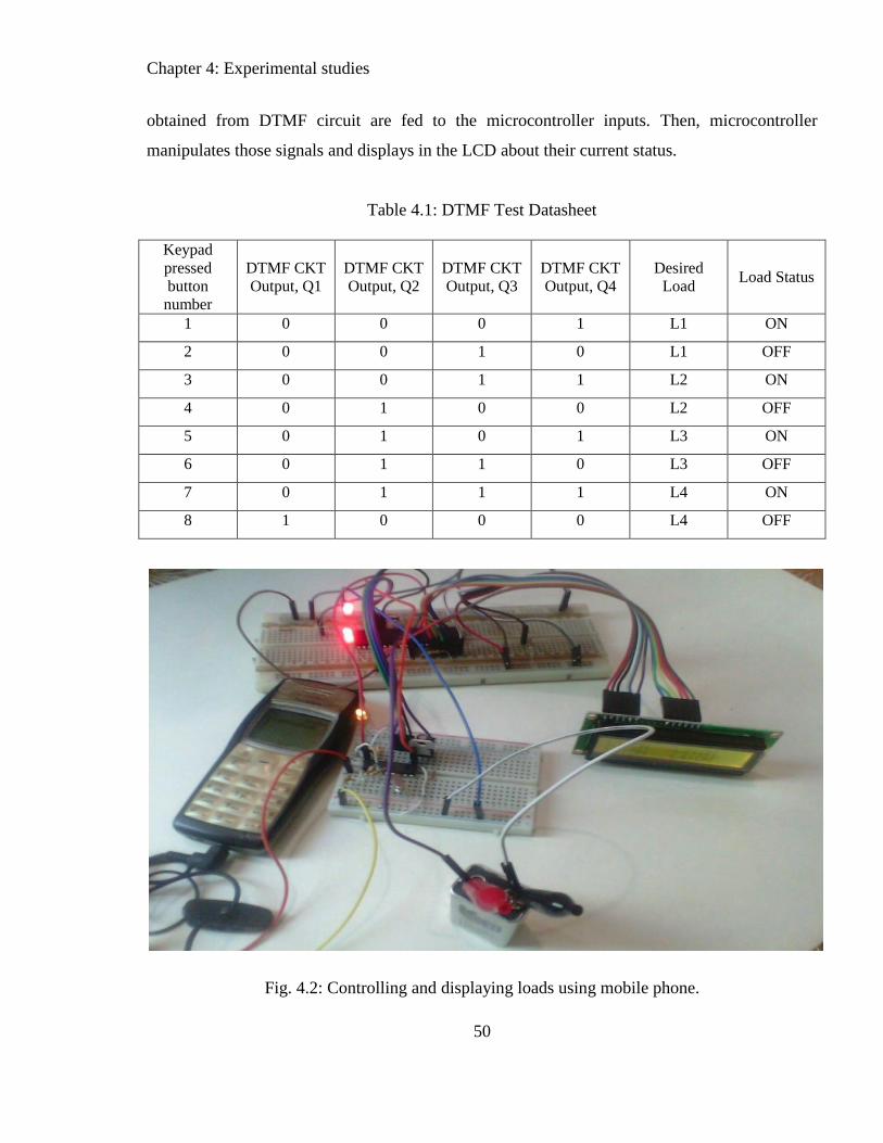
Chapter 4: Experimental studies
50
obtained from DTMF circuit are fed to the microcontroller inputs. Then, microcontroller
manipulates those signals and displays in the LCD about their current status.
Table 4.1: DTMF Test Datasheet
Keypad
pressed
button
number
DTMF CKT
Output, Q1
DTMF CKT
Output, Q2
DTMF CKT
Output, Q3
DTMF CKT
Output, Q4
Desired
Load Load Status
1 0 0 0 1 L1 ON
2 0 0 1 0 L1 OFF
3 0 0 1 1 L2 ON
4 0 1 0 0 L2 OFF
5 0 1 0 1 L3 ON
6 0 1 1 0 L3 OFF
7 0 1 1 1 L4 ON
8 1 0 0 0 L4 OFF
Fig. 4.2: Controlling and displaying loads using mobile phone.

Chapter 4: Experimental studies
51
Fig. 4.3: Final implementation of MPCS
Chapter 4: Experimental studies
52
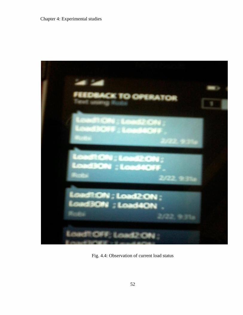
Fig. 4.4: Observation of current load status

Chapter 4: Experimental studies
53
Table 4.2: Results of MPCS
Time requirement for operating the loads in case of MPCS using Hardware setup and Software
simulation.
Digit
From
Mobile
Keypad
Q1Q2Q3Q4 Desired
Load
Status of Loads Required
Time by
Hardware
Setup
(Second)
Required
Time by
Software
Simulation
(Second)
Load-
1
Load-
2
Load-
3
Load-
4
1 0001 Load-1 ON OFF OFF OFF 5 1.0
2 0010 Load-1 OFF OFF OFF OFF 5 1.0
3 0011 Load-2 OFF ON OFF OFF 5 1.0
4 0100 Load-2 OFF OFF OFF OFF 4 1.0
5 0101 Load-3 OFF OFF ON OFF 4.5 1.0
6 0110 Load-3 OFF OFF OFF OFF 6 1.0
7 0111 Load-4 OFF OFF OFF ON 5 1.0
8 1000 Load-4 OFF OFF OFF OFF 5 1.0
From the above table, it can be observed that, to operate an individual loads among the four, the
required time for MPCS in hardware setup is higher than that of proteus software simulations.
The reason is that, electrical devices need an amount of time to convey the signal from one
place another place. Moreover, they have some temperature effect in resistivity, whereas,
software simulation is totally out of such constraints.
4.1.3 Final Implementation of MPCS
Chapter 4: Experimental studies
54
Before going to the final implementations, two experiments have been conducted successfully
mentioned in Subsections 4.1.2 and 4.1.3. After that, finally, the proposed system-MPCS
implemented in a Vero board presented in Fig. 4.4. Here, four electrical lamps were used as the
remote electrical loads.
4.1.4Observation of current load status
Fig.4.4 shows a complete prototype version of MPCS (Mobile Phone based Control System).
From this prototype version, the current load status from LCD display can be observed.
Moreover, we can see the current status of different electrical loads by auto generated SMS
shown in Fig.4.5.

Chapter 5: Conclusion
55
Chapter 5
Conclusion
5.1 Conclusion
In this report, a mobile phone based control system (MPCS) has been developed in order
to communicate with the remote loads automatically. This project uses the DTMF
technology involving GSM modem, mobile key pad, electrical relay, and so on.
Particularly, DTMF generates the signal through the mobile key pad, which is very
efficient for very long distance data transmission. The entire project has been formulated
by Microcontroller with its program coding.
In combination of GSM modem with DTMF, microcontroller can easily provide the
present status of the remote electrical loads. Therefore, anyone can get the current status
about the remote loads individually whether it being ON/OFF mode from the sender end.
Thus, using the proper handling of offices or household electrical appliances, where
people often used to forget to switch off, energy saving can be possible.
No expert human is required at the remote places to be made contact with the sender end.
Further extension for the number of remote electrical loads can be possible in MPCS any
time. It can be noted that, our project MPCS has a very good future for our country’s
respect whether it could be established commercially at the industrial areas. Thus, our
Chapter 5: Conclusion
56
industrial management will be more dynamic as well as the production cost will be
reduced.
According to our knowledge, this project is not only developed first in DUET, but also a
promising work in the respect of Bangladesh also. In this work, I have successfully
implemented a prototype multiple load controlling system by mobile phone, where a LCD
display was used to observe the present status of the remote loads whether it is in
ON/OFF mode.
5.2 Recommendation for future work
For future work, hopefully 3.5G network will be used for data visualization in operator’s
mobile and after implementation the status of loads’ physical condition can be known.

57
References
[1] M.M. Rashid. “ Design and Development of a Universal Three-Phase Control Module
Operated by Cell Phone,” M. Engg. Project Report, EEE dept. of DUET,2009.
[2] T. Begum, “ Design and Development of Activation and Monitoring of Home
Automation System via SMS though Microcontroller,” M.Sc. Engg. Thesis Report, EEE
dept. of DUET, 2010.
[3] C.K Das, M. Sanaullah, H.M.G Sarawor and M. M. Hasan, “ Development of a Cell
Phone based Remote Control System : an effective Switching System for Home and
Office Appliances,”International Journal of Electrical and Computer SciencesIJECS-
IJENS, vol. 9, no. 10, 2009
[4] Coskun and H. Ardam, “ A Remote Controller for Home and Office Appliances by
Telephone,” IEEE Transaction on Consumer Electronics, vol. 44, no. 4, pp. 1291-1297,
November 1998.
[5] E. ong, “A Phone based Remote Controller for Home and Office Automation,” IEEE
Transaction on Consumer Electronics, vol. 40, no. 1, pp. 28-33, February 1995.
[6] M Rahman, A. H. M. Z. Karim, F. Khan,G Matin, “Microcontroller Based Home
Security and Load Controlling Using GSM Technology,” International Journal of
Computer Network and Information Security, vol. 4, pp. 29-36,2015.
[7] M. Amanullah, “ Microcontroller Based Reprogrammable Digital Door Lock Security
System by Using Keypad & GSM Technology,” IQSR Journal of Electrical and
Electronic Engineering, vol. 4, issue 6, pp. 38-42, 2013.
[8] Sakti Bajaj Sandep, “Speed regulation DC drive using cell communication,”
International Journal of Soft Computing and Engineering (IJSCE), vol. 3, issue 1, March
2013.
[9] http://www.sim.com

58
[10] M. Ahmed, Faruki H, S. Ahmed and M.S. Harsoliya “ 3G based industrial automation
using GSM communication ,” International Journal of Research in Environmental science
and Technology, vol. 1, issue 2, pp. 16-23,2011
[11] http://www.ti.com/crystal_osci
[12] A tutorial on Microcontroller: Microchip 16F87XA Datasheet, Microchip Tech Inc, 2003.
[13] http://www.mikroe.com


![CONTROL SYSTEM [FS] 01–40B CONTROL SYSTEM [FS] · 01–40b control system [fs] control system component location index ... control system [fs] 01–40b–5 01–40b control system](https://static.fdocuments.net/doc/165x107/5acfe16f7f8b9a6c6c8da621/control-system-fs-0140b-control-system-fs-40b-control-system-fs-control.jpg)

![Optical and Electrical Properties of TTF-MPcs€¦ · Optical and Electrical Properties of TTF-MPcs ... well as for organic solar cells (OSC) [2]. ... in many applications, such as](https://static.fdocuments.net/doc/165x107/5f0859bd7e708231d421939c/optical-and-electrical-properties-of-ttf-mpcs-optical-and-electrical-properties.jpg)


