Design and implementation of AD9361-based software radio ...
14
RESEARCH Open Access Design and implementation of AD9361- based software radio receiver Feng Tian * , Hanqing Li and Liangchen Yuan Abstract Existing software radio platforms constructed by discrete devices have many disadvantages, such as high power consumption, high cost, and poor portability. In this study, an AD9361-based software radio communication system was designed on the basis of the zero-IF bandpass sampling software radio structure to solve the poor universality and expansibility problem of traditional software radio receivers. In the AD9361-based software radio communication system, the influences of channels on received signals and the inter-symbol interference caused by the multipath configuration are offset and eliminated by the minimum mean-squared error (MMSE) equalization algorithm. The simulation analyses on the core functions, including group detection, frame synchronization, channel estimation, and frequency-domain equilibrium, of the designed receiver was performed by ModelSim. The receiving functions of the software radio were realized by the core radio frequency (RF) board of AD9361 and the digital baseband development board of ZC706. The signal frequency spectra received and sent by the designed receiver overlap on the basis of the joint debugging and testing of the RF and digital baseband modules. Test results demonstrate that the designed software radio receiver has a reasonable structural design and can meet the design requirements in terms of overall performance. Additionally, the repeated development process of traditional software radio receivers is simplified, and the integration level and expansibility of the system can be improved. The results can provide valuable references for the development of universal software radio receivers. Keywords: Software radio, Receiver, AD9361, Frequency-domain equalization, Channel estimation 1 Introduction Software radio has overcome the disadvantage that previous communication platforms with different communication functions and frequency bands cannot communicate mutu- ally. Existing software radio platforms are constructed by discrete devices, which are constrained by high power con- sumption and high cost. This situation not only requires technicians to be experienced in hardware design and radio frequency (RF) signal processing, but it also poses high ac- cess requirements for software. Given the coexistence of 3G and 4G communication standards, and even that of 5G, there are multiple frequency bands around the world. Trad- itional software radio designs require different hardware platforms to support varied communication protocols and frequency bands, and they require long development periods and high design costs. Andrews et al. [1] suggested the use of a mixer as the first-level structure of a software radio to reduce noise at the cost of power with the supply voltage of the baseband low-noise amplifier increased. Murphy et al. (2012) put forward the use of a noise-canceling technology as the software radio structure. Useful sig- nals were enhanced by increasing the auxiliary chan- nels and offset noises at the output terminal, thus improving the noise reduction capability and the overall performance of the software radio system [2]. Zhang et al. propounded a software radio technique that can eliminate the spatial incident angle interfer- ence and frequency interference in signal filtering [3]. Loubser and Swart [4] encoded two existing CR-specific media access control protocols by using a CR-specific simulator. Kamaleldin and Ahmed put forward that hardware platforms of software radio system which support many wireless standards could be realized by dynamical program reconfiguration [5]. Marwanto et al. [6] proposed ARDUINO UNO and © The Author(s). 2019 Open Access This article is distributed under the terms of the Creative Commons Attribution 4.0 International License (http://creativecommons.org/licenses/by/4.0/), which permits unrestricted use, distribution, and reproduction in any medium, provided you give appropriate credit to the original author(s) and the source, provide a link to the Creative Commons license, and indicate if changes were made. * Correspondence: [email protected] College of Communication and Information Engineering, Xi’an University of Science and Technology, Xi’an, China Tian et al. EURASIP Journal on Wireless Communications and Networking (2019) 2019:95 https://doi.org/10.1186/s13638-019-1420-6
Transcript of Design and implementation of AD9361-based software radio ...

RESEARCH Open Access
Design and implementation of AD9361-based software radio receiverFeng Tian*, Hanqing Li and Liangchen Yuan
Abstract
Existing software radio platforms constructed by discrete devices have many disadvantages, such as high powerconsumption, high cost, and poor portability. In this study, an AD9361-based software radio communication systemwas designed on the basis of the zero-IF bandpass sampling software radio structure to solve the poor universality andexpansibility problem of traditional software radio receivers. In the AD9361-based software radio communication system,the influences of channels on received signals and the inter-symbol interference caused by the multipath configurationare offset and eliminated by the minimum mean-squared error (MMSE) equalization algorithm. The simulation analyseson the core functions, including group detection, frame synchronization, channel estimation, and frequency-domainequilibrium, of the designed receiver was performed by ModelSim. The receiving functions of the software radio wererealized by the core radio frequency (RF) board of AD9361 and the digital baseband development board of ZC706. Thesignal frequency spectra received and sent by the designed receiver overlap on the basis of the joint debugging andtesting of the RF and digital baseband modules. Test results demonstrate that the designed software radio receiver hasa reasonable structural design and can meet the design requirements in terms of overall performance. Additionally, therepeated development process of traditional software radio receivers is simplified, and the integration level andexpansibility of the system can be improved. The results can provide valuable references for the development of universalsoftware radio receivers.
Keywords: Software radio, Receiver, AD9361, Frequency-domain equalization, Channel estimation
1 IntroductionSoftware radio has overcome the disadvantage that previouscommunication platforms with different communicationfunctions and frequency bands cannot communicate mutu-ally. Existing software radio platforms are constructed bydiscrete devices, which are constrained by high power con-sumption and high cost. This situation not only requirestechnicians to be experienced in hardware design and radiofrequency (RF) signal processing, but it also poses high ac-cess requirements for software. Given the coexistence of3G and 4G communication standards, and even that of 5G,there are multiple frequency bands around the world. Trad-itional software radio designs require different hardwareplatforms to support varied communication protocols andfrequency bands, and they require long developmentperiods and high design costs.
Andrews et al. [1] suggested the use of a mixer asthe first-level structure of a software radio to reducenoise at the cost of power with the supply voltage ofthe baseband low-noise amplifier increased. Murphyet al. (2012) put forward the use of a noise-cancelingtechnology as the software radio structure. Useful sig-nals were enhanced by increasing the auxiliary chan-nels and offset noises at the output terminal, thusimproving the noise reduction capability and theoverall performance of the software radio system [2].Zhang et al. propounded a software radio techniquethat can eliminate the spatial incident angle interfer-ence and frequency interference in signal filtering [3].Loubser and Swart [4] encoded two existingCR-specific media access control protocols by using aCR-specific simulator. Kamaleldin and Ahmed putforward that hardware platforms of software radiosystem which support many wireless standards couldbe realized by dynamical program reconfiguration [5].Marwanto et al. [6] proposed ARDUINO UNO and
© The Author(s). 2019 Open Access This article is distributed under the terms of the Creative Commons Attribution 4.0International License (http://creativecommons.org/licenses/by/4.0/), which permits unrestricted use, distribution, andreproduction in any medium, provided you give appropriate credit to the original author(s) and the source, provide a link tothe Creative Commons license, and indicate if changes were made.
* Correspondence: [email protected] of Communication and Information Engineering, Xi’an University ofScience and Technology, Xi’an, China
Tian et al. EURASIP Journal on Wireless Communications and Networking (2019) 2019:95 https://doi.org/10.1186/s13638-019-1420-6

X-Bee technologies for software radio systems toreduce the costs of spectrum exchange informationbased on OFDM. Sahoo et al. propounded a multi-channel finite impulse response filter for softwareradio, which can reduce power consumption effect-ively by the launcher umbilical tower, and can be ap-plied to software radio systems with multichannelfilter efficiently [7].Tsinghua University (2014) completed a chip for
software radio receivers in the working frequency bandof 0.1–5 GHz. Qin and Wang et al. constructed a radiocommunication system platform in Matlab and a univer-sal software radio peripheral to increase the utilizationof spectrum resources. Spectrum sensing and availablespectral bandwidth estimation of signals of master userswere obtained by performing an energy detectionmethod. Thus, spectrum detection was realized, and aset of judgment criteria was provided for the spectralaccess of secondary users [8]. Xu and Yu designed andcompleted a fault prediction software platform for anairborne software radio system by analyzing its structure[9]. Cui [10] designed a communication terminal for thetime-hopping spread spectrum of the TDMA systembased on the software radio concept, realized thesingle-channel launching and multichannel reception ofRFs, and accomplished the design of RF modules andtheir link terminals. Zhang et al. [11] designed a moni-toring system over interferences and multipath in thesignal bands and adjacent frequencies of current fournavigation systems based on software-defined radio con-cept. Yin and Cheng [12] built a new hardware designprogram for the software radio processing platform withhigh-performance and low power consumption based onthe requirements of special radio communication sys-tems with low power consumption.Extant studies have reported that software radio
systems are generally limited by their structures.Studies based on AD9361 RF modules and processingmodules of SOC digital basebands remain underex-plored. Covering most bands with the charter andlicense-free bands, the working frequency range ofAD9361 is from 70MHz to 6.0 GHz. The supportedchannel bandwidth is from less than 200 kHz to 56MHz. With the RF front end and the baseband of theflexible mixed signal integrated, AD9361 provides aconfigurable digital interface for the processor and in-tegrates frequency synthesizer, thus simplifying theimport of the design, which can achieve lower noiseand higher accuracy of modulation with the highprogrammability. In this study, an AD9361-based soft-ware radio structure was constructed by using thebroadband zero-IF bandpass sampling software radiostructure. The corresponding software radio receiverwas designed, which achieved many core functions,
such as group detection, frame synchronization, chan-nel estimation, and frequency-domain equilibrium.The results can provide new universal platforms andmethods for software radio receivers.
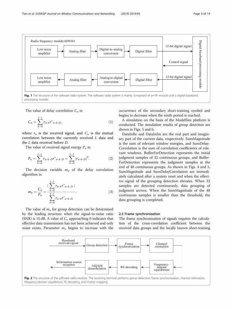
2 Methods2.1 Structure of software radio systemThe software radio system is mainly composed of RFmodule and digital baseband processing module. TheRF module converts RF analog signals to basebanddigital signals and vice versa, and it facilitates RF re-ceiving and transmitting. The communication proto-col in the physical layer is realized by the digitalbaseband processing module, which ensured signalencoding/decoding, and facilitated modulation and de-modulation [13]. The structure of the software radiosystem is shown in Fig. 1.
2.2 Implementation of software radio receiving terminalThe receiving terminal of the software radio performsgroup detection, frame synchronization, channel esti-mation, frequency-domain equilibrium, RS decoding,inverse mapping, and so on. In the main signal pro-cessing of the digital baseband receiving module, thefirst step is to conduct group detection, followed bysignal synchronization and channel estimation basedon training sequences. Then, signals are balanced onthe basis of data from channel estimation to compen-sate for the frequency-selective fading of signalscaused by multipath transmission. Finally, RS decod-ing and 16QAM demodulation are accomplished. Thestructure of the software radio receiver is shown inFig. 2.
2.3 The structure of AD9361AD9361 is composed of the 2 × 2 transceiver, the con-figuration interface of Serial Peripheral Interface (SPI),the AUXADC, internal PLLs, the programmable GPO,and the data bus of 2 × 12 bits which can be config-ured as differential or single terminal. Each transmit-ting and receiving channel of AD9361 is independent.The two receiving channels are composed of low-noise amplifier, mixer, amplifier, filter, and ADC. Thetwo transmitting channels are composed of DAC, fil-ter, amplifier, low-noise amplifier, and mixer. Theconfiguration interface of SPI is compatible with thestandard mode of four lines. The structure ofAD9361 is shown in Fig. 3.
2.4 Group detectionGroup detection is performed by using the leadingstructure. The circuit used for group detection is shownin Fig. 4, which is designed and realized according tothe circuit procedure [14].
Tian et al. EURASIP Journal on Wireless Communications and Networking (2019) 2019:95 Page 2 of 14
The value of delay correlation Cn is:
Cn ¼XL−1k¼0
rn−kr�n−k−D; ð1Þ
where rn is the received signal, and Cn is the mutualcorrelation between the currently received L data andthe L data received before D.The value of received signal energy Pn is:
Pn ¼XL−1k¼0
rn−k−Dr�n−k−D ¼
XL−1k¼0
rn−k−Dj j2: ð2Þ
The decision variable mn of the delay correlationalgorithm is:
mn ¼ Cn
Pn¼
jXL−1k¼0
rn−kr�n−k−D j
XL−1k¼0
rn−kr�n−k−D
: ð3Þ
The value of mn for group detection can be determinedby the leading structure when the signal-to-noise ratio(SNR) is 15 dB. A value of Cn approaching 0 indicates thateffective data transmission has not been achieved and onlynoise exists. Parameter mn begins to increase with the
occurrence of the secondary short-training symbol andbegins to decrease when the ninth period is reached.A simulation on the basis of the ModelSim platform is
conducted. The simulation results of group detection areshown in Figs. 5 and 6.DataInRe and DataInIm are the real part and imagin-
ary part of the current data, respectively. SumMagnitudeis the sum of relevant window energies, and SumDelay-Correlation is the sum of correlation coefficients of rele-vant windows. BufferForDetection represents the initialjudgment samples of 32 continuous groups, and Buffer-ForDetection represents the judgment samples at theend of 48 continuous groups. As shown in Figs. 4 and 5,SumMagnitude and SumDelayCorrelation are immedi-ately calculated after a system reset and when the effect-ive signal of the grouping detection elevates. When 32samples are detected continuously, data grouping ofjudgment arrives. When the SumMagnitude of the 48continuous samples is smaller than the threshold, thedata grouping is completed.
2.5 Frame synchronizationThe frame synchronization of signals requires the calcula-tion of the cross-correlation coefficient between thereceived data groups and the locally known short-training
Fig. 1 The structure of the software radio system. The software radio system is mainly composed of an RF module and a digital basebandprocessing module
Fig. 2 The structure of the software radio receiver. The receiving terminal performs group detection, frame synchronization, channel estimation,frequency-domain equilibrium, RS decoding, and inverse mapping
Tian et al. EURASIP Journal on Wireless Communications and Networking (2019) 2019:95 Page 3 of 14

Fig. 3 The structure of AD9361. The whole circuit of RF and IF signals is integrated into one chip by adopting zero-IF architecture, which is composed ofthe transceiver, the configuration interface of SPI, the AUXADC, the internal PLLs, the programmable GPO, and the data bus
Fig. 4 Circuit procedure for group detection. Group detection is performed by using the leading structure. Cn is the mutual correlation between thecurrently received L data and the L data received before D. Pn is the value of received signal energy. mn is the decision variable of the delaycorrelation algorithm
Tian et al. EURASIP Journal on Wireless Communications and Networking (2019) 2019:95 Page 4 of 14

symbols [15]. Cross-correlation coefficient Ck can beexpressed as:
Ck ¼XD−1m¼0
rk−m � S�m; ð4Þ
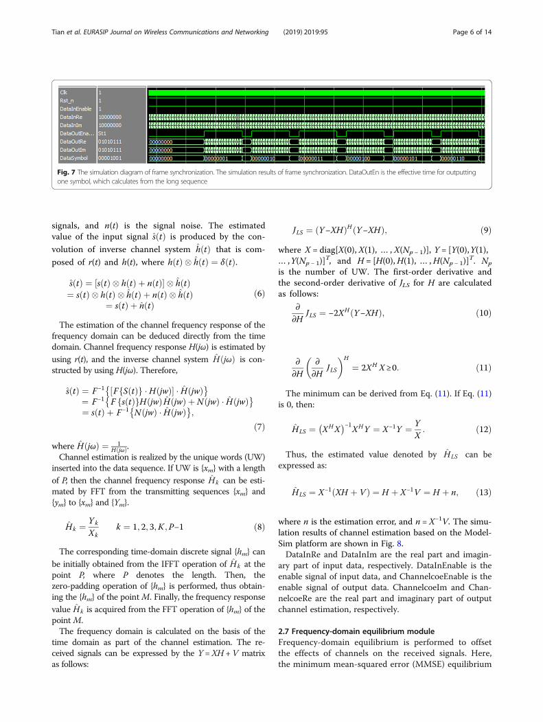
where the superscript ∗ is a conjugation, and D is the lengthof the cross-correlation coefficient, which is determined tobe 16. The positions of the short-training symbols arejudged according to the value of ∣Ck∣. The moment of thelast peak of ∣Ck∣ is designated as the end point of theshort-training symbols.The simulation results of frame synchronization
based on the ModelSim platform are shown in Fig. 7.DataInRe and DataInIm are the real part and imaginary
part of input data, respectively. DataInEnable is the enablesignal of input data, and PCouter is the number of de-tected peaks. First, quantization is implemented when thedata to be synchronized arrives. Then, the correlation iscalculated on the basis of the 16 local short-training
symbols, and the moment at the ninth peak is viewed asthe end point of the short-training symbols. Finally, long-training symbols and data symbols are designated withserial output according to the output format with the cyc-lic prefix eliminated at the same time. As shown in Fig. 7,DataOutEn is the effective time for outputting one symboldenoted as 1 and 2 successively which calculates from thelong-sequence, with the data symbols started from 3. Thisscheme is viewed as one cycle of output data.
2.6 Channel estimationChannel estimation is first performed to estimate the receivedsignals from the time domain, according to which the estima-tion of frequency domain can be easily obtained [16]. Then,the received signals of the estimator can be expressed as:
r tð Þ ¼ s tð Þ � h tð Þ þ n tð Þ; ð5Þ
where h(t) is the impulse response, r(t) represents thereceived signals, s(t) denotes the theoretically received
Fig. 5 The simulation diagram 1 of group detection. The value of mn for group detection can be determined by the leading structure when thesignal-to-noise ratio (SNR) is 15 dB
Fig. 6 The simulation diagram 2 of group detection. The value ofmn for group detection can be determined by the leading structure when the SNR is 15 dB
Tian et al. EURASIP Journal on Wireless Communications and Networking (2019) 2019:95 Page 5 of 14
signals, and n(t) is the signal noise. The estimatedvalue of the input signal sðtÞ is produced by the con-
volution of inverse channel system hðtÞ that is com-
posed of r(t) and h(t), where hðtÞ � hðtÞ ¼ δðtÞ.
s tð Þ ¼ s tð Þ � h tð Þ þ n tð Þ½ � � h tð Þ¼ s tð Þ � h tð Þ � h tð Þ þ n tð Þ � h tð Þ
¼ s tð Þ þ n tð Þð6Þ
The estimation of the channel frequency response of thefrequency domain can be deduced directly from the timedomain. Channel frequency response H(jω) is estimated byusing r(t), and the inverse channel system HðjωÞ is con-structed by using H(jω). Therefore,
s tð Þ ¼ F−1 F S tð Þf g � H jwð Þ½ � � H jwð Þ� �¼ F−1 F s tð Þf gH jwð Þ H jwð Þ þ N jwð Þ � H jwð Þ� �¼ s tð Þ þ F−1 N jwð Þ � H jwð Þ� �
;
ð7Þwhere HðjωÞ ¼ 1
HðjωÞ.Channel estimation is realized by the unique words (UW)
inserted into the data sequence. If UW is {xm} with a lengthof P, then the channel frequency response Hk can be esti-mated by FFT from the transmitting sequences {xm} and{ym} to {xm} and {Ym}.
Hk ¼ Yk
Xkk ¼ 1; 2; 3;K ;P−1 ð8Þ
The corresponding time-domain discrete signal {hm} canbe initially obtained from the IFFT operation of Hk at thepoint P, where P denotes the length. Then, thezero-padding operation of {hm} is performed, thus obtain-ing the {hm} of the pointM. Finally, the frequency responsevalue Hk is acquired from the FFT operation of {hm} of thepoint M.The frequency domain is calculated on the basis of the
time domain as part of the channel estimation. The re-ceived signals can be expressed by the Y =XH +V matrixas follows:
JLS ¼ Y−XHð ÞH Y−XHð Þ; ð9Þ
where X = diag[X(0), X(1), … , X(Np − 1)], Y = [Y(0),Y(1),… ,Y(Np − 1)]
T, and H = [H(0),H(1), … ,H(Np − 1)]T. Np
is the number of UW. The first-order derivative andthe second-order derivative of JLS for H are calculatedas follows:
∂∂H
JLS ¼ −2XH Y−XHð Þ; ð10Þ
∂∂H
∂∂H
JLS
� �H
¼ 2XH X ≥0: ð11Þ
The minimum can be derived from Eq. (11). If Eq. (11)is 0, then:
HLS ¼ XHX� �−1
XHY ¼ X−1Y ¼ YX: ð12Þ
Thus, the estimated value denoted by HLS can beexpressed as:
HLS ¼ X−1 XH þ Vð Þ ¼ H þ X−1V ¼ H þ n; ð13Þ
where n is the estimation error, and n = X−1V. The simu-lation results of channel estimation based on the Model-Sim platform are shown in Fig. 8.DataInRe and DataInIm are the real part and imagin-
ary part of input data, respectively. DataInEnable is theenable signal of input data, and ChannelcoeEnable is theenable signal of output data. ChannelcoeIm and Chan-nelcoeRe are the real part and imaginary part of outputchannel estimation, respectively.
2.7 Frequency-domain equilibrium moduleFrequency-domain equilibrium is performed to offsetthe effects of channels on the received signals. Here,the minimum mean-squared error (MMSE) equilibrium
Fig. 7 The simulation diagram of frame synchronization. The simulation results of frame synchronization. DataOutEn is the effective time for outputtingone symbol, which calculates from the long sequence
Tian et al. EURASIP Journal on Wireless Communications and Networking (2019) 2019:95 Page 6 of 14

algorithm is applied as the frequency-domain equilib-rium [17].Suppose that the set of transmitting data is denoted
by s (s = [s0, s1, … , sN − 1]T), N is the number of FFT
points (h = [h0, … , hL − 1.0, … , 0]T), and L is the lengthof impulse response. Then, the received signal vectoris r = [r0, r1, … , rN − 1]
T. Accordingly,
r ¼ h� sþ v ð14Þ
where ⊗ is the cyclic convolution, and v = [v0, v1, … ,vN − 1]
T is the channel noise. On the basis of the FFT ofEq. (14),
Rk ¼ SkHk þ Vk ; ð15Þ
where Hk ¼PL−1
m¼0ðhme− j2πkm=NÞ , and Rk, Sk, Hk, andVk are the frequency domain values of received sig-nals, transmitting signals and channel impulse re-sponse function, and additive white Gaussian noise.If the equilibrium coefficient is Wk, then the frequency-
domain output after equilibrium is:
~Sk ¼ WkHkSk þWkVk : ð16Þ
According to its definition, the mean square error(MSE) after the equilibrium can be deduced.
MSE ¼ EXN−1
k¼0
j ~Sk−Sk j
¼ EXN−1
k¼0
WkHk−1½ �Sk þWkVkj j2
¼XN−1
k¼0
E WkHk−1½ �Sk þWkVkj j2
¼XN−1
k¼0
Fk
: ð17Þ
Suppose that σ2N is the noise power on the frequencydomain and σ2S is the signal power on the frequency do-main, then:
σ2N ¼ E Vkj j2; ð18Þ
σ2S ¼ E Skj j2: ð19ÞOn the basis of Eq. (18) and Eq. (19), the following
can be derived:
Fk ¼ WkHk−1j j2σ2S þ Wkj j2σ2N : ð20Þ
If argz1 = arg z2, |z1 − z2|≥|| z1| − | z2| |(z1, z2 ∈W) istrue, then:
Fk ≥ WkHk−1j j2σ2N ¼ WkHkj j−1ð Þ2σ2S
þ Wkj j2σ2N ; ð21Þwhere Fk uses the lower limit value based on the condi-tion of argWkHk = arg 1 = 0.
argWk ¼ − argHk ð22ÞIf the lower limit of Fk is y, then the minimum y
should be calculated, such that:
y ¼ WkHkj j−1ð Þ2σ2S þ Wkj j2σ2N¼ H2
kσ2S−σ
2N
�� �� Wkj j2−2Hkσ2S Wkj j2 þ σ2S: ð23Þ
To derive the minimum of y:
Wk ¼ H�σ2SHkj j2σ2
S þ σ2N¼ H�
Hkj j2 þ σ2S
σ2N
: ð24Þ
Given that σ2Sσ2N
¼ SNR , the MMSE equilibrium coeffi-
cient can be expressed as Wk ¼ H�k
jHk j2þ1=SNR. In Eq. (24),
0 ≤ k ≤N − 1 and SNR denotes the signal-to-noise ratioof the transmitting terminal.The simulation of signals based on the MMSE algo-
rithm is conducted in Matlab. The following parametersare included:Multipath channel: the corresponding power of the
SUI.3 channel model is [0, − 5, − 10 dB];Modulation mode: 16QAM;
Fig. 8 The simulation diagram of channel estimation. The simulation results of channel estimation. The frequency domain is calculated on the basis ofthe time domain as part of the channel estimation
Tian et al. EURASIP Journal on Wireless Communications and Networking (2019) 2019:95 Page 7 of 14

SC-FDE system parameters: UW uses the Chu se-quence, and the length is N = 64;M = 256, and the MMSE equilibrium algorithm is
used.The hardware implementation block diagram of
channel equalization module based on FPGA is shownin Fig. 9.SC-FDE symbols in the time domain are read from
“buffer of RX frame sample” by the channel equalizationmodule and sent to the FFT module to calculate the fre-quency domain values of SC-FDE symbols.Frequency domain values are read from “buffer of
CSI” by the CSI_ACQ module, which can complete theintegration of corresponding samples meanwhile.With the complex multiplication of the corresponding
sample points completed by the FDE_CORE module, thefrequency domain equalization is achieved.Meanwhile, with the subsequent IFFT_256 module
controlled by the FDE_CORE module, the sample pointsin the frequency domain after the equilibration are re-stored to the time domain and stored in the symbol buf-fer of SIG domain and the time buffer of DATA domain,respectively.The simulation results of the channel equilibrium
based on the ModelSim platform are shown in Fig. 10.DataInRe and DataInIm are the real part and imaginary
part of the input data, respectively. DataInEnable is theenable signal of input data. DataOutRe and DataOutIm arethe real part and imaginary part of output data,respectively.
2.8 RS decodingThe design procedures of the RS decoder are as follows:
1. The adjoint polynomial s(x) of RS codes iscalculated from the receiving codes.
2. The error position polynomial a(x) and error valuepolynomial δ(x) are solved by an adjointpolynomial.
3. The error position can be acquired by using theChien searching method to calculate the roots oferror location polynomials.
4. The error magnitude corresponding to each errorlocation can be obtained from the error valuepolynomial by using the Fomey algorithm, namelyC(x) = R(x) − E(x).
5. After decoding, the adjoint formula of thecodeword is calculated again, and the adjointformula is determined by detecting whether theadjoint formula is zero or not.
According to the above procedures, RS decoder shouldinclude four parts: the adjoint polynomial calculationmodule, the key equation solving module, the moneysearch module, and the Fomey algorithm module [18].Specific procedures of RS decoding design are as
follows:1. Solving the adjoint polynomial of RS decoding. The
parameters of RS (255,191) are as follows:Encoding length: n = 255Information bit length: k = 191Parity bit length: 64Error correcting capability: t = 32Primitive polynomial:
p xð Þ ¼ x8 þ x4 þ x3 þ x2 þ x1 þ 1: ð25Þ
The generating polynomial of RS (255,191) is as follows:
Fig. 9 The hardware implementation block diagram of channel equalization module. The hardware implementation block diagram of channelequalization module. SC-FDE symbols in the time domain are read from “buffer of RX frame sample” by the channel equalization module and sent tothe FFT module to calculate the frequency domain values of SC-FDE symbols. Frequency domain values are read from “buffer of CSI” by the CSI_ACQmodule, which can complete the integration of corresponding samples meanwhile. With the complex multiplication of the corresponding samplepoints completed by the FDE_CORE module, the frequency domain equalization is achieved
Tian et al. EURASIP Journal on Wireless Communications and Networking (2019) 2019:95 Page 8 of 14

g xð Þ ¼ x−a0� �
x−a1� �
x−a2� �
Λ x−a15� �
: ð26Þ
The RS is solved by using a, a2, a3,… , a32, inwhich R(x) = r0 + r1x + r2x
2 + … rn − 1a(n − 1). The 32 ad-
joint expressions of RS (255,191) codes are acquired,namely s1, s2, s3,… , s32.
s xð Þ ¼X2ti¼1
sixi−1; si ¼ R ai
� �; 1≤ i≤2tð Þsi
¼ R ai� � ð27Þ
2. Solving the error position polynomial. Firstly, theerror location polynomial δ(x) is obtained, then theerror location polynomial and the error value polyno-mial are obtained. The error location polynomial δ(x)can be defined as:
δ xð Þ ¼ 1−θ1xð Þ 1−θ2xð ÞΛ 1−θtxð Þ: ð28Þ
The error location is θ1.… θt. The right part of the ex-pansion equation is simplified as follows:
δ xð Þ ¼ 1þ θ1 þ θ2 þ Λþ θtð Þxþ θ1θ2 þ θ1θ3 þ Λþ θt−1θtð Þx2 þ Λþ θ1θ2Λþ θ1Þxt : ð29Þ
The error location polynomial is acquired:
δ xð Þ ¼ 1þ δ1xþ δ1x2 þ Λþ δ1xt : ð30Þ
3. Solving the error position. The error location ofreceiving polynomial R(x) = r0 + r1x +Λ + rn − 2x
n − 2 + rn− 1x
n − 1 is acquired according to the root of δ1x.4. Ascertaining the error pattern E(x) and the polyno-
mial of c(x). The error value polynomial is defined asfollows: ω(x) = S(x)δ(x), which is simplified as follows:
ω xð Þ ¼ s1xþ s2 þ δ1s1ð Þx2 þ Λþ st þ δ1st−1 þ Λþ δt−1s1ð Þxtþ stþ1 þ δts1 þ Λþ δ1s1ð Þxtþ1 þ Λ: ð31Þ
The following equations can be verified.
st¼1 þ δ1st þ Λþ δts1 ¼ 0
stþ2 þ δ1st þ Λþ δts2 ¼ 0
s2t þ δ1s2tþ1 þ Λþ δtst ¼ 0 ð32Þ
The error value polynomial ω(x) =ω1x+ω2x2 +ωtx
t can beobtained if ω1 = s1, ω2 = s2 + δ1s1, Λ, ωt= st+ δ1st− 1 +Λδt−1s1. The error pattern EðxÞ ¼ Pt
i¼1 Y ixtii can be obtained by
Y j ¼ −x jωðx−1j Þδðx−1j Þ
. Here, xj is the root of the Chien searching
method. The final actual code C(x) is obtained with E(x) andthe receiving code R(x) superposed.
Fig. 11 The simulation diagram 1 of the RS decoder. The output data of the decoders. The decoding results are shown
Fig. 10 The simulation results of channel equilibrium. The simulation results of channel equilibrium. Frequency-domain equilibrium is performed to offsetthe effects of channels on the received signals. And the MMSE equilibrium algorithm is applied as the frequency-domain equilibrium
Tian et al. EURASIP Journal on Wireless Communications and Networking (2019) 2019:95 Page 9 of 14
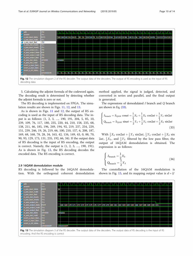
5. Calculating the adjoint formula of the codeword again.The decoding result is determined by detecting whetherthe adjoint formula is zero or not.The RS decoding is implemented on FPGA. The simu-
lation results are shown in Figs. 11, 12, and 13.As is shown in Figs. 11 and 12, the output of RS en-
coding is used as the input of RS decoding data. The in-put is as follows: (1, 2, 3, …, 190, 191, 204, 5, 85, 10,239, 109, 76, 117, 180, 235, 220, 44, 210, 158, 235, 68,138, 211, 46, 185, 196, 249, 194, 92, 219, 237, 254, 229,151, 239, 246, 19, 26, 219, 66, 100, 210, 157, 6, 208, 187,169, 68, 168, 78, 28, 34, 163, 42, 134, 149, 43, 0, 88, 70,90, 93, 129, 173, 131, 235, 192, 66, 34). If the output dataof RS decoding is the input of RS encoding, the outputis correct. Namely, the output is (1, 2, 3, …, 190, 191).As is shown in Fig. 13, the RS decoding decodes theencoded data. The RS encoding is correct.
2.9 16QAM demodulation moduleRS decoding is followed by the 16QAM demodula-tion. With the orthogonal coherent demodulation
method applied, the signal is judged, detected, andconverted in series and parallel, and the final outputis generated.The expressions of demodulated I branch and Q branch
are shown in Eq. (33).
Ibranch ¼ SQAM cosat ¼ 12Xk þ 1
2Xk cos2at þ 1
2Yk sin2at
Qbranch ¼ SQAM sinat ¼ 12Y k þ 1
2Yk cos2at þ 1
2Xk sin2at
8><>:
ð33Þ
With 12Xk cos2at þ 1
2Yk sin2at, 12Yk cos2at þ 1
2Xk sin2at , 1
2Xk , and 12Yk filtered by the low pass filter, the
output of 16QAM demodulation is obtained. Theexpression is as follows:
Ibranch ¼ 12Xk
Qbranch ¼ 12Yk
8><>: ð34Þ
The constellation of the 16QAM modulation isshown in Fig. 15, and its mapping output value is d = (I
Fig. 12 The simulation diagram 2 of the RS decoder. The output data of the decoders. The output of RS encoding is used as the input of RSdecoding data
Fig. 13 The simulation diagram 3 of the RS decoder. The output data of the decoders. The output data of RS decoding is the input of RSencoding. And the RS encoding is correct
Tian et al. EURASIP Journal on Wireless Communications and Networking (2019) 2019:95 Page 10 of 14

+ jQ) × KMOD, where KMOD ¼ 1=ffiffiffiffiffi10
p. The constellation
of the 16QAM modulation is shown in Fig. 14.The I-way component and Q-way component cor-
respond to b0 b1 and b2 b3 in the code elementsb0 b1 b2 b3, respectively. With the decisionthresholds set as −2 × KMOD, 0 and 2 × KMOD, respect-ively, the I and Q can be demodulated now.
3 Experiment results and discussionWith the AD9361 used as the RF module, ZC706 ap-plied as the digital baseband processing module of SOC,
and ZC706 utilized as the ARM+FPGA framework, thehardware platform of the software radio system is built.The physical connection between AD9361 and ZC706 isshown in Fig. 15. The AD9361 board card and theZYNQ ZC706 development board are connected byFMC. A spectrum analyzer is used as the tester of thetransmitting and receiving terminals during the systemtest. The accuracy of the system test is evaluated by ob-serving the frequency spectra.Joint testing is performed for the designed software
radio receiver, which is based on the hardware platformof AD9361. The test framework of the receiving terminal
Fig. 14 The constellation of the 16QAM modulation. The I-way component and Q-way component correspond to b0 b1 and b2 b3 in the codeelements b0 b1 b2 b3, respectively
Fig. 15 The physical connection between AD9361 and ZC706. The AD9361 board card and the ZYNQ ZC706 development board are connectedby FMC
Tian et al. EURASIP Journal on Wireless Communications and Networking (2019) 2019:95 Page 11 of 14

is shown in Fig. 16. The transmitting central frequency,transmit gain, and bandwidth are 1.435 GHz, 15 dB, and20MHz, respectively. AD9361 is connected to ZYNQvia FMC, and ZYNQ is connected to the spectrumanalyzer via JTAG. The final results are displayedthrough the spectrum analyzer. The detailed procedurecan be described as follows: signals are received, signalsare inputted into AD9361 via the antenna, and these in-put signals are sent into the digital baseband processingmodule to complete the processing after amplification,mixing, filtering, and A/D conversion based on AD9361.AD9361 is set as the working modes of 1R1T, LVDS,
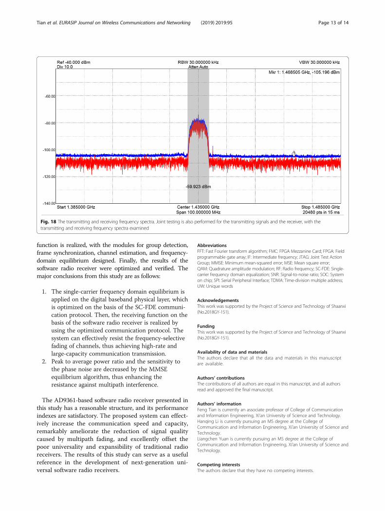
and TDD. The ADC frequency is set as 13MHz, and thelocal frequency is set as 1.435 GHz, which can be dis-played through the spectrum analyzer. The frequencyspectra at the receiving terminal are shown in Fig. 17.Joint testing is also performed for the transmitting sig-
nals and the receiver, with the transmitting and receivingfrequency spectra examined, which are shown in Fig. 18.
As shown in Fig. 16, the transmitting frequencyspectrum is located in the upper position, while the re-ceiver frequency spectrum is located in the lower position.The overlapping of the frequency spectra of the transmit-ting signals and receiver indicates the consistency of pa-rameters between the transmitting and receiving signals.Therefore, transmitting signals are received accurately.In this study, a joint experiment of RF module and
digital baseband processing module is carried out. Theexperiment is carried out by two modules combinedwith a signal source and a spectrum analyzer. But thereis no video display part and signal compression part,which can be added to the system to promote the appli-cations in our future research.
4 ConclusionsAn AD9361-based software radio system was designed byusing AD9361 as the hardware platform. The receiving
Fig. 16 The test framework of the receiving terminal. The test framework of the receiving terminal. Joint testing is performed for the designedsoftware radio receiver, which is based on the hardware platform of AD9361
Fig. 17 The frequency spectra at the receiving terminal. AD9361 is set as the working modes of 1R1T, LVDS, and TDD. The ADC frequency is setas 13 MHz, and the local frequency is set as 1.435GHz
Tian et al. EURASIP Journal on Wireless Communications and Networking (2019) 2019:95 Page 12 of 14
function is realized, with the modules for group detection,frame synchronization, channel estimation, and frequency-domain equilibrium designed. Finally, the results of thesoftware radio receiver were optimized and verified. Themajor conclusions from this study are as follows:
1. The single-carrier frequency domain equilibrium isapplied on the digital baseband physical layer, whichis optimized on the basis of the SC-FDE communi-cation protocol. Then, the receiving function on thebasis of the software radio receiver is realized byusing the optimized communication protocol. Thesystem can effectively resist the frequency-selectivefading of channels, thus achieving high-rate andlarge-capacity communication transmission.
2. Peak to average power ratio and the sensitivity tothe phase noise are decreased by the MMSEequilibrium algorithm, thus enhancing theresistance against multipath interference.
The AD9361-based software radio receiver presented inthis study has a reasonable structure, and its performanceindexes are satisfactory. The proposed system can effect-ively increase the communication speed and capacity,remarkably ameliorate the reduction of signal qualitycaused by multipath fading, and excellently offset thepoor universality and expansibility of traditional radioreceivers. The results of this study can serve as a usefulreference in the development of next-generation uni-versal software radio receivers.
AbbreviationsFFT: Fast Fourier transform algorithm; FMC: FPGA Mezzanine Card; FPGA: Fieldprogrammable gate array; IF: Intermediate frequency; JTAG: Joint Test ActionGroup; MMSE: Minimum mean-squared error; MSE: Mean square error;QAM: Quadrature amplitude modulation; RF: Radio frequency; SC-FDE: Single-carrier frequency domain equalization; SNR: Signal-to-noise ratio; SOC: Systemon chip; SPI: Serial Peripheral Interface; TDMA: Time-division multiple address;UW: Unique words
AcknowledgementsThis work was supported by the Project of Science and Technology of Shaanxi(No.2018GY-151).
FundingThis work was supported by the Project of Science and Technology of Shaanxi(No.2018GY-151).
Availability of data and materialsThe authors declare that all the data and materials in this manuscriptare available.
Authors’ contributionsThe contributions of all authors are equal in this manuscript, and all authorsread and approved the final manuscript.
Authors’ informationFeng Tian is currently an associate professor of College of Communicationand Information Engineering, Xi’an University of Science and Technology.Hanqing Li is currently pursuing an MS degree at the College ofCommunication and Information Engineering, Xi’an University of Science andTechnology.Liangchen Yuan is currently pursuing an MS degree at the College ofCommunication and Information Engineering, Xi’an University of Science andTechnology.
Competing interestsThe authors declare that they have no competing interests.
Fig. 18 The transmitting and receiving frequency spectra. Joint testing is also performed for the transmitting signals and the receiver, with thetransmitting and receiving frequency spectra examined
Tian et al. EURASIP Journal on Wireless Communications and Networking (2019) 2019:95 Page 13 of 14

Publisher’s NoteSpringer Nature remains neutral with regard to jurisdictional claims in publishedmaps and institutional affiliations.
Received: 14 January 2019 Accepted: 28 March 2019
References1. C. Andrews, A passive mixer-first receiver with digitally controlled and
widely tunable RF interface. IEEE J. Solid State Circuits 45(12), 2696–2708(2010). https://doi.org/10.1109/JSSC.2010.2077151
2. H. Darabi, D. Murphy, M. Mikhemar, H. Wu, 2.1 A Highly Linear Inductor LessWideband Receiver with Phase- and Thermal-Noise Cancellation (IEEEInternational Solid-State Circuits Conference, San Francisco, 2015), pp. 1–3.https://doi.org/10.1109/ISSCC.2015.7062850
3. L. Yang, Z. Zhang, W. Hou, B. Zhao, H. Zheng, Papyrus: a software platformfor distributed dynamic spectrum sharing using SDRs. ACM SIGCOMMComputer Communication Review 41(1), 32–37 (2017). https://doi.org/10.1145/1925861.1925866
4. C.J. Loubser, T.G. Swart, Cognitive Radio DAB MAC Protocol Performance Usinga CR Specific Simulator and Software Defined Radio (IEEE AFRICON, CapeTown, 2017), pp. 139–144. https://doi.org/10.1109/AFRCON.2017.8095470
5. A. Kamaleldin, S. Hosny, K. Mohamed, M. Gamal, A. Hussien, E. Elnader, A.Shalash, A.M. Obeid, Y. Ismail, H. Mostafa, A Reconfigurable HardwarePlatform Implementation for Software Defined Radio Using Dynamic PartialReconfiguration on Xilinx Zynq FPGA (2017 IEEE 60th International MidwestSymposium on Circuits and Systems (MWSCAS), Boston, 2017), pp. 1540–1543. https://doi.org/10.1109/MWSCAS.2017.8053229
6. A. Marwanto, S.K.S. Yusof, M.H. Satria, Orthogonal frequency-divisionmultiplexing-based cooperative spectrum sensing for cognitive radionetworks. Telkomnika (Telecomm Comput Electron Contr) 12(1), 143–152(2014). https://doi.org/10.12928/TELKOMNIKA.v12i1.310
7. R. Srinivasa, S. Kotha, S. Kumar, An approach for fixed coefficient RNS-based FIRfilter. Int. J. Electron., 1–19 (2017). https://doi.org/10.1080/00207217.2017.1296593
8. X. Qin, L. Wang, H. Zhao, Y. Deng, Realization of spectrum sensing based onMATLAB and general software radio peripherals. Comput. Eng. 41(5), 106–110 (2015)
9. S. Xu, Z. Yu, K. Chang, Y. Wu, B. L, Design and implementation of faultprediction software for airborne software radio system. Meas Contr Technol35(8), 111–114 (2016). https://doi.org/10.3969/j.issn.1000-8829.2016.08.028
10. Z. Cui, Design of frequency hopping communication terminal based onsoftware radio principle. Modern Navigation 8(5), 365–371 (2017)
11. Y. Zhang, X. Cui, T. Da, G. Wang, Design of GNSS jamming and multipathmonitoring system based on software radio. Telecommun. Eng. 57(3), 288–295 (2017)
12. Z. Yin, L. Cheng, Design of low power software radio platform based onZYNQ7000. Wireless Internet Technol 37(3), 31–32 (2018)
13. M. Mishra, A. Potnis, P. Dwivedy, S.K. Meena, Software Defined Radio BasedReceivers Using RTL — SDR: a Review (2017 International Conference onRecent Innovations in Signal processing and Embedded Systems (RISE),Bhopal, 2017), pp. 62–65. https://doi.org/10.1109/RISE.2017.8378125
14. Y. Qi, X. Chen, Z. Xie, S. Yuan, An Improved MMSE-RISIC EqualizationAlgorithm Based on STBC-SC-FDE (2018 IEEE 3rd International Conference onSignal and Image Processing (ICSIP), Shenzhen, 2018), pp. 310–314. https://doi.org/10.1109/SIPROCESS.2018.8600476
15. K. Kumar, S. Pillai, S. Sagar, S.K. Parambeth, N. Prem Krishnan, Implementationof Digital Pre-Distortion for Power Amplifier Linearisation in Software DefinedRadio (Twenty-third National Conference on Communications (NCC),Chennai, 2017), pp. 1–6
16. J. David Cepeda, S.I. Rodríguez, M. Rico-Martínez, C. Daniel Muñoz, M. Varón,I.T. Monroy, Performance Evaluation of a Real Time OFDM Radio over FiberSystem at 2.5 GHz Using Software Defined Radio SDR (SBMO. IEEE MTT-SInternational Microwave and Optoelectronics Conference (IMOC), 2017), pp.1–5. https://doi.org/10.1109/IMOC.2017.8121094
17. E. Balevi, A.Ö. Yιlmaz, Analysis of frequency domain oversampled MMSE SC-FDE. IEEE Commun. Lett. 20(2), 232–235 (2016)
18. W. Lu, Y. Liang, Y. Liu, Z. Liang, W. Zhang, The design of an RS decoderbased on the mCS-RiBM algorithm for 100 Gb/s optical communicationsystems. IEEE Trans Circuits Syst Express Briefs 66(1), 76–80 (2019)
Tian et al. EURASIP Journal on Wireless Communications and Networking (2019) 2019:95 Page 14 of 14