Design and Implementation of a Smart Home System · The goal of the project was to implement a...
60
Subash Luitel Design and Implementation of a Smart Home System Helsinki Metropolia University of Applied Sciences Bachelor of Engineering Information Technology Bachelor’s Thesis 29 August 2013
Transcript of Design and Implementation of a Smart Home System · The goal of the project was to implement a...

Subash Luitel
Design and Implementation of a Smart Home System
Helsinki Metropolia University of Applied Sciences
Bachelor of Engineering
Information Technology
Bachelor’s Thesis
29 August 2013

Abstract
Author(s) Title Number of Pages Date
Subash Luitel Design and Implementation of a Smart Home System 46 pages + 1 appendix 29 August 2013
Degree Bachelor of Engineering
Degree Programme Information Technology
Specialisation option Embedded System Engineering
Instructor(s)
Sami Sainio, Project Supervisor
The goal of the project was to implement a smart home by controlling electronic devices at home remotely and to get an alert on intrusion or movement around the restricted prem-ises. The devices were controlled by a mobile phone using the SMS service available and the alerts were also received as an SMS mentioning the activity occuring around the prem-ises. The application consisted of two units, the microcontroller and the mobile unit. The mobile unit acted as a recipient to get responses from the micrcontroller as well as a controller for giving instructions. Different operations were performed based on the given instructions. In addition to this, the microcontroller unit was responsible for reading input from the sensors. The Arduino platform was used as the system platform with Arduino Uno Board as the microcontroller board. The SIM900 GPRS/GSM module was used to communicate be-tween the microcontroller unit and the mobile unit. The system could be installed at any place and could be controlled by any mobile phone supporting the SMS service. The mobile phone neither needs to have any special features nor hardware nor any special application to use the system. The system consists of three sensors which are used as heat detector, intrusion detector and motion detector along with a remotely managed light system. The goal of the project was achieved successfully. However, the system is limited to the availability of the GSM network as the GSM network is responsible for communication be-tween the mobile station and the GPRS module. The project could be extended further by using wireless communication or Internet communication along with the GSM network to reduce the limitation in the absence of GSM network.
Keywords GSM, Arduino, SIM900, AT command, sensor, SMS, LM35, PIR, hall effect, mobile station.

Contents
1 Introduction 1
2 Theoretical Background and Hardware Overview of the System 3
2.1 Arduino Platform 3
2.1.1 Arduino Uno Board 3
2.1.2 ATmega328 Microcontroller 4
2.2 GPRS/GSM Network 7
2.3 Sensor 9
2.3.1 Temperature Sensor 10
2.3.2 Infrared Sensor 14
2.3.3 Magnetic Sensors 17
3 Design and Development of the System 21
3.1 System Design 21
3.2 Interfacing Sim900 GPRS/GSM Module 23
3.3 Interfacing and Implementing Sensors 24
3.3.1 Heat Detector 24
3.3.2 Motion Detector 26
3.3.3 Intrusion Detector 28
3.4 Implementation of remotely managed light system 29
3.5 System development 32
3.6 Testing the system 34
4 Result 38
5 Discussion 42
6 Conclusion 45
References 46
Appendices
Appendix 1. C-language code of the system

List of Abbreviations
ADC – Analog to Digital converter
ALU – Arithmetic Logic Unit
AT – Attention
CMOS – Complementary Metal Oxide Semiconductor
CPU – Central Processing Unit
EEPROM – Electrically Erasable Programmable Read Only Memory
FTDI – Future Technology International
GPRS – General Packet Radio Service
GSM – Global System for Mobile Communication
ICSP – In Circuit Serial Programming
IR – Infrared
MCU – Microcontroller Unit
MISO – Master In Slave Out
MOSI – Master Out Slave In
PWM – Pulse Width Modulation
RISC – Reduced Instruction Set Computer
SCLK – Serial Clock
SIM – Subscriber Identity Module
SMS – Short Messaging Servicing
SMSC – Short Message Service Centre
SPI – Serial Peripheral Interface
SRAM – Static Random Access Memory
SS – Slave Select
USART – Universal Synchronous/Asynchronous Receiver/Transmitter
USB – Universal Serial Bus

1
1 Introduction
Lifestyle in the modern society along with human behaviour and thinking is changing
dramatically with the advancement of technology, and the concept of a simple home is
changing into a smart home. The advancement of technology has increased the safety
and security of people along with their belongings. One of the reasons for the rise of
the smart home is the increasing risk of burglary and robbery and the busy lifestyle.
The busy lifestyle of people is leading to the necessity of controlling the devices at
home remotely and increasing the necessity of keeping surveillance over their homes.
Mobile phones today are not just used to make calls. The use of mobile phones is
changing with the development of technology and they can be used for different pur-
poses. They can be used as clocks, calendars or controllers instead of being used just
as phones. Today smart phones are available in the market with different applications
and hardware which can be implemented without any further development or en-
hancement. With the help of the GSM network, a mobile can be used to implement a
smart home by controlling devices and getting alerts on robbery and burglary.
There are different types of built smart home systems in the market, and they do not
have flexibility over choosing the types and number of sensors used and the cost of the
system. These systems are prebuilt devices with a limited number of sensors, with a
limited area of coverage and with a limited capacity to control the electronic devices.
Therefore the idea of a smart home system was proposed, to overcome the limitations
of the systems already available in the market. The user can choose the number of
sensors, types of sensors, the area of coverage of the systems along with the number
and types of electronic devices to be controlled. The cost of the system can be deter-
mined by the user as the cost depends on the hardware used in the system chosen by
the developer.
The goal of the project is to implement a smart home system by controlling the elec-
tronic devices at home remotely with the help of a mobile device and getting alerts on
intrusion or movement around the restricted premises. The SIM900-GPRS module and
the Arduino Uno Board are used to communicate between the mobile phone and the
devices and sensors installed at home. The mobile phone can be used as a controller

2
from anywhere in the world if the GSM network is available. The project consists of a
led light which is controlled by the mobile phone to show the demo of controlling
mechanism of the household devices such as light, fan or television. In addition, three
sensors are used as a heat detector, motion detector and intrusion detector which trig-
ger the alarm upon reaching the critical limit. The system is limited to the area with the
GSM network available and the whole system does not work without the network.
3
2 Theoretical Background and Hardware Overview of the System
The system consists of two units: the mobile station and the microcontroller unit with
the SIM900-GPRS module, sensors and the light system. Arduino Uno Board is used
as the microcontroller board. The mobile phone is used as a controller to send instruc-
tions and as a recipient to receive the responses and alerts from the microcontroller
unit, whereas the Arduino Board is the unit responsible for controlling the different parts
and acts as the brain of the system. The SIM900 GSM/GPRS module is responsible for
communication between the microcontroller unit and the mobile station. It is important
to have some idea about the physics and the working principle behind the sensors and
other hardware devices before using it.
2.1 Arduino Platform
Arduino is an open source electronics prototyping platform based on flexible hardware
and software. The arduino is a simple yet sophisticated device which is based on At-
mel’s ATmega microcontrollers. The arduino software is supported by Windows, Macin-
tosh OSX and Linux operating systems despite the fact that most microcontrollers are
limited to Windows operating system. The software language is based on AVR C pro-
gramming language and can be expanded through C++ libraries. There are various
types of arduino microcontroller board available in the market including the arduino kits
and arduino shields. [1]
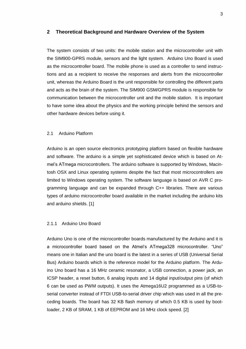
2.1.1 Arduino Uno Board
Arduino Uno is one of the microcontroller boards manufactured by the Arduino and it is
a microcontroller board based on the Atmel’s ATmega328 microcontroller. “Uno”
means one in Italian and the uno board is the latest in a series of USB (Universal Serial
Bus) Arduino boards which is the reference model for the Arduino platform. The Ardu-
ino Uno board has a 16 MHz ceramic resonator, a USB connection, a power jack, an
ICSP header, a reset button, 6 analog inputs and 14 digital input/output pins (of which
6 can be used as PWM outputs). It uses the Atmega16U2 programmed as a USB-to-
serial converter instead of FTDI USB-to-serial driver chip which was used in all the pre-
ceding boards. The board has 32 KB flash memory of which 0.5 KB is used by boot-
loader, 2 KB of SRAM, 1 KB of EEPROM and 16 MHz clock speed. [2]

4
Figure 1: The Arduino Uno Board
Reprinted from the Arduino Board Uno [2]
Figure 1 shows the Arduino Uno Board manufactured by the Arduino in Italy. It can be
powered via a USB connection or with an external power supply. As can be seen in
figure 1, pins A0 to A5 are the analog input pins, pins 0 to 13 are 14 digital input/output
pins and the pins with a “~” sign can be used as the PWM output pins. The digital pins
can be used as input or output pins by selecting the mode by using the function pin-
mode() and then using the function digitalRead() or digitalWrite() according to the ne-
cessity. Pins 0(RX) and 1(TX) are used for serial communication while pins 10(SS),
11(MOSI), 12(MISO) and 13(SCK) are used for SPI (Serial Peripheral Interface) com-
munication. In addition to pin 0 and 1, a SoftwareSerial library allows serial communi-
cation on any of the Uno’s digital pins. [2]
2.1.2 ATmega328 Microcontroller
The microcontroller is a low-power CMOS (Complementary Metal Oxide Semiconduc-
tor) 8-bit microcontroller based on the AVR enhanced RISC (Reduced Instruction Set
Computer) architecture. The powerful execution of instructions in a single clock cycle
leads to the achievement of 1 MIPS per MHz throughputs allowing the designer to op-
timize power consumption versus processing speed. [3]

5
Figure 2: ATmega328 Microcontroller Architecture
Reprinted from Datasheet of ATMega328 [3]
The internal architecture of the microcontroller is shown in figure 2. The central proc-
essing unit (CPU) is the brain of the microcontroller which controls the execution of the
program. The MCU (Microcontroller unit) consists of 4K/8K bytes of in-system pro-
grammable flash with read-while-write capabilities, 256/412/1K bytes EEPROM along
with the 512/1K/2K bytes of SRAM. Along with this, the MCU consists of many other
features: [3]
- 23 general purpose I/O lines and 32 general purpose working registers

6
- 3 flexible timer/counters with compare modes, internal and external interrupts
and a serial programmable USART
- A byte-oriented 2-wire serial interface, an SPI serial port ,a 6-channel 10-bit
ADC (8 channels in TQFP and QFN/MLF packages), a programmable watch-
dog timer with an internal oscillator and 5 software-selectable power saving
modes.[3]
The five, software selectable, power saving modes are Idle mode, Power-down mode,
Power-save mode, ADC Noise Reduction mode and the Standby mode. As mentioned
in section 2.1.2, the CPU is the brain of the microcontroller which controls the execu-
tion of the program. Therefore the CPU is able to access the memories, perform calcu-
lations, control peripherals and handle interrupts. The AVR uses the Harvard architec-
ture – with separate memories and buses for program and data to maximize the per-
formance as well as the parallelism. The principle of execution of instructions in the
program memory is the single-level pipelining. The concept of pre-fetching the next
instruction while executing one instruction enables the instructions to be executed in
every clock cycle and the program memory is in the System Reprogrammable Flash
memory. [3]
Figure 3: Block diagram of the AVR CPU Core architecture
Reprinted from from Datasheet of ATMega328 [3]

7
The block diagram of AVR CPU Core architecture is shown in figure 3. The fast-access
Register File contains 32 x 8 bit general-purpose working registers with a single cycle
access time which results in a single-cycle ALU operation. The arithmetic and logical
operations between the registers or between the constant and a register are supported
by the ALU. The status register is updated to reflect information about the result of the
operation after an arithmetic operation. [3]
The boot program section and the application program section are the two main sec-
tions of the program flash memory. Stack stores the return address of the program
counter during the interrupts and subroutine calls which is allocated in the general data
SRAM. The size of the stack is limited by the total size and usage of the SRAM. The
data SRAM is accessible through five different addressing modes supported in the
AVR architecture while the stack pointer is read/write accessible in the I/O space. The
memory spaces in the AVR architecture are all linear and regular memory maps. [3]
2.2 GPRS/GSM Network
Literally, the GSM stands for Global System for Mobile Communication. The subscrip-
tion and the mobile equipment are separated in the GSM, unlike in analog networks
where the two are not separated. The smart card handling and storing a subscriber’s
data is the SIM (Subscriber Identity Module) card whereas the radio equipment is
called mobile equipment. Hence, the combination of the Subscriber Identity Module
and the mobile equipment is the mobile station. SMS (Short Messaging Service) is one
of the services integrated in the GSM, which provides a means of sending messages of
a limited size to and from the mobile stations. The handling of the SMS is done by the
SMSC (Short Message Service Center) which has to be supported by the GSM net-
work for the transfer of messages between the SMSC and the mobile stations.
[4,212-216]
The GPRS (General Packet Radio Service) is a packet-switched transmission service
supplementing the Circuit Switched data and Short Message Service over the mobile
telephone network [4,229]. The circuit switched network architecture is upgraded to
packet switched network by adding a couple of new infrastructure nodes and making a
software upgrade to the existing network elements. The GPRS is a less costly mobile
data service compared to SMS and Circuit Switched Data and the information is trans-
mitted more quickly, immediately and efficiently across the mobile network. Several

8
new applications are supported by the GPRS which have not been previously sup-
ported over the GSM networks due to the limitations in speed of Circuit Switched Data
(9.6 kbps) and the length of the SMS (160 characters). The information to be transmit-
ted is split into separate but related packets and is reassembled at the receiving end in
the GPRS. [5]
SIM900 GSM/GPRS Module
SIM900 is an ultra-compact and reliable wireless SMT (Surface Mount Technology)
type quad-band GSM/GPRS module designed with a powerful single-chip processor
integrating AMR926EJ-S core manufactured by SIMCom Wireless Solutions Ltd. It de-
livers GSM/GPRS 850/900/1800/1900 MHz performance for voice, SMS and data. It is
a low-power consumption module with current consumption as low as 1.0 mA in sleep
mode. It is optimized for voice and other forms of data transfer including text and im-
ages. The module is 24 mm x 24 mm x 3 mm and is designed to meet any require-
ments for M2M applications. It has a GPRS multi-slot class 10/8 and a B-type GPRS
mobile station class. It is compliant with GSM phase 2/2+, Class 4 (2W@850/900 MHz)
and Class 1 (1W@1800/1900 MHz). AT commands are used to interface and control
the GSM/GPRS module. [6]
AT is the abbreviation of attention and AT commands are instructions used to control
and interface the modem. Despite the fact that every command line starts with “AT”, it
is not a part of the command name but is just the prefix informing the modem about the
start of a command line. For example, D is the actual command name in ATD (Dial)
and +CMGR is the actual command name in AT+CMGR (Read SMS Messages). Basi-
cally, there are two types of AT commands and they are basic commands and ex-
tended commands. The AT commands starting with “+” are extended commands and
almost all of the GSM AT commands are extended commands. For example, +CMGR
(Read SMS Messages), +CMGL (List SMS Messages) and +CMGS (Send SMS Mes-
sages) are extended commands. Similarly, the AT commands that do not start with the
“+” are basic commands. For example, H (Hook Control), A (Answer), D (Dial) and O
(Return to online data state) are basic commands. [7]
The AT commands have a specific syntax and the syntax rules are described below:
1. The commands must start with “AT” and end with a carriage return.

9
2. The first command name should be prefixed with “AT” in a command line con-
taining more than one AT command and the command names should be
separated with semicolons. For example, the name of the manufacturer and
the model number can be found by using the single command line,
AT + CGMI ; +CGMM<CR>
3. The string is enclosed between double quotes. For example, the string “ALL”
needs to be assigned as in the example shown below to read all the SMS mes-
sages from a message storage in the SMS text mode.
Example: AT + CMGL = “ALL” <CR>
4. The information responses and the result codes (including both final result
codes and unsolicited codes) always start and end with a carriage return char-
acter and a linefeed character. [7]
2.3 Sensor
The device which provides a usable output (electrical quantity) in response to a meas-
urand (physical quantity, property or condition which is measured) is sensor according
to the Instrument Society of America. There are different definitions and different views
about the sensors and they have been adopted by scientists and engineers. Another
common definition of sensor is “an element that senses a variation in input energy to
produce a variation in another or same form of energy” [8,2]. Generally, the sensing
principles are physical or chemical in nature and they can be grouped according to the
form of energy in which signals are received and generated. There are six types of sig-
nals on the basis of the energy generated or received and they are mechanical, ther-
mal, electrical, magnetic, radiant and chemical. Sensors can be classified according to
the sensing principles but the classification of sensors is a vast field and they cannot be
classified under one criterion. There are different classifications of sensors according to
different criteria. For example, sensors can be classified according to the material and
technology, application, transduction principles or property. [8,1-3]
The sensor itself may be a passive or an active device. A passive sensor is designed to
receive and measure the signal whereas an active sensor is a device used for measur-
ing signals transmitted by the sensors that were reflected, refracted or scattered. The
only difference between the active and passive sensor is about transmitting the signal
by the device. Independent of the active or passive nature of a sensor, there are
10
several properties associated with a sensor that are critical to the sensor performance.
Some of the more important properties are shown below: [9,14-16]
- response time and recovery time
- reproducibility
- aging
- stability (short term, long term), sensitivity and resolution
- dynamic range
- selectivity
- size, weight and cost. [9,16]
The response time of a sensor is the time taken by the sensor to reach 90% of its
steady state value after the introduction of the measurand, whereas the recovery time
is the time taken by a sensor to be within 10% of the value it had before the exposure
to the measurand. The sensor with less response time and recovery time is considered
to be a good sensor. The ability of the sensor to produce the same characteristic upon
the repeated exposure to a particular measurand is referred to as reproducibility. The
sensor with excellent reproducibility will have the same recovery time, response time
as well as the same response for a particular measurand. However, there is some deg-
radation on the sensor signature after a long use of the sensor and it is natural. The
time taken by a sensor for the degradation is commonly known as aging. Sensitivity
and resolution are the critical properties of a sensor for the application with the precise
measurement system or for the application sensing the potentially dangerous meas-
urand. The smallest change in the measurand that a sensor can detect is the resolution
of the sensor and the change in the output per unit change in the measurand is the
sensitivity of the sensor. The importance of properties of a sensor depends on the ap-
plication where the sensor has to be used. For example: In the detection of highly toxic
gas, sensitivity is the important property, in online control system where the measurand
is exposed repeatedly, reproducibility and aging are the important properties whereas
in application relating to the implantation of biosensor in the animals, weight and size
becomes the important properties. There are different types of sensors but the sensors
used in the project will be discussed in section 2.3.1, 2.3.2 and 2.3.3. [9,17-20]
2.3.1 Temperature Sensor
Thermal sensors have two connotations: i) sensors for measuring thermal properties
such as temperature and heat; and ii) sensors based on thermal transfer principles.

11
Among the two connotations, the measurement of temperature and heat is widely prac-
ticed and can be achieved using many different principles. There are different types of
thermal sensors for measuring the temperature but they can be divided into four
different types according to the principles they are based on and they are microbolome-
ters, thermocouples, resistors, thermistors and semiconductor devices. The principle to
be employed and the sensor to be used generally depend on the temperature range to
be detected and the resolution that is required. [10,176]
The devices designed to measure the temperature remotely by using the infrared radia-
tions emitted are microbolometers. The principle of operation is that the infrared radia-
tion falling on a thin film material is absorbed which will lead to the change in the resis-
tance of the material. By measuring the change in the resistance, the temperature can
be determined. There are several materials suitable as the absorbing layer such as
metals, metal oxides and traditional semiconductors and these devices are uniquely
suitable for the temperature imaging applications. This device is not suitable to yield
the accurate absolute temperature since the temperature is measured indirectly.
[11,47]
The two conducting materials with different thermoelectric temperature coefficient (also
known as Seebeck coefficient) form a thermocouple. The difference between the ther-
moelectric temperature coefficient between the two conducting materials lead to the
production of potential difference dependent on the temperature of the junction when
the two materials are in intimate contact at a junction. Thermocouples are widely used
for temperature sensing on the macroscale, over temperature ranges of many hun-
dreds of Kelvin. For the localised measurement of temperature and improvement of the
response time, junction of the materials is made as small as possible with the diameter
of end of the tips as small as ~100 nm. [11,47-48]
Resistivity of most of the metals increases (generally non-linear) with the increase in
temperature. The resistivity of a material can be determined by measuring the resis-
tance of the material and hence temperature can be inferred. There are many micro-
resistive temperature sensors using a variety of metals including tungsten, nickel and
chromium based on this principle. [11,48]
The temperature sensors made from semiconductors are thermistors. The mixture of
metal oxides pressed into a bead, wafer or other shape is heated under pressure at

12
high temperature and then encapsulated with glass or epoxy. The result is a tempera-
ture sensor with a very distinct non-linear resistance versus temperature relationship
with very small beads, less than 1 mm in some cases. Unlike a resistor, the resistance
of a thermistor decreases with the increase of temperature and is called a negative
temperature coefficient thermistor. The thermistors are very sensitive to small tempera-
ture changes and a detect temperature as low as 0.1 degree Centigrade or even
smaller as the resistance change is very large for a small change in temperature. The
typical range of the use of a thermistor is -100 to 300 degree centigrade. [12]
Semiconductor devices, generally diodes, make excellent temperature sensors. The
junction temperature (Tj) – junction forward voltage (Vf) correlation is nearly linear to
the second order at low values of forward current (usually referred to as measurement
current (Im)). Hence, there is a change in the forward voltage with a change in the junc-
tion temperature with a constant correlation factor given by the equation below:
∆Tj = K x ∆Vf
where the correlation factor is referred to as the K factor. The value of K factor is gen-
erally in the range of 0.4 to 0.8 ºC/mV. The value of measurement current is different
for different diodes and it is selected on the basis of diode size and the current value
which corresponds to the break in the diode’s forward voltage curve. Too small value of
the measurement current will cause problems in measurement repeatability whereas
too large value will cause significant self-heating giving rise to potentially large tem-
perature measurement errors. [13]
LM35 Temperature Sensor
The LM35 series are precision integrated-circuit temperature sensors, with an output
voltage linearly proportional to the centigrade scale. This sensor is fully rated from -55
ºC to +150 ºC and with the linear scale factor of 10mV/ºC. It operates from 4 to 30 V,
has less than 60 µA drain current and has low self-heating (0.08 ºC in still air). The
control circuitry or the interfacing of LM35 is really easy due to the low output imped-
ance, linear output and precise inherent calibration. The LM35 series is available in
hermetic TO transistor packages, while the LM35C, LM35CA and LM35D are available
in TO-92 transistor package. The LM35D is also available in an 8 lead surface-mount
small outline package and a plastic TO-220 package. [14]

13
Figure 4: The circuitry of the LM35 for the Basic and Full-Range temp. sensor.
Reprinted from datasheet of LM35 [14].
The LM35 can be used as a basic centigrade temperature sensor for sensing the tem-
perature between +2 ºC and +150 ºC as well as a full-range centigrade temperature
sensor for sensing the temperature between -55 ºC and +150 ºC and the circuitry for
using them as basic or full-range is shown in figure 4. +Vs is the voltage supplied to
LM35 and R1 is the resistance connected between –Vs and Vout (output voltage). The
temperature can be obtained in degree Centigrade by just measuring the output volt-
age of the sensor as the output voltage is the function of the temperature.

14
2.3.2 Infrared Sensor
The electromagnetic radiation in the wavelength range between visible radiation (wave-
length: 380-780nm) and microwave radiation (wavelength: 1mm-1m) is the Infrared
radiation [15,1]. The vibration and rotation of atoms and molecules within a material
whose temperature is above absolute zero produces infrared radiation and all the ob-
jects emit infrared radiation as a function of their temperature [15,1]. There are many
subdivisions of IR radiation based on the wavelength by different organisations. The
International Commission on Illumination (CIE) has divided the IR region into following
three biologically significant bands [16]:
IR-A: 700 nm – 1400 nm (215 THz – 430 THz)
IR-B: 1400 nm – 3000 nm (100 THz – 215 THz)
IR-C: 3000 nm – 1 mm (300 GHz – 100 THz)
Similarly, there is another classification specified by ISO 20473 which divides the spec-
trum into three regions and it is supported by astronomers and scientists as well.
Table 1: Classification of Infrared Radiation according to ISO 20473 scheme.
Reprinted from Thermal Infrared Sensors [15,2]
Infrared Region Wavelength range
in µm
Temperature range
of max. exitance in
k
Remarks
Near Infrared (NIR) 1.2 – 1.3
1.5 – 1.7
2.1 – 2.4
2415 – 2229
1932 – 1705
1380 – 1208
Emission of hot
bodies (>1000 ºC)
Mid Infrared (MIR) 3.2 – 4.1
4.4 – 5.2
906 – 707
659 – 557
Emission of hot
bodies ( > 300 ºC)
Absorption of CO2
and other gases
Far Infrared (FIR) 8 – 13 362 – 223 Emission of bodies
at room tempera-
ture
The three classification of infrared radiation is shown in table 1. Since the infrared ra-
diation is the function of temperature, the temperature of the source can be measured

15
with the help of emitted radiation. In addition to it, due to some physical properties of IR
radiation, it is highly suitable for a number of technical applications which are discussed
below:
- Each body produces electromagnetic radiation of specific wavelength which is
determined by the temperature of body. The body’s temperature can be meas-
ured by using emitted radiation using contactless temperature measurement
(pyrometry).
- At ambient temperature, the body produces infrared radiation of maximum 10
µm wavelength which cannot be detected by human eye. The radiation can be
used to detect the motion and presence of people (motion detectors, security
systems) or to record the entire scene with IR cameras. Since the IR spectrum
can propagate even in the dark or in foggy conditions, the night vision devices
and driver assist systems are based on it.
- The thermal images showing the thermal isolation of buildings, temperature dis-
tribution of combustion processed or temperature-dependent processes are
based on the IR spectrum and can be recorded using the IR cameras.
- The distance and angle of the bonds between atoms change periodically due to
the induced oscillations in atoms of molecules by the electromagnetic radiation.
Each bond has a specific resonance frequency at which the radiation is almost
completely absorbed. Chemical compounds absorb the radiation at characteris-
tic wavelength and most of the absorption wavelength fall within the IR range.
The presence and concentration of certain substances can be determined by
using the IR radiation with a specific wavelength. This principle is used for the
gas analysis as well as to draw a conclusion about the chemical composition of
the samples (IR spectrometry). [15,1]
Generally the IR sensor can be divided into two classes: Passive IR sensor and Active
IR sensor. The Passive IR sensor detects electromagnetic radiated energy generated
by external sources, particularly the thermal energy emitted by the sources. Similarly,
active infrared sensors generate a multiple beam pattern of modulated infrared energy
and react to a change in the modulation of the frequency, or an interruption in the re-
ceived energy. The active infrared sensor continually emits an infrared light beam with
the IR-Led and the sensor measures the reflected light beam as they bounce OFF the
objects. [17,379]

16
Panasonic Passive Infrared Motion Sensor
The motion sensor is manufactured by Panasonic and it is available in different types
and different colours with a varying detection range. The sensors have simplified cir-
cuitry with fully integrated sensor design which eliminates external sensing circuits. The
robust design of the sensor prevents false detection. The adverse effects of the exter-
nal electromagnetic fields are minimised by enclosing the sensing circuit of the sensors
in a metallic can. In addition, the high S/N ratio minimises sensitivity to false tripping
when operated under various conditions. In spite of the ferroelectric ceramic (PZT) con-
taining lead, lithium tantalate are used as a sensing element which is lead-free. [18]
Despite the different measures used to minimise the false detection, sensor might give
false detection in many cases, for example a small animal entering the detection area,
light source directly hitting the sensor, a sudden temperature change in the detection
area etc. Similarly there will be difficulty in sensing the source if there is glass, acrylic
or similar materials in between the target and the sensor as these materials may not
allow correct transmission of infrared rays. [18]
Figure 5: Block diagram of the Panasonic Passive Infrared Sensor
Reprinted from Datasheet of Infrared Sensor[18]
Figure 5 illustrates the block diagram of the Panasonic Passive Infrared Sensor. The
sensing element (PIR element) along with the sensing circuit is enclosed inside the
metal package. The output of the sensor is a digital output (either high or low). The
stabilised power supply of 3.0 to 6.0 V should be used as the noise in the power supply

17
may cause operating errors and the effect of the power supply noise can be reduced by
using a capacitor on the sensor’s power supply pin. [18]
2.3.3 Magnetic Sensors
The sensors associated with the laws and effects of magnetic or electromagnetic fields
are considered the magnetic sensors. The soft and hard magnetic materials as well as
other materials which are sensitive to magnetic fields play an important role in the na-
ture and operation of magnetic sensors. A unique aspect of using magnetic sensors is
that measuring magnetic fields is usually not the primary intent. The primary intent is to
measure different physical and mechanical inputs which cause the change or distur-
bance in the magnetic fields. Once the change or disturbance in the magnetic field is
detected, some signal processing will be required to change the sensor output value to
the desired parameter value, which makes magnetic sensing a little more difficult to
apply in most applications. There are many classifications of magnetic sensors but
mostly they are classified using the following methods: [19,4]
- Types of sensors
- Physical principles
- Properties measured
- Sensor applications
- Sensor technologies.[19,4]
The classification based on the physical principles and effects are as follows:
- Magnetogalvanic sensors
- Magnetoelastic sensors
- Magnetic-field sensors: saturation-core magnetometers (flux-gate magnetome-
ters) and induction-coil and search-oil magnetometers
- Wiegand and pulse-wire sensors
- Magnetoresistive sensors
- SQUID sensors.[19,4]
A hall sensor is a magnetic sensor based on the hall effect of the magnet. Voltage per-
pendicular to both the current and the field is generated when a current carrying con-
ductor is placed into a magnetic field and this principle is known as the Hall Effect.
[20,1-2]

18
Figure 6: Hall Effect Principle
Modified from Hall Effect Sensing and Application [21]
Figure 6 illustrates the basic principle of hall effect. It shows a thin sheet of a hall ele-
ment through which a current (I) is passed and is placed in a magnetic field (B). The
hall element comprises of thin sheet of conductive material with the output connection
perpendicular to the current flow which responds with an output voltage proportional to
the magnetic field strength subjected to it. The relation between the hall voltage (VH),
current (I) and the magnetic field (B) is shown below:
VH α I x B
The hall voltage is proportional to the vector cross product of the current (I) and the
magnetic field (B). The symbol “α “is the proportionality symbol and can be replaced by
“=” by multiplying the cross product with proportionality constant. The output voltage
(Hall Voltage) is very small (µV) and requires some additional electronics to achieve
useful voltage levels in the hall sensors. The voltage at each output terminal with re-
spect to ground is non-zero even when the hall voltage is zero and this is the common
mode voltage. Hence, the amplifier must be a differential amplifier so as to amplify only
the potential difference in the sensor. [21]
The hall sensors can be divided into two categories depending upon the output voltage
and they are analog output sensors and digital output sensors. The output voltage of a
sensor is proportional to the magnetic field to which it is exposed and the magnetic field

19
can be either positive or negative. As a result, the output of the amplifier will be driven
either positive or negative requiring both the positive and negative power supplies. To
overcome this problem of requiring two power supplies, a fixed offset or bias is intro-
duced into the amplifier. The bias value appears on the output without the magnetic
field and when a positive magnetic field is experienced, the output voltage will increase
above the bias voltage whereas when the negative magnetic field is experienced, the
output voltage will decrease below the bias voltage but will remain positive. [21]
The hall effect sensor with an output which is one of the two states, high or low, is
known as the digital hall effect sensor. The basic analog output device can be con-
verted into a digital output device with the addition of a Schmitt trigger circuit which acts
as a comparator. The output of a differential amplifier is compared with the reference
by the Schmitt trigger. The output of Schmitt trigger is turned on when the output of the
amplifier exceeds the reference point and the output of the Schmitt trigger is turned off
when the output of the amplifier is less than the reference point. [21]
The output of the Schmitt trigger is the output of a sensor which could be either high or
low. The input characteristics of a digital output sensor are defined in terms of an oper-
ate point, release point and differential. Since there is variation in the characteristics
with the variation in the sensor and temperature, they are specified in terms of maxi-
mum and minimum. The level of magnetic field that insures the output of the digital
output sensor to be high is referred to as maximum operate point while the minimum
release point refers to the level of magnetic field that insures the output of the sensor to
be low. The maximum operate point and the minimum release point of the unipolar
digital output sensor is positive and affected only by the positive magnetic field (i.e.
south pole of the magnet). The bipolar digital output sensor has a positive maximum
operate point and negative minimum release point and affected by both the positive
and negative magnetic field (i.e. both the south pole and north pole of the magnet).
Hence the output of the bipolar digital output sensor is affected by both the south pole
and north pole of the magnet while the output of the unipolar digital output sensor is
affected only by the south pole of the magnet. [21]

20
Digital Hall Effect Proximity Sensor
The digital hall effect sensor (with part number PGN-SP-002) is produced by the
Comus Europe Ltd. It provides highly sensitive unipolar switching along with a reverse
battery protection up to -24 V DC. The sensor meets the IEC529 IPX5 standard for
water protection. It can be used for various applications such as door position sensing,
flow sensing or pedal switch. [22]
Figure 7: Block diagram of the Proximity Sensor
Reprinted from the datasheet of Proximity Sensor [22]
The block diagram of the proximity sensor is shown in figure 7. Three different colours
of the sensor describe three different parameters of the sensors. The red one is the
wire for the power supply to be provided, green one is the digital output of the sensor
and the black one is the ground wire. A pull-up resistor should be connected between
output and the power supply. The output of the sensor turns low in the presence of the
magnetic south pole. [22]
21
3 Design and Development of the System
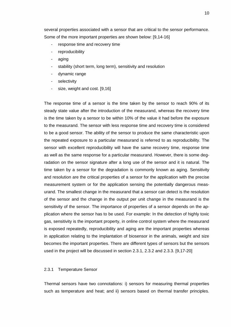
3.1 System Design
The system mainly comprises two parts: the mobile station and the microcontroller unit.
The mobile station is responsible for giving the command and the control instruction to
the devices and sensors and to get the response from them. It is just a user interface
and does not control the devices. The second unit, the microcontroller unit, is responsi-
ble for controlling the devices, processing information gathered from the devices as
well as from the mobile station. The microcontroller unit is the brain of the system and
controls and processes information to and from all other units of the system.
Figure 8: Block Diagram of the System
Motion
Detector
Heat
Detector
Intrusion
Detector Light
Arduino Microcontroller Board
Sim900 GSM/GPRS Module
Mobile
Phone

22
The block diagram of the system is shown in figure 8. As it is mentioned above, the
system comprises two units. The microcontroller unit consists of three sensors and a
light along with the sim900 module. Lm35 is the temperature detector, the digital output
proximity sensor is the intrusion detector and the Panasonic passive infrared sensor is
the motion detector of the system. The data from the sensors is continually processed
by the microcontroller and an alert is sent to the mobile station if something is sensed
or something reaches beyond the limit in case of a temperature sensor. Besides getting
the alert after reaching the limit, it is possible to know the temperature at home at any
time by sending an instruction to the microcontroller. These three units of the system
are responsible for the security of a home. The other part of the microcontroller unit is
the light system which can be operated remotely using the mobile stations. In this pro-
ject, a simple led light is used to show the demo of the remote light management sys-
tem. The user could get information about the state of light, whether it is ON or OFF, in
the mobile station and control the state of light remotely from the mobile station.
The Sim900 GPRS/GSM module acts as the mediator between the microcontroller unit
and the mobile station and is responsible for the communication between them. This
unit is responsible for sending information from the microcontroller to the mobile station
and for sending the instruction from the mobile station to the microcontroller. The in-
struction sent by the user from the mobile station is executed by the microcontroller. In
addition to the microcontroller unit, the second unit of the system is the mobile station
which is just a mobile phone. It does not require any special feature or any special ap-
plication for the mobile phone to be a part of the system. Any mobile phone supporting
the messaging application is suitable for the system. The instruction to the microcon-
troller is sent by using text messages and the alert from the microcontroller is received
as a text as well. The system acts as a smart home system providing security to the
home as well as providing a remote management system for the devices inside the
home.

23
3.2 Interfacing Sim900 GPRS/GSM Module
The Sim900 module is an important part of the system responsible for communication
between the microcontroller and the mobile phone. AT commands are used to interface
the module as well as to configure it. AT commands are inserted in C-language as a
string of characters which are sent to the module using the terminal program.
mySerial.println("AT+CPIN=4510"); //the pin code for
the sim
delay(5000);
mySerial.println("AT+CMGF=1"); //sets the text
mode
Listing 1: AT command syntax to set the text mode
The pin code of SIM is required to activate the SIM card. The instructions are defined
within a program as a C-language code which could be actuated at a specific moment.
The code would then be simply compiled and uploaded into the Arduino/GPRS shield
unit.
pos = msg.indexOf(",");
String index = msg.substring(pos+1); //the index
of SMS
mySerial.print("AT+CMGR = ");
mySerial.println(index);
//read the incoming SMS
Listing 2: AT commands to read the SMS message defined within a program
Listing 2 shows AT commands to find the index of the SMS and to read the contents of
the SMS message. It is necessary to read the index of the SMS every time with an in-
coming SMS message as the index keeps on increasing. Otherwise the program keeps
on reading the same SMS again and again even if there are new SMSs. Since the stor-
ing capacity of the SIM card is limited, the SMS is deleted after it is read and the in-
struction is executed. The microcontroller performs the action based on the instruction
sent by the mobile phone as an SMS message.
24
3.3 Interfacing and Implementing Sensors
There are different areas which have to be monitored frequently and devices which
have to be checked in and around the house. The doors and windows need to be moni-
tored from burglars if they try to open them as well as the movement of strangers
around the house premises should be monitored. Similarly, a member of the home
might want to know the state of electronic devices after leaving home and might need
to turn the devices off if they are left on. In addition, the temperature of the home has to
be monitored as well to trigger the alarm upon reaching the critical point. The monitor-
ing of temperature, a stranger’s movement and the opening and closing of doors and
windows are done by the designated sensors. The sensors could be implemented as
different types of detectors according to the necessity of the application and the human
desire. The operation of sensors is managed by software. Since there are different
types of sensors, they are interfaced according to the output and properties of the sen-
sor. The external circuit for interfacing the sensor for the application depends on the
type of the sensor and it is not a must as some of the sensors do not need it and the
output can be driven directly and used on the application.
3.3.1 Heat Detector
Temperature is among the areas to be monitored in a home and has to be known at
any time. As there is a saying, prevention is better than cure, it is better to monitor the
temperature of the house to prevent it from fire rather than extinguishing the fire, and it
is better to trigger the alarm that the house might be on fire rather than trigger the
alarm after it is on fire. Apart from this, a temperature sensor can be installed in a home
for various purposes, other than just as a fire alarm. It can be used in places such as a
cold room where the temperature has to be monitored carefully, so that the tempera-
ture would not rise above a certain point. Similarly, it can be used to check the warming
up of the house, so that the house will not warm above certain a temperature and the
electricity will not be used by the heating system after that point. It helps in the im-
provement of financial condition of the user by regulating the use of electricity. The
temperature sensor can be installed in a home and the temperature can be cross-
checked whenever desired by the owner. The limit could be set for the temperature to
trigger the alarm that the temperature is above the critical point. The critical point set
depends entirely on the place of installation. For example, the critical point for a sensor
installed in a cold room is very low compared to the critical point set for fire alarm.

25
The LM35 temperature sensor is used as the heat detector in the system. It is used as
a basic centigrade temperature sensor which can sense the temperature from +2 ºC to
+250 ºC. The power supply of 5V is used from the port of Arduino Board and the input
and output are connected to the input/output port of Arduino.
ND
Figure 9: Block diagram of the pin connection of LM35
The pin connection of LM35 is shown in figure 9. The analog input port A0 of the ardu-
ino board is used as the input port and the 5V output port of the arduino board is used
as the power supply for LM35. Since the sensor is used as a basic Centigrade tem-
perature sensor, any external circuit is not required and the output of the sensor can be
driven directly to the input port of the board.
Arduino Board Analog Input
GND 5V
pin1 pin 2 pin 3
LM35

26
The code used to interface the sensor and to calculate the temperature is shown be-
low:
int Temp_sensor = A0;
pinMode(Temp_sensor,INPUT);
volt_output = analogRead(Temp_sensor);
//reads the output
delay(1000);
temp = (5.0*volt_output*100)/1024;
if(temp > 45) //if the temperature
exceeds 45C,sends a SMS
{
send_SMS();
}
Listing 3: C code used to read the temperature
The microcontroller reads the output voltage of the sensor every second by using the
function analogRead. Temperature is the function of output voltage, and thus tempera-
ture can be calculated by using mathematics. The temperature is calculated from the
output voltage by using the formula shown in listing 3 and if it exceeds the limit defined
in the software, it will automatically send an SMS to the mobile phone specified in the
software. The limit of the temperature to send the SMS can be changed depending on
the environment of the place where the sensor is placed and on the application. For
example, if the sensor is placed in a cold room to maintain the temperature of the
room, the limit should be very low, and if the sensor is placed in a room to detect a fire,
the limit should be high. In addition, it is possible to get the temperature of the place
where the sensor is located by simply sending an SMS to the GPRS module.
3.3.2 Motion Detector
Motion detectors are used to detect the unwanted movement of people around the re-
stricted premises. Hence, the passive Infrared sensors could be used as a motion de-
tector and the alarm could be triggered if there is some movement around the restricted
premises. The passive Infrared sensor manufactured by Panasonic is used as a motion
detector in the system. The 5V power supply is given to the sensor through the board
and the output of the sensor is connected to the digital input of the arduino board. The
digital output timing chart of the infrared sensor is shown in figure 10.
27
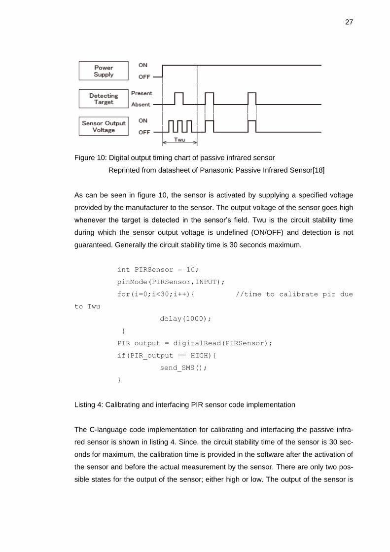
Figure 10: Digital output timing chart of passive infrared sensor
Reprinted from datasheet of Panasonic Passive Infrared Sensor[18]
As can be seen in figure 10, the sensor is activated by supplying a specified voltage
provided by the manufacturer to the sensor. The output voltage of the sensor goes high
whenever the target is detected in the sensor’s field. Twu is the circuit stability time
during which the sensor output voltage is undefined (ON/OFF) and detection is not
guaranteed. Generally the circuit stability time is 30 seconds maximum.
int PIRSensor = 10;
pinMode(PIRSensor,INPUT);
for(i=0;i<30;i++){ //time to calibrate pir due
to Twu
delay(1000);
}
PIR_output = digitalRead(PIRSensor);
if(PIR_output == HIGH){
send_SMS();
}
Listing 4: Calibrating and interfacing PIR sensor code implementation
The C-language code implementation for calibrating and interfacing the passive infra-
red sensor is shown in listing 4. Since, the circuit stability time of the sensor is 30 sec-
onds for maximum, the calibration time is provided in the software after the activation of
the sensor and before the actual measurement by the sensor. There are only two pos-
sible states for the output of the sensor; either high or low. The output of the sensor is

28
connected to the digital input port 10 of the board and the state is read in the software
by using the function digitalRead. As soon as there is some person’s movement around
the place where the sensor is installed, an alert will be sent to the mobile phone inform-
ing about the person’s movement.
3.3.3 Intrusion Detector
Generally, the intrusion sensors are placed at the doors and windows to detect the in-
trusion of a burglar in the home. The intrusion detector is used to give extra security
along with other detectors. The hall effect proximity sensor is manufactured by Comus
Europe Limited and works based on the hall effect principle. For the installation of the
proximity sensor, a magnet is attached to the frame of the door or window, whereas the
sensor is attached to the door or window itself. The magnet and the sensor should be
installed such that they are close to each other whenever the door or window is closed.
The south pole of the magnet should face the sensor on closure as the sensor is unipo-
lar hall effect proximity sensor.
Figure 11: Digital output timing chart of a hall effect proximity sensor
Figure 11 shows the digital output timing chart for the unipolar hall effect proximity sen-
sor. Since the sensor is a unipolar sensor, it is affected only by the south pole of the
magnet. The sensor is activated by supplying the specified voltage to the sensor and
the output value of the sensor goes low on the presence of the magnetic south pole, as
shown in figure 11.
The output of the sensor is low when the door or window is closed as the south pole of
the magnet is close to the sensor. Whenever the door is open, the door moves far from

29
the frame, which means that the sensor moves far from the magnet and the output of
the sensor goes high. The C-code implementation for interfacing the proximity sensor
is shown below:
int door_sensor=9;
pinMode(door_sensor,INPUT);
door_output=digitalRead(door_sensor);
if(door_output == LOW){
SMS_conten_flag_door=1;
send_SMS();
}
Listing 5: C-code compilation for interfacing proximity sensor
The C-code language for the interfacing and implementation of a proximity sensor is
shown in listing 5. The output of the sensor (either high or low) is read by the function
digitalRead. The output of the sensor goes low whenever the south pole of the magnet
comes close to the sensor and it sends the message. In this application, an SMS is
sent whenever the south pole of the magnet comes close to the sensor opposite to the
implementation of the door sensor installed at door/window explained above listing 5.
However the mechanism is the same and the implementation of the application can be
changed by changing a single C-code in the program.
3.4 Implementation of remotely managed light system
There are many electronic devices in the home whose status is unknown (on or off)
and which could be left on unknowingly or accidently. The status of the device has to
be known by the owner, and if the device is on, it has to be turned off. It is not always
possible to go back home and turn the devices off. There arises a need to manage the
electronic devices remotely to prevent the risk of some accidents as well as to de-
crease the use of electricity. There are different ways to implement remotely managed
electronic devices, for example management using the Ethernet, management using
wireless devices or management using the GPRS/GSM module. The electronic device
(the light system) is managed remotely using the GPRS/GSM module (especially using
the SMS) in this project. In this application, light is managed remotely, and the light
represents the electronic devices as a whole. Since the light uses a 220V AC current
and the arduino can provide only a 5V DC current, a relay is used in between the ardu-

30
ino and the light. The relay can be controlled by the I/O pins of the arduino which finally
controls the light. The circuit diagram to control the electronic devices using the I/O
pins of the Arduino Board via the relay shield is shown in figure 12.
Figure 12: Circuit diagram for the control of electronic devices
The electronic device is controlled by the I/O pin of arduino connected to the relay. The
com (common) is connected to NC (normally closed) when the I/O pin is low and the
com is connected to the NO (normally open) when the I/O pin is high. It means that the
electronic device is on when the I/O pin is high and the device is off when the I/O is
low. Basically, the electronic device can be managed remotely just by managing the I/O
pin of the arduino board. To show the demo of the remotely managed light, a led is
used, and it is controlled remotely in this application instead of the light bulb. The
principle of management of light is the same as the principle of management of led; the
Relay Shield
Arduino Board
In
gnd
vcc gnd
5V gnd I/O
com NO NC
Power
Supply
220V
Electronic
Devices

31
light is controlled by the I/O pins of the arduino via relays and the led is controlled by
the I/O pins itself.
int led = 13;
pinMode(led,OUTPUT);
if(msg.indexOf("Turn light on") >= 0){
digitalWrite(led,HIGH);
}
if (msg.indexOf("Turn light OFF") >= 0){
digitalWrite(led,LOW);
}
if(msg.indexOf("State of light") >= 0){
val = bitRead(PORTB,5);
switch(val){
case 0:
send_SMS();
break;
case 1:
send_SMS();
break;
}
}
Listing 6: C-code compilation for management of light remotely
Listing 6 shows the C-code compilation for the management of light remotely using a
mobile phone. The code first checks the SMS messages and does the operation ac-
cording to the content of the messages. The light will turn on or off according to the
instruction sent by the mobile phone by the function shown in listing 6. The fifth bit of
the B port holds the status of the light (i.e. the status of the I/O pin 13) and it is read by
the function bitRead. Upon the query of the status of light, an SMS is sent back to the
mobile phone containing the status of light. In this way, the status of light can be known
remotely and the light can be turned on or off with the help of a mobile phone remotely.
32
3.5 System development
The smart home system was developed by implementing the sensors and the remotely
managed light system in this project. In this project, only one light system was used to
show the demo of remotely managed electronic devices along with three detectors: an
LM35 temperature sensor as the heat detector, a Panasonic passive infrared sensor as
the motion detector and a hall effect proximity sensor as the intrusion detector. The
number of sensors used and the electronic devices managed remotely can be in-
creased or decreased according to the necessity of the application. This project was
the demonstration project of the smart home system using three sensors and a light
system. The smart home system triggered alarms to intrusion into the house through
doors and windows as well as to the movement of a human being around the premises
and around the restricted areas. The system also kept surveillance over the tempera-
ture and triggered alarm upon reaching the critical point and above it. The whole sys-
tem was the integration of implementation of the sensors and the light system de-
scribed individually in chapters 3.2, 3.3 and 3.4. The system is implemented on Arduino
platform using the Arduino Uno Board.
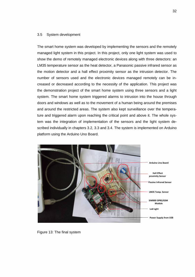
Figure 13: The final system

33
Figure 13 shows the microcontroller unit with the Arduino board, GPRS shield, light and
sensors. Power supply to the unit can be provided externally or from the USB port of
the computer. The power supply is supplied from the USB port in this project and the
sensors and the GPRS shield drives the power from the unit. The connection of differ-
ent sensors and the shield can be seen in figure 13. The whole system is implemented
using the C-code language written on the arduino platform. The software written on the
platform can be uploaded to the microcontroller (i.e. the arduino board) using Arduino
IDE software.
Figure 14: Screenshot of the Arduino Software IDE
The Arduino integrated development environment (IDE) is a cross-platform written in
Java, whereas the programs are written in C or C++, which is shown in figure 14. The
platform comes with a software library along with the code editor with features such as
syntax highlighting, brace matching and automatic indentation. The whole program is
written in the platform in the C language code which can be uploaded to the board by a
simple upload button. Basically, the project is the integration of the software (C lan-
guage code) used to interface and implement the sensors, the GPRS module and the
remote management of light. In addition, the program contains some more code to co-
ordinate among those parts along with some extra C code rather than the individual
codes described above.

34
The application is a system from the hardware and software integration of different
modules along with the mobile station. The sensors along with the light and the GPRS
module are connected to the arduino board and the application program which controls
the microcontroller is written in arduino IDE as a C language code which can be up-
loaded to the board with the help of a single button. It is always better to have a com-
mon ground of the system for better operation of the application, which is also followed
here as the system has a common ground. The mobile station (or simply the mobile
phone) interacts with the arduino board with the help of the GPRS module connected
to the board. The main function of the mobile station is to give instructions to the micro-
controller along with receiving the alerts sent from the microcontroller. The instructions
and alerts are sent and received as an SMS message with the help of the GSM net-
work available. There is no need for developing any new features in the mobile phone
to use this system. Any simple mobile phone supporting the SMS can be used as the
mobile station in this application.
3.6 Testing the system
First of all, all the hardware units of the system were tested and it was ensured that
they were in a good working condition. Then, each and every unit were interfaced and
implemented individually with the microcontroller board and drove with the software
according to the necessity of the application. The testing of the application was not
done at once after it was completed. Rather each unit of the application was tested
individually. The second unit was not tested until the first unit gave the expected result
and until it was not working according to the necessity of the application. After all of the
units were working correctly, the units were kept together and then the whole system
was developed and tested. It was easy to figure out the bugs and the problem of the
system as the behaviour of each unit was known while testing it. It would be impossible
to figure out the problems and the bugs in the system if the system was developed and
tested after it was completed. After the hardware units were tested, the communication
of the mobile station with the GPRS module was tested.

35
Figure 15: Screenshot of the terminal program testing the communication of the GPRS
module with the mobile station

36
Figure 15 illustrates the communication of the GPRS module with the mobile station
captured in a terminal program. It can be seen from figure 15 that the SIM is active and
it is connected to Sonera’s GSM network. Similarly, the module is able to call a specific
number as well as the module can be operated in text mode and a message can be
sent to a specific number. The mobile phones used to test communication along with
the whole system are Samsung Galaxy s4 and HTC desire.
After it was made sure that the communication of the mobile station with the GPRS
module was working according to our wish, the sensors were interfaced with the micro-
controller and the result were captured and analysed with the help of a terminal pro-
gram. Finally all the hardware and software were integrated and the whole system was
developed after the sensors were working correctly.
Figure 16: Screenshot of the terminal program testing the final system design

37
Figure 16 illustrates the screenshot of the system. The system keeps on reading the
temperature continuously and the output of the proximity sensor and the infrared sen-
sor at an interval of one second. The system will read the incoming message immedi-
ately after it is received and an SMS will be sent if any alarm is triggered in between
reading the outputs. Then the system again starts to read the outputs at an interval of
one second. As can be seen from figure 16, the system reads an incoming message
state of light and sends back the response. The response sent can be seen as +CMGS
137 and OK in the terminal program.

38
4 Result
The aim of the project was to implement a smart home system and the goal was met.
The microcontroller unit responds to the instructions sent by the mobile phone accord-
ing to the necessity of the application as well as triggers the alarm upon a critical situa-
tion. The aim of the application to manage the electronic devices remotely was also
achieved.
Table 2: Result of the instructions and the response to and from the mobile station
Unit Instruction sent by
mobile
Response to the
mobile
Output/Alarm
triggering
condition
Light State of light The light is ON/OFF
Turn light on Light is turned
ON
Turn light OFF Light is turned
OFF
Heat detector What is the
temperature?
The temperature is x
ºC
The temperature is
too high
If the tempera-
ture is > y ºC
Intrusion detector Someone has
opened the door
If the output of
the proximity
sensor is low
Motion detector Someone is moving
around the house
If the output of
the PIR sensor
is high
Table 2 shows the instructions sent to the microcontroller from the mobile station and
output of the instructions as well as the response sent to the mobile station from the
microcontroller respectively. As can be seen from table 2, the instructions are sent only
to the light system and the temperature sensor and they behave according to the in-
struction sent by the mobile phone. However the PIR sensor and the proximity sensor
will trigger alarm if there is some movement around the restricted premises or if some-
one tries to intrude into the building through doors or windows.

39
Figure 18: Screenshot of the mobile station managing the light remotely
Figure 18 shows a screenshot of management of electronic devices (light system) by
the mobile station (i.e. the mobile phone). As can be seen from figure 18, the microcon-
troller will send a response to the mobile phone as an SMS mentioning whether the
light is on or off upon the instruction (state of light) sent by the mobile phone. The light
can be turned on and off by the SMS which can be visualised, and the response to the
instruction will also be different when the light is on or off which can be seen in figure
18.

40
Figure 19: Screenshot of the response and alarms received by the mobile station
Figure 19 shows a response sent to the mobile station upon the instruction (What is the
temperature?) sent by the mobile station and the alarms triggered upon the critical
condition. The SMS sent by the microcontroller is different for the alarms triggered by

41
different sensors. Hence, it is possible to know the sensor responsible for triggering the
alarm and getting some idea of the condition of the premises. It can be seen from fig-
ures 18 and 19 that the result of the application meets the concept and the motives of
the system.

42
5 Discussion
The development of technology has been affecting the life style of people. They are
dependent on technology even to carry out daily activities and technology has made
the lifestyle more sophisticated and relaxing. It seems as if it was impossible to live
without technology in this century. Advanced technology has replaced the traditional
lifestyle of people. For example, a coffee machine has replaced the traditional way of
coffee making, finger-print and voice-controlled electronic lock have replaced traditional
locks, electronic news and media have replaced the traditional paper news and media,
bank cards and online shopping have replaced the traditional cash and shopping. The
examples mentioned above are a few least advanced technologies replacing the tradi-
tional lifestyle. Besides these, there are many advanced technologies used by people
for different purposes, they are playing significant roles in changing the lifestyle of peo-
ple. With the development of technology, the concept of simple home has also been
changing into smart home and the concept of home has changed drastically during the
last decade.
The advancement of technology has not only played a significant role in the develop-
ment of positive aspects but has also played an important role in the development of
negative aspects. It has increased the risk of burglary and intrusion using the latest
modern technologies available. The busy lifestyle of human beings along with the in-
creasing risk has led to the necessity of remote surveillance of homes. There are dif-
ferent ways to have the surveillance but the easiest and most advanced technology
accessible to everybody is mobile phone surveillance. The mobile phone can be used
for different purposes with the help of the applications developed for the phones.
This project was a simple application project demonstrating a smart home system. The
led light (representing the electronic devices) is controlled by the mobile phone using
the SMS service and the surveillance of the home is done using the mobile phone. The
mobile phone gets alerts on intrusion or movement around the restricted premises
along with the rise in temperature above the limit. The movements and the temperature
are detected by installing sensors at different places. The temperature of the premises
where the sensors are installed can be known at any time before reaching the critical
limit set by the user. The intrusion is detected by the hall effect proximity sensor,
movement by the PIR sensor and temperature by the temperature sensor.

43
As this project was a simple smart home system demonstration project, a few sensors
and a led light were used. The project can be extended by increasing the number of
sensors used along with an increase in the number of installation places. The remote
management of electronic devices can also be extended with the use of different real
electronic devices. Similarly, the project is limited to the availability of the GSM network
as the GPRS module and the mobile phone itself uses the GSM network available for
communication. The application can be developed further using different wireless tech-
nologies such as the Bluetooth technology and infrared technology or the Internet to
communicate between the microcontroller unit and the mobile phone. The hardware,
the software and the mechanism used in this project can be implemented to develop a
complete smart home system.
The project was completed within the projected time with the expected result. However,
there were many hardware and software errors experienced during the development of
the application. There were many bugs in the software as well as connection errors in
the hardware, which came along with the development of the application and which
were solved individually. Despite reading the datasheet of the sensors before using
them, the PIR sensor was burnt out by accidentally connecting the wrong pins. Acci-
dentally, the ground connection and the power supply were interchanged which burnt
down the sensor and a new sensor had to be ordered. Similarly, there were some
hardware errors while connecting the sensors and the led with the microcontroller.
Many connection errors were faced during the project time which did not lead to the
damage of any hardware unit except the PIR sensor which was fixed up later.
Besides the connection error, there were many bugs in the software of the system
which were identified and fixed up eventually. The first problem was encountered while
reading the SMS message containing the instruction by the mobile station. The first
message was read successfully but the message after the first one could not be read.
pos = msg.indexOf(","); //search for the position of ,
String index = msg.substring(pos+1); //the index
of SMS to be read
Serial.println(index);
mySerial.print("AT+CMGR = ");
mySerial.println(index);
Listing 7: C-code implementation for determining the index of SMS

44
Listing 7 illustrates the C code implementation for determining the index of the SMS
message which has to be read. The code mentioned above finds the index of the in-
coming message and processes it. The index of the SMS was determined correctly for
the first incoming SMS but the index of the SMS after that could not be determined and
the message could not be processed. Initially it was thought that there was some prob-
lem with the code but the problem was the RX buffer of the GPRS module which was
found later. Whenever the first message was processed, it was stored in the RX buffer
of the module and the code was finding the position of comma to determine the index
of the SMS. Hence, the output of the code was something else than the index as the
code found the position of the comma of the previously processed message stored in
the buffer and the string after the comma which was the index. Since the code found a
different comma, the string after that was also different than the index and the message
could not be processed as the index was not correct. The problem was solved by clear-
ing the RX buffer each time after processing the SMS. The clearing of the SMS was
done by the function given below:
mySerial.flush();.
The system gives the flexibility to the type and number of sensors used compared to
the already built security system bought from the market. The opportunity is given to
the user to choose the type of sensor and to set the limit to trigger alarm as well. The
cost of the system can be determined by the user as the cost of the system includes
the cost of the hardware units determined by the user. The behaviour of the system
can be changed according to the necessity of the user by adjusting the hardware and
software of the system. The system is more flexible and user-friendly compared to the
security system available in the market. Many new experiences and knowledge were
gained during the project.

45
6 Conclusion
The goal of the project was to implement a smart home system by controlling the elec-
tronic devices at home remotely with a mobile phone and to receive alerts on intrusion
and movement around restricted premises. The goal was achieved successfully. The
devices were controlled by sending instructions as an SMS and the alerts were re-
ceived as an SMS as well. A hall effect proximity sensor and a passive infrared sensor
were used as detectors to detect the intrusion and movement around the restricted
premises respectively. A temperature sensor was used as a heat detector and a led
light was used to show the demonstration of an electronic device management. Ardu-
ino Uno Board was used as a microcontroller while the SIM900 GPRS/GSM model was
used for communication between the microcontroller unit and the mobile station. The
mobile phone did not need to have any special application or hardware to be used as a
mobile station. Any mobile phone supporting the SMS could be used as a mobile sta-
tion.
There are many smart home systems available in the market costing hundreds of eu-
ros. Designing one’s own home security system will save hundreds of euros as it is
cheaper and the cost could be decided by the designer who is the ultimate user of the
system. Not only the economic side but also the technical side is more flexible with this
concept. With this concept, the designer could be able to decide the type and number
of sensors to be used and the area to be covered. The systems available in the market
are limited to number, type and area of coverage as well as to the number of electronic
devices that could be controlled. Flexibility to the number of electronic devices con-
trolled was also available in the application.
Flexibility with the technical customisation and economy are the main advantages of
the design. However the system is limited to the GSM network available and will not
work if the GSM network is not available. The IR sensor could be triggered with the
movement of some animals such as a rat around the premises or by light striking the
sensor directly, which could trigger a false alarm. The project could be further extended
by using other technologies for communication, for example wireless communication
using radio frequency, the Bluetooth technology or the Internet. The ideas and informa-
tion used in the design could be used for development of smart a home system.

46
References
1 Arduino. Introduction to Arduino [Online]. Italy: Arduino URL: http://arduino.cc/en/Guide/Introduction Accessed July 15 2013
2 Arduino. Arduino board Uno [Online]. Italy: Arduino URL: http://arduino.cc/en/Main/ArduinoBoardUno Accessed 17 July 2013
3 Atmel Corporation. ATmega328 datasheet [Online]. USA: Atmel Corporation; 10/2009 URL: http://www.atmel.com/Images/doc8161.pdf Accessed 11 July 2013
4 Anttalainen T. Telecommunications Network Engineering. 2nd ed. London: Artech House Inc; 2003.
5 ActiveXperts Software B.V. GPRS Introduction [Online]. The Netherlands: Ac-tiveXperts Software B.V. URL : http://www.activexperts.com/mmserver/cellular/gprsintro/ Accessed 18 July 2013
6 SIMCom Wireless Solutions Co. Ltd. SIM900 Specifications [Online]. China: SIMCom Wireless Solutions Co Ltd. URL: http://wm.sim.com/producten.aspx?id=1019 Accessed 18 July 2013
7 Syeda Anila Nursat. Introduction to AT commands and its uses [Online]. Paki-stan: Software Developer Syndustria Pvt. Ltd; 2010. URL: http://www.codeproject.com/Articles/85636/Introduction-to-AT-commands-and-its-uses Accessed 23 July 2013
8 Patranabis D. Sensors and Transducers. 2nd ed. India: PHI Learning Pvt. Ltd; 2003.
9 Vetelino J. and Raghu A. Introduction to Sensors. USA: CRC Press; 2011.
10 Chang Liu. Foundations of MEMS. 2nd ed. USA: Prentice Hall; 2010.
11 Newman R. and Elena Gaura. Smart MEMS and Sensor Systems. England: Im-perial College Press; 2006.
12 Watlow Missouri Inc. The Watlow Educational Series Book Four, Temperature Sensors [Online]. USA: Watlow Missouri Inc. URL: http://www.mc.co.il/Media/Doc/TechnicalInformation/Temp_Measuring1.pdf Accessed 30 July 2013

47
13 Bernie Siegal. An Introduction to diode thermal measurements [Online]. USA: Thermal Engineering Associates; 2009. URL: http://www.thermengr.net/An_Introduction_to_Diode_Thermal_Measurements6.pdf Accessed 2 August 2013
14 Texas Instruments. LM35 Precision Centigrade Temperature Sensors. USA: Texas Instruments; 2013. URL: http://www.ti.com/lit/ds/symlink/lm35.pdf Accessed 3 August 2013
15 Helmut Budzier and Geerald Gerlach. Thermal Infrared Sensors: Theory, Optimi-sation and Practice. UK: Wiley Publisher; 2011.
16 International Commision on Illumination. International Lighting Vocabulary. 3rd ed. Paris;1970 (publication no 17 E(1.1)).
17 Dipaola A. and Dipaola S. Introduction to Low Voltage Systems. 2nd ed. USA: Cengage Learning; 2012
18 Panasonic Electric Works Corporation of America. Passive Infrared Motion Sen-sors [Online]. USA: Panasonic Electric Works Corporation of America. URL: http://www.farnell.com/datasheets/1537854.pdf Accessed 6 August 2013
19 Boll R. and Overshott J. Sensors: A Comprehensive Survey, Magnetic Sensors Volume 5. USA: VCH Publishers Inc; 1989
20 Edward Ramsden. Hall-Effect Sensors: Theory and Application. 2nd ed. U.K: El-sevier Inc; 2006.
21 Honeywell International Inc. Hall Effect Sensing and Application [Online]. USA: Honeywell International Inc. URL: http://sensing.honeywell.com/index.php?ci_id=47847 Accessed 7 August 2013.
22 Comus Europe Ltd. Datasheet of Digital Hall Effect Proximity Sensor. U.K: Comus Europe Ltd; 2009. URL: http://www.farnell.com/datasheets/1657826.pdf Accessed 7 August 2013

48

Appendix 1
1 (7)
C-language code of the system
#include <SoftwareSerial.h>
#include "pins_arduino.h"
#include <String.h>
SoftwareSerial mySerial(7, 8);
String msg = String("");
char data;
//int alarm_light = 5;
int led = 13;
int Temp_sensor = A0;
int door_snsr=9;
int pir_snsr=10;
int val,pos,output,door_output,pir_output;
int count_pir=0;
int ind_pir=0;
int ind_temp=0;
int count_temp = 0;
float temp;
String index;
boolean sms_content_flag_on = 0;
boolean sms_content_flag_off = 0;
boolean sms_content_flag_critical = 0;
boolean sms_content_flag_temp = 0;
boolean sms_content_flag_door = 0;
boolean sms_content_flag_pir = 0;
void setup()
{
mySerial.begin(19200); // the GPRS baud
rate
Serial.begin(19200); // the Serial port
of Arduino baud rate.
delay(500);
mySerial.println("AT+CPIN=4510"); //the pin code for the
sim
delay(5000);
mySerial.println("AT+CMGF=1"); //sets the text mode
delay(1000);
pinMode(led,OUTPUT);
pinMode(door_snsr,INPUT);
pinMode(pir_snsr,INPUT);
//pinMode(alarm_light,OUTPUT);
pinMode(Temp_sensor,INPUT);
//digitalWrite(led,HIGH);
//delay(500);
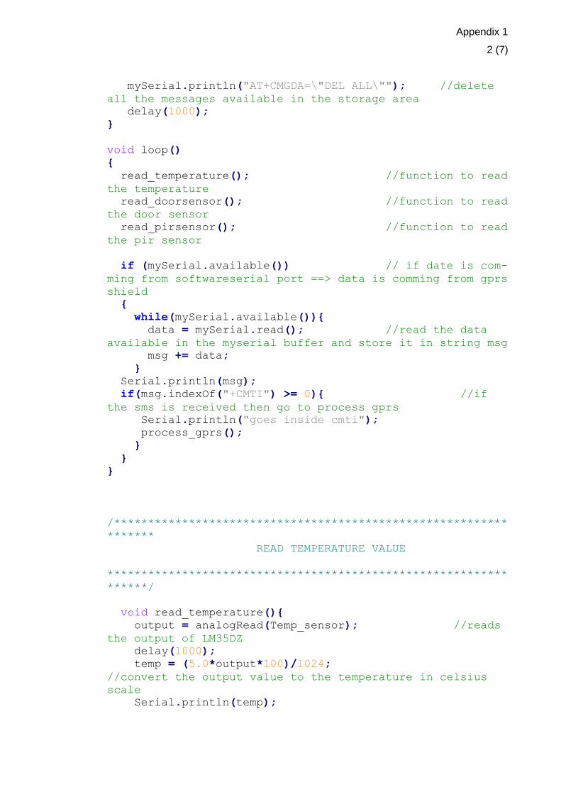
Appendix 1
2 (7)
mySerial.println("AT+CMGDA=\"DEL ALL\""); //delete
all the messages available in the storage area
delay(1000);
}
void loop()
{
read_temperature(); //function to read
the temperature
read_doorsensor(); //function to read
the door sensor
read_pirsensor(); //function to read
the pir sensor
if (mySerial.available()) // if date is com-
ming from softwareserial port ==> data is comming from gprs
shield
{
while(mySerial.available()){
data = mySerial.read(); //read the data
available in the myserial buffer and store it in string msg
msg += data;
}
Serial.println(msg);
if(msg.indexOf("+CMTI") >= 0){ //if
the sms is received then go to process gprs
Serial.println("goes inside cmti");
process_gprs();
}
}
}
/**********************************************************
*******
READ TEMPERATURE VALUE
***********************************************************
******/
void read_temperature(){
output = analogRead(Temp_sensor); //reads
the output of LM35DZ
delay(1000);
temp = (5.0*output*100)/1024;
//convert the output value to the temperature in celsius
scale
Serial.println(temp);

Appendix 1
3 (7)
if(temp > 23) //if the
temperature exceeds 45C,sends an sms to the number
{
count_temp=count_temp+1;
Serial.println(count_temp);
if(count_temp == 1 || count_temp == 5*ind_temp){
//sends the sms message after each 5 temperature value
greater than critical set
//digitalWrite(alarm_light,HIGH);
sms_content_flag_critical = 1;
send_sms();
}
}
}
/**********************************************************
******
READ THE DOOR SENSOR
***********************************************************
******/
void read_doorsensor()
{
door_output = digitalRead(door_snsr);
delay(1000);
Serial.println(door_output);
if(door_output == LOW){
sms_content_flag_door = 1;
send_sms();
}
}
/**********************************************************
READ THE PIR SENSOR
***********************************************************
**/
void read_pirsensor()
{
pir_output = digitalRead(pir_snsr);
delay(1000);

Appendix 1
4 (7)
Serial.println(pir_output);
if(pir_output == HIGH){
count_pir = count_pir+1;
Serial.println(count_pir);
if(count_pir == 1 || count_pir == 5*ind_pir){
sms_content_flag_pir = 1;
send_sms();
}
}
}
/**********************************************************
************
SEARCH THE INDEX OF THE SMS AND READ THE CONTENT OF THE
SMS MESSAGE
***********************************************************
**********/
void process_gprs(){
pos = msg.indexOf(",");
//search for the position of , to find the index of sms
//Serial.println(pos);
String index = msg.substring(pos+1);
//the index of sms to be processed
Serial.println(index);
mySerial.print("AT+CMGR = ");
mySerial.println(index);
//read the incoming sms
delay(1000);
if(msg.indexOf("+CMGR") >=0){
Serial.println("goes inside cmgr");
process_sms();
}
}
/**********************************************************
********
PERFORMS THE ACTION ACCORDING TO THE CONTENT OF THE MES-
SAGE
***********************************************************
******/
void process_sms(){
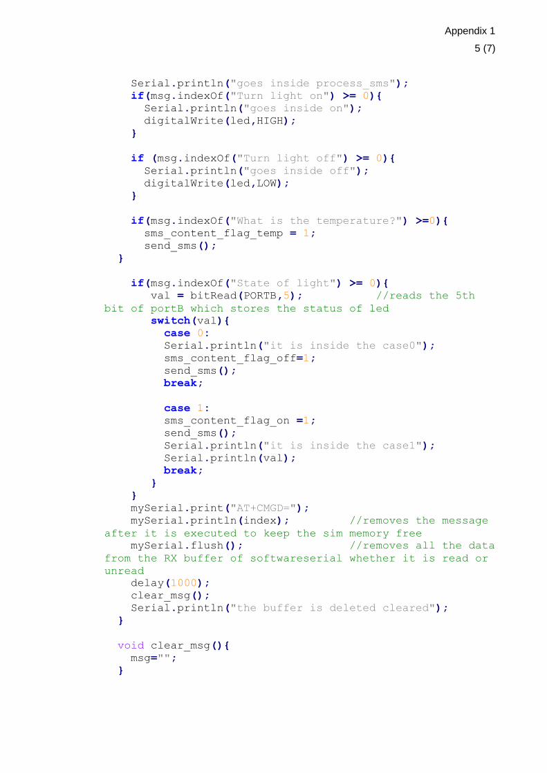
Appendix 1
5 (7)
Serial.println("goes inside process_sms");
if(msg.indexOf("Turn light on") >= 0){
Serial.println("goes inside on");
digitalWrite(led,HIGH);
}
if (msg.indexOf("Turn light off") >= 0){
Serial.println("goes inside off");
digitalWrite(led,LOW);
}
if(msg.indexOf("What is the temperature?") >=0){
sms_content_flag_temp = 1;
send_sms();
}
if(msg.indexOf("State of light") >= 0){
val = bitRead(PORTB,5); //reads the 5th
bit of portB which stores the status of led
switch(val){
case 0:
Serial.println("it is inside the case0");
sms_content_flag_off=1;
send_sms();
break;
case 1:
sms_content_flag_on =1;
send_sms();
Serial.println("it is inside the case1");
Serial.println(val);
break;
}
}
mySerial.print("AT+CMGD=");
mySerial.println(index); //removes the message
after it is executed to keep the sim memory free
mySerial.flush(); //removes all the data
from the RX buffer of softwareserial whether it is read or
unread
delay(1000);
clear_msg();
Serial.println("the buffer is deleted cleared");
}
void clear_msg(){
msg="";
}

Appendix 1
6 (7)
/***********************************************
SENDS THE SMS MESSAGES TO THE MOBILE PHONE
**********************************************/
void send_sms(){
//mySerial.println("AT+CMGF=1");
mySerial.println("AT + CMGS =
\"+358443507372\"");//send sms message, be careful need to
delay(100);
//add a country code before the cellphone number
if(sms_content_flag_on == 1)
mySerial.println("The light is on ");//the content of
the message
if(sms_content_flag_off == 1)
mySerial.println("The light is off ");
if(sms_content_flag_critical == 1){
ind_temp++;
mySerial.println("The temperature is too high ");
}
if(sms_content_flag_door == 1)
mySerial.println("someone has opened the door ");
if(sms_content_flag_pir == 1){
ind_pir++;
mySerial.println("Someone is moving around your
house");
}
if(sms_content_flag_temp == 1){
mySerial.println("The temperature is ");
mySerial.println(temp);
}
delay(100);
mySerial.println((char)26);//the ASCII code of the
ctrl+z is 26
delay(100);
mySerial.println();
clear_sms_content_flags();
msg="";
}
/*****************************************************
CLEARS THE FLAGS SET
****************************************************/
void clear_sms_content_flags(){
Appendix 1
7 (7)
sms_content_flag_on = 0;
sms_content_flag_off = 0;
sms_content_flag_critical = 0;
sms_content_flag_temp = 0;
sms_content_flag_door = 0;
sms_content_flag_pir = 0;
}
.

Appendix 2
1 (1)


![sim900 and mobile[].pdf](https://static.fdocuments.net/doc/165x107/55cf9309550346f57b9b323f/sim900-and-mobilewwwiranmicroirpdf.jpg)