DESIGN AND IMPLEMENTATION OF A FLIGHT CONTROL …uav.ece.nus.edu.sg/~bmchen/papers/ASJC2013.pdf ·...
25
DESIGN AND IMPLEMENTATION OF A FLIGHT CONTROL SYSTEM FOR AN UNMANNED ROTORCRAFT USING RPT CONTROL APPROACH Guowei Cai, Biao Wang, Ben M. Chen, and Tong H. Lee ABSTRACT In this paper, we apply a so-called robust and perfect tracking (RPT) control technique to the design and implementation of the flight control system of a miniature unmanned rotorcraft, named HeLion.To make the presented work self-contained, we will first outline some background knowledge, including mainly the nonlinear flight dynamics model and the inner-loop flight control system design. Next, the highlight of this paper, that is, the outer-loop flight control system design procedure using RPT control technique, will be detailed. Generally speaking, RPT control technique aims to design a controller such that (i) the resulting closed-loop system is asymptotically stable, and (ii) the controlled output almost perfectly tracks a given reference signal in the presence of any initial conditions and external disturbances. Since it makes use of all possible information including the system measurement output and the command reference signal together with all its derivatives (if available) for control, RPT control technique is particularly useful for the outer-loop layer of an unmanned aircraft. Both simulation and flight-test results will be presented and analyzed at the end of this paper, and the efficiency of the RPT control approach will be evaluated comprehensively. Key Words: Unmanned aerial vehicles, flight control systems, robust control, tracking control. I. INTRODUCTION During the last two decades, miniature unmanned- aerial-vehicle (UAV) helicopters have gained great attention in academic circles worldwide. Some unique features such as low cost, good maneuverability, and easy maintenance, make them an ideal experimental platform for various research purposes. Their growing popularity in the last several years has been further revealed by some successful and impressive implementations (see, for example, [1,12,23,29]). The automatic flight control system is essen- tial for a UAV to carry out flight missions with minimal or even without interference from human pilots. The classical single-input/single-output (SISO) feedback control method (i.e., PD or PID control) is one of the most common choices because of its simplicity in structure with less requirement on the accuracy of the dynamical model of the UAV. Exam- ples include the CMU-R50 UAV helicopter [24], in which a SISO PD control law is adopted and further optimized using CONDUIT for both hovering and forward flight, and the Ursa Major 3 UAV helicopter [27], in which a SISO PID control is implemented for automatic hovering. To improve flight control performance, many researchers are devoted to the study of implementing more advanced control techniques on the miniature rotorcraft UAVs. For example, a flight control system using a MIMO (multi-input/multi-output) H• control approach has been designed and implemented for their mini rotorcraft UAVs in [34]. It is reported that the resulting system has clearly outperformed the classical method. Other cases reported in the literature include systems designed by using: (i) a decentralized decoupled model predictive approach [28]; (ii) a neural network method [15,32]; (iii) adaptive control techniques [11,22]; (iv) a fuzzy logic approach [20]; (v) m-synthesis [33]; (vi) an approximate lin- earization method [21]; (vii) nonlinear control methods [3,26]; (viii) a differential geometry technique [19]; (ix) H• control [16,17]; (x) a learning control technique [14]; (xi) intelligent control methods [31]; and (xii) a sliding mode control technique [13], to name a few. After decades of development, although there is a vast number of works that have been performed along these lines, many are still in the simulation stage. They are still not ready for reliable and mature implementations onto real platforms. Recently, Cai et al. [4,5] (see also Peng et al. [25]) have proposed a flight control scheme consisting of three parts, Manuscript received March 7, 2011; revised September 5, 2011; accepted Novem- ber 6, 2011. Guowei Cai is with Temasek Laboratories, National University of Singapore, Sin- gapore 117411. Biao Wang, Ben M. Chen (corresponding author) and Tong H. Lee are with the Department of Electrical & Computer Engineering, National University of Singapore, Singapore 117576 (e-mails: [email protected]; [email protected]; bmchen@ nus.edu.sg; [email protected]). Asian Journal of Control, Vol. 15, No. 1, pp. 95–119, January 2013 Published online 14 February 2012 in Wiley Online Library (wileyonlinelibrary.com) DOI: 10.1002/asjc.504 © 2012 John Wiley and Sons Asia Pte Ltd and Chinese Automatic Control Society
Transcript of DESIGN AND IMPLEMENTATION OF A FLIGHT CONTROL …uav.ece.nus.edu.sg/~bmchen/papers/ASJC2013.pdf ·...

DESIGN AND IMPLEMENTATION OF A FLIGHT CONTROL SYSTEMFOR AN UNMANNED ROTORCRAFT USING RPT
CONTROL APPROACH
Guowei Cai, Biao Wang, Ben M. Chen, and Tong H. Lee
ABSTRACT
In this paper, we apply a so-called robust and perfect tracking (RPT) control technique to the design and implementationof the flight control system of a miniature unmanned rotorcraft, named HeLion. To make the presented work self-contained, wewill first outline some background knowledge, including mainly the nonlinear flight dynamics model and the inner-loop flightcontrol system design. Next, the highlight of this paper, that is, the outer-loop flight control system design procedure using RPTcontrol technique, will be detailed. Generally speaking, RPT control technique aims to design a controller such that (i) theresulting closed-loop system is asymptotically stable, and (ii) the controlled output almost perfectly tracks a given referencesignal in the presence of any initial conditions and external disturbances. Since it makes use of all possible information includingthe system measurement output and the command reference signal together with all its derivatives (if available) for control, RPTcontrol technique is particularly useful for the outer-loop layer of an unmanned aircraft. Both simulation and flight-test resultswill be presented and analyzed at the end of this paper, and the efficiency of the RPT control approach will be evaluatedcomprehensively.
Key Words: Unmanned aerial vehicles, flight control systems, robust control, tracking control.
I. INTRODUCTION
During the last two decades, miniature unmanned-aerial-vehicle (UAV) helicopters have gained great attentionin academic circles worldwide. Some unique features suchas low cost, good maneuverability, and easy maintenance,make them an ideal experimental platform for variousresearch purposes. Their growing popularity in the lastseveral years has been further revealed by some successfuland impressive implementations (see, for example,[1,12,23,29]). The automatic flight control system is essen-tial for a UAV to carry out flight missions with minimal oreven without interference from human pilots. The classicalsingle-input/single-output (SISO) feedback control method(i.e., PD or PID control) is one of the most common choicesbecause of its simplicity in structure with less requirementon the accuracy of the dynamical model of the UAV. Exam-ples include the CMU-R50 UAV helicopter [24], in which aSISO PD control law is adopted and further optimized using
CONDUIT for both hovering and forward flight, and the UrsaMajor 3 UAV helicopter [27], in which a SISO PID controlis implemented for automatic hovering. To improve flightcontrol performance, many researchers are devoted to thestudy of implementing more advanced control techniques onthe miniature rotorcraft UAVs. For example, a flight controlsystem using a MIMO (multi-input/multi-output) H• controlapproach has been designed and implemented for their minirotorcraft UAVs in [34]. It is reported that the resultingsystem has clearly outperformed the classical method. Othercases reported in the literature include systems designedby using: (i) a decentralized decoupled model predictiveapproach [28]; (ii) a neural network method [15,32]; (iii)adaptive control techniques [11,22]; (iv) a fuzzy logicapproach [20]; (v) m-synthesis [33]; (vi) an approximate lin-earization method [21]; (vii) nonlinear control methods[3,26]; (viii) a differential geometry technique [19]; (ix) H•
control [16,17]; (x) a learning control technique [14]; (xi)intelligent control methods [31]; and (xii) a sliding modecontrol technique [13], to name a few. After decades ofdevelopment, although there is a vast number of works thathave been performed along these lines, many are still in thesimulation stage. They are still not ready for reliable andmature implementations onto real platforms.
Recently, Cai et al. [4,5] (see also Peng et al. [25]) haveproposed a flight control scheme consisting of three parts,
Manuscript received March 7, 2011; revised September 5, 2011; accepted Novem-ber 6, 2011.
Guowei Cai is with Temasek Laboratories, National University of Singapore, Sin-gapore 117411.
Biao Wang, Ben M. Chen (corresponding author) and Tong H. Lee are with theDepartment of Electrical & Computer Engineering, National University of Singapore,Singapore 117576 (e-mails: [email protected]; [email protected]; [email protected]; [email protected]).
Asian Journal of Control, Vol. 15, No. 1, pp. 95–119, January 2013Published online 14 February 2012 in Wiley Online Library (wileyonlinelibrary.com) DOI: 10.1002/asjc.504
© 2012 John Wiley and Sons Asia Pte Ltd and Chinese Automatic Control Society

namely, the inner-loop control, outer-loop control and flightscheduling (see Fig. 1). In [4], the function of the inner-loopcontrol law, designed using the H• control approach, is toguarantee the asymptotic stability of the aircraft motion withrespect to the surrounding air and to have good disturbancerejection with respect to wind gusts. The role of the outer-loop controller is to produce flight commands or references tothe inner-loop control layer, and lastly, the task of the flightscheduling part is to generate the flight references for pre-scheduled flight missions.
We would like to note that the outer-loop layerreported in [4] consists of a set of simple proportional con-trollers for which it is hard to push their overall perform-ance. In this paper, we propose the design of the outer-loopcontrollers for our unmanned helicopter system, HeLion [6](see Fig. 2). HeLion is the first miniature unmannedrotorcraft constructed at National University of Singapore.Using a Raptor 90-SE hobby helicopter as the baseline,HeLion is equipped with a compact and light-weight avionicsystem (developed by our NUS UAV research team) torealize high-performance fully autonomous flight. Morespecifically, the design method to be implemented is the
so-called robust and perfect tracking (RPT) control tech-nique. It was developed by Chen and his co-workers (see,e.g., [9,10]) and is capable of achieving much better per-formance for situations when complicated maneuvers arerequired. The robust and perfect tracking control techniqueis to design a controller such that the resulting closed-loopsystem is asymptotically stable and the controlled outputalmost perfectly tracks a given reference signal in the pres-ence of any initial conditions and external disturbances. Itmakes use of all possible information including the systemmeasurement output and the command reference signaltogether with all its derivatives, if available, for control.Such a unique feature is particularly useful for the outer-loop layer, in which the position reference and its velocity,as well as acceleration, all can be measured by the onboardavionic system. Our design has been successfully demon-strated in both simulation and actual flight tests. In fact, theflight control system within the RPT control frameworkrenders the flight formation of multiple UAVs a trivial task,i.e., there is no need to design an additional controller forrealizing flight formation of multiple vehicles.
The outline of this paper is as follows. In Section II, webriefly introduce some background material on the dynamicmodel of the unmanned rotorcraft and the inner-loop control-ler of the flight control system. Section III presents the RPTcontrol technique and the detailed design procedure for theouter-loop controllers of the unmanned system, and SectionIV gives the performance evaluation of our design throughsimulation and actual flight test results in a wide-envelopeflight mission. Finally, we draw some concluding remarks inSection V.
II. BACKGROUND MATERIAL
It is crucial to obtain a fairly comprehensive model of aUAV if one wishes to design an advanced automatic flightcontrol system by incorporating advanced control techniques.In this section, we briefly recall the flight dynamics modelstructure for HeLion and its associated inner-loop controllerdesigned using the H• control method. As the main focus ofthis paper is on the outer layer of the automatic flight control
Fig. 1. Structure of the hierarchical flight control system.
Fig. 2. HeLion—a fully autonomous unmanned helicopter.
96 Asian Journal of Control, Vol. 15, No. 1, pp. 95–119, January 2013
© 2012 John Wiley and Sons Asia Pte Ltd and Chinese Automatic Control Society

system, we refer interested readers to necessary references formore detailed information on the topics highlighted in thissection.
2.1 Dynamic model of the unmanned rotorcraft
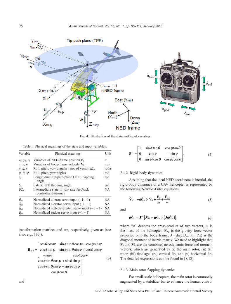
We have obtained a complete flight dynamics model forHeLion in [8] using the first-principles approach. The com-plete structure of the nonlinear model is depicted in Fig. 3,which includes four key components: (i) kinematics; (ii)6-DOF rigid-body dynamics; (iii) main rotor flapping dynam-ics; and (iv) factory-installed yaw rate feedback controllerdynamics. This flight dynamics model features minimumcomplexity and contains fifteen states and four inputs, whichare illustrated in Fig. 4 and summarized in Table I. In themodeling procedure, some unique features of the hobby-based helicopters, such as stabilizer bar configuration andthe yaw rate feedback controller, have been included. Thenecessity has been well proven in some documented work(see, for example, [8,24]).
2.1.1 Kinematics
The Kinematics part includes two equations, whichdescribe the relative motions between the two coordinateframes adopted, i.e., the body frame and the local north-east-down (NED) frame. More specifically, the one relative to thetranslational motion is given by
�P V R Vn n n b b= = , (1)
and the relative rotational motion is expressed by
��
�
φθψ
⎛
⎝
⎜⎜⎜
⎞
⎠
⎟⎟⎟
= −S 1wb nb , (2)
where Pn is the NED-based position vector, Vn is theNED-based velocity vector, Vb is the body-frame velocityvector, wb n
b is the angular rate vector, Rn/b and S are the
Fig. 3. Structure of the HeLion dynamic model.
97G. Cai et al.: UAV Flight Control System Design
© 2012 John Wiley and Sons Asia Pte Ltd and Chinese Automatic Control Society
transformation matrices and are, respectively, given as (seealso, e.g., [30]):
Rn b
cos cos sin sin cos cos sin
cos sin sin sin sin cos=−+
θ ψ φ θ ψ φ ψθ ψ φ θ ψ φ ccos
sin sin cos
cos sin cos sin sin
cos sin sin s
ψθ φ θ
φ θ ψ φ ψφ θ ψ
−
⎡
⎣
⎢⎢⎢
+− iin cos
cos cos
φ ψφ θ
⎤
⎦
⎥⎥⎥
(3)
and
S− = −⎡
⎣
⎢⎢⎢
⎤
⎦
⎥⎥⎥
1
1
0
0
sin tan cos tan
cos sin
sin cos cos cos
φ θ φ θφ φ
φ θ φ θ.. (4)
2.1.2 Rigid-body dynamics
Assuming that the local NED coordinate is inertial, therigid-body dynamics of a UAV helicopter is represented bythe following Newton-Euler equations
�V VF F
b b nb
bb b g= − × + +w
m m,
(5)
and
�w w wb nb
b b nb
b nb= − × ( )[ ]−J M J1 , (6)
where “¥” denotes the cross-product of two vectors, m isthe mass of the helicopter, Fb,g is the gravity force vectorprojected onto the body frame, J = diag{Jxx, Jyy, Jzz} is thediagonal moment of inertia matrix. We need to highlight thatFb and Mb are the combined aerodynamic force and momentvectors, which are generated by (i) the main rotor, (ii) tailrotor, (iii) fuselage, (iv) vertical fin, and (v) horizontal fin.The detailed expressions can be found in [8,18].
2.1.3 Main rotor flapping dynamics
For small-scale helicopters, the main rotor is commonlyaugmented by a stabilizer bar to enhance the human control
Fig. 4. Illustration of the state and input variables.
Table I. Physical meanings of the state and input variables.
Variable Physical meaning Unit
xn, yn, zn Variables of NED-frame position Pn mu, v, w Variables of body-frame velocity Vb m/sp, q, r Roll, pitch, yaw angular rates of vector wb n
b rad/sf, q, y Roll, pitch, yaw angles radas Longitudinal tip-path-plane (TPP) flapping
anglerad
bs Lateral TPP flapping angle radδ ped
int Intermediate state in yaw rate feedbackcontroller dynamics
NA
dlat Normalized aileron servo input (-1 ~ 1) NAdlon Normalized elevator servo input (-1 ~ 1) NAdcol Normalized collective pitch servo input (-1 ~ 1) NAdped Normalized rudder servo input (-1 ~ 1) NA
98 Asian Journal of Control, Vol. 15, No. 1, pp. 95–119, January 2013
© 2012 John Wiley and Sons Asia Pte Ltd and Chinese Automatic Control Society

stability while maintaining the maneuverability. The dynam-ics of the stabilizer bar can be lumped into that of the baremain rotor, and the augmented flapping dynamics can bedescribed by the following two coupled first-order differentialequations:
�a q aA
bA
seff
sb
effs
lon
efflon
s= − − + +1
τ τ τδ (7)
and
�b pB
a bB
sa
effs
effs
lat
efflat
s= − + − +τ τ τ
δ1, (8)
where teff is the effective time constant of the augmentedmain rotor system which counts for the stabilizer bar, Abs andBas are the coupling effect between longitudinal and lateralflapping motions, and Alon and Blat are the effective linkagegains.
2.1.4 Yaw rate feedback controller dynamics
To the human control of the miniature helicopters, ayaw rate feedback controller is required to assist the pilot todeal with the high sensitivity of the bare yaw channeldynamics. This feature is retained when we upgrade a hobbyhelicopter to an UAV system. Considering the feedback con-troller is a PI type, we first define an intermediate statedped,int, which is the integration of the error between theamplified yaw channel input signal and the yaw rate feed-back, with
�δ δped int a ped, ,= −K r (9)
and then express the PI relationship as
δ δ δped P a ped I ped int= −( ) +K K r K , , (10)
where KP and KI are the proportional and integral gains ofthe embedded controller, Ka is the scaling value of theembedded amplifier circuit, and δped is the actual rudderservo actuator deflection for generating the tail rotor forceand moment.
Among the aforementioned ten equations, (1, 2, 5, 6,7, 8, 9) contain the fifteen states listed in Table I and canform a state-space structure. In [8], we have provided adetailed procedure to determine the model parametersof HeLion. The model we have obtained has been provento be highly accurate. We refer interested readers to [8]for the detailed identification procedure and identifiedparameters.
2.2 Inner-loop flight control system
As mentioned earlier, we will adopt the three-layerautomatic flight control system as given in Fig. 1 for ourunmanned vehicles based on the time scales of the statevariables of the helicopter. The detailed structure of the inner-loop layer and the outer-loop layer of our automatic flightcontrol system is depicted in Fig. 5, in which:
1. the inner loop stabilizes the dynamics of the helicopterassociated with its Euler angles f, q, and y, angularvelocities p, q, and r, tip-path-plane (TPP) flappingangles of the main rotor as and bs, and the intermediatestate of the built-in yaw rate feedback controller dped,int;and
2. the outer loop controls the local-NED-based positionsxn, yn, and zn, and their respective velocities un, vn, andwn. Generally, the dynamics associated with the outer-loop layer are much slower compared to those in theinner loop.
In [4], the H• control technique is employed todesign an inner-loop control law for HeLion. In the adoptedthree-layer flight control structure, it turns out that theinner-loop dynamics model is almost invariant with respectto the flight velocities. Here we need to highlight that (i)the invariability of the inner-loop dynamics only holdswhen a miniature rotorcraft performs non-acrobatic maneu-vers (i.e., without drastic changes in attitude dynamics),and (ii) despite the invariance of the parameters of theinner-loop dynamics model, the trimmed values of bothinput and state variables (defined respectively by utrim andxtrim) show a notable change subject to a different flightvelocity. The unified linearized model for the inner loop isgiven by
�x x u win in in in= + +A B E , (11)
where win is the wind gust disturbance, xin = xact - xtrim isthe difference between the actual state variables and theirtrimmed values, and similarly, uin = uact - utrim is thedifference between the actual input variables and theirtrimmed values, and where xact and uact are respectivelygiven as
xact s s ped intT= [ ]φ θ δ ψp q a b r , (12)
and
uact lat lon pedT= [ ]δ δ δ . (13)
Moreover, A, B and E for HeLion are respectively givenby
99G. Cai et al.: UAV Flight Control System Design
© 2012 John Wiley and Sons Asia Pte Ltd and Chinese Automatic Control Society

Fig.
5.D
etai
led
stru
ctur
eof
the
inne
r-lo
opan
dou
ter-
loop
laye
rsof
the
flig
htco
ntro
lsy
stem
.
100 Asian Journal of Control, Vol. 15, No. 1, pp. 95–119, January 2013
© 2012 John Wiley and Sons Asia Pte Ltd and Chinese Automatic Control Society

A =
− − −−
0 0 1 0 0
0 0 0 0 9992 0
0 0 0 0302 0 0056 0 003
0 0 0 0 0707 267 7499
0
.
. . .
. .
00 0 1 0000 3 3607
0 0 1 0 2 4483
0 0 0 0579 0 0108 0 0049
0 0 0 0 0
0 0 0 0
− −−
. .
.
. . .
.00389 0
0 0 0009 0 0
0 0 0389 0 0
585 1165 11 4448 59
⎡
⎣
⎢⎢⎢⎢⎢⎢⎢⎢⎢⎢⎢⎢
−−
.
.
. . .5529 0
0 0003 0 0 0
2 2223 0 0 0
3 3607 0 0 0
0 0037 21 9557 114 2 0
0 1 0
−
−−
−
.
.
.
. . .
00
0 0 9992 0 0.
⎤
⎦
⎥⎥⎥⎥⎥⎥⎥⎥⎥⎥⎥⎥
and
B =−
−
0 0 0
0 0 0
0 0 43 3635
0 0 0
0 2026 2 5878 0
2 5878 0 0663 0
0 0 83 1883
0
.
. .
. .
.
00 3 8500
0 0 0
0 0 0
0 0 0
0 0001 0
−
⎡
⎣
⎢⎢⎢⎢⎢⎢⎢⎢⎢⎢⎢⎢
⎤
⎦
⎥⎥⎥⎥⎥⎥⎥⎥⎥⎥⎥⎥
=
−
.
,
. .
E
11756 0 0395
0 0000 0 0003 0 0338
0 0 0
0 0 0
0 0002 0 3396 0 6424
0 0
−
− −
.
. . .
. . .
00
0 0 0
⎡
⎣
⎢⎢⎢⎢⎢⎢⎢⎢⎢⎢⎢⎢
⎤
⎦
⎥⎥⎥⎥⎥⎥⎥⎥⎥⎥⎥⎥
.
The measurement output is given by
y y= [ ] −φ θ ψp q r Ttrim, (14)
where ytrim is the trim value of the corresponding measur-able state variables. The primary output to be controlled isselected as
h h: ,= [ ] −φ θ ψ Ttrim (15)
where htrim is the trim value of the corresponding h. Underthis problem formulation setting and using the technique forgeneral H• control given in [9], an effective inner-loopcontroller has been obtained and is given as the following:
u x r hin trim= + −( )F Ginˆ , (16)
where r = [fr qr yr]T is the reference signal vector generatedby a command generator linked to the outer-loop control law,
F =− − − − −
− −1 0368 0 0604 0 0230 0 0083 0 2857
0 0760 0 9970 0 0174 0
. . . . .
. . . .. .
. . . . .
.
0378 1 8340
0 0002 0 0185 0 0066 0 0004 0 0353
2 6165
−− − −
⎡
⎣
⎢⎢⎢
− −− −− −
0 0312 0 0499 0 0746
0 1130 0 0026 0 0024 0 0169
0 0990 0 004
. . .
. . . .
. . 44 0 2295 0 2441. .
,⎤
⎦
⎥⎥⎥
G = −−
1 0368 0 0604 0 0746
0 0760 0 9970 0 0169
0 0002 0 0185 0 2441
. . .
. . .
. . .
⎡⎡
⎣
⎢⎢⎢
⎤
⎦
⎥⎥⎥
,
and x̂in is the estimation of the state variable xin. There areonly three state variables, i.e., as, bs and dped,int, that cannot bedirectly measured. The estimation of xin can be done throughthe following reduced-order estimator:
�x x y uin cmp in cmp in cmp in cmp in cmp in, , , , , ,= + +A B H (17)
where
A
H
in cmp
in cmp
,
,
,
. .
.
=−
−−
⎡
⎣
⎢⎢⎢
⎤
⎦
⎥⎥⎥
=
10 0 0
0 10 0
0 0 12
0 2026 2 5878 0
2 58878 0 0663 0
0 0 4 8913
−⎡
⎣
⎢⎢⎢
⎤
⎦
⎥⎥⎥
.
.
,
Bin cmp,
. . .
. .= ×− − −
− − −−10
0 0 3 7980 124 6213 1 9798 0
0 0 111 3469 9 07932 55 9148 0
0 0 0 6076 0 1112 4 6136 0
.
. . .
.
− −
⎡
⎣
⎢⎢⎢
⎤
⎦
⎥⎥⎥
The estimation of the unmeasurable state variables is given by
ˆ
ˆ
ˆ
,
,
, ,
a
b K
s
s
ped int
in cmp in cmp
δ
⎛
⎝
⎜⎜⎜
⎞
⎠
⎟⎟⎟
= +x y (18)
where
101G. Cai et al.: UAV Flight Control System Design
© 2012 John Wiley and Sons Asia Pte Ltd and Chinese Automatic Control Society

Kin cmp,
. . .
. . .= ×−10
0 0 3 7980 24 7966 1 9798 0
0 0 11 3469 9 1439 5 9148 0
0
3
00 0 0 105 0784 0.
.⎡
⎣
⎢⎢⎢
⎤
⎦
⎥⎥⎥
It is shown that the above inner-loop control law is able toachieve the top level performance in all the categories underexamination in accordance with the standards set for militaryrotorcraft by US Army Aviation [2].
III. OUTER-LOOP FLIGHTCONTROL SYSTEM
As mentioned earlier, the outer loop of our proposedautomatic flight control system is for controlling the posi-tion of the unmanned system in the local NED frame. Tra-ditionally, the outer-loop layer can be controlled by simplecontrollers, such as PID or even proportional control laws(see, e.g., [4]). However, the flight control system withsimple outer-loop controllers can only provide reasonableperformance for position and heading control. When itcomes to situations in which complicated maneuvers arerequired, it generally results in poor performance. Wepropose in this chapter the design of the outer-loop control-lers for our unmanned systems using the so-called robustand perfect tracking (RPT) control technique developed byChen and his co-workers (see, e.g., [9,10]). Given a systemthat satisfies certain conditions, the RPT control techniqueis for designing a controller such that the resulting closed-loop system is asymptotically stable and the controlledoutput almost perfectly tracks a given reference signal in thepresence of any initial conditions and external disturbances.Almost perfect tracking means the ability of a controller totrack a given reference signal with an arbitrarily fast settlingtime in the face of external disturbances and initial condi-tions. Of course, in real life, a certain tradeoff has to bemade in order to design a physically implementable controllaw.
We should highlight that one of the most interestingfeatures in the RPT control method is its capability of utiliz-ing all possible information available in its controller struc-ture. More specifically, given a reference, if its derivatives arealso available, all of them can be fed into the RPT controllerto yield a better performance. Such a feature is highly desir-able for flight missions involving complicated maneuvers, inwhich not only the position reference is useful, but also itsvelocity and even acceleration information are important oreven necessary to be used in order to achieve a good overallperformance. As a result, the RPT control renders the flightformation of multiple UAVs a trivial task. In what follows, wefirst recall the basic theory behind the RPT technique. Inter-ested readers are referred to [9] for the rigorous treatment ofthe RPT control theory.
3.1 Robust and perfect tracking control understate feedback
Consider the following continuous-time system:
Σ :
, ( ) ,�x Ax Bu Ew x x
y x
h C x D u
= + + === +
⎧⎨⎪
⎩⎪
0 0
2 2
(19)
where x ∈ Rn is the state, u ∈ Rm is the control input, w ∈ Rq
is the external disturbance, and h ∈ Rl is the output to becontrolled. Given the external disturbance w ∈ Lp, p ∈ [1,•),and any reference signal vector r ∈ Rl with r, �r, . . . , r(k-1),k � 1, being available, and r(k) being either a vector of deltafunctions or in Lp, the RPT problem for the system in (19) isto find a parameterized state feedback control law of thefollowing form:
u F x H r H r= + + + −−( ) ( ) ( ) ( )ε ε εκ
κ0 1
1� (20)
such that when the controller of (20) is applied to the systemof (19), we have the following:
1. There exists an e* > 0 such that the resulting closed-loop system with r = 0 and w = 0 is asymptoticallystable for all e ∈ (0,e*].
2. Let h(t,e) be the closed-loop controlled output responseand let e(t,e) be the resulting tracking error, i.e.,e(t,e):= h(t,e) - r(t). Then, for any initial condition ofthe state, x0 ∈ Rn,
e e t tp
pp
= ( ) → →∞
∫ ( ) .d as0
1
0 0ε (21)
We introduce in the above formulation some additionalinformation besides the reference signal r, i.e., � ��r r, , . . . , r(k-1),as additional controller inputs. In flight control systems,taking r as a position reference, generally, its associatedvelocity, �r, and acceleration, ��r, are readily available. These�r t( ) and ��r t( ) can be used to improve the overall trackingperformance. It was shown in [9] that the RPT problem forthe system in (19) is solvable if and only if (i) (A,B) isstabilizable, and (ii) (A,B,C2,D2) is right invertible and ofminimum phase.
In what follows, we construct a parameterized statefeedback control law as given in (20) that solves the RPTproblem for the system in (19). It is simple to note that we canrewrite the given reference in the following form:
d
dt
r
r
r
I
I
��
� � � ���
�
�( )
( )
κ
κ
−
−
⎛
⎝
⎜⎜⎜⎜
⎞
⎠
⎟⎟⎟⎟
=
⎡
⎣
⎢⎢⎢⎢
⎤
⎦
⎥⎥
2
1
0 0
0 0
0 0 0
⎥⎥⎥
⎛
⎝
⎜⎜⎜⎜
⎞
⎠
⎟⎟⎟⎟
+
⎡
⎣
⎢⎢⎢⎢
⎤
⎦
⎥⎥⎥⎥
−
−
r
r
r I
r� �
�
�
( )
( )
( ).κ
κ
κ2
1
0
(22)
Combining (22) with the given system, we obtain thefollowing augmented system:
102 Asian Journal of Control, Vol. 15, No. 1, pp. 95–119, January 2013
© 2012 John Wiley and Sons Asia Pte Ltd and Chinese Automatic Control Society
ΣAUG :
�x u
e u
= + +== +
⎧⎨⎪
⎩⎪
A B E
C D
x w
y x
x2 2
(23)
where
x
r
r
r
x
w
r: , : ,( )
( )( )
=
⎛
⎝
⎜⎜⎜⎜⎜
⎞
⎠
⎟⎟⎟⎟⎟
= ⎛⎝⎜
⎞⎠⎟
−
−
�κ
κκ
2
1
w (24)
A B=
⎡
⎣
⎢⎢⎢⎢⎢⎢
⎤
⎦
⎥⎥⎥⎥⎥⎥
=
⎡
⎣
⎢⎢⎢
0 0 0
0 0 0
0 0 0 0
0 0 0
0
0
0
I
I
A B
�
�
�� � � � �
���
�,
⎢⎢⎢⎢
⎤
⎦
⎥⎥⎥⎥⎥⎥
=
⎡
⎣
⎢⎢⎢⎢⎢⎢
⎤
⎦
⎥⎥⎥⎥⎥⎥
,
,E
0 0
0 0
0
0
� �
�I
E
(25)
and
C D2 2 2 20 0 0= −[ ] =I C D� � , . (26)
It is then straightforward to show that the subsystem from uto e in the augmented system of (23), i.e., the quadruple(A,B,C2,D2), is right invertible and has the same infinite zerostructure as that of (A,B,C2,D2). Furthermore, its invariantzeros contain those of (A,B,C2,D2) and � ¥ k extra ones ats = 0.
Next, we define
��C
C
D
D
2
2
2
2
0
0 ,=⎡
⎣
⎢⎢⎢
⎤
⎦
⎥⎥⎥
=⎡
⎣
⎢⎢⎢
⎤
⎦
⎥⎥⎥
+εε
κI
In
m
, (27)
��
�
�� � � �
��
�
�
�
A =⎡⎣⎢
⎤⎦⎥ = − +
⎡
⎣
⎢⎢⎢⎢
⎤
⎦
⎥⎥⎥⎥
A
AA I
I
I0
0 0
0
0
0 0
0 0
0 0 0
, ,ε κ (28)
where �0 is a sufficiently small scalar (introduced to fool theRiccati equation), and solve the following Riccati equation:
PA A P C C PB C D D D
PB C D
� � � � � � � �
� �
+ + − +( )( )+( ) =
−T T T T
T T
2 2 2 2 2 21
2 2 0(29)
for a positive-definite solution P > 0. The required statefeedback gain matrix that solves the RPT problem for thegiven system is then given by
� � � � �
�
F D D PB C D( )
( ) ,
2 21
2 2
0 1
εε ε εκ
= −( ) +( )= [ ]
−
−
T T T
H H F( ) ( )(30)
where Hi(e) ∈ Rm¥� and F(e) ∈ Rm¥n.Finally, we note that solutions to the Riccati equation in
(29) might have severe numerical problems as e becomessmaller and smaller. Alternatively, one can solve the RPTcontrol problem using a structural decomposition approach,which can be found in Chen [9].
3.2 Outer-loop control system design
As depicted in Fig. 6, the outer loop of the flight controlsystem is for controlling the position of the unmannedrotorcraft, i.e., Pn. In Fig. 6, the inner-loop command genera-tor is computed as the following:
δφθ
r
r
r
in cl b r
⎛
⎝
⎜⎜
⎞
⎠
⎟⎟
= ( )−G , , , ,01 a (31)
where Gin,cl,0 is the DC gain of the inner closed-loop systemwith its input variables being dr, fr, and qr and its outputvariables being ax, ay, and az, respectively. For HeLion withthe H• inner-loop controller as given in Section 2.2, theresulting DC gain is given by
Gin cl, ,
. . .
. . .
.0
1
0 0001 0 0019 0 0478
0 0022 0 1031 0 0048
0 1022 0 0
− =−
− −..
.
0002
⎡
⎣
⎢⎢⎢
⎤
⎦
⎥⎥⎥
(32)
For the outer-loop control system design, we treat the closedinner-loop and the inner-loop command generator, i.e., theportion inside the dashed box in Fig. 6, as a virtual actuator(such a design idea is illustrated in Fig. 7 for easy reference).Our design will work properly, if an,r with frequencies in theworking range of the outer loop is able to freely pass throughthe virtual actuator. It indeed turns out to be the case.
Shown in Figs 8 and 9 are the frequency responses ofthe linearized model of the virtual actuator, which clearlyindicate that all its three channels are almost perfectly decou-pled. Moreover, the characteristics of both the X- andY-channels are of low-pass systems with cutoff frequenciesaround 1 rad/s, whereas the Z-channel is an all-pass system.As such, it is pretty safe for us to separate the outer rotorcraftdynamics into three decoupled channels, respectively, in theX-, Y-, and Z-axes of the local NED frame, with each channelbeing characterized by a double integrator, provided that theactual working frequency of the outer loop is kept within the
103G. Cai et al.: UAV Flight Control System Design
© 2012 John Wiley and Sons Asia Pte Ltd and Chinese Automatic Control Society

Fig.
6.O
uter
loop
ofth
ero
torc
raft
flig
htco
ntro
lsy
stem
.
104 Asian Journal of Control, Vol. 15, No. 1, pp. 95–119, January 2013
© 2012 John Wiley and Sons Asia Pte Ltd and Chinese Automatic Control Society

bandwidth of the virtual actuator, i.e., 1 rad/s. More specifi-cally, in such a situation, the dynamical equation for theX-axis can be expressed as
��x
u
x
ua
n
n
n
nx n
⎛⎝⎜
⎞⎠⎟
= ⎡⎣⎢
⎤⎦⎥
⎛⎝⎜
⎞⎠⎟
+ ⎡⎣⎢
⎤⎦⎥
0 1
0 0
0
1, , (33)
where xn is the X-axis position of the UAV in the local NEDframe, and un and ax,n are respectively the local NED velocityand acceleration projected onto the X-axis. Similarly, thedynamic equations for the Y- and Z-axes are given by
��y
v
y
va
n
n
n
ny n
⎛⎝⎜
⎞⎠⎟
= ⎡⎣⎢
⎤⎦⎥
⎛⎝⎜
⎞⎠⎟
+ ⎡⎣⎢
⎤⎦⎥
0 1
0 0
0
1, (34)
and
��z
w
z
wa
n
n
n
nz n
⎛⎝⎜
⎞⎠⎟
= ⎡⎣⎢
⎤⎦⎥
⎛⎝⎜
⎞⎠⎟
+ ⎡⎣⎢
⎤⎦⎥
0 1
0 0
0
1, , (35)
respectively, with all of its state and control variables defined inthe same fashion as those in (33). We should note that in theunmanned rotorcraft system, its position, velocity, and accel-eration are all measurable and available for feedback control. Itshould also be noted that the disturbance we intend to reject isthe wind gust. In our work, it only affects the flight dynamicsvia the three body-frame velocity channels. In other words, thedisturbance is only considered in our inner-loop controlsystem design. As a consequence, the outer-layer dynamicsonly consist of above three kinematic relationships along threeNED-frame axes, without considering any disturbance effect.The disturbance term in (19), or equivalently, in (33) to (35), isthus not involved. As all three channels share the samedynamic structure, we proceed in what follows to focus on thedesign of the outer-loop controller for the X-axis only using theRPT control technique introduced in the previous section. Thecontrollers for theY-axis and the heave direction can be carriedout with the same procedure.
To control the position of the UAV, we defined thecontrolled output associated with (33) as
h xx
ux n
n
n
= = [ ]⎛⎝⎜
⎞⎠⎟
1 0 .(36)
It is straightforward to verify that the RPT control problemfor the given system comprising (33) and (36) is solvableunder state feedback. Since the position reference xn,r and itsassociated velocity, un,r, and acceleration, ax,n,r, are allavailable, we formulate the problem into the RPT designframework by defining
d
d
n r
n r
x n r
n r
n r
x n
t
x
u
a
x
u
a
,
,
, ,
,
,
, ,
⎛
⎝
⎜⎜
⎞
⎠
⎟⎟
=⎡
⎣
⎢⎢⎢
⎤
⎦
⎥⎥⎥
0 1 0
0 0 1
0 0 0 rr
x n r
⎛
⎝
⎜⎜
⎞
⎠
⎟⎟
+⎡
⎣
⎢⎢⎢
⎤
⎦
⎥⎥⎥
0
0
1
�a , , . (37)
We obtain an augmented system of the following form:
ΣAUG :
�x x w
y x
x
= + +==
⎧⎨⎪
⎩⎪
A B E
C
u
e 2
(38)
where
x w: , : ,
,
,
, , , ,=
⎛
⎝
⎜⎜⎜⎜⎜
⎞
⎠
⎟⎟⎟⎟⎟
=
x
u
a
x
u
a
n r
n r
x n r
n
n
x n r� (39)
A B=
⎡
⎣
⎢⎢⎢⎢⎢⎢
⎤
⎦
⎥⎥⎥⎥⎥⎥
=
⎡
⎣
⎢⎢⎢⎢⎢
0 1 0 0 0
0 0 1 0 0
0 0 0 0 0
0 0 0 0 1
0 0 0 0 0
0
0
0
0
1
,
⎢⎢
⎤
⎦
⎥⎥⎥⎥⎥⎥
=
⎡
⎣
⎢⎢⎢⎢⎢⎢
⎤
⎦
⎥⎥⎥⎥⎥⎥
, ,E
0
0
1
0
0
(40)
and
Fig. 7. Reconfiguration of the outer-loop flight control system.
105G. Cai et al.: UAV Flight Control System Design
© 2012 John Wiley and Sons Asia Pte Ltd and Chinese Automatic Control Society

Fig. 8. Frequency responses of the main channels of the virtual actuator.
106 Asian Journal of Control, Vol. 15, No. 1, pp. 95–119, January 2013
© 2012 John Wiley and Sons Asia Pte Ltd and Chinese Automatic Control Society

Fig. 9. Magnitude responses of all channels of the virtual actuator.
107G. Cai et al.: UAV Flight Control System Design
© 2012 John Wiley and Sons Asia Pte Ltd and Chinese Automatic Control Society

C2 1 0 0 1 0= −[ ]. (41)
Using the procedure given in [9], we are able to obtain aclosed-form solution for the state feedback gain for thesystem of (38) that solves the RPT control problem. Theclosed-form solution is given by
u = Fx (42)
with
F = − −⎡⎣⎢
⎤⎦⎥
ωε
ζ ωε
ωε
ζ ωε
n x
x
x n x
x
n x
x
x n x
x
, , , ,2
2
2
2
2 21 . (43)
Equivalently, we have
a Fx
uH x H u
H a
x n x xn
nx x n r x x n r
x x x
, , , , ,
,
(= ⎛⎝⎜
⎞⎠⎟
+ +
+
ε ε ε
ε
) ( ) ( )
( )
0 1
2 ,, ,
, , ,,
n r
n x
x
x n x
x
n
n
n x
xn= − ⎡
⎣⎢⎤⎦⎥
⎛⎝⎜
⎞⎠⎟
+ ⎛⎝⎜
⎞⎠⎟
ωε
ζ ωε
ωε
2
2
2
2
2 x
ux rr
x n x
xn r x n r+ ⎛
⎝⎜⎞⎠⎟ +2ζ ω
ε,
, , , ,u a
(44)
where ex is the tuning parameter, and wn,x and zx arerespectively the nominal natural frequency and dampingratio associated with the closed-loop system of the X-axisdynamics. More specifically, the closed-loop eigenvalues ofthe X-axis dynamical system under the state feedback controlare given by
− ± −ζ ωε
ω ζε
x n x
x
n x x
x
, ,j1
.2
(45)
Similarly, following the same procedure, we can obtainthe controllers for the Y-axis dynamics and the heave dynam-ics respectively as
ay
vy
y y yy n
n y y n y n
n
n yn r,
, , ,,= −
⎡
⎣⎢
⎤
⎦⎥
⎛⎝⎜
⎞⎠⎟
+⎛⎝⎜
⎞⎠⎟
ωε
ζ ωε
ωε
2
2
2
2
2
++⎛⎝⎜
⎞⎠⎟
+2ζ ω
εy n y
n r y n r,
, , ,y
v a(46)
and
az
wz
z
z
z zz n
n z n z n
n
n zn r,
, , ,,= − ⎡
⎣⎢⎤⎦⎥
⎛⎝⎜
⎞⎠⎟
+ ⎛⎝⎜
⎞⎠⎟
ωε
ζ ωε
ωε
2
2
2
2
2
++ ⎛⎝⎜
⎞⎠⎟ +2ζ ω
εz
z
w an zn r z n r
,, , , .
(47)
In principle, the RPT controllers above are capable ofachieving an arbitrarily fast response if the tuning parametersare chosen to be sufficiently small. However, we need tofollow several design specifications to account for both the
physical feature of miniature rotorcraft and the feasibility ofpractical implementations. More specifically:
1. The response of the outer-loop system is required to beslower than the bandwidth of the virtual actuator, i.e.,1 rad/s.
2. To minimize overshoots in time-domain responses, thedamping ratios for all these three channels should beselected to be greater than or equal to unity.
3. The closed outer-loop dynamics should have sufficientgain and phase margins.
Based on these guidelines, we finally select the followingouter-loop controller parameters for HeLion:
ω ω ωn x n y n z, , ,. , . , . ,= = =0 54 0 62 0 78 (48)
ε ε εx y z= = =1, (49)
and
ζ ζ ζx y z= = =1 1 1 1, , . . (50)
We note that in order to minimize overshoots in time-domainresponses, the damping ratios for all three channels areselected to be greater than or equal to unity.
In order to the verify the robustness of the outer-loopflight control system, we examine the frequency response ofeach individual channel of the outer-loop system, which arerespectively shown in Figs 10 to 12. It is clear that all thechannels have an infinite gain margin and a phase margingreater than 75 degrees. The overall outer-loop system isrobust enough to handle the external disturbances and uncer-tainties resulting from the virtual actuator of the inner-looplayer.
IV. SIMULATION ANDIMPLEMENTATION RESULTS
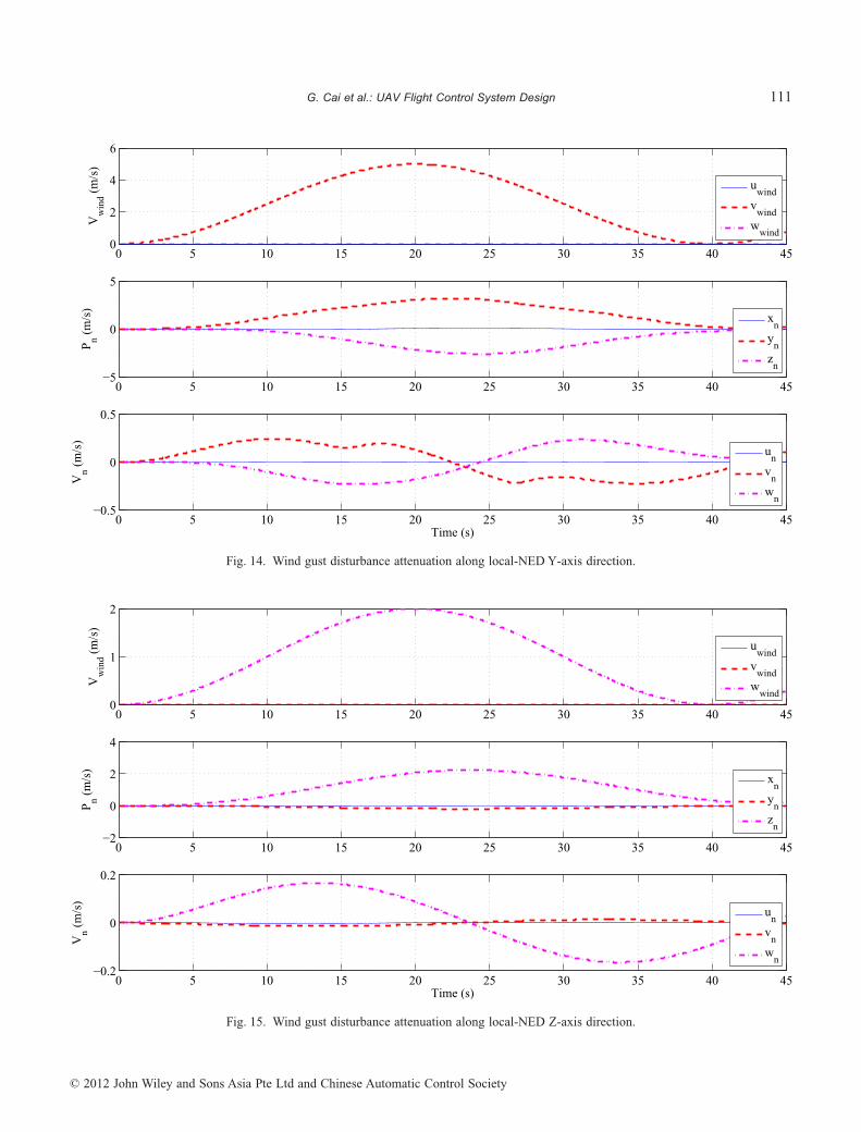
Before conducting actual flight tests, we have carriedout a series of hardware-in-the-loop simulations to evaluateeffectively the reliability and performance of HeLion. Inour proposed hardware-in-the-loop simulation frameworkdetailed in [7], the key components of the unmanned system,including the RC helicopter, the avionic system, and theground control station, are activated to maximally emulateHeLion maneuvering in real flight. As a result, any harmfuldeficiencies or improper designs can be discovered and theprobability of flight accidents can then be minimized. Inthe hardware-in-the-loop simulations, we mainly intend toevaluate the wind gust disturbance attenuation, and thetracking performance of position and velocity. More specifi-cally, Figs 13 to 15 show the position and velocity hold per-formance with the overall system due to a wind gust,
108 Asian Journal of Control, Vol. 15, No. 1, pp. 95–119, January 2013
© 2012 John Wiley and Sons Asia Pte Ltd and Chinese Automatic Control Society

10−2
10−1
100
101
−80
−60
−40
−20
0
20
Mag
nitu
de (
dB)
Gain margin = ∞, Phase margin = 76.3 deg (at 0.042 Hz)
10−2
10−1
100
101
−160
−140
−120
−100
Pha
se (
deg)
Frequency (Hz)
Fig. 10. Gain and phase margins of local NED X-axis position control.
10−2
10−1
100
101
−80
−60
−40
−20
0
20
Mag
nitu
de (
dB)
Gain margin = ∞, Phase margin = 76.3 deg (at 0.048 Hz)
10−2
10−1
100
101
−160
−140
−120
−100
Pha
se (
deg)
Frequency (Hz)
Fig. 11. Gain and phase margins of local NED Y-axis position control.
109G. Cai et al.: UAV Flight Control System Design
© 2012 John Wiley and Sons Asia Pte Ltd and Chinese Automatic Control Society

10−1
100
101
−80
−60
−40
−20
0
Mag
nitu
de (
dB)
Gain margin = ∞, Phase margin = 78.6 deg (at 0.056 Hz)
10−1
100
101
−160
−140
−120
−100
Pha
se (
deg)
Frequency (Hz)
Fig. 12. Gain and phase margins of local NED Z-axis position control.
0 5 10 15 20 25 30 35 40 450
2
4
6
Vw
ind (
m/s
)
uwind
vwind
wwind
0 5 10 15 20 25 30 35 40 45−4
−2
0
2
Pn (
m/s
)
xn
yn
zn
0 5 10 15 20 25 30 35 40 45−0.5
0
0.5
Time (s)
Vn (
m/s
)
un
vn
wn
Fig. 13. Wind gust disturbance attenuation along local-NED X-axis direction.
110 Asian Journal of Control, Vol. 15, No. 1, pp. 95–119, January 2013
© 2012 John Wiley and Sons Asia Pte Ltd and Chinese Automatic Control Society
0 5 10 15 20 25 30 35 40 450
2
4
6
Vw
ind (
m/s
)
uwind
vwind
wwind
0 5 10 15 20 25 30 35 40 45−5
0
5
Pn (
m/s
)
xn
yn
zn
0 5 10 15 20 25 30 35 40 45−0.5
0
0.5
Time (s)
Vn (
m/s
)
un
vn
wn
Fig. 14. Wind gust disturbance attenuation along local-NED Y-axis direction.
0 5 10 15 20 25 30 35 40 450
1
2
Vw
ind (
m/s
)
uwind
vwind
wwind
0 5 10 15 20 25 30 35 40 45−2
0
2
4
Pn (
m/s
)
xn
yn
zn
0 5 10 15 20 25 30 35 40 45−0.2
0
0.2
Time (s)
Vn (
m/s
)
un
vn
wn
Fig. 15. Wind gust disturbance attenuation along local-NED Z-axis direction.
111G. Cai et al.: UAV Flight Control System Design
© 2012 John Wiley and Sons Asia Pte Ltd and Chinese Automatic Control Society

whereas Figs 16 to 18 demonstrate the evaluation results oftracking performance. It is noted that for tracking perform-ance we examine three flight motions. In the first maneuver,HeLion starts with a stable hover with heading to the northdirection, then conducts a forward acceleration to 12 m/s,and finally decelerates to another stable hover. The othertwo maneuvers are similar to the first one, but with theacceleration/deceleration directions being changed to theeast and upward and with the top sideslip and heave speedbeing 6 m/s and 2.5 m/s, respectively. It is clear that theoverall performance is very satisfactory in simulation. Thenmore completed tests on the actual flight implementation canbe conducted.
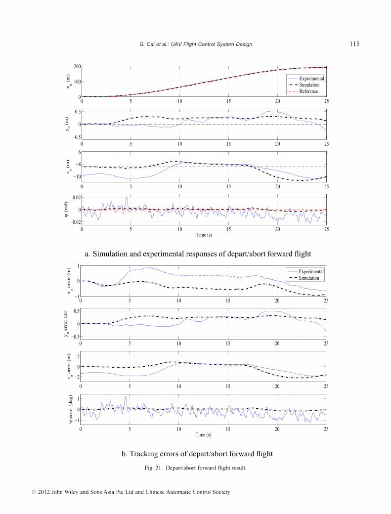
Next, we present the results of the actual flight testexperiments to evaluate the performance of the outer-loopcontrol system using RPT technique. To realize this aim, aseries of mission-task-elements (MTEs), which are origi-nally set in ADS-33D-PRF [2] for evaluating militaryrotorcraft’ performance, have been adopted. More specifi-cally, nine MTEs, including: (i) depart/abort (forwardflight); (ii) hover; (iii) depart/abort (backward flight); (iv)hovering turn; (v) vertical maneuver; (vi) lateral reposition;(vii) turn-to-target; (viii) slalom; and (ix) pirouette, havebeen selected. These MTEs are then concatenated sequen-tially to form an appropriate flight trajectory for the outmostlayer, i.e., the flight scheduling layer, in our proposed flight
control structure (see Fig. 1). The recorded position andvelocity responses are shown from Figs 19 and 20. We needto highlight that:
1. All the nine MTEs have been fully completed in auto-matic control mode.
2. During the flight test, the horizontal wind gust is about4 m/s, which is roughly recorded by handheld anemom-eter. With this disturbance, the predefined flight trajec-tory can still be well maintained.
3. According to the specific requirements on MTEs givenin [2], our RPT-based flight control system can achievethe top-level performance in terms of position andvelocity tracking for each selected MTE. In Tables IIand III together with Figs 21 and 22, we present theevaluation results of two specific cases with the moder-ate aggressiveness (i.e., depart/abort, forward flight,and slalom) for illustration.
4. We have noticed that there are minor gaps between theflight responses and the simulation results. In terms ofposition and velocity, the small differences have theamplitudes of only 2 m and 1 m/s, respectively. Suchinconsistencies are caused by the combination of aseries of factors, including: (i) the slightly remnantwind gust disturbance which cannot be completelyrejected by the inner-loop control system; (ii) the minor
0 2 4 6 8 10 12 14 16 180
20
40
60
80
100
120
x n (m
)
xn
xn, r
0 2 4 6 8 10 12 14 16 180
5
10
15
Time (s)
u n (m
/s)
un
un, r
Fig. 16. Tracking performance evaluation along local NED X-axis direction.
112 Asian Journal of Control, Vol. 15, No. 1, pp. 95–119, January 2013
© 2012 John Wiley and Sons Asia Pte Ltd and Chinese Automatic Control Society

0 2 4 6 8 10 12 14−50
−40
−30
−20
−10
0
y n (m
)
yn
yn, r
0 2 4 6 8 10 12 14−8
−6
−4
−2
0
Time (s)
v n (m
/s)
vn
vn, r
Fig. 17. Tracking performance evaluation along local NED Y-axis direction.
0 0.5 1 1.5 2 2.5 3 3.5 4
−4
−3
−2
−1
0
z n (m
)
zn
zn, r
0 0.5 1 1.5 2 2.5 3 3.5 4−2.5
−2
−1.5
−1
−0.5
0
Time (s)
wn (
m/s
)
wn
wn, r
Fig. 18. Tracking performance evaluation along local NED Z-axis direction.
113G. Cai et al.: UAV Flight Control System Design
© 2012 John Wiley and Sons Asia Pte Ltd and Chinese Automatic Control Society

0 20 40 60 80 100 120 140 160 180 200 220
−15
−10
−5
0
5
10
15
xn (m)
y n (m
)
0 50 100 150 200−14
−12
−10
−8
−6
z n (m
)
Time (s)
ExperimentalSimulationReference
Fig. 19. Position responses of the wide-envelope flight.
0 50 100 150 200 250
−5
0
5
10
15
u n (ra
d/s)
ExperimentalSimulationReference
0 50 100 150 200 250−5
0
5
v n (ra
d/s)
0 50 100 150 200 250
−2
0
2
wn (
rad/
s)
Time (s)
Fig. 20. Velocity responses of the wide-envelope flight.
114 Asian Journal of Control, Vol. 15, No. 1, pp. 95–119, January 2013
© 2012 John Wiley and Sons Asia Pte Ltd and Chinese Automatic Control Society
0 5 10 15 20 250
100
200x
n (
m)
ExperimentalSimulationReference
0 5 10 15 20 25−0.5
0
0.5
yn (
m)
0 5 10 15 20 25
−10
−8
−6
z n (
m)
0 5 10 15 20 25−0.02
0
0.02
ψ (
rad
)
Time (s)
a. Simulation and experimental responses of depart/abort forward flight
0 5 10 15 20 25−1
0
1
xn e
rro
r (m
)
ExperimentalSimulation
0 5 10 15 20 25−0.5
0
0.5
yn e
rro
r (m
)
0 5 10 15 20 25
−2
0
2
z n e
rro
r (m
)
0 5 10 15 20 25
−1
0
1
ψ e
rro
r (d
eg)
Time (s)
b. Tracking errors of depart/abort forward flight
Fig. 21. Depart/abort forward flight result.
115G. Cai et al.: UAV Flight Control System Design
© 2012 John Wiley and Sons Asia Pte Ltd and Chinese Automatic Control Society

195 200 205 210 215 220 225 230 235
50
100
150
200x
n (
m) Experimental
SimulationReference
195 200 205 210 215 220 225 230 235−10
0
10
yn (
m)
195 200 205 210 215 220 225 230 235
−10
−8
−6
z n (
m)
195 200 205 210 215 220 225 230 235−0.04−0.02
00.020.04
ψ (
rad)
Time (s)
a. Simulation and experimental responses of slalom
195 200 205 210 215 220 225 230 235
−1
0
1
xn e
rror
(m) Experimental
Simulation
195 200 205 210 215 220 225 230 235
−1
0
1
yn e
rror
(m)
195 200 205 210 215 220 225 230 235
−2
0
2
z n e
rror
(m)
195 200 205 210 215 220 225 230 235
−2
0
2
ψ e
rror
(deg
)
Time (s)
b. Tracking errors of slalom
Fig. 22. Slalom flight result.
116 Asian Journal of Control, Vol. 15, No. 1, pp. 95–119, January 2013
© 2012 John Wiley and Sons Asia Pte Ltd and Chinese Automatic Control Society

but unavoidable uncertainty of the flight dynamicsmodel; and (iii) other minor environmental disturbancesin the flight experiments.
The results obtained clearly indicate that our controlsystem design using the RPT technique is very successful.The unmanned rotorcraft system is capable of achieving thedesired performance in accordance with the military standardunder examination. Interested readers can access the videoclips of the actual flight tests on our UAV research groupwebsite at http://uav.ece.nus.edu.sg.
V. CONCLUSION
We have presented in this paper a flight controlsystem design, more specifically, the design of the outer-loop layer of the flight control system, using the robust andperfect tracking control technique. The simulation andactual implementation results have shown that the overalldesign is very satisfactory and is capable of achievingthe top level performance in accordance with the standardsset for military rotorcraft by US Army Aviation [2].The unique feature of the RPT control can also be adoptedfor realizing the flight formation of multiple aerialvehicles.
REFERENCES
1. Abbeel, P., A. Coates, and A. Y. Ng, “Autonomous Heli-copter Aerobatics through Apprenticeship Learning,” Int.J. Robot. Res., Vol. 29, No. 13, pp. 1608–1631 (2010).
2. ADS-33D-PRF, Aeronautical design standard perform-ance specification handling qualities requirements formilitary rotorcraft, U.S. Army Aviation and TroopCommand, Redstone Arsenal, Alabama (1996).
3. Bogdanov, A. and E. Wan, “SDRE control with nonlinearfeed forward compensation for a small unmanned heli-copter,” Proc. 2nd AIAA Unmanned Unlimited Syst.,Technol., Oper. Conf., San Diego, CA, AIAA-2003-6512(2003).
4. Cai, G., B. M. Chen, and T. H. Lee, “Design and imple-mentation of robust automatic flight control system for asmall-scale UAV helicopter,” Proc. 7th Asian Control.Conf., Hong Kong, China, pp. 691–697 (2009).
5. Cai, G., B. M. Chen, and T. H. Lee, Unmanned RotorcraftSystems, Springer, New York, NY, (2011).
6. Cai, G., F. Lin, B. M. Chen, and T.H. Lee, “Systematicdesign methodology and construction of UAV helicop-ters,” Mechatron, Vol. 18, No. 10, pp. 545–558 (2008).
7. Cai, G., B. M. Chen, T. H. Lee, and M. Dong, “Designand implementation of a hardware-in-the-loop simula-tion system for small-scale UAV helicopters,” Mecha-tron, Vol. 19, No. 7, pp. 1057–1066 (2009).
8. Cai, G., B. M. Chen, T. H. Lee, and K. Y. Lum, “Com-prehensive nonlinear modeling of an unmanned aerialvehicle helicopter,” Proc. 2008 AIAA Guidance, Naviga-tion and Control Conf., Honolulu, HI, AIAA-2008-7414(2008).
9. Chen, B. M., Robust and H8 Control, Springer, NewYork, NY, (2000).
10. Chen, B. M., Z. Lin, and K. Liu, “Robust and perfecttracking of discrete-time systems,” Automatica, Vol. 38,No. 2, pp. 293–299 (2002).
11. Corban, J. E., A. J. Calise, and J. V. R. Prasad, “Imple-mentation of adaptive nonlinear controller for flight teston an unmanned helicopter,” Proc. 37th IEEE Conf. Dec.Control, Tampa, FL, pp. 3641–3646 (1998).
12. Draganflyer X4 quadrotor helicopter, http://www.draganfly.com/ (2011).
13. Efe, M. O., “Battery power loss compensated fractionalorder sliding mode control of a quadrotor UAV,” Asian J.Control, doi: 10.1002/asjc.340 (2012).
14. Enns, R. and J. Si, “Helicopter flight control designusing a learning control approach,” Proc. 39th IEEEConf. Dec. Control, Sydney, Australia, pp. 1754–1759(2000).
15. Enns, R. and J. Si, “Helicopter trimming and trackingcontrol using direct neural dynamic programming,”IEEE Trans. Neural Netw., Vol. 14, No. 4, pp. 929–939(2003).
16. Fujiwara, D., J. Shin, K. Hazawa, and K. Nonami, “H8
hovering and guidance control for autonomous small-scale unmanned helicopter,” Proc. IEEE/RSJ Int. Conf.Intell Robot. Syst., Sendai, Japan, pp. 2463–2468 (2004).
Table II. Depart/abort (forward flight) performance evaluation.
Specifications Desired level Simulation Actual test
Longitudinal positionerror
�3 m �0.93 m �0.88 m
Lateral position error �3 m �0.31 m �0.51 mAltitude error �3 m �2.16 m �1.85 mHeading error �10° �0.14° �1.24°Time to complete the
maneuver�25 s 25 s 25 s
Table III. Slalom performance evaluation.
Specifications Desired level Simulation Actual test
Maintaining forwardspeed
�6 m/s 6 m/s 6 m/s
Longitudinal positionerror
�2 m �0.56 m �1.41 m
Lateral position error �2 m �1.05 m �1.06 mAltitude error �3 m �1.73 m �2.33 mHeading error �10° �0.18° �2.54°
117G. Cai et al.: UAV Flight Control System Design
© 2012 John Wiley and Sons Asia Pte Ltd and Chinese Automatic Control Society

17. Gadewadikar, J., F. L. Lewis, K. Subbarao, and B. M.Chen, “Structured H8 command and control loop designfor unmanned helicopters,” AIAA J. Guid., Control Dyn.,Vol. 31, No. 4, pp. 1093–1102 (2008).
18. Heffley, R. K. and M. A. Mnich, Minimum-complexityHelicopter Simulation Math Model, Technical ReportNASA Contractor Report 177476, NASA (1988).
19. Isidori, A., L. Marconi, and A. Serrani, “Robust nonlin-ear motion control of a helicopter,” IEEE Trans. Autom.Control, Vol. 48, No. 3, pp. 413–426 (2003).
20. Kadmiry, B., Fuzzy Control for an Autonomous Helicop-ter, M.Sc. Thesis, Linkoping University, Sweden (2002).
21. Koo, T. J. and S. Sastry, “Output tracking control designof a helicopter model based on approximate lineariza-tion,” Proc. 37th IEEE Conf. Dec. Control, Tampa, FL,pp. 3635–3640 (1998).
22. Lee, C.-T. and C.-C. Tsai, “Adaptive backstepping inte-gral control of a small-scale helicopter for airdrop mis-sions,” Asian J. Control, Vol. 12, No. 4, pp. 531–541(2010).
23. Mellinger, D., N. Michael, and V. Kumar, “Trajectorygeneration and control for precise aggressive maneuverswith quadrotors,” Int. Symposium on ExperimentalRobotics, New Delhi, India (2010).
24. Mettler, B. M., Identification, Modeling and Character-istics of Miniature Rotorcraft, Kluwer AcademicPublishers, Boston, MA, (2002).
25. Peng, K., G. Cai, B. M. Chen, M. Dong, K. Y. Lum,and T. H. Lee, “Design and implementation ofan autonomous flight control law for a UAVhelicopter,” Automatica Vol. 45, No. 10, pp. 2333–2338(2009).
26. Shakernia, O., Y. Ma, T. J. Koo, and S. Sastry, “Landingan unmanned air vehicle: vision based motion estimationand nonlinear control,” Asian J. Control, Vol. 1, No. 3,pp. 128–145 (1999).
27. Shim, D. H., H. J. Kim, and S. Sastry, “Control systemdesign for rotorcraft-based unmanned aerial vehicleusing time-domain system identification,” Proc. IEEEConf. Control Appl., Anchorage, AK, pp. 808–813(2000).
28. Shim, D. H., H. J. Kim, and S. Sastry, “Decentralizednonlinear model predictive control of multiple flyingrobots,” Proc. 42nd IEEE Conf. Dec. Control, Maui, HI,pp. 3621–3626 (2003).
29. Sky Surveyor UAV helicopters, http://me2.tm.chiba-u.jp/uav/main/ (2011).
30. Stevens, B. L. and F. L. Lewis, Aircraft Control andSimulation, 2nd ed. John Wiley, Hoboken, NJ, (2003).
31. Sugeno, M., I. Hirano, S. Nakamura, and S. Kotsu,“Development of an intelligent unmanned helicopter,”Proc. 1995 IEEE Int. Conf. Fuzzy Syst., Yokohama,Japan, pp. 33–34 (1995).
32. Wan, E. A. and A. A. Bogdanov, “Model predictiveneural control with applications to a 6 DoF helicoptermodel,” Proc. 2001 Amer. Control Conf., Arlington, VA,pp. 488–493 (2001).
33. Weilenmann, M. W., U. Christen, and H. P. Geering,“Robust helicopter position control at hover,” Proc. Amer.Control Conf., Baltimore, MD, pp. 2491–2495 (1994).
34. Weilenmann, M. W. and H. P. Geering, “Test bench forrotorcraft hover control,” J. Guid., Control Dyn. Vol. 17,No. 4, pp. 729–736 (1994).
Guowei Cai received his B.E. degree inElectrical and Electronics Engineeringfrom Tianjin University, Tianjin, China, in2002, and his Ph.D. degree in Electrical andComputer Engineering from National Uni-versity of Singapore, Singapore, in 2009.From 2008 to 2009, he was a researchfellow in Department of Electrical and
Computer Engineering, National University of Singapore,Singapore. Since 2009, he has been a research scientist in Te-masek Laboratories, National University of Singapore. Hisresearch focuses are miniature fixed-wing or rotorcraftunmanned aerial systems. He was a recipient of the BestApplication Paper Prize at the 7th Asian Control Conference,Hong Kong, China (2009).
Biao Wang received his Bachelor degree inAero-engine Control, Master degree inAero Engines, and Ph.D. degree in Guid-ance, Navigation and Control, all fromNanjing University of Aeronautics andAstronautics, China, in 1997, 2000, and2004, respectively. He is currently Associ-ate Professor in Department of Automatic
Control, Nanjing University of Aeronautics and Astronautics,and a visiting research fellow in Department of Electrical andComputer Engineering, National University of Singapore.
Dr Wang’s current research interests are in the areas oflinear systems, robust and optimal control, flight control andsimulation, computer vision, and unmanned aerial vehicles.
Ben M. Chen received his B.S. degree inMathematics and Computer Science fromXiamen University, China, in 1983, M.S.degree in Electrical Engineering fromGonzaga University, USA, in 1988, andPh.D. degree in Electrical and ComputerEngineering from Washington State Uni-
versity, USA, in 1991. He was a software engineer in South-China Computer Corporation, Guangzhou, China, from 1983to 1986, and was Assistant Professor from 1992 to 1993 inDepartment of Electrical Engineering, State University of
118 Asian Journal of Control, Vol. 15, No. 1, pp. 95–119, January 2013
© 2012 John Wiley and Sons Asia Pte Ltd and Chinese Automatic Control Society

New York at Stony Brook, USA. Since August 1993, he hasbeen with Department of Electrical and Computer Engineer-ing, National University of Singapore, where he is currently aProfessor. His current research interests are in robust control,systems theory, unmanned systems and financial marketmodeling.
He is the author/co-author of 8 research monographsincluding H2 Optimal Control (London: Prentice Hall, 1995);H• Control and Its Applications (New York: Springer, 1998,Chinese edition published by Science Press, Beijing, 2010);Robust and H• Control (New York: Springer, 2000); LinearSystems Theory (Boston: Birkhauser, 2004; Chinese transla-tion published by Tsinghua University Press, 2008); HardDisk Drive Servo Systems (New York: Springer, 1st Edition,2002; 2nd Edition, 2006); and Unmanned Rotorcraft Systems(New York: Springer, 2011). He served/serves on the editorialboards for a number of international journals including IEEETransactions on Automatic Control, Automatica, Systems &Control Letters, Asian Journal of Control, and Journal ofControl Theory and Applications.
Dr Chen is a Fellow of IEEE. He was the recipient ofBest Poster Paper Award, 2nd Asian Control Conference,Seoul, Korea (1997); University Researcher Award, NationalUniversity of Singapore (2000); Prestigious EngineeringAchievement Award, Institution of Engineers, Singapore(2001); Temasek Young Investigator Award, Defence Science& Technology Agency, Singapore (2003); Best IndustrialControl Application Prize, 5th Asian Control Conference,Melbourne, Australia (2004); Best Application Paper Award,7th Asian Control Conference, Hong Kong (2009); and BestApplication Paper Award, 8th World Congress on IntelligentControl and Automation, Jinan, China (2010).
T. H. Lee received B.A. degree with FirstClass Honors in Engineering Tripos fromCambridge University, England, in 1980;and Ph.D. degree from Yale University in1987. He is Professor in the Department ofElectrical and Computer Engineering atNational University of Singapore (NUS);and also Professor in NUS GraduateSchool, NUS NGS. He was Past Vice-
President (Research) of NUS.
Dr Lee’s research interests are in areas of adaptivesystems, knowledge-based control, intelligent mechatronicsand computational intelligence. He currently holds AssociateEditor appointments in IEEE Transactions in Systems, Manand Cybernetics; IEEE Transactions in Industrial Electron-ics; Control Engineering Practice (an IFAC journal); and theInternational Journal of Systems Science (Taylor and Francis,London). In addition, he is Deputy Editor-in-Chief of theIFAC Mechatronics journal.
Dr Lee was a recipient of Cambridge UniversityCharles Baker Prize in Engineering; the 2004 ASCC (Mel-bourne) Best Industrial Control Application Paper Prize;2009 IEEE ICMA Best Paper in Automation Prize; and 2009ASCC Best Application Paper Prize. He has also co-authoredfive research monographs (books), and holds four patents(two of which are in the technology area of adaptive systems,and the other two are in the area of intelligent mechatronics).He has published more than 300 international journal papers.
Dr Lee was Invited Panelist at the World AutomationCongress, WAC2000 Maui USA; Invited Keynote Speakerfor IEEE International Symposium on Intelligent Control,IEEE ISIC 2003 Houston USA; Invited Keynote Speaker forLSMS 2007, Shanghai China; Invited Expert Panelist forIEEE AIM2009; Invited Plenary Speaker for IASTED RTA2009, Beijing China; Invited Keynote Speaker for LSMS2010, Shanghai China; and Invited Keynote Speaker forIASTED CA 2010, Banff Canada.
119G. Cai et al.: UAV Flight Control System Design
© 2012 John Wiley and Sons Asia Pte Ltd and Chinese Automatic Control Society