Design and Fabrication of A Steering Controlled Headlights ... · PDF fileProject Aim is to...
5
Volume No: 2 (2015), Issue No: 7 (July) July 2015 www.ijmetmr.com Page 98 ISSN No: 2348-4845 International Journal & Magazine of Engineering, Technology, Management and Research A Peer Reviewed Open Access International Journal of an automobile operable to maintain headlight mem- bers and front wheels pointed in the same direction at all times. Table 1:Nnumber of road accidents and num- ber of persons involved: 2002 to 2011 2. AIM: Project Aim is to design and fabricate a simple steer- ing controlled head light system, this device relates to a headlight arrangement operably connected to the steering and front wheel assembly of an automobile operable to maintain headlight members and the front wheels pointed in the same direction at all times and it should be an effective replacement for existing con- ventional methods. If we steer the vehicle in right direc- tion, the headlights will also focus to the right. Similarly if we steer vehicle towards left the headlights focus to left with respect to the rack and pinion mechanism. 3. LITERATURE SURVEY: Thomas Hohmann, Jr. in his journal “Rotatable vehicle headlights” (20 July, 1982) described that this invention relates to vehicle headlights which rotate to align the light beam with the direction of the vehicle’s wheels. When a vehicle is travelling a sharp curve or turning a corner, the light beam of a fixedly secured headlight does not illuminate the path over which the vehicle’s ABSTRACT: Special safety features have been built into cars for years, some for the safety of car’s occupants only, and some for the safety of others. One of the choices avail- able is Design and fabrication of steering controlled head light system. Car safety is the avoidance of au- tomobile accidents or the minimization of harmful ef- fects of accidents, in particular as pertaining to human life and health. Still, more specially, this device relates to a headlight arrangement operably connected to the steering and front wheel assembly of and automobile operably to maintain headlight members and the front wheels pointed in the same direction at all times. 1. Introduction: Car safety is the avoidance of automobile accidents or the minimization of harmful effects of accidents, in particular as pertaining to human life and health. Spe- cial safety features have been built into cars for years, some for the safety of car’s occupants only, and some of the safety of others. One of the choices available is Design and fabrication of steering controlled head light system. This device relates to a headlight arrangement for vehicles, and, more particularly, to a head light ar- rangement operably connected to the steering mecha- nism of the vehicle for illuminating the proposed path of travel including support brackets operable to sup- port head light members thereon connectable to a frame portion of the vehicle, linkage means intercon- necting the brackets for conjoint movement thereof, and means interconnecting one of the brackets to the connector rod of the vehicle whereupon the brackets and headlight members are moved in relation to the direction of vehicle travel. Still, more specifically, this device relates to a headlight arrangement operably connected to the steering and front wheel assembly Design and Fabrication of A Steering Controlled Headlights in Automobile B.Anil Kumar Student, Dept of Mechanical Engineering, VITS College of Engineering, Sontyam, Anandapuram, Vizag. N.Laxmi Assistant Professor, Dept of Mechanical Engineering, VITS College of Engineering, Sontyam, Anandapuram, Vizag. D.kiran varma Student, Dept of Mechanical Engineering, VITS College of Engineering, Sontyam, Anandapuram, Vizag.
Transcript of Design and Fabrication of A Steering Controlled Headlights ... · PDF fileProject Aim is to...
Volume No: 2 (2015), Issue No: 7 (July) July 2015 www.ijmetmr.com Page 98
ISSN No: 2348-4845International Journal & Magazine of Engineering,
Technology, Management and ResearchA Peer Reviewed Open Access International Journal
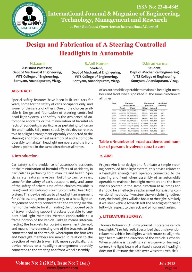
of an automobile operable to maintain headlight mem-bers and front wheels pointed in the same direction at all times.
Table 1:Nnumber of road accidents and num-ber of persons involved: 2002 to 2011
2. AIM:
Project Aim is to design and fabricate a simple steer-ing controlled head light system, this device relates to a headlight arrangement operably connected to the steering and front wheel assembly of an automobile operable to maintain headlight members and the front wheels pointed in the same direction at all times and it should be an effective replacement for existing con-ventional methods. If we steer the vehicle in right direc-tion, the headlights will also focus to the right. Similarly if we steer vehicle towards left the headlights focus to left with respect to the rack and pinion mechanism.
3. LITERATURE SURVEY:
Thomas Hohmann, Jr. in his journal “Rotatable vehicle headlights” (20 July, 1982) described that this invention relates to vehicle headlights which rotate to align the light beam with the direction of the vehicle’s wheels. When a vehicle is travelling a sharp curve or turning a corner, the light beam of a fixedly secured headlight does not illuminate the path over which the vehicle’s
ABSTRACT: Special safety features have been built into cars for years, some for the safety of car’s occupants only, and some for the safety of others. One of the choices avail-able is Design and fabrication of steering controlled head light system. Car safety is the avoidance of au-tomobile accidents or the minimization of harmful ef-fects of accidents, in particular as pertaining to human life and health. Still, more specially, this device relates to a headlight arrangement operably connected to the steering and front wheel assembly of and automobile operably to maintain headlight members and the front wheels pointed in the same direction at all times.
1. Introduction: Car safety is the avoidance of automobile accidents or the minimization of harmful effects of accidents, in particular as pertaining to human life and health. Spe-cial safety features have been built into cars for years, some for the safety of car’s occupants only, and some of the safety of others. One of the choices available is Design and fabrication of steering controlled head light system. This device relates to a headlight arrangement for vehicles, and, more particularly, to a head light ar-rangement operably connected to the steering mecha-nism of the vehicle for illuminating the proposed path of travel including support brackets operable to sup-port head light members thereon connectable to a frame portion of the vehicle, linkage means intercon-necting the brackets for conjoint movement thereof, and means interconnecting one of the brackets to the connector rod of the vehicle whereupon the brackets and headlight members are moved in relation to the direction of vehicle travel. Still, more specifically, this device relates to a headlight arrangement operably connected to the steering and front wheel assembly
Design and Fabrication of A Steering Controlled Headlights in Automobile
B.Anil Kumar Student,
Dept of Mechanical Engineering,VITS College of Engineering,
Sontyam, Anandapuram, Vizag.
N.Laxmi Assistant Professor,
Dept of Mechanical Engineering,VITS College of Engineering,
Sontyam, Anandapuram, Vizag.
D.kiran varmaStudent,
Dept of Mechanical Engineering,VITS College of Engineering,
Sontyam, Anandapuram, Vizag.

Volume No: 2 (2015), Issue No: 7 (July) July 2015 www.ijmetmr.com Page 99
ISSN No: 2348-4845International Journal & Magazine of Engineering,
Technology, Management and ResearchA Peer Reviewed Open Access International Journal
•To provide the nation with an accident free roads.
•To manufacture a Low Cost Automation Project.
6.CALCULATIONS:
Let,Rs = Radius of steering wheel,Rp = Radius of pinion pitch circle,T = No. of teeth on pinion,P = Circular pitch of the pinionFor one revolution of the steering wheel, the input movement at the steering wheel, Xo = 2 * (22/7) * RsTherefore,And the output movement at the rack, Xi = 2×π× Rp =T×PMovement ratio = MR = Xi/Xo = (2×π ×Rp) / (2×π×Rs) = Rs/Rp Also, MR= 2 ×π× Rs / T× P If there is no friction in the gears, MR= output load at the rack / input effort at the steer-ing wheel = W/E7.DETERMINATION OF PITCH CIRCLE DIAM-ETER OF THE PINION:
Let, Radius of pinion pitch circle = Rp Rs = Radius of the steering wheel = 150 mm Movement ratio = MR = Rs / Rp = 150 / RpAlso, Output Resistance of the rack, W = 1000 NAnd Input Effort of steering wheel, E= 50N Therefore, MR = 150 / Rp = 1000 / 50 Hence, Rp = 7.5 mm i.e. Pitch circle diameter of pinion = Rp = 15 mm
8. IDENTIFICATION ANDSELECTION OF SUIT-ABLE MACHINE COMPONENTS:Rack and pinion steering system:
The rack-and-pinion steering box has a pinion, con-nected to the steering column. This pinion runs in mesh with a rack that is connected to the steering tie rods.
wheels are travelling thereby restricting the driver’s visibility. This invention overcomes that defect. Chion-Dong Lin in his journal “Steering wheel controlled car light piloting system” (16 May 1995) described a steer-ing wheel controlled car light piloting system including a motor drive controlled by a control circuit linked to the steering column of the steering wheel of a motor car to turn the lights of the motor car through a trans-mission mechanism consisted of hydraulic cylinders, so as to coincide the positions of the lights of the motor car with the steering direction.
Fig: Adaptive headlights are available on the new
BMW models
You round curve at night and a small `animal jumps in front of you of the darkness. If you had been able to see it, you might have been able to avoid it. What would have helped are headlights that turn when care turns, like BMW’s Adaptive Headlights.The adaptive head-lights use a variable headlight control system geared to the driver’s position on the road. This anticipative illumination of the road ahead is based on a system of sensors and computers.
4. PROBLEMN DEFINITION:Problem: In the Indian context in particular, accidents are in a particular rise at places like steep turnings and curves especially in four wheelers and heavy vehicles like lor-ry’s and busses during the night time. In a way to have a financially viable solution to reduce these accidents, an attempt has been made to design and fabricate a mechanism to increase the visibility of the path for ve-hicle driver during night driving.
5. OBJECTIVE:
•To provide smooth and safety ride in curved roads es-pecially in mountains
•To provide mind free ride for the motorist.

Volume No: 2 (2015), Issue No: 7 (July) July 2015 www.ijmetmr.com Page 100
ISSN No: 2348-4845International Journal & Magazine of Engineering,
Technology, Management and ResearchA Peer Reviewed Open Access International Journal
Four bar mechanism: A four bar mechanism consists of four rigid link which are linked in the form of quadrilateral by four pin joints. A link that makes complete revolution is called crank, the link opposite to the fixed link is the coupler and forth link is a lever or rocker. From the four bar mech-anism, different versions of each of them can be ob-tained by fixing any one of the link.
Fig : General four Bar Linkage Typical terminology for a four bar linkage lables link 1 as the input link, link 2 as the coupler and link 3 as the output link. Of course , link 3 could just as easily be the input link. A four bar linkage is described by the two constraint equations.
These equations use the parameter definitions shown in figure. These constraint equations state that the sum of distances in x-direction and the sum of distances in the y-direction around the four bar linkage must be zero.
10.FABRICATION AND ASSEMBLY Assembly Of Frame To accommodate the various parts firmly to the frame, it is made some adjustments in order to get sufficient weight balance. The final assembly of frame is as shown
Fig : Frame
Fig .Steering gear box
The rack-and-pinion steering gear box has a pinion, connected to the steering column. This pinion runs with a rack that is connected to the steering tie rods. This gives a direct operation. The primary components of the rack and pinion steering system are:
•Rubber Bellows•Pinion•Rack•Inner ball joint or socket•Tie-rod
9. MECHANISMS INVOLVED IN MOTION TRANSFORMATION:A mechanism is a group of links interacting with each other through joints to complete required motion or force transmission.
•Linkage mechanism•Four bar mechanism
Linkage mechanism:
A mechanical linkage is an assembly of bodies connect-ed to manage forces and movement. The movement of a body or a link, is studied using geometry so the link is considered to be rigid. The connections between links are modeled as providing ideal movement, pure rotation or sliding for example, and are called joints. A linkage modeled as a network of rigid links and ideal joints is called a kinematic chain.
Fig: Linkage mechanism
Volume No: 2 (2015), Issue No: 7 (July) July 2015 www.ijmetmr.com Page 101
ISSN No: 2348-4845International Journal & Magazine of Engineering,
Technology, Management and ResearchA Peer Reviewed Open Access International Journal
Arrangement Of Head Light Mechanism:
The head lights are mounted on a bar whose one end is fixed to a board and the other end is connected to a moving bar which is fixed to a special linkage connect-ed to a rack and pinion mechanism.
Fig : Head light attached to frameA horizontal bar made of steel as shown in fig6.4 is fixed in between the two frames and a linkage mecha-nism is connected to the extension of linkages of a rack and pinion mechanism. This mechanism moves in ac-cordance to the rotator motion of steering.
Fig : links attached to the steering mechanism and frame
The two attachments are linked with each other through a rectangular bar having two slots at both the ends. This bar is fixed at the centre to provide a to and fro motion
FINAL ASSEMBLED VIEW:
Fig : Final assembled view
Mounting Of Wheel Drums and Wheels : Wheel drums are installed on a set of bearings fitted to the front axle designed. A set of two wheel drums are used. To this wheel drums a set of two wheels are tightened with nuts.
Fig : Wheel Drums and Wheels
Mounting Of Steering Mechanism and Steer-ing Wheels: The steering wheel is mounted on the frame and the Tie-rods are attached to the wheel drums. The steering wheel is supported by a rod which is welded to the base.
Fig : Steering Wheel The steering wheel is attached to the steering mecha-nism through a steering column. Observe that accurate steering ratios are achieved i.e, between 16:1 to 20:1.
Arrangement Of Head Light Mechanism:
The head lights are mounted on a bar whose one end is fixed to a board and the other end is connected to a moving bar which is fixed to a special linkage connect-ed to a rack and pinion
Fig : Steering Wheel
The steering wheel is attached to the steering mecha-nism through a steering column. Observe that accurate steering ratios are achieved i.e, between 16:1 to 20:1.

Volume No: 2 (2015), Issue No: 7 (July) July 2015 www.ijmetmr.com Page 102
ISSN No: 2348-4845International Journal & Magazine of Engineering,
Technology, Management and ResearchA Peer Reviewed Open Access International Journal
So there by making such movable vehicle head lamps which are economically low to available to the public.
13.REFERANCES:
1.TIEN-Ching Wu: Automatic turning head light structure:Patent no. US6309089 B1, 30 oct 2001
2.Michael J.Barnes and Speak; Adjustable headlight, headlight adjusting and direction sensing control sys-tem and method of adjusting head lights ; patent no; US5868488 A, 9 feb 1999.
3.Chian-yin Tseng; Direction adjustable device for an au-tomobile with a steering linkage: Patent no. US6767119 B2, 27 jul 2004.
4.Chion-Dong Lin; steering wheel controlled car light piloting system, Patent no. US5416465 A; 16 may 1995.
5.Jean Cadiou; steering responsive control device for turning automotive headlamps;Patent no.US3947680 A, 30 mar 1976.
6.Fundamentals of motor vehicle technology by V.A.W.Hiller, 4th edition, Pub: 2009, pg.no.313-336.
7.Automobile engineering by Dr.kirpal singh vol 1, pub; 2010, chapter: front axle steering systems.
8.Automobile engineering by K.K.jain and R.B.Asthana, pub.2006.
9.Automotice mechanics by Willium H Crouse & Donald L Anglin. Pub.2007, part8 chapter 50.
10.www.theautomotive.com
11.RESULTS: We observed that when the steering wheel is rotated through a certain angle towards right side of the driv-er, the head lights are tilted through certain angle be-tween 0-20 degrees to the right with the help of dif-ferent linkages arranged with respect to the steering wheel which were discussed earlier. The same features are observed when the steering wheel is turned to the left side.The results that we have achieve with mechan-ically actuated steering controlled head lights is pictori-ally represented as shown in figures.
Fig: Before & After installing the mechanism.
The representation of the mechanism when installed in a vehicle can be observed in motion as follows:
Fig: Representation of a vehicle in motion with mech-
anism installed12.CONCLUSION:
In the view of forgoing disadvantages inherent in the known types of road tracking headlamps now pres-ent in the prior art, the present invention provides a new movable vehicle head light construction wherein the same can be utilized for automatically aiming the head lamps in the same direction of the travel regard-less of the terrain of the road. The further object of the system is, this is susceptible of a low cost of manufac-turing with regard to both cost and labor and which accordingly is then susceptible of low prices of sale to the public.
Volume No: 2 (2015), Issue No: 7 (July) July 2015 www.ijmetmr.com Page 103
ISSN No: 2348-4845International Journal & Magazine of Engineering,
Technology, Management and ResearchA Peer Reviewed Open Access International Journal