Design and Evaluation of the LOPES Exoskeleton Robot for Interactive Gait Rehabilitation
8
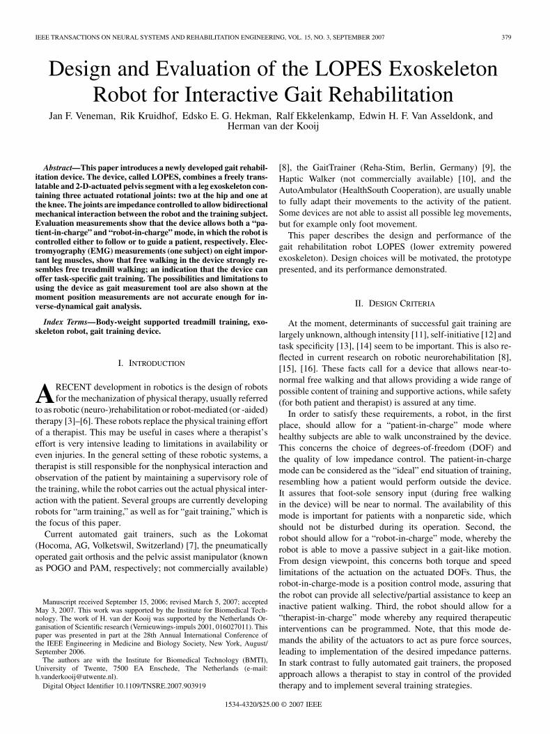
IEEE TRANSACTIONS ON NEURAL SYSTEMS AND REHABILITATION ENGINEERING, VOL. 15, NO. 3, SEPTEMBER 2007 379 Design and Evaluation of the LOPES Exoskeleton Robot for Interactive Gait Rehabilitation Jan F. Veneman, Rik Kruidhof, Edsko E. G. Hekman, Ralf Ekkelenkamp, Edwin H. F. Van Asseldonk, and Herman van der Kooij Abstract—This paper introduces a newly developed gait rehabil- itation device. The device, called LOPES, combines a freely trans- latable and 2-D-actuated pelvis segment with a leg exoskeleton con- taining three actuated rotational joints: two at the hip and one at the knee. The joints are impedance controlled to allow bidirectional mechanical interaction between the robot and the training subject. Evaluation measurements show that the device allows both a “pa- tient-in-charge” and “robot-in-charge” mode, in which the robot is controlled either to follow or to guide a patient, respectively. Elec- tromyography (EMG) measurements (one subject) on eight impor- tant leg muscles, show that free walking in the device strongly re- sembles free treadmill walking; an indication that the device can offer task-specific gait training. The possibilities and limitations to using the device as gait measurement tool are also shown at the moment position measurements are not accurate enough for in- verse-dynamical gait analysis. Index Terms—Body-weight supported treadmill training, exo- skeleton robot, gait training device. I. INTRODUCTION A RECENT development in robotics is the design of robots for the mechanization of physical therapy, usually referred to as robotic (neuro-)rehabilitation or robot-mediated (or -aided) therapy [3]–[6]. These robots replace the physical training effort of a therapist. This may be useful in cases where a therapist’s effort is very intensive leading to limitations in availability or even injuries. In the general setting of these robotic systems, a therapist is still responsible for the nonphysical interaction and observation of the patient by maintaining a supervisory role of the training, while the robot carries out the actual physical inter- action with the patient. Several groups are currently developing robots for “arm training,” as well as for “gait training,” which is the focus of this paper. Current automated gait trainers, such as the Lokomat (Hocoma, AG, Volketswil, Switzerland) [7], the pneumatically operated gait orthosis and the pelvic assist manipulator (known as POGO and PAM, respectively; not commercially available) Manuscript received September 15, 2006; revised March 5, 2007; accepted May 3, 2007. This work was supported by the Institute for Biomedical Tech- nology. The work of H. van der Kooij was supported by the Netherlands Or- ganisation of Scientific research (Vernieuwings-impuls 2001, 016027011). This paper was presented in part at the 28th Annual International Conference of the IEEE Engineering in Medicine and Biology Society, New York, August/ September 2006. The authors are with the Institute for Biomedical Technology (BMTI), University of Twente, 7500 EA Enschede, The Netherlands (e-mail: [email protected]). Digital Object Identifier 10.1109/TNSRE.2007.903919 [8], the GaitTrainer (Reha-Stim, Berlin, Germany) [9], the Haptic Walker (not commercially available) [10], and the AutoAmbulator (HealthSouth Cooperation), are usually unable to fully adapt their movements to the activity of the patient. Some devices are not able to assist all possible leg movements, but for example only foot movement. This paper describes the design and performance of the gait rehabilitation robot LOPES (lower extremity powered exoskeleton). Design choices will be motivated, the prototype presented, and its performance demonstrated. II. DESIGN CRITERIA At the moment, determinants of successful gait training are largely unknown, although intensity [11], self-initiative [12] and task specificity [13], [14] seem to be important. This is also re- flected in current research on robotic neurorehabilitation [8], [15], [16]. These facts call for a device that allows near-to- normal free walking and that allows providing a wide range of possible content of training and supportive actions, while safety (for both patient and therapist) is assured at any time. In order to satisfy these requirements, a robot, in the first place, should allow for a “patient-in-charge” mode where healthy subjects are able to walk unconstrained by the device. This concerns the choice of degrees-of-freedom (DOF) and the quality of low impedance control. The patient-in-charge mode can be considered as the “ideal” end situation of training, resembling how a patient would perform outside the device. It assures that foot-sole sensory input (during free walking in the device) will be near to normal. The availability of this mode is important for patients with a nonparetic side, which should not be disturbed during its operation. Second, the robot should allow for a “robot-in-charge” mode, whereby the robot is able to move a passive subject in a gait-like motion. From design viewpoint, this concerns both torque and speed limitations of the actuation on the actuated DOFs. Thus, the robot-in-charge-mode is a position control mode, assuring that the robot can provide all selective/partial assistance to keep an inactive patient walking. Third, the robot should allow for a “therapist-in-charge” mode whereby any required therapeutic interventions can be programmed. Note, that this mode de- mands the ability of the actuators to act as pure force sources, leading to implementation of the desired impedance patterns. In stark contrast to fully automated gait trainers, the proposed approach allows a therapist to stay in control of the provided therapy and to implement several training strategies. 1534-4320/$25.00 © 2007 IEEE
-
Upload
marco-tulio-figueroa -
Category
Documents
-
view
13 -
download
1
description
a
Transcript of Design and Evaluation of the LOPES Exoskeleton Robot for Interactive Gait Rehabilitation
IEEE TRANSACTIONS ON NEURAL SYSTEMS AND REHABILITATION ENGINEERING, VOL. 15, NO. 3, SEPTEMBER 2007 379
Design and Evaluation of the LOPES ExoskeletonRobot for Interactive Gait Rehabilitation
Jan F. Veneman, Rik Kruidhof, Edsko E. G. Hekman, Ralf Ekkelenkamp, Edwin H. F. Van Asseldonk, andHerman van der Kooij
Abstract—This paper introduces a newly developed gait rehabil-itation device. The device, called LOPES, combines a freely trans-latable and 2-D-actuated pelvis segment with a leg exoskeleton con-taining three actuated rotational joints: two at the hip and one atthe knee. The joints are impedance controlled to allow bidirectionalmechanical interaction between the robot and the training subject.Evaluation measurements show that the device allows both a “pa-tient-in-charge” and “robot-in-charge” mode, in which the robot iscontrolled either to follow or to guide a patient, respectively. Elec-tromyography (EMG) measurements (one subject) on eight impor-tant leg muscles, show that free walking in the device strongly re-sembles free treadmill walking; an indication that the device canoffer task-specific gait training. The possibilities and limitations tousing the device as gait measurement tool are also shown at themoment position measurements are not accurate enough for in-verse-dynamical gait analysis.
Index Terms—Body-weight supported treadmill training, exo-skeleton robot, gait training device.
I. INTRODUCTION
ARECENT development in robotics is the design of robotsfor the mechanization of physical therapy, usually referred
to as robotic (neuro-)rehabilitation or robot-mediated (or -aided)therapy [3]–[6]. These robots replace the physical training effortof a therapist. This may be useful in cases where a therapist’seffort is very intensive leading to limitations in availability oreven injuries. In the general setting of these robotic systems, atherapist is still responsible for the nonphysical interaction andobservation of the patient by maintaining a supervisory role ofthe training, while the robot carries out the actual physical inter-action with the patient. Several groups are currently developingrobots for “arm training,” as well as for “gait training,” which isthe focus of this paper.
Current automated gait trainers, such as the Lokomat(Hocoma, AG, Volketswil, Switzerland) [7], the pneumaticallyoperated gait orthosis and the pelvic assist manipulator (knownas POGO and PAM, respectively; not commercially available)
Manuscript received September 15, 2006; revised March 5, 2007; acceptedMay 3, 2007. This work was supported by the Institute for Biomedical Tech-nology. The work of H. van der Kooij was supported by the Netherlands Or-ganisation of Scientific research (Vernieuwings-impuls 2001, 016027011). Thispaper was presented in part at the 28th Annual International Conference ofthe IEEE Engineering in Medicine and Biology Society, New York, August/September 2006.
The authors are with the Institute for Biomedical Technology (BMTI),University of Twente, 7500 EA Enschede, The Netherlands (e-mail:[email protected]).
Digital Object Identifier 10.1109/TNSRE.2007.903919
[8], the GaitTrainer (Reha-Stim, Berlin, Germany) [9], theHaptic Walker (not commercially available) [10], and theAutoAmbulator (HealthSouth Cooperation), are usually unableto fully adapt their movements to the activity of the patient.Some devices are not able to assist all possible leg movements,but for example only foot movement.
This paper describes the design and performance of thegait rehabilitation robot LOPES (lower extremity poweredexoskeleton). Design choices will be motivated, the prototypepresented, and its performance demonstrated.
II. DESIGN CRITERIA
At the moment, determinants of successful gait training arelargely unknown, although intensity [11], self-initiative [12] andtask specificity [13], [14] seem to be important. This is also re-flected in current research on robotic neurorehabilitation [8],[15], [16]. These facts call for a device that allows near-to-normal free walking and that allows providing a wide range ofpossible content of training and supportive actions, while safety(for both patient and therapist) is assured at any time.
In order to satisfy these requirements, a robot, in the firstplace, should allow for a “patient-in-charge” mode wherehealthy subjects are able to walk unconstrained by the device.This concerns the choice of degrees-of-freedom (DOF) andthe quality of low impedance control. The patient-in-chargemode can be considered as the “ideal” end situation of training,resembling how a patient would perform outside the device.It assures that foot-sole sensory input (during free walkingin the device) will be near to normal. The availability of thismode is important for patients with a nonparetic side, whichshould not be disturbed during its operation. Second, therobot should allow for a “robot-in-charge” mode, whereby therobot is able to move a passive subject in a gait-like motion.From design viewpoint, this concerns both torque and speedlimitations of the actuation on the actuated DOFs. Thus, therobot-in-charge-mode is a position control mode, assuring thatthe robot can provide all selective/partial assistance to keep aninactive patient walking. Third, the robot should allow for a“therapist-in-charge” mode whereby any required therapeuticinterventions can be programmed. Note, that this mode de-mands the ability of the actuators to act as pure force sources,leading to implementation of the desired impedance patterns.In stark contrast to fully automated gait trainers, the proposedapproach allows a therapist to stay in control of the providedtherapy and to implement several training strategies.
1534-4320/$25.00 © 2007 IEEE

380 IEEE TRANSACTIONS ON NEURAL SYSTEMS AND REHABILITATION ENGINEERING, VOL. 15, NO. 3, SEPTEMBER 2007
Fig. 1. Basic outline of an impedance controlled device, applied on robotictherapy. Here, the connections between device and patient are taken as a part ofthe patient impedance, so that the device can be considered rigidly connected tothe “patient”. The “x” indicates position and “F” indicates force.
III. PROTOTYPE DESIGN
A. Impedance Controlled Exoskeleton
Exoskeleton: In order to allow for corrective forces or torquesto the legs of a patient, a so-called exoskeleton type robot wasdesigned. The robot moves in parallel to the skeleton of the pa-tient, so that no additional DOF or motion ranges are needed tofollow patient motions. As the exoskeleton-joint-motions of therobot directly correspond with the motions of a patient’s joints,it is relatively easy to implement mechanical safety limits to mo-tion- and torque-ranges into the exoskeleton structure. However,a few shortcomings of an exoskeleton include the need to accu-rately align joints and the need for high torques. The latter maybe necessary for interventions that could actually be carried outby smaller end-effector forces.
The exoskeleton as a whole is physically connected to an ac-tuated support located at pelvis height. The virtue of this typeof setup allows for weight-compensation of the exoskeleton andfor applying external corrective forces to the pelvis of the pa-tient, instead of only muscle-like internal torques at leg level.This approach leads to additional possibilities for interventions.Thus, the LOPES robot is a combination of an exoskeleton robotfor the legs and an externally supporting end-effector robot forthe pelvis.
Impedance Controlled: Impedance control, as opposed to ad-mittance control, was selected as a basic interaction control out-line for the exoskeleton (see Fig. 1). Impedance control impliesthat the interaction control is based on position sensing com-bined with force actuation [2], [17].
While designing the robot, the choice of impedance controlimplies that the moving parts of the construction must be light-weight and that the actuators are “pure” force sources. The useof impedance control for an exoskeleton is advocated in [2] and[18].
Training interventions will be programmed using virtualmodel control, an implementation of impedance control basedon the definition of virtual dynamic components, e.g., virtualsprings [19].
DOF: An optimal set of DOFs was chosen in order to allowfor a subject to walk normally and safely in the device. Afterstudying the literature on gait, and analyzing the experienceswith existing devices and tests with a first prototype, a totalnumber of eight actuated DOFs (two for the horizontal pelvistranslation and three rotational joints per leg) were consideredto be sufficient. One DOF (the vertical motion of the pelvis)was passively weight compensated by means of an ideal spring-
TABLE IACTUATED, FREE, AND BLOCKED DOF OF THE LOPES EXOSKELETON
The knee abduction is not a human possibility, but was left free forconstructional reasons, to not lead forces through the knee joint.
The ankle is a complex joint, where the axes of motion are not simply thethree Euclidian axes.
mechanism, and left free to move unactuated within designedlimits. All eight DOFs not only allow the exoskeleton to makea forward stepping motion (as provided by the Lokomat and theAutoAmbulator), but also maintain the fundamental instabilityof a standing or walking human. As such, balance control stillhas to be achieved when walking in the device, either by thehuman or (when necessary) by the robot, and is widely recog-nized as an important aspect of gait training [8], [20].
Table I describes which DOFs are possible for a human being,which of these are actuated in the robot, which are left free, andwhich are blocked.
The reason to omit an actuated robotic ankle joint was that it isnot necessary to provide an external “ankle push-off” in the de-vice in order to walk safely. Also, it is possibly painful to applysubstantial torque to the feet, at least without using an individu-ally fit-to-size foot-interface. The patient’s forward progressioncan be assured by the treadmill together with the pelvis actua-tion. For patient safety, the only necessary ankle function is toassure enough foot clearance during swing. This can be realizedwith simpler means such as using elastic straps, or a passive or-thosis. Of course the robot should allow a recovering patient togenerate an ankle push-off during rehabilitation; this not onlyinvolves the availability of the natural ankle’s DOFs, but alsoavailable pelvis translations, so the body can actually be accel-erated by a push-off.
In case that an ankle push-off would be externally pro-vided during training, it is important that the device exertsits force through the foot and not directly to the floor as thiswould affect the sensed ground reaction forces, disturbingthe patient’s normal afferent input. However, what could beuseful for training purposes, is the possibility to provide smalltorques around the ankle in order to “suggest” when the patientshould “push-off.” Devices like the pneumatically driven ankleorthosis [21] or the Anklebot [22] are examples of what ispossible. These or similar devices can be added to the LOPESif ankle actuation appears to be crucial from a clinical point ofview.
Table II presents the peak torques and ranges of motion thatwhere chosen as specifications for the actuated DOFs. Torques

VENEMAN et al.: DESIGN AND EVALUATION OF THE LOPES EXOSKELETON ROBOT 381
TABLE IISPECIFICATIONS FOR THE ACTUATED DOF OF THE LOPES EXOSKELETON
Fig. 2. Schematic and graphic representation of the used joint actuators in theexoskeleton. Bowden cable driven series elastic actuators [2].
and forces were chosen based on measured values of jointtorques in the “slow walking cycle” [23], and on estimatesand measurements of forces that therapists apply during con-ventional gait training [24]. The presented torque/speed valuesare in fact the peak values that appear in the speed-torquecurve while walking, where both maxima do not appear at thesame time. However, using these values as general demandsoverestimates the nominal power that is needed. Thus, due touncertainties in the measured values and the need for an extramargin for safety, the overestimated values are used in thedesign.
B. Realization of the LOPES Prototype
Based on the aforementioned section, we designed an ex-oskeleton with three rotational joints per leg: two at the hip (ab-duction-4 and flexion-5, for numbers, see Fig. 3) and one at theknee (flexion-6). The physical hip abduction joint is placed be-hind the patient, where the position of the hip abduction axisrelative to the hip flexion axis is fixed. The position of both ab-duction axes relative to each other (pelvis width), and the posi-tion of the hip axis relative to the knee axis (upper leg length)are adjustable, and are adjusted to suit the dimensions of eachpatient. The joints of the robot are actuated with Bowden-cabledriven series elastic actuators (see Fig. 2). This concept waschosen in order to implement low weight “pure” force sources.The concept, construction, and functionality of these joints aredescribed extensively in [2]. This type of actuator was used forall rotary joints, and the sideways pelvis translation is equippedwith a linear version of the same actuation principle. Finally,the forwards and backwards motion is driven by an open-loopforce-controllable linear actuator.
The prototype uses Kollmorgen/Danaher AKM22C servo-motors, with a maximum speed of 8000 rpm; 567 W rated
Fig. 3. DOF of the pelvis and leg segments of the LOPES gait rehabilitationrobot: (1) forward linear guide, (2) sideways linear guide, (3) parallelogram forvertical motion, (4) hip frontal rotation, (5) hip sagittal rotation, and (6) kneesagittal rotation. The two horizontal motions (1) and (2) and the hip frontalrotation (6) are optionally blocked in the experiments. Except for (3) are allmentioned DOFs actuated. (A) indicated the height adjustability of the supportframe.
power, and a continuous torque of 0.87 Nm and a peak torqueof 2.73 Nm. This motor is used in combination with a NeugartPlanetary gearhead that reduces speed with a ratio of 64:1where these sets are used for all (6) rotary DOFs. For thesideways motion, a Berger Lahr SER3910 is used with amaximum speed of 6000 rpm, a peak torque of 2.2 Nm, anda rated power of 690 W. This motor is used in combinationwith a Neugart Planetary gear head with a reduction of 8:1. Forthe forward/backward motion, a Linmot P01-37 240 linearactuator is used with a rated power of 250 W and a peak forceof 204 N. The linear springs applied in the flexion joints (hipand knee) have a stiffness of 35.1 kN/m each; those applied inthe hip abduction joints have a stiffness of 57.2 kN/m; and thesprings applied for the left right actuation have a stiffness of3.98 kN/m.
The change in spring length, which is used as force measure-ment in the actuators, is measured with linear slider potentiome-ters (where the sliders are connected to a spring). The construc-tion for connecting this exoskeleton to the fixed world consistsof (for explanation of the numbers, see Fig. 3).
1) A height-adjustable frame to match the length of the patient(A), this height is fixed during training, and needs to beadjusted at the beginning of a training session.
2) Two sets of perpendicularly placed parallel bars with car-riages for the forward/backward (1) and the sideways (2)motion; double bars are used to translate load torques intoforces.
3) A parallelogram with bearings (3) and weight compen-sation to allow limited vertical motion during operation.The weight compensation is realized with an “ideal spring”mechanism.
This construction is then placed over a treadmill. The motorsthat drive the robot joints are placed at the back of the construc-tion, and connected to the robot joints by two Bowden cables

382 IEEE TRANSACTIONS ON NEURAL SYSTEMS AND REHABILITATION ENGINEERING, VOL. 15, NO. 3, SEPTEMBER 2007
Fig. 4. Photographic impression of the prototype of LOPES. Two Bowden ca-bles per joint that transmit the power from motors to the robot joints are visiblefor several joints. Right-most pictures show how a person is connected to thedevice. In the left picture, above the back plate, the connector for the cushion isvisible.
per actuated DOF. A photographic impression of the resultingtotal construction of the LOPES is shown in Fig. 4.
IV. EVALUATION OF PERFORMANCE
A. Evaluation Methods
In order to evaluate the performance of the design andavoid extensive subject or patient tests, several hardware testswere performed based on the demands stated in Section II. Toprove the functionality of the “patient-in-charge” mode, thetorque responses to imposed motions were measured. In allcases, the joints were operated in zero-torque control. First,the force response of a single disconnected knee-joint wasmeasured. Second, a leg was constructed of two joints: hip andknee, and leg segments. This leg was placed in a test setupwhere controlled motions could be imposed at the ankle. TheCartesian impedance at the ankle, the end-effector, was thendetermined by measuring the force response to an imposedmultisine motion in the range 0.1–4 Hz with uniform power dis-tribution. Third, in the full prototype, the peak force responsesto hand-imposed motions on all eight DOFs were measured.This last measurement was carried out per separate joint, whilefixating the other joints. Motions were exerted by hand, via theforce sensor, yielding realistic motion speeds. The motions hada frequency-range of 1–3 Hz and an amplitude of about 30 forknee at 1 Hz down to 10 at 3 Hz. These values were 20 and5 , respectively, for the hip flexion and about 10 and 5 for the
hip abduction. Translations showed amplitudes of 10 and 2 cmfor 1 and 3 Hz, respectively. For the measurement of knee andhip flexion torques, the sensor was mounted at ankle height,for the measurement of hip abduction at the knee, and for themeasurement of the pelvis motions in the middle of the backplate, where during operation the low back cushion is attached(see Fig. 4). From the force vector, and the known location ofthe force sensor, the torque around the joint is calculated.
The ultimate test of the “patient in charge” mode is thecomparison between free treadmill walking and walking in theLOPES while controlled to zero impedance. These tests havealso been finished, but the findings are too extensive and will bepublished elsewhere. Preliminary results of electromyography(EMG) measurements of the activation patterns of eight majorleg-muscles of one healthy young (age: 21) female subject ata walking speed 0.75 m/s will be shown. This gives a goodindication of changes that appear when walking in the device.
To evaluate the “robot-in-charge” mode achievable standstillpeak forces on the robot joints are measured. In order to evaluatethe “therapist-in-charge” mode the force bandwidth of the sep-arate robot joints is measured, as this determines the achievablebandwidth of any impedance control. In both cases, all forcesare measured with a 6-D force sensor (ATI-Mini45-SI-580-20)connected to the robot leg.
Finally, the orientation and position of the leg segments com-pared to the robot segments are measured as this is importantboth for accurate control of LOPES and for its use as a mea-surement/diagnosis device. For the human leg orientation mea-surements, we used a PTI-VZ4000 mocap system from PhoeniXTechnologies. This system follows active, uniquely identifiableLEDs in 3-D space using a camera bar, where the motion of bothrobotic and human limbs (for one leg) are tracked. In order totrack the “human leg,” clusters comprised of four markers eachare stuck onto the back of both the upper and the lower leg. Itwas necessary to place the camera on the left behind the subjectdue to limited visibility of leg markers caused by the mechan-ical construction.
During walking, the translations of the pelvis and the hip ab-duction/adduction were blocked, so that the walking could beconsidered purely sagittal—this way the rotation axes could bedefined as global stationary axes. Finally, the hip and knee rota-tion of both human and robot were then tracked during walkingand mutually compared. A step-cycle trajectory averaged overfifteen steps, averaged over ten unimpaired subjects (mean age26) is presented as the result of this measurement. All subjectstaking part in measurements provided informed consent prior tomeasurements.
B. Evaluation Results
Typical values for the resistive torque of the “Bowden cable-driven series elastic actuators” [2] when externally rotated were0.2 Nm, for 1-Hz imposed rotations to 0.7-Nm peaks, for 4-Hzrotations. These values were measured while controlling thejoint to zero force, and with optimal Bowden cable courses. Inthis case, no additional inertia or weight was added to the joint,so solely the impedance of the actuator system and the friction ofthe joint were measured, not the inertial properties of the robotsegments.

VENEMAN et al.: DESIGN AND EVALUATION OF THE LOPES EXOSKELETON ROBOT 383
Fig. 5. Bode diagram of the measured Cartesian impedance at the ankle end effector of a leg with a hip and knee joint. The dB values of the force response toan imposed position multisine are presented. For comparison, a controlled stiffness of 1 kN/m is shown (ideal and measured). Zero impedance control shows thebehavior of a damped mass.
TABLE IIIMEASURED VALUES FOR RESISTIVE TORQUES TO IMPOSED MOTIONS AND
MAXIMALLY EXERTED TORQUES ON THE DOF OF THE LOPES EXOSKELETON
The peak torques of 50 Nm mentioned for knee and hip flexion were actu-ally measured. Due to the friction based force transmission, higher torqueswere not feasible yet, as some slip at the joint cable discs appeared. Thiswill be fixed by redesign of the connection of the cables to the joints insuch fashion that no slip can occur. The motors provide a continuous torqueof max. 65 Nm at the actual joint output axis, with a peak torque of over100 Nm, for short intervals (<1 second).
In the test setup with a leg comprised of a hip and kneejoint, an accurate impedance characteristic of the Cartesianimpedance at the ankle “end-effector” was measured (seeFig. 5). For easier interpretation, the zero force/impedancecontrol measurement is accompanied by a measurement wherethe 1 kN/m stiffness is controlled. The Bode diagram showsthat in case of the zero impedance control, a damped mass issensed. With a controlled stiffness, the same mass is sensed athigher frequencies, while a stiffness together with a slight phaseshift is measured at lower frequencies. Achievable bandwidthsin the final prototype are about 4 Hz for the full force range(65 Nm) up to 12 Hz for smaller forces ( 10 Nm).
Measuring the “endpoint” resistive torques in the final pro-totype yielded the values shown in Table III. For interpretationof the difference between the actuator resistive torque and the“endpoint” resistive torque, the component of this resistance
TABLE IVINERTIAL TORQUES AT SPECIFIC MOTION PROFILES (CALCULATED
INERTIAL FORCE RESPONSES TO EXERTED SINUSOID MOTION)
caused by inertia alone are calculated. The results are based onthe mass of a leg segment, 3 kg for the lower (including joint)and 6 kg for the whole leg. The centers of gravity are taken at thehalfway points in each segment respectively (40 cm from the hipfor the whole leg and 17.5 cm from the knee for the lower leg).These values are approximate, as in practice they will changeslightly due to the adaptations of segment lengths and connec-tions to the patient. Finally, the masses are taken as point massesand the results of these calculations are shown in Table IV.
These values indicate the sizes of inertial torques appearingduring walking, and show that the inertia of the constructionexplains most of the resistive torques that appear when movingthe construction.
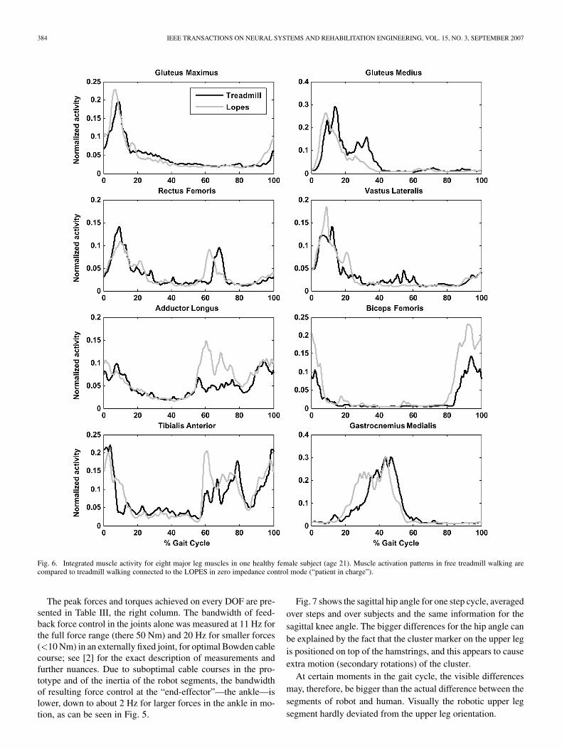
In order to show the effect of these torques on walking, the in-tegrated EMG patterns of eight major leg muscles are comparedfor free treadmill walking and walking when connected to theLOPES controlled in zero impedance mode (Fig. 6). AnalyzingFig. 6, notice that the difference in patterns is small, especiallywhen timing is considered, and that the Biceps Femoris showsan increase in EMG amplitude. This change takes place in thelate swing, and can possibly be attributed to the increased legmass. Also, the Adductor Longus and the Tibialis Anterior showslight but remarkable changes. The change in adductor activitywas accompanied by a smaller step width. The change in Tib-ialis Anterior can also be explained by the extra mass, togetherwith the need to assure sufficient foot clearance during swing.
The Glutues Medius shows a slight decrease in activity duringlate stance. This may be attributed to less active push-off, as theprogression of the subject is assured by the moving treadmilland forces on the pelvis keeping the subject in place.
384 IEEE TRANSACTIONS ON NEURAL SYSTEMS AND REHABILITATION ENGINEERING, VOL. 15, NO. 3, SEPTEMBER 2007
Fig. 6. Integrated muscle activity for eight major leg muscles in one healthy female subject (age 21). Muscle activation patterns in free treadmill walking arecompared to treadmill walking connected to the LOPES in zero impedance control mode (“patient in charge”).
The peak forces and torques achieved on every DOF are pre-sented in Table III, the right column. The bandwidth of feed-back force control in the joints alone was measured at 11 Hz forthe full force range (there 50 Nm) and 20 Hz for smaller forces( 10 Nm) in an externally fixed joint, for optimal Bowden cablecourse; see [2] for the exact description of measurements andfurther nuances. Due to suboptimal cable courses in the pro-totype and of the inertia of the robot segments, the bandwidthof resulting force control at the “end-effector”—the ankle—islower, down to about 2 Hz for larger forces in the ankle in mo-tion, as can be seen in Fig. 5.
Fig. 7 shows the sagittal hip angle for one step cycle, averagedover steps and over subjects and the same information for thesagittal knee angle. The bigger differences for the hip angle canbe explained by the fact that the cluster marker on the upper legis positioned on top of the hamstrings, and this appears to causeextra motion (secondary rotations) of the cluster.
At certain moments in the gait cycle, the visible differencesmay, therefore, be bigger than the actual difference between thesegments of robot and human. Visually the robotic upper legsegment hardly deviated from the upper leg orientation.

VENEMAN et al.: DESIGN AND EVALUATION OF THE LOPES EXOSKELETON ROBOT 385
Fig. 7. Graphs of the sagittal hip and knee angles of both human (position tracking measurement with leg-marker-clusters) and robot (joint angle measurements)for several strides during slow walking (0.75 m/s).
V. DISCUSSION
The prototype of LOPES is fully functional. Until now, about30 healthy persons have “walked in” the device for about anhour in the “patient in charge” mode without any mechanicalproblems. (a movie can be found ). However, for use in clinicalresearch LOPES must be made fully patient safe. This implies,for example, an independent safety circuit that can power thesystem down in case of any danger and a covering of all possibledangerous moving parts.
The slip that appeared during applying peak torques can besolved by not relying on the friction between cable and disc forforce transmission, but by rigidly fixing the cables to this disk.Another design optimization can be made in reducing the weightof the leg parts, as these largely determine the resistive torqueswhile moving the legs. The weight of the legs can be consid-erably reduced by reducing their dimensions and selecting dif-ferent materials, and as such are merely a matter of productengineering.
The evaluations showed a decent agreement to the stated de-mands. Although the resistive torques in the “patient in charge”mode may seem considerable, all people that walked in theLOPES robot reported to experience little to no obstruction tonormal walking. This is explained by the relatively slow move-ments that take place and due to the natural feel of a slight in-crease of mass. This experience is supported by the EMG mea-surements, which show only slight differences between walkingwith and without the LOPES device. Our findings agree with lit-erature on walking with added weight [25].
The differences in the orientation between the human and therobotic limbs appear to be reasonably small, at least for controlpurpose. A substantial part of the error in hip angle appeared tobe caused by secondary rotations of the marker clusters, causedby deformation of the leg due to muscle contractions. A morecritical comparison between orientations is recommended forfuture work in order to judge on the feasibility of the LOPESrobot for inverse-dynamics gait measurements. Current mea-surements indicate that position/angle measurement of the legs
1http://www.bw.ctw.utwente.nl/research/projects/
via the robot device is not sufficiently accurate for inverse dy-namic calculations. However, it appeared accurate enough for asafe implementations of an impedance controller that interfereswith a walking subject [26].
VI. CONCLUSION
We designed and evaluated a gait rehabilitation robot proto-type that functions as a kinaesthetic (mechanically interactive)interface. It is impedance controlled on eight DOFs and ca-pable of a force bandwidth of 4 Hz for large forces up to 12 Hzfor smaller forces. Its DOFs allow free leg motions and a free3-D translation of the pelvis, maintaining the fundamental in-stability of upright standing and walking. The only possibly im-portant motions that are blocked (except for play) are the pelvisrotations.
The robot is an exoskeleton that moves in parallel with thelegs of a person walking on a treadmill, at pelvis height flexiblyconnected to the fixed world. It allows people to walk unhin-dered in its “patient in charge mode. It also allows enforcing agait pattern when configured for its “robot in charge” mode. Theactual use will be in between both modes; in its so called “ther-apist in charge” mode, where selective corrective or supportivetorques can be applied to the leg-joints and the pelvis of patientswho are walking on their own effort.
Evaluation of the design showed that unhindered walking inthe device is very possible, and that any torques/forces needed toimpose a gait pattern can be achieved. Also, limb orientations ofthe robot and the walking subject agree well, sufficient for stableimplementation of training and lower level control. Preliminaryresults of leg muscle EMG measurements show little deviationbetween treadmill walking and walking with the LOPES ex-oskeleton. However, any clinical evaluation with patients hasyet to be carried out.
ACKNOWLEDGMENT
The authors would like to thank G.-J. Nevenzel for his tech-nical contribution to the project.

386 IEEE TRANSACTIONS ON NEURAL SYSTEMS AND REHABILITATION ENGINEERING, VOL. 15, NO. 3, SEPTEMBER 2007
REFERENCES
[1] H. Van der Kooij, J. Veneman, and R. Ekkelenkamp, “Design of a com-pliantly actuated exo-skeleton for an impedance controlled gait trainerrobot,” in Proc. 28th Annu. Int. Conf. IEEE Eng. Med. Biol. Soc., NewYork City, Aug. 2006, pp. 189–193.
[2] J. F. Veneman, R. Ekkelenkamp, R. Kruidhof, F. C. T. van der Helm,and H. van der Kooij, “A Series elastic- and bowden-cable-based ac-tuation system for use as torque actuator in exoskeleton-type robots,”Int. J. Robot. Res., vol. 25, pp. 261–281, Mar. 1, 2006.
[3] P. Lum, D. Reinkensmeyer, R. Mahoney, W. Z. Rymer, and C. Burgar,“Robotic devices for movement therapy after stroke: Current statusand challenges to clinical acceptance,” Top Stroke Rehabil., vol. 8, pp.40–53, 2002.
[4] K. H. Mauritz, “Gait training in hemiparetic stroke patients,” EuraMedicophys., vol. 40, pp. 165–178, Sep. 2004.
[5] B. H. Dobkin, “Strategies for stroke rehabilitation,” Lancet Neurol.,vol. 3, pp. 528–536, Sep. 2004.
[6] S. Hesse, H. Schmidt, C. Werner, and A. Bardeleben, “Upper and lowerextremity robotic devices for rehabilitation and for studying motor con-trol,” Current Opinion Neurol., vol. 16, pp. 705–710, Dec. 2003.
[7] G. Colombo, M. Joerg, R. Schreier, and V. Dietz, “Treadmill training ofparaplegic patients using a robotic orthosis,” J. Rehabil. Res. Develop.,vol. 37, pp. 693–700, 2000.
[8] D. J. Reinkensmeyer, D. Aoyagi, J. L. Emken, J. A. Galvez, W. Ichi-nose, G. Kerdanyan, S. Maneekobkunwong, K. Minakata, J. A. Nessler,R. Weber, R. R. Roy, R. de Leon, J. E. Bobrow, S. J. Harkema, andV. R. Edgerton, “Tools for understanding and optimizing robotic gaittraining,” J. Rehabil. Res. Develop., vol. 43, pp. 657–670, Sep.–Oct.2006.
[9] S. Hesse and D. Uhlenbrock, “A mechanized gait trainer for restorationof gait,” J. Rehabil. Res. Develop., vol. 37, pp. 701–708, 2000.
[10] H. Schmidt, C. Werner, R. Bernhardt, S. Hesse, and J. Kruger, “Gaitrehabilitation machines based on programmable footplates,” J. Neu-roeng. Rehabil., vol. 4, p. 2, 2007.
[11] G. Kwakkel, R. C. Wagenaar, J. W. Twisk, G. J. Lankhorst, and J. C.Koetsier, “Intensity of leg and arm training after primary middle-cere-bral-artery stroke: A randomised trial,” Lancet, vol. 354, pp. 191–196,1999.
[12] M. Lotze, C. Braun, N. Birbaumer, S. Anders, and L. G. Cohen, “Motorlearning elicited by voluntary drive,” Brain, vol. 126, pp. 866–872, Apr.2003.
[13] N. A. Bayona, J. Bitensky, K. Salter, and R. Teasell, “The role of task-specific training in rehabilitation therapies,” Topics Stroke Rehabil.,vol. 12, pp. 58–65, 2005.
[14] L. Nilsson, J. Carlsson, A. Danielsson, A. Fugl-Meyer, K. Hellstrom, L.Kristensen, B. Sjolund, K. S. Sunnerhagen, and G. Grimby, “Walkingtraining of patients with hemiparesis at an early stage after stroke: Acomparison of walking training on a treadmill with body weight sup-port and walking training on the ground,” Clin. Rehabil., vol. 15, pp.515–527, 2001.
[15] N. Hogan, H. I. Krebs, B. Rohrer, J. J. Palazzolo, L. Dipietro, S. E. Fa-soli, J. Stein, R. Hughes, W. R. Frontera, D. Lynch, and B. T. Volpe,“Motions or muscles? Some behavioral factors underlying robotic as-sistance of motor recovery,” J. Rehabil. Res. Develop., vol. 43, pp.605–618, Sep.–Oct. 2006.
[16] R. Riener, L. Lunenburger, and G. Colombo, “Human-centeredrobotics applied to gait training and assessment,” J. Rehabil. Res.Develop., vol. 43, pp. 679–694, Sep.–Oct. 2006.
[17] R. Q. V. D. Linde and P. Lammertse, “HapticMaster—A generic forcecontrolled robot for human interaction,” Industrial Robot, vol. 30, pp.515–524, 2003.
[18] H. van der Kooij, J. Veneman, and R. Ekkelenkamp, “Compliantactuation of exoskeletons,” in Mobile Robotics—Towards New Ap-plications, A. Lazinica, Ed. Mammendorf, Germany: Verlag RoberMayer-Scholz, 2006.
[19] R. Ekkelenkamp, J. Veneman, and H. van der Kooij, “LOPES: Selectivecontrol of gait functions during the gait rehabilitation of CVA patients,”in 9th Int. Conf. Rehabil. Robot., Chicago, IL, 2005, pp. 361–364.
[20] J. F. Israel, D. D. Campbell, J. H. Kahn, and T. G. Hornby, “Metaboliccosts and muscle activity patterns during robotic- and therapist-assistedtreadmill walking in individuals with incomplete spinal cord injury,”Physical Therapy, vol. 86, pp. 1466–1478, Nov. 2006.
[21] D. P. Ferris, J. M. Czerniecki, and B. Hannaford, “An ankle-foot or-thosis powered by artificial pneumatic muscles,” J. Appl. Biomech., vol.21, pp. 189–197, May 2005.
[22] H. I. Krebs and N. Hogan, “Therapeutic robotics: A technology push,”Proc. IEEE, vol. 94, no. 9, pp. 1727–1738, Sep. 2006.
[23] D. A. Winter, Biomechanics and Motor Control of Human Movement,2nd ed. New York: Wiley, 1990.
[24] J. A. Galvez, G. Kerdanyan, S. Maneekobkunwong, R. Weber, M.Scott, S. J. Harkema, and D. J. Reinkensmeyer, “Measuring humantrainers’ skill for the design of better robot control algorithms for gaittraining after spinal cord injury,” in 9th Int. Conf. Rehabil. Robotics,2005, pp. 231–234.
[25] E. H. F. Van Asseldonk, R. Ekkelenkamp, J. F. Veneman, F. C. T. Vander Helm, and H. Van der Kooij, “Selective control of a subtask ofwalking in a robotic gait trainer(LOPES),” presented at the 10th Int.Congress Rehabil. Robotics, Noordwijk aan Zee, 2007.
[26] J. W. Noble and S. D. Prentice, “Adaptation to unilateral change inlower limb mechanical properties during human walking,” Exp. BrainRes., vol. 169, pp. 482–95, Mar. 2006.
Jan F. Veneman, photograph and biography not available at the time ofpublication.
Rik Kruidhof, photograph and biography not available at the time ofpublication.
Edsko E. G. Hekman, photograph and biography not available at the time ofpublication.
Ralf Ekkelenkamp, photograph and biography not available at the time ofpublication.
Edwin H. F. Van Asseldonk, photograph and biography not available at thetime of publication.
Herman van der Kooij, photograph and biography not available at the time ofpublication.