Design and Evaluation of a Multi-Mode Robotic Arm Orthosis ...
12
Çukurova Üniversitesi Mühendislik Mimarlık Fakültesi Dergisi, 33(3), ss. 133-144, Eylül 2018 Çukurova University Journal of the Faculty of Engineering and Architecture, 33(3), pp. 133-144, September 2018 Ç.Ü. Müh. Mim. Fak. Dergisi, 33(3), Eylül 2018 133 Design and Evaluation of a Multi-Mode Robotic Arm Orthosis using Musculoskeletal Simulation Erkan ÖDEMİŞ *1 , Cabbar Veysel BAYSAL 1 1 Çukurova Üniversitesi, Mühendislik Fakültesi, Biyomedikal Mühendisliği Bölümü, Adana Geliş tarihi: 02.05.2018 Kabul tarihi: 15.10.2018 Abstract Robotic upper extremity orthoses have been used in rehabilitation for therapy of neuromuscular disorders and successful implementations are demonstrated by numerous clinical results. Majority of researchers focused on orthotic devices enabling basic therapy mode operations. However, there is still need for new orthotic designs which facilitates therapy modes and assistance for daily life activities in coherence. In this work, design of a multi-mode two DoF robotic arm orthosis is introduced. The designed robotic orthosis is implemented in simulation and tested with a human arm musculoskeletal model, for compliant operation. It uses model based computed torque controller and is tested for multi-mode operation. The performance is evaluated for compliant operation of “Assistive” and “Resistive” rehabilitation modes. Performance tests yielded encouraging results for future developments. Keywords: Robotic arm orthosis, Model-based controller, Musculoskeletal modelling, Simulation Çok-Düzenli Robotik Kol Ortezinin Kas-iskelet Modeli Kullanılarak Tasarımı ve Performans Değerlendirmesi Öz Robotik kol ortezleri, motor-kas becerilerini kaybetmiş hastaların tedavisinde kullanılan ve başarıları sayısız klinik çalışmayla kanıtlanmış cihazlardır. Bu alandaki araştırmaların çoğu temel terapi düzeni operasyonlarını sağlayan ortotik cihazlara odaklanmıştır. Bununla birlikte terapi düzenlerini ve günlük aktiviteler için desteği uyumla gerçekleştirebilecek yeni ortotik cihaz tasarımlarına hala ihtiyaç vardır. Bu çalışmada çok düzenli, iki serbestlik derecesine sahip bir ortez tasarımı yapılmıştır. Tasarlanan ortez uyumlu çalışma becerisi açısından bir kas-iskelet modeli üzerinde benzetim ortamında denenmiştir. Ortez, model tabanlı hesaplamalı tork kontrolcü kullanmaktadır ve çok düzenli çalışma için test edilmiştir. Ortezin performansı “Yardımcı” ve “Dirençli” rehabilitasyon düzenlerinin uyumlu çalışması açısından değerlendirilmiştir. Performans testleri ilerde yapılacak geliştirmeler için cesaret verici sonuçlar vermektedir. Anahtar Kelimeler: Robotik kol ortezi, Model-tabanlı kontrolcü, Kas-iskelet modeli, Benzetim * Corresponding author (Sorumlu yazar): Erkan ÖDEMİŞ, [email protected]
Transcript of Design and Evaluation of a Multi-Mode Robotic Arm Orthosis ...
Çukurova Üniversitesi Mühendislik Mimarlık Fakültesi Dergisi, 33(3), ss. 133-144, Eylül 2018 Çukurova University Journal of the Faculty of Engineering and Architecture, 33(3), pp. 133-144, September 2018
Ç.Ü. Müh. Mim. Fak. Dergisi, 33(3), Eylül 2018 133
Design and Evaluation of a Multi-Mode Robotic Arm Orthosis using
Musculoskeletal Simulation
Erkan ÖDEMİŞ*1, Cabbar Veysel BAYSAL1
1Çukurova Üniversitesi, Mühendislik Fakültesi, Biyomedikal Mühendisliği Bölümü, Adana
Geliş tarihi: 02.05.2018 Kabul tarihi: 15.10.2018
Abstract
Robotic upper extremity orthoses have been used in rehabilitation for therapy of neuromuscular disorders
and successful implementations are demonstrated by numerous clinical results. Majority of researchers
focused on orthotic devices enabling basic therapy mode operations. However, there is still need for new
orthotic designs which facilitates therapy modes and assistance for daily life activities in coherence. In
this work, design of a multi-mode two DoF robotic arm orthosis is introduced. The designed robotic
orthosis is implemented in simulation and tested with a human arm musculoskeletal model, for compliant
operation. It uses model based computed torque controller and is tested for multi-mode operation. The
performance is evaluated for compliant operation of “Assistive” and “Resistive” rehabilitation modes.
Performance tests yielded encouraging results for future developments.
Keywords: Robotic arm orthosis, Model-based controller, Musculoskeletal modelling, Simulation
Çok-Düzenli Robotik Kol Ortezinin Kas-iskelet Modeli Kullanılarak Tasarımı ve
Performans Değerlendirmesi
Öz
Robotik kol ortezleri, motor-kas becerilerini kaybetmiş hastaların tedavisinde kullanılan ve başarıları
sayısız klinik çalışmayla kanıtlanmış cihazlardır. Bu alandaki araştırmaların çoğu temel terapi düzeni
operasyonlarını sağlayan ortotik cihazlara odaklanmıştır. Bununla birlikte terapi düzenlerini ve günlük
aktiviteler için desteği uyumla gerçekleştirebilecek yeni ortotik cihaz tasarımlarına hala ihtiyaç vardır. Bu
çalışmada çok düzenli, iki serbestlik derecesine sahip bir ortez tasarımı yapılmıştır. Tasarlanan ortez
uyumlu çalışma becerisi açısından bir kas-iskelet modeli üzerinde benzetim ortamında denenmiştir. Ortez,
model tabanlı hesaplamalı tork kontrolcü kullanmaktadır ve çok düzenli çalışma için test edilmiştir.
Ortezin performansı “Yardımcı” ve “Dirençli” rehabilitasyon düzenlerinin uyumlu çalışması açısından
değerlendirilmiştir. Performans testleri ilerde yapılacak geliştirmeler için cesaret verici sonuçlar
vermektedir.
Anahtar Kelimeler: Robotik kol ortezi, Model-tabanlı kontrolcü, Kas-iskelet modeli, Benzetim
*Corresponding author (Sorumlu yazar): Erkan ÖDEMİŞ, [email protected]

Design and Evaluation of a Multi-Mode Robotic Arm Orthosis Using Musculoskeletal Simulation
134 Ç.Ü. Müh. Mim. Fak. Dergisi, 33(3), Eylül 2018
1. INTRODUCTION
Many people lose their neuromuscular abilities due
to accidents and illnesses which affect their daily
life negatively. Physiotherapy and rehabilitation
are widely used methods for treating patients with
neuromuscular disabilities. In traditional manner,
exercises are performed with therapists but there
are some disadvantages such as not enough time
being spent with each patient or performance
reduction in exercises due overloading. On the
other hand, performing exercises with robotic
devices has appeared as a new approach to
overcome disadvantages of traditional treatment
methods mentioned above [1,2].
Robotic rehabilitation devices have many
advantages such as eliminating constraints on
therapy time, giving the opportunity of local
treatment under suitable conditions, facilitating
evaluation and understanding the changes in
patient’s condition. Robotic rehabilitation devices
can be classified according to their applied
segment such as lower limb, upper limb or whole
body [3]. Robotic orthoses are assistant devices
fixed to the body to increase the performance of
the limbs with partial functional losses. Robotic
arm orthosis for rehabilitation belong to the upper
extremity class of the rehabilitation devices [4].
Patients can perform rehabilitation exercises with
these devices in different modes such as assistive,
resistive, and repetitive [4,5]. The devices with
active assistance help patients with daily activities
like reaching and grasping [5]. In assistive
exercises, the device helps patients complete the
intended movements by applying external force
[6]. Resistive mode in contrast to assistive mode
aims to make patient spend more effort by adding
some disruptive effects to the patient's movement [6].
The robotic arm orthoses could also be categorized
according to mechanical designs and control
methods [3,5,7]. The mechanical designs are
classified with respect to number of joints,
actuators used for motion and power transmission
methods [3,4]. Different types of actuators are
used such as pneumatic actuators, hydraulic
actuators and motors [7]. Power transmission can
be either gear driven or cable driven systems [3,4].
Controllers used in robotic orthotic devices could
be grouped as model based, hierarchy based and
physical parameters based control systems [8].
Model based control strategies can be grouped into
dynamic model based controllers and muscle
model based controllers [7]. The dynamic model
is derived through modeling the human body as
rigid links joined together by joints [8]. This model
tries to estimate the torque produced by inertia,
gravitational, coriolis and centrifugal effects [9].
Unlike the dynamic model, muscle model
estimates the muscle moment as a function of
muscle activation level and joint kinematics [8]. In
muscle model, the input is EMG signal and the
output is the force estimation [10].
Hierarchy based control can be studied at three
levels: Task level, high level and low level. [8].
Task level control involves the highest level
controller which produces command signals
according to tasks designed in controller structure.
The next controller level is the high level
controller. It is responsible for the control of the
force and position of the human-orthosis
interaction according to the command signals from
the task level controller. The high level controller
is generally impedance and admittance controllers
[11–14]. Lowest in the hierarchy is the low level
controller. It is generally force and position
controllers [10,13]. Physical parameter based
controllers can be classified under three groups
such as position controller, torque/force controller
and force interaction controller [8].
In this work, we propose, a multi-mode robotic
arm orthosis which enables assistive and resistive
modes in coherence, as well as providing an
opportunity for easy transition between these
modes. In our orthosis implementation,
rehabilitation exercises and assistance for daily
activities could be done with same device, in
contrast to many other single mode orthotic
devices [6,9,10]. The designed robotic arm
orthosis uses model-based computed torque
controller due to its simplicity and stability. The
designed orthosis was tested with a human arm
musculoskeletal model in order to evaluate the
multi-mode performance in simulation. The design

Erkan ÖDEMİŞ, Cabbar Veysel BAYSAL
Ç.Ü. Müh. Mim. Fak. Dergisi, 33(3), Eylül 2018 135
approach using musculoskeletal simulation could
be utilized as an evaluation criterion for future
stages of hardware implementation. In the
following sections, design and implementation
stages with simulation results are presented.
2. MATERIALS AND METHODS
In this work, design of a multi-mode robotic arm
orthosis, which enables assistive and resistive
rehabilitation modes, was proposed. Rehabilitation
modes and mode transitions have been tested with
the musculoskeletal model that has been designed
in the MSMS (Musculoskeletal Modelling
Software) and Matlab/Simulink [15]. The software
packages were used for simulating the design of
the musculoskeletal model in combination. The
orthosis mechanical design has been exported to
Matlab/Simmechanics environment. Model based
computed torque controller was used for the
control of orthotic device meanwhile the activation
signals for the musculoskeletal model were
controlled by a separate proportional–integral–
derivative (PID) controller. The performance
evaluation of the orthosis is done with respect to
simulation results. The simulation yielded
encouraging results to demonstrate multi-mode
operation.
2.1. Orthosis Mechanical Design
The orthosis design consists of two parts:
controller design and mechanical design.
Mechanical design of the orthosis was performed
using Solidworks. A simple design with two
degrees of freedom (DoF) (shoulder
flexion/extension and elbow flexion/extension
joints) was used in the orthosis design to focus
rehabilitation mode implementations, avoiding
problems arising from complexity of mechanical
design. The CAD drawing of the designed orthosis
in Solidworks is given in Figure 1.
Physical parameters of the orthosis links, which
were obtained from Solidworks, are given in Table
1; where Ii represents moment of inertia, mi is the
mass, and lci is the distance from the i-th joint to
the i-th mass center position and li is the length of
the i-th link.
Figure 1. CAD drawing of the designed orthosis
Table 1. Physical parameters of the orthosis links
mi
[Kg] Ii [Kg m2] lci [m] li [m]
i =1 1.72 0.05 0.13 0.28
i = 2 1.74 0.04 0.12 0.27
Range of motions (ROM) of the orthosis joints has
been restricted according to the values in the
literature [16]. These ROM values are given in the
Table 2.
Table 2. ROMs of the orthosis joints
Joint ROM [Degree]
Shoulder Flexion 176
Shoulder Extension 66
Elbow Flexion 142
Elbow Extension 4
The orthosis dynamics were derived by using
Lagrangian approach [17]. Dynamic model of the
orthosis is in the standard form
M(q)q+V(q,q)q+G(q)=τ+ τh (1)
with M(q) the inertia matrix, V(q,q) the
Coriolis/Centripetal matrix, G(q) the gravity
vector, q the vector of joint positions, 𝜏 the joint
actuator torques of the orthosis and 𝜏ℎ the arm

Design and Evaluation of a Multi-Mode Robotic Arm Orthosis Using Musculoskeletal Simulation
136 Ç.Ü. Müh. Mim. Fak. Dergisi, 33(3), Eylül 2018
model’s torque input . Details of M(q), V(q,q) and
G(q) are given in Appendix A.
2.2. Human Arm Musculoskeletal Model
Musculoskeletal modelling of human arm was
achieved with Musculoskeletal Modelling
Software (MSMS). There are many software tools
for musculoskeletal modelling such as SIMM
(Software for Interactive Musculoskeletal
Modelling) [18], OpenSim [19] and AnyBody
(Anybody Technology, Aalborg, Denmark) [20].
However, the MSMS program was chosen in this
work because it has General Public License (GPL)
and permits conversion of musculoskeletal and
orthosis models to Matlab/Simulink in order to
perform simulation with controllers in place.
The muscle model used in MSMS is a modified
Hill muscle model (Virtual muscle model) [15,21].
Hill muscle model estimates the muscle force as a
function of muscle activation level, muscle
parameters and joint kinematics [22]. It consists of
active Contractile Element (CE), Parallel Element
(PE) and Series Passive Element (SPE) [22–24] as
shown in Figure 2. The CE refers to the
contraction process that generates the active force.
The SPE and PE components represent passive
soft connective tissue including the tendon and the
nonactive muscle fibers. Details of Hill muscle
model are given in Appendix B.
Figure 2. Schematic of the hill muscle model
MSMS version 2.2 was used in this work. This
version contains some examples of human
musculoskeletal models including the human
upper limb. The muscles of this upper limb model
have been modified, according to active joints and
the muscle parameters in the literature and used in
this paper. In the designed musculoskeletal model,
Deltoid Anterior and Pectoralis Major Clavicular
muscles were used for shoulder flexion movement;
Deltoid Posterior muscle was used for shoulder
extension movement; Biceps Long Head and
Brachialis muscles were used for elbow flexion
movement; and Triceps Long Head and Triceps
Lateral Head muscles were used for elbow
extension movement. The muscle parameters
which were obtained from studies in the literature
[25–28] are given in Table 3.
Table 3. Muscle parameters used in MSMS
Muscle
Opt.
Fascicle
Length
[cm]
Opt.
Tendon
Length
[cm]
Max MT
Length
[cm]
Mass
[g]
B. Long 15.6 19.11 37 80
Brachi. 8.6 5.67 15 338
Del. Ant. 10.1 2.73 16 410
Del. Post. 13.7 4 19 92
Pec. Maj. 14.4 0.315 19 214
T. Long 13.4 15.015 32 345
T. Lat. 11.4 10.29 24 273
The final state of the design obtained by
transferring the CAD drawings of the orthosis to
the MSMS environment is shown in Figure 3.
Figure 3. Orthosis and musculoskeletal model in
MSMS platform

Erkan ÖDEMİŞ, Cabbar Veysel BAYSAL
Ç.Ü. Müh. Mim. Fak. Dergisi, 33(3), Eylül 2018 137
2.3. Orthosis and Musculoskeletal Model
Implementation in Simulation
Simulation tool of MSMS, which converts
musculoskeletal models to Simulink block
diagrams, was used to transfer the designed
orthosis and musculoskeletal model to
Matlab/Simulink. The block diagram of the
transferred model is given in Figure 4.
Figure 4. Block diagram of the transferred model
from MSMS to Matlab/Simulink
The Plant Block shown in Figure 4 contains the
mechanical models of the human skeleton and the
orthosis. In the Driver Block, there are S Function
blocks that contain the parameters of the muscles
in the model and muscle path information.
The Virtual Muscle Model (Musculoskeletal
Model) uses muscle activation as input. By using
muscle activation information and muscle
parameters, the forces generated by muscles are
calculated. Muscle activation information is
usually obtained by using EMG signals [29].
In this work, muscle activations were obtained by
using PID controllers based on desired trajectories.
Four PID controllers, one for the muscles
responsible for the shoulder flexion motion
(Deltoid Anterior and Pectoralis Major
Clavicular), one for the muscle responsible for the
shoulder extension motion (Deltoid Posterior), one
for the muscles responsible for the elbow flexion
motion (Biceps Long Head and Brachialis) and
one for the muscles responsible for the elbow
extension motion (Triceps Long Head and Triceps
Lateral Head), were used. Differences between the
joint positions of the musculoskeletal model and
the trajectories of desired exercise tasks were used
as PID controller inputs. Since the muscle
activation could range from 0 to 1, the outputs of
the PID controllers were limited between these
values by adding Simulink saturation blocks
[23,29]. The schematic of the PID controller used
for muscle activation is given in Figure 5.
Figure 5. Schematic of the muscle activation PID
controller
Orthosis is connected to human arm
musculoskeletal model with body spring damper
block in Simulink. This block is used to connect
human arm model and orthosis in a flexible
manner to simulate a real connection. It is also
aimed to observe the interaction between arm
model and orthosis during mode transitions.
Human arm musculoskeletal model and orthosis
have the same two active DoFs (shoulder and
elbow flexion/extension joints) and they move on
sagittal plane. Also, the orthosis link lengths were
selected according to the musculoskeletal model
links to avoid joint misalignments. Thus, it was
ensured that the joint positions of the orthosis and
musculoskeletal model were the same by using the
body spring damper block. Body spring damper
block's parameters were determined based on
simulation studies.
2.4. Multi-Mode Model Based Controller
The main control approach for the orthosis was
based on the computed torque control method.
Computed torque controller is a model-based
control method which uses the dynamic model of
the system to compute the control torque signals
that are input of the system [17]. This controller
generally performs well when the robot arm
dynamic parameters are known accurately and it

Design and Evaluation of a Multi-Mode Robotic Arm Orthosis Using Musculoskeletal Simulation
138 Ç.Ü. Müh. Mim. Fak. Dergisi, 33(3), Eylül 2018
can also ensure globally asymptotic stability
[30,31].
The designed controller consisted of two loops
where inner loop was orthosis dynamics and outer
loop was PID controller [32]. The PID computed
torque controller method was chosen to avoid the
complexity of intelligent control methods and to
demonstrate that assistive and resistive
rehabilitation modes could be realized with an
easier-to-implement controller.
In the controller structure, u was the outer loop
controlled variable, 𝜏 was joint actuator torques,
𝑞 and �� were joint position and velocity, qd, ��𝑑
and ��𝑑 were desired joint position, velocity, and
acceleration respectively. PID controller output
signal was
u(t)=-(Kpe+Kve+Kiε(t)) (2)
with e tracking error; e = (qd - q), �� = ��𝑑 − �� and
𝜀(𝑡) the integral of the tracking error e(t). Kp, Kv
and Ki are proportional, derivative and integral
gains of the PID controller respectively. Those
gain parameters were tuned by Ziegler Nichols
method [33]. Detailed PID computed torque
controller block diagram is shown in Figure 6. For
the Orthosis control, the following equation was
used.
Figure 6. PID Computed Torque Controller block
diagram
¨ ˙ ˙ ˙
,
p v i hdM q q K e K e K ε t V q q q G q τ τ (3)
2.5. Assistive/Resistive Rehabilitation Modes
and Mode Transitions
Controller assistive/resistive rehabilitation modes
and transition between these modes was done by a
Graphical User Interface (GUI) designed in
Matlab. The designed GUI is shown in Figure 7.
Figure 7. Matlab Graphical User Interface (GUI) a) Sections of assistive/resistive mode control panels,
b) Start, stop and plot push buttons
Resistive and assistive modes of the orthosis were
realized by gain adjustment blocks connected to
torque outputs of the PID computed torque
controller (𝜏 in Equation 3), which was applied to
orthosis joints as shown in Figure 8. By changing
the gain values, in the assistive mode, joint
Erkan ÖDEMİŞ, Cabbar Veysel BAYSAL
Ç.Ü. Müh. Mim. Fak. Dergisi, 33(3), Eylül 2018 139
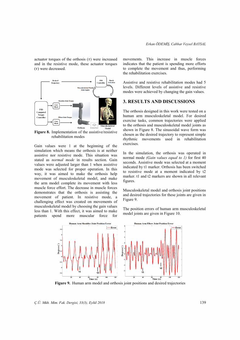
actuator torques of the orthosis (𝜏) were increased
and in the resistive mode, these actuator torques
(𝜏) were decreased.
Figure 8. Implementation of the assistive/resistive
rehabilitation modes
Gain values were 1 at the beginning of the
simulation which means the orthosis is at neither
assistive nor resistive mode. This situation was
stated as normal mode in results section. Gain
values were adjusted larger than 1 when assistive
mode was selected for proper operation. In this
way, it was aimed to make the orthosis help
movement of musculoskeletal model, and make
the arm model complete its movement with less
muscle force effort. The decrease in muscle forces
demonstrates that the orthosis is assisting the
movement of patient. In resistive mode, a
challenging effect was created on movements of
musculoskeletal model by choosing the gain values
less than 1. With this effect, it was aimed to make
patients spend more muscular force for
movements. This increase in muscle forces
indicates that the patient is spending more efforts
to complete the movement and thus, performing
the rehabilitation exercises.
Assistive and resistive rehabilitation modes had 5
levels. Different levels of assistive and resistive
modes were achieved by changing the gain values.
3. RESULTS AND DISCUSSIONS
The orthosis designed in this work were tested on a
human arm musculoskeletal model. For desired
exercise tasks, common trajectories were applied
to the orthosis and musculoskeletal model joints as
shown in Figure 8. The sinusoidal wave form was
chosen as the desired trajectory to represent simple
rhythmic movements used in rehabilitation
exercises.
In the simulation, the orthosis was operated in
normal mode (Gain values equal to 1) for first 40
seconds. Assistive mode was selected at a moment
indicated by t1 marker. Orthosis has been switched
to resistive mode at a moment indicated by t2
marker. t1 and t2 markers are shown in all relevant
figures.
Musculoskeletal model and orthosis joint positions
and desired trajectories for these joints are given in
Figure 9.
The position errors of human arm musculoskeletal
model joints are given in Figure 10.
Figure 9. Human arm model and orthosis joint positions and desired trajectories
Design and Evaluation of a Multi-Mode Robotic Arm Orthosis Using Musculoskeletal Simulation
140 Ç.Ü. Müh. Mim. Fak. Dergisi, 33(3), Eylül 2018
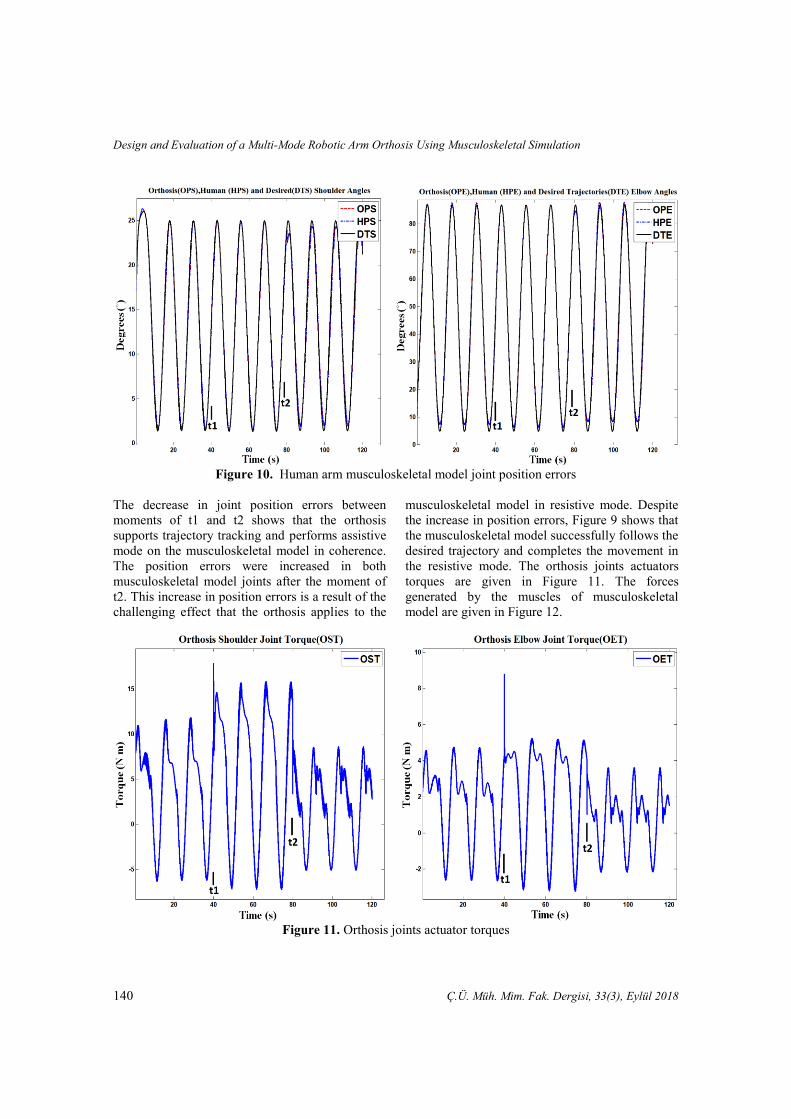
Figure 10. Human arm musculoskeletal model joint position errors
The decrease in joint position errors between
moments of t1 and t2 shows that the orthosis
supports trajectory tracking and performs assistive
mode on the musculoskeletal model in coherence.
The position errors were increased in both
musculoskeletal model joints after the moment of
t2. This increase in position errors is a result of the
challenging effect that the orthosis applies to the
musculoskeletal model in resistive mode. Despite
the increase in position errors, Figure 9 shows that
the musculoskeletal model successfully follows the
desired trajectory and completes the movement in
the resistive mode. The orthosis joints actuators
torques are given in Figure 11. The forces
generated by the muscles of musculoskeletal
model are given in Figure 12.
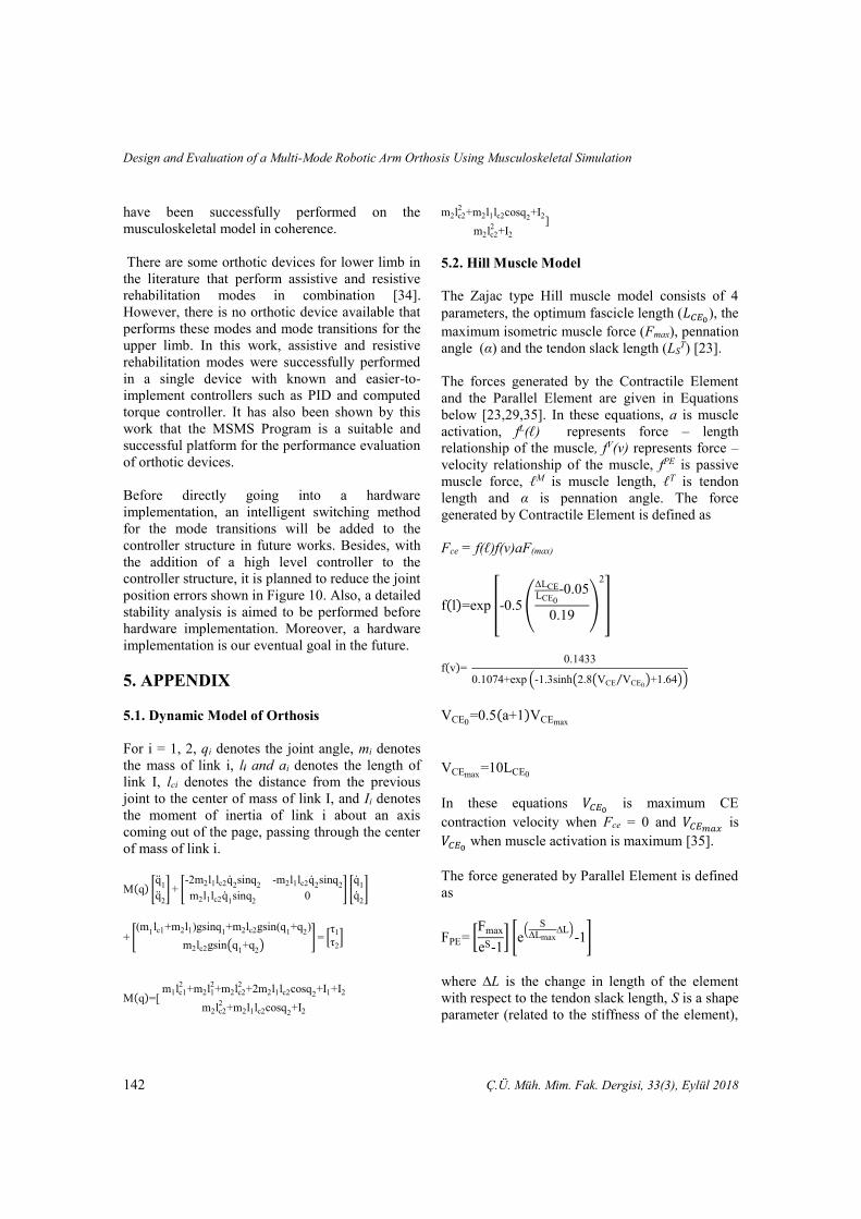
Figure 11. Orthosis joints actuator torques

Erkan ÖDEMİŞ, Cabbar Veysel BAYSAL
Ç.Ü. Müh. Mim. Fak. Dergisi, 33(3), Eylül 2018 141
Figure 12. Muscle forces of the musculoskeletal model
Figure 11 shows, joint torques of orthosis
increased for assisting to movement of the
musculoskeletal model in the assistive mode, and
in the resistive mode, joint torques decreased,
compared to the normal mode, for making the arm
model movement more difficult.
Figure 12 shows that Biceps Long force has
decreased about 10 percent, Brachialis, Triceps
Long, Triceps Lateral and Deltoid Posterior forces
have decreased about 30 percent and Deltoid
Anterior and Pectoralis Major forces have
decreased about 50 percent after moment of t1
when the orthosis has gone into assistive mode.
This decrease in muscle forces is a result of
supporting the movement of the musculoskeletal
model in the assistive mode by the orthosis. With
this assistance, the musculoskeletal model could
follow the desired trajectory with less muscle
effort.
In the same figure, it is seen that after the moment
of t2, Biceps Long force has increased about 15
percent, Brachialis, Triceps Lateral, Deltoid
Anterior and Pectoralis Major forces have
increased about 30 percent and Triceps Long and
Pectoralis Major forces have increased about 50
percent when compared with the beginning. The
increase in muscle forces indicates that the orthosis
makes the movement of the musculoskeletal model
more challenging and muscle forces increase to
overcome this challenging effect in the resistive
mode.
Simulation results demonstrate that the designed
orthosis has applied assistive and resistive
rehabilitation modes and mode transitions on the
human arm musculoskeletal model successfully.
4. CONCLUSIONS
In this work, a multi-mode, 2 DoF orthosis which
enables assistive and resistive rehabilitation modes
was designed. The designed orthosis has been
tested in simulation on a musculoskeletal model
created in the MSMS and Matlab/Simulink. In the
musculoskeletal model, PID controllers were used
to obtain muscle activation signals. PID computed
torque controller was used in the orthosis control.
The results obtained from the simulations show
that the assistive and resistive rehabilitation modes
of the designed orthosis and the mode transitions
Design and Evaluation of a Multi-Mode Robotic Arm Orthosis Using Musculoskeletal Simulation
142 Ç.Ü. Müh. Mim. Fak. Dergisi, 33(3), Eylül 2018
have been successfully performed on the
musculoskeletal model in coherence.
There are some orthotic devices for lower limb in
the literature that perform assistive and resistive
rehabilitation modes in combination [34].
However, there is no orthotic device available that
performs these modes and mode transitions for the
upper limb. In this work, assistive and resistive
rehabilitation modes were successfully performed
in a single device with known and easier-to-
implement controllers such as PID and computed
torque controller. It has also been shown by this
work that the MSMS Program is a suitable and
successful platform for the performance evaluation
of orthotic devices.
Before directly going into a hardware
implementation, an intelligent switching method
for the mode transitions will be added to the
controller structure in future works. Besides, with
the addition of a high level controller to the
controller structure, it is planned to reduce the joint
position errors shown in Figure 10. Also, a detailed
stability analysis is aimed to be performed before
hardware implementation. Moreover, a hardware
implementation is our eventual goal in the future.
5. APPENDIX
5.1. Dynamic Model of Orthosis
For i = 1, 2, qi denotes the joint angle, mi denotes
the mass of link i, li and ai denotes the length of
link I, lci denotes the distance from the previous
joint to the center of mass of link I, and Ii denotes
the moment of inertia of link i about an axis
coming out of the page, passing through the center
of mass of link i.
M(q) [q
1
q2
] + [-2m2l1lc2q
2sinq
2-m2l1lc2q
2sinq
2
m2l1lc2q1sinq
20
] [q
1
q2
]
+ [(m
1lc1+m2l1)gsinq
1+m2lc2gsin(q
1+q
2)
m2lc2gsin(q1+q
2)
] = [τ1
τ2]
M(q)=[ m1lc1
2+m2l1
2+m2lc2
2+2m2l1lc2cosq
2+I1+I2
m2lc22
+m2l1lc2cosq2+I2
m2lc22
+m2l1lc2cosq2+I2
m2lc22
+I2
]
5.2. Hill Muscle Model
The Zajac type Hill muscle model consists of 4
parameters, the optimum fascicle length (𝐿𝐶𝐸0), the
maximum isometric muscle force (Fmax), pennation
angle (α) and the tendon slack length (LST) [23].
The forces generated by the Contractile Element
and the Parallel Element are given in Equations
below [23,29,35]. In these equations, a is muscle
activation, fL(ℓ) represents force – length
relationship of the muscle, fV(v) represents force –
velocity relationship of the muscle, fPE is passive
muscle force, ℓM is muscle length, ℓT is tendon
length and α is pennation angle. The force
generated by Contractile Element is defined as
Fce = f(ℓ)f(v)aF(max)
f(l)=exp [-0.5 (
ΔLCELCE0
-0.05
0.19)
2
]
f(v)= 0.1433
0.1074+exp (-1.3sinh(2.8(VCE VCE0⁄ )+1.64))
VCE0=0.5(a+1)VCEmax
VCEmax=10LCE0
In these equations 𝑉𝐶𝐸0 is maximum CE
contraction velocity when Fce = 0 and 𝑉𝐶𝐸𝑚𝑎𝑥 is
𝑉𝐶𝐸0 when muscle activation is maximum [35].
The force generated by Parallel Element is defined
as
FPE= [Fmax
eS-1] [e
(S
∆Lmax∆L)
-1]
where ∆L is the change in length of the element
with respect to the tendon slack length, S is a shape
parameter (related to the stiffness of the element),

Erkan ÖDEMİŞ, Cabbar Veysel BAYSAL
Ç.Ü. Müh. Mim. Fak. Dergisi, 33(3), Eylül 2018 143
Fmax is the maximum force exerted by the element
for the maximum change in length ∆Lmax.
Finally the total force developed by the muscle is
equal to
FMT=FCE+FPE
6. ACKNOWLEDGEMENT
This work is supported by Scientific Research
Project Units of Çukurova University, in project
FYL-2014-2541.
7. REFERENCES
1. Volpe, B.T., Krebs, H.I., Hogan, N., 2001. Is
Robot-aided Sensorimotor Training in Stroke
Rehabilitation a Realistic Option? Curr. Opin.
Neurol. 14, 745–752.
2. Lum, P.S., Burgar, C.G., Shor, P.C.,
Majmundar, M., Van der Loos, M., 2002.
Robot-assisted Movement Training Compared
with Conventional Therapy Techniques for the
Rehabilitation of Upper-limb Motor Function
After Stroke. Arch. Phys. Med. Rehabil. 83,
952–959.
3. Gopura, R.A.R.C., Kiguchi, K., 2009.
Mechanical Designs of Active Upper-limb
Exoskeleton Robots State-of-the-art and
Design Difficulties. 2009 IEEE Int. Conf.
Rehabil. Robot. ICORR 2009 178–187
doi:10.1109/ICORR.2009.5209630.
4. Gopura, R.A.R.C., Bandara, D.S.V., Kiguchi,
K., Mann, G.K.I. 2016. Developments in
Hardware Systems of Active Upper-limb
Exoskeleton Robots: A review. Rob. Auton.
Syst. 75, 203–220
5. Marchal-Crespo, L., Reinkensmeyer, D.J.,
2009. Review of Control Strategies for Robotic
Movement Training After Neurologic Injury. J.
Neuroeng. Rehabil. 6, 20.
6. Wolbrecht, E.T., Chan, V., Reinkensmeyer, D.
J., Bobrow, J.E. 2008. Optimizing Compliant,
Model-based Robotic Assistance to Promote
Neurorehabilitation. IEEE Trans. Neural Syst.
Rehabil. Eng. 16, 286–297.
7. Lo, H.S., Xie, S.Q., 2012. Exoskeleton Robots
for Upper-limb Rehabilitation: State of the Art
and Future Prospects. Med. Eng. Phys. 34,
261–268.
8. Anam, K., Al-Jumaily, A.A., 2012. Active
Exoskeleton Control Systems: State of the Art.
Procedia Eng. 41, 988–994.
9. Lee, H.D., Lee, B.K., Kim, W.S., Han, J.S.,
Shin, K.S., Han, C.S., 2014. Human-robot
Cooperation Control Based on a Dynamic
Model of an Upper Limb Exoskeleton for
Human Power Amplification. Mechatronics 24,
168–176.
10. Rosen, J., Brand, M., Fuchs, M.B., Arcan, M.,
2001. A Myosignal-based Powered
Exoskeleton System. IEEE Trans. Syst. Man,
Cybern. Part ASystems Humans. 31, 210–222.
11. Sugar, T.G., He, J., Koeneman, E.J.,
Koeneman, J.B., Herman, R., Huang, H.,
Schultz, R.S., Herring, D.E., Wanberg, J.,
Balasubramanian, S., Swenson, P., Ward, J.A.,
2007. Design and Control of RUPERT: A
Device for Robotic Upper Extremity Repetitive
Therapy. IEEE Trans. Neural Syst. Rehabil.
Eng. 15, 336–346.
12. Gopura, R.A.R.C., Kiguchi, K., Yi, Y., 2009.
SUEFUL-7: A 7DOF Upper-limb Exoskeleton
Robot with Muscle-model-oriented EMG-
Based Control. 2009 IEEE/RSJ Int. Conf.
Intell. Robot. Syst. IROS 2009 1126–1131,
doi:10.1109/IROS.2009.5353935
13. Crema, A., Mancuso, M., Frisoli, A., Selsedo
F., Raschella, F., Micea, S., 2015. A Hybrid
NMES-exoskeleton for Real Objects
Interaction. Int. IEEE/EMBS Conf. Neural
Eng. NER 2015–July, 663–666.
14. Carignan, C., Tang, J., Roderick, S., 2009.
Development of an Exoskeleton Haptic
Interface for Virtual Task Training. 2009
IEEE/RSJ Int. Conf. Intell. Robot. Syst. IROS
2009 3697–3702, doi:10.1109/IROS.2009.
5354834
15. Davoodi, R., Loeb, G. E., 2011. MSMS
Software for VR Simulations of Neural
Prostheses and Patient Training and
Rehabilitation. Stud. Health Technol. Inform.
163, 156–162.
16. Moromizato, K., Kimura, R., Fukase, H.,
Yamaguchi, K., Ishida, H., 2016. Whole-body
Patterns of the Range of Joint Motion in Young
https://www.ncbi.nlm.nih.gov/pubmed/?term=Schultz%20RS%5BAuthor%5D&cauthor=true&cauthor_uid=17894266

Design and Evaluation of a Multi-Mode Robotic Arm Orthosis Using Musculoskeletal Simulation
144 Ç.Ü. Müh. Mim. Fak. Dergisi, 33(3), Eylül 2018
Adults: Masculine Type and Feminine Type. J.
Physiol. Anthropol. 35, 23.
17. Lewis F.L., Munro N., 2004. Robot
Manipulator Control Theory and Practice.
Marcel Dekker, Inc.
18. Delp, S. L., Loan, J. P., Hoy, M. G., Zajac, F.
E., Topp, E.L., Rosen, J.M., 1990. An
Interactive Graphics-based Model of the Lower
Extremity to Study Orthopedic Surgical
Procedures. IEEE Trans. Biomed. Eng. 37,
757–767.
19. Delp, S.L., Anderson, F.C., Arnold, A.S.,
Loan, P., Habib, A., John, C.T., Guendelman,
E., Thelen, D.G., 2007. OpenSim: Open Source
to Create and Analyze Dynamic Simulations of
Movement. IEEE Trans. Biomed. Eng. 54,
1940–1950.
20. Damsgaard, M., Rasmussen, J., Christensen,
S.T., Surma, E., de Zee, M., 2006. Analysis of
Musculoskeletal Systems in the AnyBody
Modeling System. Simul. Model. Pract. Theory
14, 1100–1111.
21. Cheng, E.J., Brown, I.E., Loeb, G.E., 2001.
Virtual Muscle: A Computational Approach to
Understanding the Effects of Muscle Properties
on Motor Control. J. Neurosci. Methods 106,
111–112.
22. Rosen, J., Fuchs, M. B., Arcan, M., 1999.
Performances of Hill-Type and Neural
Network Muscle Models-Toward a Myosignal-
Based Exoskeleton. Comput. Biomed. Res. 32,
415–439.
23. Zajac, F.E., 1989. Muscle and Tendon:
Properties, Models, Scaling, and Application to
Biomechanics and Motor Control. Crit. Rev.
Biomed. Eng. 17, 359–411.
24. Winters, J. M., 1995. An Improved Muscle-
Reflex Actuator for use in Large-scale
Neuromusculoskeletal Models. Ann. Biomed.
Eng. 23, 359–374.
25. Garner, B.A., Pandy, M.G., 2001.
Musculoskeletal Model of the Upper Limb
Based on the Visible Human Male Dataset.
Comput. Methods Biomech. Biomed. Engin. 4,
93–126.
26. Langenderfer, J., Jerabek, S.A., Thangamani,
V.B., Kuhn, J.E., Hughes, R.E., 2004.
Musculoskeletal Parameters of Muscles
Crossing the Shoulder and Elbow and the
Effect of Sarcomere Length Sample Size on
Estimation of Optimal Muscle Length. Clin.
Biomech. 19, 664–670.
27. Holzbaur, K.R.S., Murray, W.M., Delp, S.L.,
2005. A Model of the Upper Extremity for
Simulating Musculoskeletal Surgery and
Analyzing Neuromuscular Control. Ann.
Biomed. Eng. 33, 829–840.
28. Saul, K.R., Hu X., Goehler C.M., Vidt M.E.,
Daly M., Velisar A., Murray W.M., 2014.
Benchmarking of Dynamic Simulation
Predictions in Two Software Platforms using
an Upper Limb Musculoskeletal Model.
Comput. Methods Biomech. Biomed. Engin.
18, 1–14.
29. Buchanan, T.S., Lloyd, D.G., Manal, K.,
Besier, T.F., 2004. Neuromusculoskeletal
Modeling: Estimation of Muscle Forces and
Joint Moments and Movements from
Measurements of Neural Command. J. Appl.
Biomech. 20, 367–95.
30. Song, Z., Yi, J., Zhao, D., Li, X., 2005. A
Computed Torque Controller for Uncertain
Robotic Manipulator Systems: Fuzzy
Approach. Fuzzy Sets Syst. 154, 208–226.
31. Han, S., Wang, H., Tian, Y., 2017. Integral
Backstepping Based Computed Torque Control
for a 6 DOF Arm Robot. Proc. 29th Chinese
Control Decis. Conf. CCDC 2017 4055–4060.
doi:10.1109/CCDC.2017.7979210
32. Craig J.J., 2005. Introduction to Robotics.
Pearson Education Inc., doi:10.1111/j.1464-
410X.2011.10513.x
33. Ogata K., 2009. Modern Control Engineering.
Pearson Prentice Hall.
34. Chandrapal, M., Chen, X., 2009. Intelligent
Active Assistive and Resistive Orthotic Device
for Knee Rehabilitation. 2009 IEEE Int. Conf.
Control Autom. ICCA 2009 1880–1885
doi:10.1109/ICCA.2009.5410528
35. Cavallaro, E., Rosen, J., Perry, J.C., Burns, S.,
Hannaford, B., 2005. Hill-based Model as a
Myoprocessor for a Neural Controlled Powered
Exoskeleton Arm-Parameters Optimization.
Proc. - IEEE Int. Conf. Robot. Autom. 2005,
4514–4519.