Design and Development of Unmanned Aerial Vehicle (Drone) for ...
63
Design and Development of Unmanned Aerial Vehicle (Drone) for Civil Applications Thesis Project A Thesis submitted to the Dept. of Electrical & Electronic Engineering, BRAC University in partial fulfillment of the requirements for the Bachelor of Science degree in Electrical & Electronic Engineering Project Supervisor Dr. Pran Kanai Saha Project Group A.M. Reasad Azim Bappy - 10110017 MD. Asfak-Ur-Rafi -10321005 MD. Saddamul Islam –11321030 Ali Sajjad - 10321007 Khan Nafis Imran – 10321011
-
Upload
truongdiep -
Category
Documents
-
view
220 -
download
2
Transcript of Design and Development of Unmanned Aerial Vehicle (Drone) for ...

Design and Development of Unmanned Aerial Vehicle
(Drone) for Civil Applications
Thesis Project
A Thesis submitted to the Dept. of Electrical & Electronic Engineering, BRAC
University in partial fulfillment of the requirements for the Bachelor of Science
degree in Electrical & Electronic Engineering
Project Supervisor
Dr. Pran Kanai Saha
Project Group
A.M. Reasad Azim Bappy - 10110017
MD. Asfak-Ur-Rafi -10321005
MD. Saddamul Islam –11321030
Ali Sajjad - 10321007
Khan Nafis Imran – 10321011

i
DECLARATION
We hereby declare that the thesis titled “Design and Development of Unmanned Aerial Vehicle
(Drone) for Civil Applications” is submitted to the Department of Electrical and Electronics
Engineering of BRAC University in partial fulfillment of the Bachelor of Science in Electrical and
Electronics Engineering. This is work was not submitted elsewhere for the award of any other
degree or any other publication.
________________________ ________________________
A.M. Reasad Azim Bappy MD. Asfak-Ur-Rafi-Anonno
Student ID : 10110017 Student ID : 10321005
________________________ ________________________
MD. Saddamul Islam Ali Sajjad
Student ID : 11321030 Student ID : 10321007
________________________
Khan Nafis Imran
Student ID : 10321011
Supervisor:
_____________________
Dr. Pran Kanai Saha
Professor, Department of Electrical and Electronic Engineering,
BUET, Dhaka-1000, Bangladesh.

ii
Acknowledgement
Foremost, we would like to express our sincere gratitude to our advisor, Dr. Pran Kanai Saha,
Professor, Department of Electrical and Electronic Engineering, BUET. We could not complete
this project without his constant encouragements, valuable insight, motivations and guideline.
Even though we could not put everyone’s name, we would specially like to thank our fellow friend
MD. Wasiul Haq. Last but not the least, we would like to thank our parents and friends for support
and encouraging us
iii
Abstract
UAV is defined as an aerial vehicle that does not carry a human operator, uses aerodynamic forces
to provide vehicle lift, can fly autonomously or be piloted remotely, can be expandable or
recoverable, and can carry a lethal or nonlethal payload. It is controlled either autonomously by
on-board computers or by remote control of a pilot on the ground. Its usage is currently limited by
difficulties such as satellite communication and cost. A Drone has been built that can be operated
by radio frequency controller and send live audio-visual feedback. The developed Drone control
system has been simulated in MATLAB/Simulink. The simulation shows a very stable operation
and control of the developed Drone. Microcontroller based drone control system has also been
developed where a RF transmitter and receiver operating in the frequency of 2.4 GHz are used for
remote operation for the Drone. Earlier, Drones were deployed for military applications such as
spying on both domestic and international threats. The developed drone in this work can be used
for a number of applications, such as policing, firefighting, monitoring flood effected areas,
recording video footage from impassable areas and both military and non-military security work.
In addition, using an Android mobile device incorporation with GPS has been used for live position
tracking of Drone and real time audio-visual feedback from Drone.
Keywords: Drone, Unmanned Aerial Vehicle, Aerial surveillance.
Group Members:
A.M. Reasad Azim Bappy
MD. Saddamul Islam
MD. Ashfaq ur Rahim Anonno
Khan Nafis Imran
Ali Sajjat

iv
Declaration...................................................................................................................................... i
Acknowledgement ......................................................................................................................... ii
Abstract ......................................................................................................................................... iii
Abbreviation ............................................................................................................................... viii
Table of contents .......................................................................................................................... iv
List of figures ................................................................................................................................ vi
List of tables................................................................................................................................. vii
Table of Contents
Chapter 1 ........................................................................................................................................1
1.1 Introduction .........................................................................................................................1
1.2 Issues ...................................................................................................................................2
1.3 Review ................................................................................................................................3
1.4 Objective .............................................................................................................................5
1.5 Organization of the project ...................................................................................................6
Chapter 2 ........................................................................................................................................7
2.1 Introduction .........................................................................................................................7
2.2 Development and construction ............................................................................................7
2.2.1 Brushless DC motor ................................................................................................7
2.2.2 KK2.1.5 Multi-Rotor control board .........................................................................9
2.2.3 ESC (Electronic Speed Controller) .........................................................................6
2.2.4 Servo motor ............................................................................................................13
2.2.5 Li-Po battery ..........................................................................................................14
2.2.6 Landing gear ..........................................................................................................15
2.3 Control system design ........................................................................................................16
2.3.1 Introduction ...........................................................................................................16
2.3.2 Control system .......................................................................................................16
2.3.2.1 BLDC motor transfer function ..................................................................18

v
2.3.2.2 BLDC motor open loop analysis................................................................21
2.3.2.3 DC servo motor .........................................................................................22
2.3.2.4 DC servo motor transfer function ..............................................................22
2.4 Proportional controller ......................................................................................................24
2.5 Control system simulation ................................................................................................24
2.5.1 Roll control system transfer function .....................................................................28
2.5.2 Yaw control system transfer function ....................................................................30
2.5.3 Pitch control system transfer function ...................................................................33
2.6 Telemetry system ..............................................................................................................36
2.6.1 Radio communication ...........................................................................................36
2.6.2 Wi-Fi communication ............................................................................................38
2.6.3 Software ................................................................................................................38
2.6.3.1 Live location tracking ................................................................................38
2.6.3.2 Live location tracking software architecture ..............................................39
2.6.3.3 Live location tracking website architecture ...............................................40
2.6.3.4 Live video stream .......................................................................................42
2.7 Hardware implementation .................................................................................................43
Chapter 3 ......................................................................................................................................45
3.1 Introduction .......................................................................................................................45
3.2 Measurements ...................................................................................................................45
3.3 Application of the developed drone ..................................................................................46
3.4 Results ...............................................................................................................................46
Chapter 4 ......................................................................................................................................48
4.1 Conclusion ........................................................................................................................48
4.1 Limitations ........................................................................................................................48
4.2 Recommendations .............................................................................................................49
Appendix ......................................................................................................................................50

vi
References ....................................................................................................................................53
List of figures
Figure 2.1 – EMAX bl 2815/09 ..................................................................................................8
Figure 2.2 – kk2.1.5 Multi-Rotor control board ..........................................................................9
Figure 2.3 – Electronic Speed Controller (ESC) ........................................................................12
Figure 2.4 – Servo Motor (Model: Futaba S-140) ....................................................................13
Figure 2.5 – 3300mAh 3 cell Li-Po battery ..............................................................................14
Figure 2.6 – Landing gear .........................................................................................................15
Figure 2.7 – Roll control system ...............................................................................................17
Figure 2.8 – Pitch control system ..............................................................................................17
Figure 2.9 – Yaw control system ..............................................................................................18
Figure 2.10 – BLDC motor Simulink diagram .........................................................................21
Figure 2.11 – BLDC motor open loop step response ................................................................21
Figure 2.12 – DC Servo motor Simulink model .......................................................................23
Figure 2.13 – Open loop step response of DC servo motor ......................................................23
Figure 2.14 – Proportional gain controller ................................................................................24
Figure 2.15 – Roll control system Simulink model ..................................................................25
Figure 2.16 – Roll control system Simulink model output .......................................................25
Figure 2.17 – Yaw control system Simulink model ..................................................................26
Figure 2.18 – Yaw control system Simulink model output .......................................................26
Figure 2.19 – Pitch control system Simulink model .................................................................27
Figure 2.20 – Pitch control system Simulink output .................................................................27
Figure 2.21 – Roll control system step response .......................................................................29
Figure 2.22– Roll control system Nyquist diagram ..................................................................29
Figure 2.23– Roll control system Bode Plot .............................................................................30
Figure 2.24– Yaw control system step response .......................................................................32
Figure 2.25– Yaw control system Nyquist diagram ..................................................................32
Figure 2.26– Yaw control system Bode Plot .............................................................................33
Figure 2.27– Pitch control system step response ......................................................................35

vii
Figure 2.28– Pitch control system Nyquist diagram .................................................................35
Figure 2.29– Pitch control system Bode Plot ............................................................................36
Figure 2.30– FlySky 6 channel radio transmitter and receiver .................................................37
Figure 2.31– Live location tracking software ...........................................................................39
Figure 2.32– Flow diagram of live location tracking software .................................................40
Figure 2.33– Flow diagram of live location tracking website ...................................................41
Figure 2.34– IP-Webcam live video stream ..............................................................................42
Figure 2.35– Sketch of the drone ..............................................................................................43
Figure 2.36– Final product ........................................................................................................43
Figure 2.37– Diagram of connections .......................................................................................44
List of tables
Table 2.1 – EMAX bl 2815/09 motor parameters .......................................................................8
Table 2.2 – kk2.1.5 Multi-Rotor board setup values .................................................................11
Table 2.3 – DC Servo motor parameters ...................................................................................22
Table 3.1 – Measurements of the drone ....................................................................................46

viii
Abbreviations
UAV: Unmanned Aerial Vehicle
BLDC : Brushless Direct Current
P: Proportional
MATLAB: Matrix Laboratory
M-file: MATLAB text editor file
ESC: Electronic Speed Controller
GPS: Global Positioning System
3G: Third generation mobile network

1 | P a g e
Chapter 1
1.1 Introduction
Unmanned aerial vehicles (UAV) are more properly known as Drone. Basically, drone is a flying
robot [1]. Working in combination with GPS, the flying machine may be remotely controlled or
can fly autonomously by software controlled flight plans in their embedded systems. Drones are
most often used in military services. However, it is also used for weather monitoring, firefighting,
search and rescue, surveillance and traffic monitoring [2] etc. In recent years, the drone have come
into attention for a number of commercial uses. In late 2013, Amazon announced a plan to use
unmanned aerial vehicles for delivery in the nearby areas future [1]. It is known as Amazon Prime
Air, it is estimated to deliver the orders within 30 minutes inside 10 miles of distance [1]. So it is
clear that domestic usage of UAV has vast future possibility in different fields rather than military
usage.
Drones for military use were started in the mid-1990s with the High-Altitude Endurance
Unmanned Aerial Vehicle Advanced Concept Technology Demonstrator (HAE UAV ACTD)
program managed by the Defense Advanced Research Projects Agency (DARPA) and Defense
Airborne Reconnaissance Office (DARO) [3]. This ACTD placed the base for the improvement of
the Global Hawk. The Global Hawk hovers at heights up to 65,000 feet and flying duration is up
to 35 hours at speeds approaching 340 knots and it costs approximately 200 million dollars [4].
The wingspan is 116 feet and it can fly 13.8094 miles which is significant distance [4]. Motherland
security and drug prohibition are the main needs Global Hawk was designed for [5]. Another very
successful drone is the Predator which was also built in the mid-1990s but has since been improved
with Hellfire missiles. “Named by Smithsonian’s Air & Space magazine as one of the top ten

2 | P a g e
aircraft that changed the world, Predator is the most combat-proven Unmanned Aircraft System
(UAS) in the world” [6]. The original version of the Predator, built by General Atomics, can fly at
25,000 feet for 40 hours at a maximum airspeed of 120 [6].
1.2 Issues
Issues of drones can be classified in different ways like morally, ethically and legally. In many
country’s drone is not permitted to fly openly, but in some advance country is now allowing drone
for social purposes. Also there is a build up a decent drone marketplace in Singapore [16] but from
ethical point of view it has some conflict using drone. Military drone manufacturers are also
looking for an upgrade civilian uses for remote sensing drones to spread their markets and this
includes the use of drones for surveillance where it’s needed. Drones will no doubt make possible
the dramatic change in the surveillance state [15]. With the convergence of other technologies it
may even make possible machine recognition of faces, behaviors, and the monitoring of individual
conversations.
In the absence of government clearness, civil society has lead substantial research on drone strikes.
The Bureau of Investigative Journalism, a not-for-profit organization based at City University,
London, has published figures that give some logic of the scale of such US operations [17]. To
illustrate, according to the Bureau between 2004 and 2012 there have been 330 attacks in Pakistan,
with the entire reported quantity killed being between 2479 and 3180 people (and more than 1,000
other people being injured); and between 44 and 54 confirmed US operations in Yemen (with 31
to 41 drone strikes), with a possible further 87 to 96 operations (including 49 to 55 drone strikes)
[15]. The total number reported killed was between 317 and 826 people. Activists for drones argue

3 | P a g e
that drone operator’s distance from the battlefield allows them to base their decisions on a range
of supporting data types. However, it is more likely that the greater the physical and emotional
distance to a target, the easier it is to kill. There is no empirical evidence that shows that the support
data enables greater legal and ethical decision making processes. Statistically the world has seen
numerous civilian casualties from drone strike, which depicts that drones further dehumanize war.
The rapporteur also highlighted the creating of a PlayStation mentality, where drone operators tend
to regard their actions as a computer game.
However, in this thesis project mainly we are designing the Roll 𝑇𝑟𝑜𝑙𝑙(s), pitch 𝑇𝑝𝑖𝑡𝑐ℎ(s) and yaw
𝑇𝑝𝑖𝑡𝑐ℎ(s) angle control system design and simulation of the designed control system. In addition,
we are going to integrate android mobile device, GPS and 3G communication technologies to
gather real time audio visual geo location information.
1.3 Review
Many methodologies have been tried to improve real-world aircraft with vertical take-off and
landing abilities. First, Nikola Tesla introduced a vertical take-off and landing vehicle concept in
1928. Advanced VTOL aircrafts uses a single engine with thrust vectoring. Thrust vectoring
illustrates that the aircraft can send thrust from the engine in different directions, so that vertical
and horizontal fight can be controlled by one engine [7]. The Harrier Jump Jet is one of the most
famous and successful fixed-wing single-engine VTOL aircraft. In the 21st century, UAVs are
becoming progressively conventional. Many of these have VTOL capability, especially the quad
copter type. We were also interested by the requirements of DARPA’s UAVforge, while studying
large and tiny UAVs competition which was posted around the time we started our project. The

4 | P a g e
UAVforge contest us basically to design and build a micro-UAV that can take off vertically, go to
the destination and surveillance the area for three hours.
We know transporting and resupplying troops is a great challenge in war field. To meet this
challenge DARPA initiated a program in 2010 demonstrating four person vertical takeoff and
landing vehicle. Lockheed Martin’s Skunk Works® is foremost a group with Piasecki Aircraft to
improve the next generation of dynamic vertical takeoff and landing (VTOL) transport systems
under the ARES program [8]. ARES VTOL flight unit is designed to work as an unmanned
platform capable of transferring a variety of payloads. The flight unit has built in digital flight
controls, remote command-control interfaces, power system and gasoline. Twin tilting ducted fans
would deliver effective flying and landing abilities in a compact structure. It is capable of rapid
change to high-speed travel voyage. However, this project is under development now. Our project
has similarities with this Lockheed Martin’s research and the flying methodology is partially
similar to their machine.
On the other hand, using drone in firefighting has already been taken place in history. An
unmanned Predator B aircraft helped firefighters and saved many lives in 2007 in southern
California [9]. It delivered firefighters up-to-the-minute information.
In addition to the military practices of the drones, we were concerned in evaluating applications in
the industrial, commercial and as well as government sector. In addition, new markets and uses
will emerge if small drones are very available. Potential new markets in business and modern
applications incorporate reviewing pipelines or actually investigating perilous regions like an
emergency site at an atomic force plant [4]. Harvest evaluation or natural disaster aid seems also
to be possible areas where small drones could be beneficial [4]. Although the designs of different

5 | P a g e
UAVs are charming, our interest was in attempting to produce a small UAV which could support
a broad mission capability.
1.4 Objective
As has been already stated in the abstract, this thesis is turning around an unmanned flying vehicle
called drone. The aim of this thesis is to find an appropriate mathematical model for such a machine
and develop a complete control architecture which will allow the drone to fly. Using this features
then we develop our UAV, for observation and scouting missions for civilian or even military
personnel. An UAV (Unmanned Aerial Vehicle) with precise payloads can hover straight above
the fire zone to record video of the fire line, as well as thermal images that are then geo-tagged
and communicated in real time to mobile command centers using the planning and monitoring
system for firefighting [10]. From the experience of the last few years, we have seen that many
garments factories and markets burned in Bangladesh. So if we surveillance the affected area by
UAV, then we can get a proper direction and make decision from where to extinguish fire. At the
same time we can send a UAV close to the fire to see whether any human being exists inside the
building or not. On the other hand, flood visits our country almost every year. So we can also
surveillance flood effected area and we can send primary help to them like dry food, water or first
aid kit. However, surveillance can be done using helicopter but it consumes huge amount of fuel
thus it is costly. In addition, as the size of the helicopter is bigger it cannot hover into a narrow
space and if any accidents happens then a lot of money will be destroyed as well. In contrast,
electric powered drone consumes very low power and cost both plus it can hover into tiny spaces
as it is small in size. So it is more efficient and environment friendly.

6 | P a g e
1.5 Organization of the project
This paper is organized into five major parts. Chapter 1 contains introduction, history and aspect
of drone and detailed review. Chapter 2 is consisting the development and construction of the
drone in brief. In addition, this chapter also contains elaborate discussions control system and
simulation results. Chapter 3 incorporates the measurements and result analysis of the developed
drone. Finally, chapter 4 contains conclusion and recommendation of the developed drone.

7 | P a g e
Chapter 2
2.1 Introduction
To build such a dynamic unmanned aerial vehicle we need to attach many complex electronic
devices. In this implementation, we have used many intelligent electronic devices like brushless
DC motor, KK2.1.5 Multi-Rotor board, ESC (electronic speed controller), digital servo motor and
3300 mA Lithium Polymer battery. In this chapter, we will discuss about all those electronic
components and their behavior. Also development of telemetry system for real time
communication with drone is introduced in this section. In addition, control system design and
MATLAB simulation result analysis are included in this chapter.
2.2 Development and construction
In order to develop this project we have used Brushless DC motors, Electronic Speed Controllers
(ESC), KK2 Multicolor Controller Board, 3300mAh Li-Po battery, Aluminum bar (as rotor holder)
and Landing gear.
2.2.1 Brushless DC motor
We have used EMAX bl 2815/09 motor for the propeller. The Emax BL2815/09 is a 3.9 ounce,
1000KV, 450 watt out runner brushless motor. It's used for sport planes weighing 709 to 1550
gram.

8 | P a g e
Figure 2.1 – EMAX bl 2815/09 [18]
Model Battery
cell
count
RPM/V Propeller RPM MAX
Current
Thrust
BL 2815/09
3s
920
11 × 7 8360 30A 1350 gm
12 × 6 7000 31A 1550 gm
Table 2.1 – EMAX bl 2815/09 motor parameters
In practice, we have used 12 × 6 propellers so that we can get 1.5kg thrust form one motor. As
we have used two motors in our drone so we are getting approximately 3kg of thrust.

9 | P a g e
2.2.2 KK2.1.5 Multi-Rotor control board
In this project, we have used kk2.1.5 Multi-Rotor control board to control the drone. This KK2.1
Multi-Rotor controller controls the flight of multi-rotor. Its purpose is to stabilize the aircraft
during flight and to do this, it takes signals from on-board gyroscopes (roll, pitch and yaw) and
passes these signals to the Atmega324PA processor, which processes signals according the users
designated firmware and passes the control signals to the mounted ESCs (Electronic Speed
Controllers) and the mixture of these signals commands the ESCs to make fine adjustments to the
motors rotational speeds which stabilizes the craft. [6]
The KK2.1.5 Multi-Rotor control board also uses signals from radio system via a receiver and
passes these signals together with stabilization signals to the Atmega324PA IC via the aileron;
elevator; throttle and rudder user demand inputs. Once processed, this data is sent to the ESCs
which adjusts the rotational speed of each motor to control flight orientation (up, down, backwards,
forwards, left, right, yaw).
Figure 2.2 – kk2.1.5 Multi-Rotor control board [18]

10 | P a g e
Technical specifications of KK2.1.5 board:
Size: 50.5mm x 50.5mm x 12mm
Weight: 21 gram
IC: Atmega644 PA
Gyro/Acceleration: 6050MPU
Auto-level: Yes
Input Voltage: 4.8-6.0V
AVR interface: standard 6 pin.
Firmware Version: 2.1.5
We have used “Dualcopter” firmware that is pre-installed in the board. However, we had to tune
it as per our model because automatic settings were not working properly for our model. Basically,
settings are very different and unique for each model. Without customized settings this board is
not going to work properly. So to make our drone stable and quick responsive to the disturbances,
we have tuned the PI editor and all other settings. The table 5.2 shows the customized values we
have set to make our drone stable.
KK2 MENU
ITEM
PI Editor P Gain: P Limit: I Gain: I Limit:
Axis: Roll
(Aileron) 200 40 0 0
Axis: Pitch
(Elevator) 200 40 0 0
Axis: Yaw
(Rudder) 200 40 0 0
Receiver Test Aileron: 0 Elevator: 0 Throttle: 0 Rudder: 0 Auxiliary:
0
Mode Settings Self Level: Link Roll
Pitch:
Auto
Disarm: CPPM:
aux No Yes no

11 | P a g e
Stick Scaling Roll (Ail): Pitch
(Elev): Yaw (Rud): Throttle:
36 53 52 90
Misc. Settings Min Throttle: Height
Dimen:
Height D.
Limit:
Alarm 1/10
Volts:
Servo
Filter:
10 16 30 105 50
Self-Level
Settings P Gain: P Limit:
ACC Trim
Roll:
ACC Trim
Pitch:
90 89 0 0
Camera Stab
Settings Roll Gain: 0
Roll
Offset: 50
Pitch Gain:
0
Pitch Offset:
50
Sensor Test Gyro X: Gyro Y: Gyro Z: ACC X: ACC Y: ACC Z:
ACC
Calibration
CPPM Settings Roll (Ail): Pitch
(Elev): Throttle: Yaw (Rud): Aux:
Mixer Editor Throttle: Aileron: Elevator: Rudder: Offset: Type: Rate:
Ch: 1 100 100 0 0 0 esc high
Ch: 2 100 -100 0 0 0 Esc high
Ch: 3 0 0 -100 -75 32 Servo low
Ch: 4 0 0 100 -75 49 Servo low
Show Motor
Layout ②-----①
Load Motor
Layout Dual-copter
Table 2.2 – kk2.1.5 Multi-Rotor board setup values
Finally, with these settings from table 2.1.2 our model started hovering with stability.
2.2.3 ESC (Electronic Speed Controller)
An electronic speed controller or ESC is a device installed to a remote controlled electrical model
to vary its motor's speed and direction. It needs to plug into the receiver's throttle control channel.

12 | P a g e
Figure 2.3 – Electronic Speed Controller (ESC) [18]
We have used 60A electronic speed controllers to control each brushless motors in this experiment
which can constantly supply required current to drive brushless motors. It has following
specifications:
Constant Current: 60A
Burst Current: 80A
Battery: 2-4S Li-Po
SBEC: 5.5v / 4A
Motor Type: Brushless
Size: 70 x 32 x 17mm
Battery Wire: 14AWG
Motor Wire: 14AWG
Weight: 61g

13 | P a g e
2.2.4 Servo motor
For tilting the motors we have used small servo motors. In this experiment we have mounted two
Futaba S-140 servo motor to tilt the brushless motors to a certain angle. This servomotor is can
rotate up to 180º. So we can rotate each brushless motor up to 45º from normal as the brushless
motors needs to be at 90º for vertical takeoff or landing.
Figure 2.4 – Servo Motor (Model: Futaba S-140) [19]
This servomotor is connected with the KK2.1.5 multi-rotor board to get signals and power both.
Technical specifications of the Futaba S-140 Servo motor is given below:
Modulation: Analog
Torque: 4.8V: 122.0 oz-in (8.78 kg-cm)
6.0V: 153.0 oz-in (11.02 kg-cm)
Speed: 4.8V: 0.70 sec/60°
6.0V: 0.56 sec/60°
Weight: 2.54 oz (72.0 g)
Dimensions: Length: 1.73 in (43.9 mm)

14 | P a g e
Width: 0.91 in (23.1 mm)
Height: 1.69 in (42.9 mm)
Motor Type: 3-pole
Gear Type: Hybrid
Rotation/Support: Dual Bearings
2.2.5 Li-Po battery
As the brushless motor we have used in this experiment needs high amount of current so we have
used 3300mAh 11.1V 3 cell Li-Po (Lithium Polymer) battery. It can provide approximately 3A
current constantly.
Figure 2.5 – 3300mAh 3 cell Li-Po battery [19]

15 | P a g e
Specifications:
Capacity: 3300mAh
Voltage: 11.1V
Max Continuous Discharge: 25C (82.5A)
Max Burst Discharge: 50C (165A)
Weight: 284g
Dimensions: 133×42×23mm
Charge Rate: 1-3C Recommended, 5C Max
2.2.6 Landing gear
For safe landing and to reduce landing pressure we have used a flexible plustic landing gear. It is
very efficient and usefull. It spreard the landing pressre and saves the body parts from crash.
Figure 2.6 – Landing gear [19]

16 | P a g e
2.3 Control System Design
2.3.1 Introduction
This chapter contains control system, software, electrical and wireless communication part.
Different electrical components were used to implement this machine such as brushless DC motor,
electronic speed controller (ESC), KK2 multicomputer board, and high torque servo motor. We
have built a GPS tracking android application to keep a track where it is traveling and used an IP
camera software to get live video stream from the Drone which is also described elaborately in
this chapter.
2.3.2 Control system
Considering all environmental disturbances we have designed our UAV’s control system. In this
section step by step everything is described. Figure 2.7, 2.8 and 2.9 illustrates the roll, pitch and
yaw control system where,
G1 = Left BLDC motor transfer function
G2 = Right BLDC motor transfer function = G1
G3 = Left Servo motor transfer function
G4 = Right Servo motor transfer function =G3
PI = PI controller transfer function
D = Gaussian noise (Disturbances)
F = feedback

17 | P a g e
Figure 2.7 – Roll control system
Figure 2.8 – Pitch control system

18 | P a g e
Figure 2.9 – Yaw control system
2.3.2.1 BLDC motor transfer function
The BLDC motor we have utilized for this project is the Emax Bl4030. It is a 385kv, 11.5 ounce
(326g), 1300 watt out runner brushless motor. Contingent upon the propeller and battery utilized,
it is generally comparable to .60 to .90 2 stroke nitro engines.
The parameters we used in the modeling are extracted from the datasheet of this motor with
corresponding relevant parameters used. Table 2.3 contains the major extracted parameters used
for the modeling task.
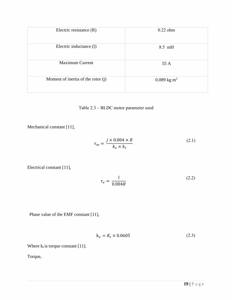
The physical parameters for our example are:
RPM (n) 6100
Power (Pw) 1300 W
19 | P a g e
Electric resistance (R) 0.22 ohm
Electric inductance (l) 8.5 mH
Maximum Current 55 A
Moment of inertia of the rotor (j) 0.089 kg m2
Table 2.3 – BLDC motor parameter used
Mechanical constant [11],
𝜏𝑚 = 𝑗 × 0.004 × 𝑅
𝑘𝑒 × 𝑘𝑡
(2.1)
Electrical constant [11],
τ𝑒 = 𝑙
0.004𝑅
(2.2)
Phase value of the EMF constant [11],
k𝑒 = 𝐾𝑡 × 0.0605 (2.3)
Where kt is torque constant [11].
Torque,

20 | P a g e
Torque = 𝑃𝑤 × 9.554
𝑛
(2.4)
= 1300 × 9.554
6100
= 2.03 𝑁𝑚
Torque constant,
𝐾𝑡 = 𝑇𝑜𝑟𝑞𝑢𝑒
𝐶𝑢𝑟𝑟𝑒𝑛𝑡
= 2.03
55
= 0.04 𝑁𝑚/𝐴
(2.5)
Electrical torque,
𝐾𝑒 = 0.04 × 0.0605 = 0.0024
Mechanical constant,
𝜏𝑚 = 0.089 × 0.004 × 0.22
0.04 × 0.0024= 0.8158
BLDC Motor Transfer Function [11],
G1(𝑠) =
1𝐾𝑒
𝜏𝑚 𝜏𝑒 𝑠2 + 𝜏𝑚 𝑠 + 1
(2.6)
Therefore the transfer function of BLDC motor becomes,

21 | P a g e
G1(𝑠) =416.67
0.38 𝑠2 + 0.82 𝑠 + 1
(2.7)
2.3.2.2 BLDC motor open loop analysis
The open loop step response is shown by using the Simulink tools as shown in figure below.
Figure 2.10 – BLDC motor Simulink diagram
Figure 2.11 – BLDC motor open loop step response

22 | P a g e
2.3.2.3 DC servo motor
The servo motor we used in this project is Futaba S148. The parameters we used in the modeling
are extracted from the datasheet of this motor with corresponding relevant parameters used. Find
below in Table 2.1 the major extracted parameters used for the modeling task.
The physical parameters for our example are:
Modulation: Analog
Torque: 4.8V: 33.3 oz-in (2.40 kg-cm)
6.0V: 41.7 oz-in (3.00 kg-cm)
Speed: 4.8V: 0.28 sec/60°
6.0V: 0.22 sec/60°
Weight: 1.57 oz (44.4 g)
Motor Type: 3-pole
Rotational angle 1800
Table 2.4 – DC Servo motor parameters
2.3.2.4 DC servo motor transfer function
We have used Futaba S-140 DC servo motor for this experiment. The linear mathematical model
(transfer function) for the Futaba S-140 Servo [12] is,
G3(s) =950
𝑠2 + 44𝑠 + 950
(1.8)

23 | P a g e
Figure 2.12 – DC Servo motor Simulink model
Figure 2.13 – Open loop step response of DC servo motor

24 | P a g e
2.4 Proportional controller
The mixture of proportional terms is vital to rise the speed of the response and also to remove the
steady state error [13]. The proportional controller block is reduced to P only as shown in figure
2.14 By using MATLAB we have determined a suitable value for our proportional controller.
Where P = Proportional gain and we set P = 0.5 to get a stable output. In practice, KK2 multirotor
controller board is the PID controller for the system we have developed.
Figure 2.14 – Proportional gain controller
2.5 Control system simulation
From the different outlines required for this trial, a brief steadiness check is required to make the
experimentation at the first case. It would be watched that the main plan close to the ideal is figure
2.3.5.

25 | P a g e
Figure 2.15 – Roll control system Simulink model
Figure 2.16 – Roll control system Simulink model output
26 | P a g e
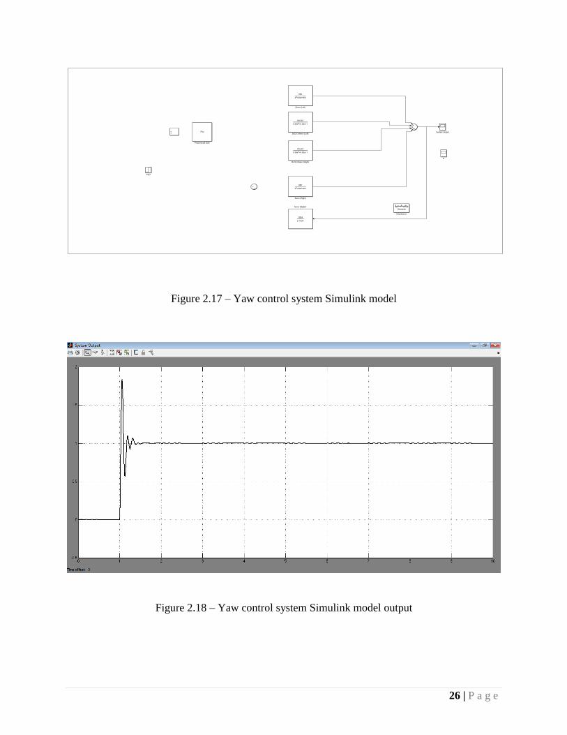
Figure 2.17 – Yaw control system Simulink model
Figure 2.18 – Yaw control system Simulink model output

27 | P a g e
Figure 2.19 – Pitch control system Simulink model
Figure 2.20 – Pitch control system Simulink output

28 | P a g e
2.5.1 Roll control system transfer function
With the assistance of figure 2.15 and equations 2.7 and 2.8, we have computed roll motion control
system’s transfer function. Here the plots incorporate the step response, nyquist diagram, and bode
plot graph.
For this, different m-file were made.
roll.m
Therefore, roll control system transfer function will be:
𝑇𝑟𝑜𝑙𝑙(s) =𝑃 × (𝐺1 + 𝑠𝐺2 + 𝐺3 + 𝐺4) + 𝑃 × (𝐺1 + 𝑠𝐺2 + 𝐺3 + 𝐺4) × 𝐷
1 + 𝑃 × (𝐺1 + 𝑠𝐺2 + 𝐺3 + 𝐺4) ×1024
𝑠 + 1024
(2.9)
The T(s) derived above in the equation 2.9 is the roll control system’s transfer function of the
Drone using all necessarily sufficient parameters available.
clc
s = tf('s');
P = 0.5;
G1 = 416.67/(0.38*s^2+0.82*s+1);
G2 = 416.67/(0.38*s^2+0.82*s+1);
G3 = 950/(s^2+40*s+950);
G4 = 950/(s^2+40*s+950);
D = rand;
systemTransferFunction =
((P*(G1+s*G2+G3+G4))+(P*(G1+s*G2+G3+G4))*D)/(1+(P*(G1+s*G2+G3+
G4))*(1024/(s+1024)));
Drone = zpk(systemTransferFunction); %transfer function
figure;
step(Drone);
figure;
nyquist(Drone), grid;
figure;
bode(Drone), grid;

29 | P a g e
Nyquist Diagram
Real Axis
Imagin
ary
Axis
-1 -0.5 0 0.5 1 1.5-1
-0.8
-0.6
-0.4
-0.2
0
0.2
0.4
0.6
0.8
1
System: Drone
Phase Margin (deg): 124
Delay Margin (sec): 0.0028
At frequency (rad/s): 774
Closed loop stable? Yes
0 dB
-20 dB
-10 dB
-6 dB
-4 dB-2 dB
20 dB
10 dB
6 dB
4 dB
2 dB
0 0.001 0.002 0.003 0.004 0.005 0.006 0.007 0.008 0.009 0.010
0.2
0.4
0.6
0.8
1
1.2
1.4Step Response
Time (seconds)
Am
plit
ude
Figure 2.21 – Roll control system step response
Figure 2.22 – Roll control system Nyquist diagram
30 | P a g e
-25
-20
-15
-10
-5
0
5
Magnitude (
dB
)
Bode Diagram
Frequency (rad/s)
10-1
100
101
102
103
104
-90
-45
0
45
System: Drone
Phase Margin (deg): 124
Delay Margin (sec): 0.0028
At frequency (rad/s): 774
Closed loop stable? Yes
Phase (
deg)
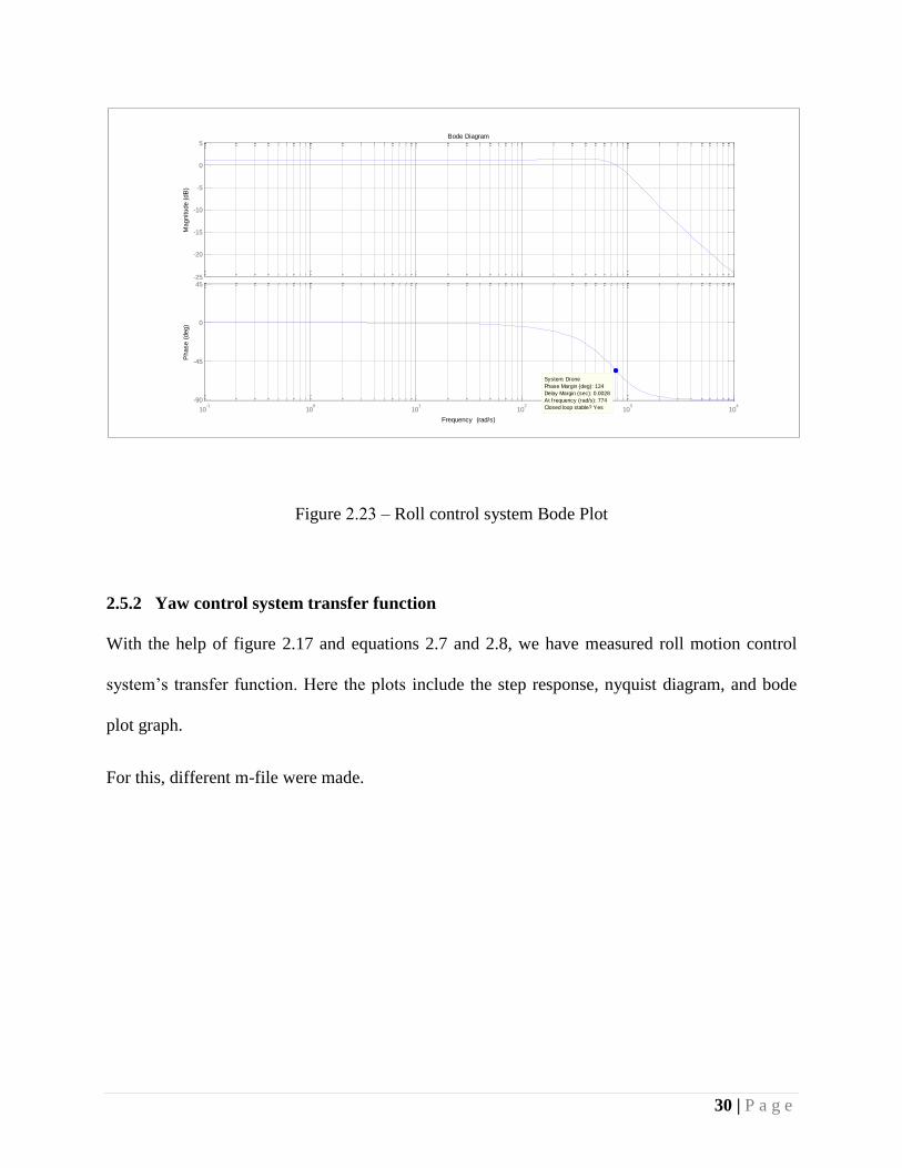
Figure 2.23 – Roll control system Bode Plot
2.5.2 Yaw control system transfer function
With the help of figure 2.17 and equations 2.7 and 2.8, we have measured roll motion control
system’s transfer function. Here the plots include the step response, nyquist diagram, and bode
plot graph.
For this, different m-file were made.

31 | P a g e
yaw.m
Therefore, yaw control system transfer function will be:
𝑇𝑦𝑎𝑤(s) =𝑃 × (𝐺1 + 𝑠𝐺2 + 𝐺3 + 𝑠𝐺4) + 𝑃 × (𝐺1 + 𝑠𝐺2 + 𝐺3 + 𝑠𝐺4) × 𝐷
1 + 𝑃 × (𝐺1 + 𝑠𝐺2 + 𝐺3 + 𝑠𝐺4) ×1024
𝑠 + 1024
(2.10)
The T(s) derived above in the equation 2.10 is the yaw control system’s transfer function of the
Drone using all necessarily sufficient parameters available.
clc
s = tf('s');
P = 0.5;
G1 = 416.67/(0.38*s^2+0.82*s+1);
G2 = 416.67/(0.38*s^2+0.82*s+1);
G3 = 950/(s^2+40*s+950);
G4 = 950/(s^2+40*s+950);
D = rand;
systemTransferFunction =
((P*(G1+s*G2+G3+s*G4))+(P*(G1+s*G2+G3+s*G4))*D)/(1+(P*(G1+s*G2
+G3+s*G4))*(1024/(s+1024)));
Drone = zpk(systemTransferFunction); %transfer function
figure;
step(Drone);
figure;
nyquist(Drone), grid;
figure;
bode(Drone), grid;

32 | P a g e
0 0.002 0.004 0.006 0.008 0.01 0.0120
0.2
0.4
0.6
0.8
1
1.2
1.4
1.6
1.8
2Step Response
Time (seconds)
Am
plit
ude
Nyquist Diagram
Real Axis
Imagin
ary
Axis
-1 -0.5 0 0.5 1 1.5 2-2
-1.5
-1
-0.5
0
0.5
1
1.5
2
System: Drone
Phase Margin (deg): 99.3
Delay Margin (sec): 0.0009
At frequency (rad/s): 1.92e+03
Closed loop stable? Yes
0 dB
-20 dB
-10 dB
-6 dB
-4 dB
-2 dB
20 dB
10 dB
6 dB
4 dB
2 dB
Figure 2.24 – yaw control system step response
Figure 2.25 – Yaw control system Nyquist diagram

33 | P a g e
-20
-15
-10
-5
0
5
10
Magnitude (
dB
)
Bode Diagram
Frequency (rad/s)
10-1
100
101
102
103
104
-90
-45
0
45
System: Drone
Phase Margin (deg): 99.3
Delay Margin (sec): 0.0009
At frequency (rad/s): 1.92e+03
Closed loop stable? Yes
Phase (
deg)
Figure 2.26 – Yaw control system Bode Plot
2.5.3 Pitch control system transfer function
By the aid of figure 2.19 and equations 2.7 and 2.8, we have calculated roll motion control system’s
transfer function. Here the plots combine the step response, nyquist diagram, and bode plot graph.
For this, different m-file were made.

34 | P a g e
pitch.m
Therefore, pitch control system transfer function will be:
𝑇𝑝𝑖𝑡𝑐ℎ(s) =𝑃 × (𝐺1 + 𝐺2 + 𝑠𝐺3 + 𝑠𝐺4) + 𝑃 × (𝐺1 + 𝐺2 + 𝑠𝐺3 + 𝑠𝐺4) × 𝐷
1 + 𝑃 × (𝐺1 + 𝐺2 + 𝑠𝐺3 + 𝑠𝐺4) ×1024
𝑠 + 1024
(2.11)
The T(s) derived above in the equation 2.10 is the pitch control system’s transfer function of the
Drone using all necessarily sufficient parameters available.
clc
s = tf('s');
P = 0.5;
G1 = 416.67/(0.38*s^2+0.82*s+1);
G2 = 416.67/(0.38*s^2+0.82*s+1);
G3 = 950/(s^2+40*s+950);
G4 = 950/(s^2+40*s+950);
D = rand;
systemTransferFunction =
((P*(G1+G2+s*G3+s*G4))+(P*(G1+G2+s*G3+s*G4))*D)/(1+(P*(G1+G2+s
*G3+s*G4))*(1024/(s+1024)));
Drone = zpk(systemTransferFunction); %transfer function
figure;
step(Drone);
figure;
nyquist(Drone), grid;
figure;
bode(Drone), grid;

35 | P a g e
0 0.1 0.2 0.3 0.4 0.5 0.60
0.5
1
1.5
2
2.5
3Step Response
Time (seconds)
Am
plit
ude
Nyquist Diagram
Real Axis
Imagin
ary
Axis
-2 -1.5 -1 -0.5 0 0.5 1 1.5 2 2.5 3-4
-3
-2
-1
0
1
2
3
4
System: Drone
Phase Margin (deg): 23.7
Delay Margin (sec): 0.00565
At frequency (rad/s): 73.2
Closed loop stable? Yes
0 dB
-10 dB
-6 dB
-4 dB
-2 dB
10 dB
6 dB
4 dB
2 dB
Figure 2.27 – Pitch control system step response
Figure 2.28 – Pitch control system Nyquist diagram
36 | P a g e
-100
-80
-60
-40
-20
0
20
Magnitude (
dB
)
Bode Diagram
Frequency (rad/s)
100
101
102
103
104
-180
-135
-90
-45
0
System: Drone
Phase Margin (deg): 23.7
Delay Margin (sec): 0.00565
At frequency (rad/s): 73.2
Closed loop stable? Yes
Phase (
deg)
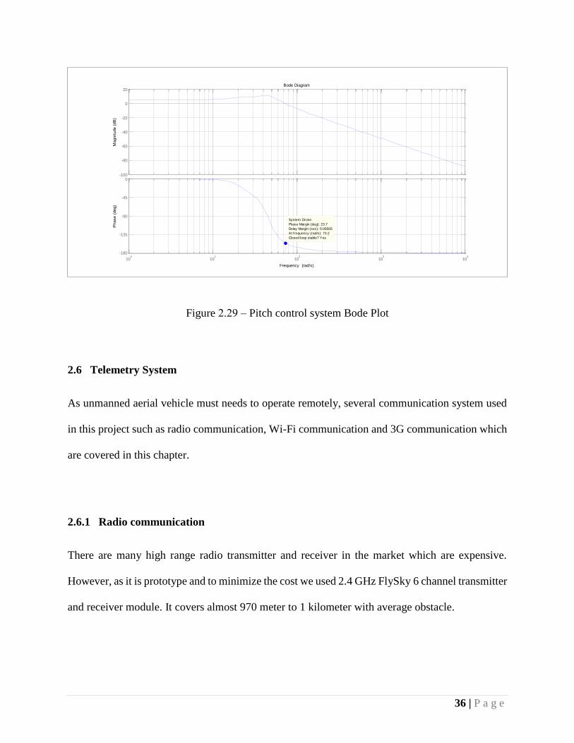
Figure 2.29 – Pitch control system Bode Plot
2.6 Telemetry System
As unmanned aerial vehicle must needs to operate remotely, several communication system used
in this project such as radio communication, Wi-Fi communication and 3G communication which
are covered in this chapter.
2.6.1 Radio communication
There are many high range radio transmitter and receiver in the market which are expensive.
However, as it is prototype and to minimize the cost we used 2.4 GHz FlySky 6 channel transmitter
and receiver module. It covers almost 970 meter to 1 kilometer with average obstacle.

37 | P a g e
Figure 2.30 – FlySky 6 channel radio transmitter and receiver [19]
Over 1200 meter it gets very low signal and completely lost the signal over 1320 meters. To
record precise values we used a car to move around and transmits the signal from a stationary
point.
Technical Specifications:
Radio: 2.4 GHz
Length: 7.4 in (188mm)
Height: 3.8 in (96.5mm)
Width/Diameter: 11.6 in (294.6mm)
Weight: 498.9 g (17.6oz)
By the aid of this device we can control the flight system of our drone. Each channel controls a
specific electronic device which in embedded in our system such as brushless DC motors or servo
motors, thus we can control forward, backward, right or left motion of the prototype.

38 | P a g e
2.6.2 Wi-Fi Communication
Wi-Fi communication used in this experiment for the IP webcam software for short range video
transmission without internet connection. We have used IP webcam android software for video
transmission. It provides live video stream which can be access via local and global computers.
For local communication it uses Wi-Fi communication. Mobile device and the on board computer
needs to connected in the same Wi-Fi network.
2.6.3 Software
An Android mobile device has been installed in our Drone’s payload system for live video stream,
live position tracking and real time voice communication. By the aid of two android software we
have manipulated audio video transmission and GPS position tracking system.
2.6.3.1 Live location tracking
The software for the android device has been developed using an open source web application
which is originally provided by Google and maintained by Massachusetts Institute of Technology
(MIT) known as MIT App Inventor. On December 6, 2013 MIT released App Inventor 2 and this
web application has been used to develop the app for the embedded system. A person with very
basic knowledge of programming can develop any android app through this tool. This is very
simple yet effective method to improve any application for android. No substantial software
installation is needed for this and this can be completed just over web browser with a Google
account.

39 | P a g e
2.6.3.2 Live location tracking software architecture
By using MIT app inventor we have developed an Android application for live path tracking. We
have named it “Path Tracker”. The basic function of this application is, it records GPS coordinates
and the current address of the location and sends it to the MySQL web server via PHP. For
displaying data using Google Map API v3 it draw a red line through the each points it has travelled.
In addition, it records data to when it starts it journey and stops and on the basis of this data it
displays the average speed and distance.
Figure 2.31 – Live location tracking software
Figure 2.19 shows that a sample hovering data and from that we can see the average speed of our
prototype is 24 kilometre per hour.

40 | P a g e
On the other hand, this data can be also accessed by computer from any place as all the data stored
in the server. For the test purpose we have built a website in a free hosting server which can be
accessed from both mobile and computer.
Figure 2.32 – Flow diagram of live location tracking software
2.6.3.3 Live location tracking website architecture
In this experiment, we have built a very simple yet effective website to upload, download and
display necessary data. We have used MySQL database to store data and PHP program to upload,
download, calculate and display data. In addition, we have used HTML and jQuery to make a
interactive display.

41 | P a g e
Figure 2.33 – Flow diagram of live location tracking website
At the beginning, “index.php” file takes mobile number of the user and sends a get request to the
database by “list.php”. If mobile number exists then it displays all the track lists that are recorded
by a user. Then when a user selects an item from the list it will call “map.php” and this file reads
all the relevant data that are stored in the database. After that, as it is already connected with Google
Map Api V3, it gets the map of the relevant GPS coordinates and draws a red line through all
points. In addition, it shows an animated marker at the last point. Finally, “analytics.php” file reads
data from the database and calculates average distance by the aid of Google Map Api and we
divide that distance value by the duration of flight and get the speed per hour.

42 | P a g e
2.6.3.4 Live video stream
Live video streaming can be implemented by using 5.4 GHz 500 mw wireless video transmitter
and receiver but it is too expensive ($USD 630). To reduce the cost in this experiment we have
used an Android mobile phone. In comparison with 5.4 GHz 500 mw wireless video transmitter
and receiver mobile phone is much cheaper (USD $86), consumes less power, supports internet
connections that enable to communicate globally via internet and more intelligent with GPS and
other sensors.
For live video streaming we have used IP-Webcam android application. IP-Webcam turns mobile
phones into a network camera with multiple viewing option. Streaming video inside WiFi network
without internet access is possible. On the other hand, Ivideon cloud streaming supported for
instant global access. In addition, two way audio transmission is also possible in this software.
Figure 2.34 – IP-Webcam live video stream

43 | P a g e
2.7 Hardware implementation
We have used aluminium bar instead of carbon fibre bar to minimise cost. A plastic made landing
gear is used to land the machine softly and spread the landing force over the body. Two brushless
Figure 2.35 – Sketch of the drone
Figure 2.36 – Final product
44 | P a g e
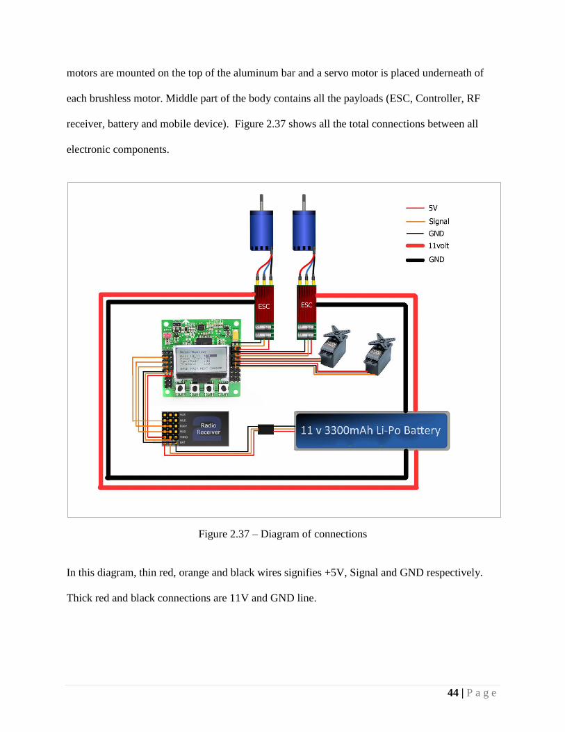
motors are mounted on the top of the aluminum bar and a servo motor is placed underneath of
each brushless motor. Middle part of the body contains all the payloads (ESC, Controller, RF
receiver, battery and mobile device). Figure 2.37 shows all the total connections between all
electronic components.
Figure 2.37 – Diagram of connections
In this diagram, thin red, orange and black wires signifies +5V, Signal and GND respectively.
Thick red and black connections are 11V and GND line.

45 | P a g e
Chapter 3
3.1 Introduction
Measurement is one of the important part of this development project. This chapter contains
precise measurement of the drone we have developed, application of the developed drone and
results.
3.2 Measurements
At the beginning of measurement process we have measured the wait of the drone we have
developed. Its wait is 1.7 kg with all the payloads (ESC, battery, controller and mobile device). As
every brushless motors with a 12 × 4.5 propeller can produce 1.5 kg of thrust, thus with two
propellers we can get almost 3 kg of thrust. Lift equation [14] tells us,
Thrust ≥ Weight (2.11)
So our drone satisfy this equation as we can get 3 kg of thrust and wait of the drone is 1.7 kg.
Table 3.1 contains necessary measurements of the drone we have developed.
Weight 1.7 kg
Motor max tilt angle 35º
Length 0.91 m
Max roll angle 50º

46 | P a g e
Max pitch angle 30º
Max thrust 3 kg
Max extra payload 1 kg
Table 3.1 – Measurements of the drone
3.3 Application of the developed drone
Application of the drone we have developed has covered a vast area of usage. We can use it in
different surveillance purpose. Main applications of this flying machine is given below:
Firefighting
Traffic control & surveillance
Emergency first aid delivery
Product delivery
Military surveillance
3.4 Results
Results we have got from this experimental development is slightly different from the theoretical
results. For example, from the Simulink diagram we can get a very steady output of the brushless
DC motors. However, we have found a lot of unwanted vibration that causes a small oscillation
while flying. This vibration is large at low speed and vibration is low at high speed. On the other

47 | P a g e
hand, for vertical takeoff and landing two servo motors needs to keep in same angle and it was
supposed to be in same angle as we have tuned the controller circuit board in such a way. However,
from the experiment we got a 1º to 3º difference between two servo motors which we need to
control manually every time while flying otherwise it gives a slight yaw motion.
From the table 3.1 we can see that maximum pitch and roll angle is 30º and 50º respectively.
Beyond this range the aircraft lusts its control thought PID controller is compensating, it gives a
large oscillations which causes crash.

48 | P a g e
Chapter 4
4.1 Conclusion
Main aim of this project was to develop a Drone which can be used in several surveillance purposes
and deliver light weight products. For controlling the Drone, 2.4 GHz radio frequency transmitter,
receiver, microcontroller, electronic speed controller, brushless DC motor and servo motor have
been used. MATLAB®/Simulink® has been used to developed the Drone roll, yaw and pitch
control system simulation. The proportional, integral controller action shows the better
performance of controlling the roll, pitch and yaw of developed Drone. For live GPS tracking and
live video footage feedback is also demonstrated. Demonstration shows the successful operation
of Drone tracking and video footage transmission from Drone.
4.2 Limitations
Though we were trying to make it modest, we have some limitations. Firstly, the power issues got
priority. Out prototype can fly up to 25-30 minutes with fully charged battery. However, we can
overcome such issues by using more powerful batteries and motors but that will increase the cost
approximately 52% of the overall cost. Secondly, highest roll angle of the aircraft is 45º. If more
than 45º rotation occurs then it lost control. Thirdly, since our radio controller’s range is
approximately 1 km so we cannot operate this vehicle beyond this range.

49 | P a g e
4.3 Recommendations
This work could be improved by including the precise mechanical instruments made of carbon
fiber. In addition, to have a more precise PID parameters, new methods of PID tuning (the use of
genetic algorithms) could be employed for optimal values. Yaw mechanism for tilting rotors can
be more improved and well controlled by using gear mechanism. On the other hand, to increase
the flight duration 5 cell 5000 mAh Li-Po batteries can be used and it is highly recommended that
a vibration absorber needs to be attached to remove vibration effects and get a stable flight.

50 | P a g e
Appendix
Datasheets of the electronic devices used in this experiment are given below:
ESC:
Constant Current: 60A
Burst Current: 80A
Battery: 2-4S Li-Po
SBEC: 5.5v / 4A
Motor Type: Brushless
Size: 70 x 32 x 17mm
Battery Wire: 14AWG
Motor Wire: 14AWG
Weight: 61g
BLDC Motor:
Model Battery
cell
count
RPM/V Propeller RPM MAX
Current
Thrust
BL 2815/09
3s
920
11 × 7 8360 30A 1350 gm
12 × 6 7000 31A 1550 gm

51 | P a g e
KK2.5.1 multirotor controller board:
Size: 50.5mm x 50.5mm x 12mm
Weight: 21 gram
IC: Atmega644 PA
Gyro/Acceleration: 6050MPU
Auto-level: Yes
Input Voltage: 4.8-6.0V
AVR interface: standard 6 pin.
Firmware Version: 2.1.5
Servo Motor:
Modulation: Analog
Torque: 4.8V: 122.0 oz-in (8.78 kg-cm)
6.0V: 153.0 oz-in (11.02 kg-cm)
Speed: 4.8V: 0.70 sec/60°
6.0V: 0.56 sec/60°
Weight: 2.54 oz (72.0 g)
Dimensions: Length: 1.73 in (43.9 mm)
Width: 0.91 in (23.1 mm)
Height: 1.69 in (42.9 mm)

52 | P a g e
Motor Type: 3-pole
Gear Type: Hybrid
Rotation/Support: Dual Bearings
Li-Po Battery:
Capacity: 3300mAh
Voltage: 11.1V
Max Continuous Discharge: 25C (82.5A)
Max Burst Discharge: 50C (165A)
Weight: 284g
Dimensions: 133*42*23mm
Charge Rate: 1-3C Recommended, 5C Max
2.4 GHz radio transmitter:
Radio: 2.4 GHz
Length: 7.4 in (188mm)
Height: 3.8 in (96.5mm)
Width/Diameter: 11.6 in (294.6mm)
Weight: 498.9 g (17.6oz)

53 | P a g e
References
[1] M. Rouse, "Drone," Whatis.com, December 2013. [Online]. Available:
http://whatis.techtarget.com/definition/drone. [Accessed 3 April 2015].
[2] D. C. L. Kristen Boon, "Warrant Requirement and Suspicionless Drone Searches," in The Domestic
Use of Unmanned Aerial Vehicles, USA, Oxford University Press, 2014, p. 228.
[3] V. Vitto, "Report of the Defense Science Board Task Force on the Investment Strategy for
DARPA," DARPA, Washington, D.C., July 1999.
[4] G. B. Matt Parker, "Quadcopter," Colorado State University, Fort Collins, Colorado 80523, 2012.
[5] R. L. Weiger, "MILITARY UNMANNED AIRCRAFT SYSTEMS IN SUPPORT OF
HOMELAND," U.S. Army War College, Pennsylvania 17013, 30 March 2007.
[6] B. G. Williams, Predators: The CIA's Drone War on AlQaeda, Dulles, Virginia 20166: Potomac
Books, 2013.
[7] J. P. Campbell, Vertical Takeoff & Landing Aircraft, New York: The MacMillan Company, 1962.
[8] "ARES," Lockheed Martin, 2013. [Online]. Available:
http://www.lockheedmartin.com/us/products/ares.html. [Accessed 4th March 2015].
[9] J. Cohen, "Drone Spy Plane Helps Fight California Fires," Science Journal, vol. 318, no. 5851, p.
727, 2007.
[10] M. R. Roberts, "5 drone technologies for firefighting," Fire Chief, 20th March 2014. [Online].
Available: http://www.firechief.com/2014/03/20/5-drone-technologies-firefighting/. [Accessed 4th
April 2015].
[11] O. J. Oludayo, "PID CONTROL OF BRUSHLESS DC MOTOR AND ROBOT TRAJECTORY
PLANNING AND SIMULATION WITH MATLAB®/SIMULINK®," Aalto University, Finland,
2009.
[12] D. Andrisani, "Simulink Models of the Futaba S148 Servo," Purdue University, 6th May 2011.
[Online]. Available:
https://engineering.purdue.edu/~andrisan/Courses/AAE451%20Fall2000/Servo.html. [Accessed 3
1st January 1015].

54 | P a g e
[13] M. M. Noh, "Proportional- Integral (PI) Control," Underwater Robotic Research Group (URRG),
[Online]. Available:
http://urrg.eng.usm.my/index.php?option=com_content&view=article&id=106:proportional-
integral-pi-control-&catid=31:articles&Itemid=70. [Accessed 10 4th April 2015].
[14] J. E. L. Charles E. Dole, Flight Theory and Aerodynamics, USA: John Wiley & Sons, 2000 .
[15] "Drones," Reaching Critical Will, [Online]. Available:
http://www.reachingcriticalwill.org/resources/fact-sheets/critical-issues/6737-drones. [Accessed 4th
March 2015].
[16] S. A. L. Sidley Austin LLP, "Legal issues surrounding the use of commercial drones in Hong Kong
and Singapore," 15th January 2015. [Online]. Available:
http://www.lexology.com/library/detail.aspx?g=d2fb1fa0-2328-45ed-8f19-dd8dc92c96d9.
[Accessed 29th March 2015].
[17] "United States of America: ‘Targeted killing’ policies violate the right to life," Amnesty
International , United Kingdom, 2015.
[18] "BLDC Motor," Emax, [Online]. Available: http://www.emaxmodel.com/. [Accessed 25th April
2015].
[19] Hobbyking, [Online]. Available: http://www.hobbyking.com/hobbyking/store/index.asp. [Accessed
25th April 2015].